weld package semi automatic - sks: welding … · weld package semi automatic ... • industrial...
TRANSCRIPT

Weld Package Semi Automatic
Solutions for mobile operation
The Semi Automatic Weld Package: Weld process controller • DCT power source • Wire feeder • Wire guidance • Control cable • Torch • Consumables
Hand welding with robotic quality
Document-no.: DOC-0122EN | Revision: sks0310.en.6.a.ms
Made for Robots.
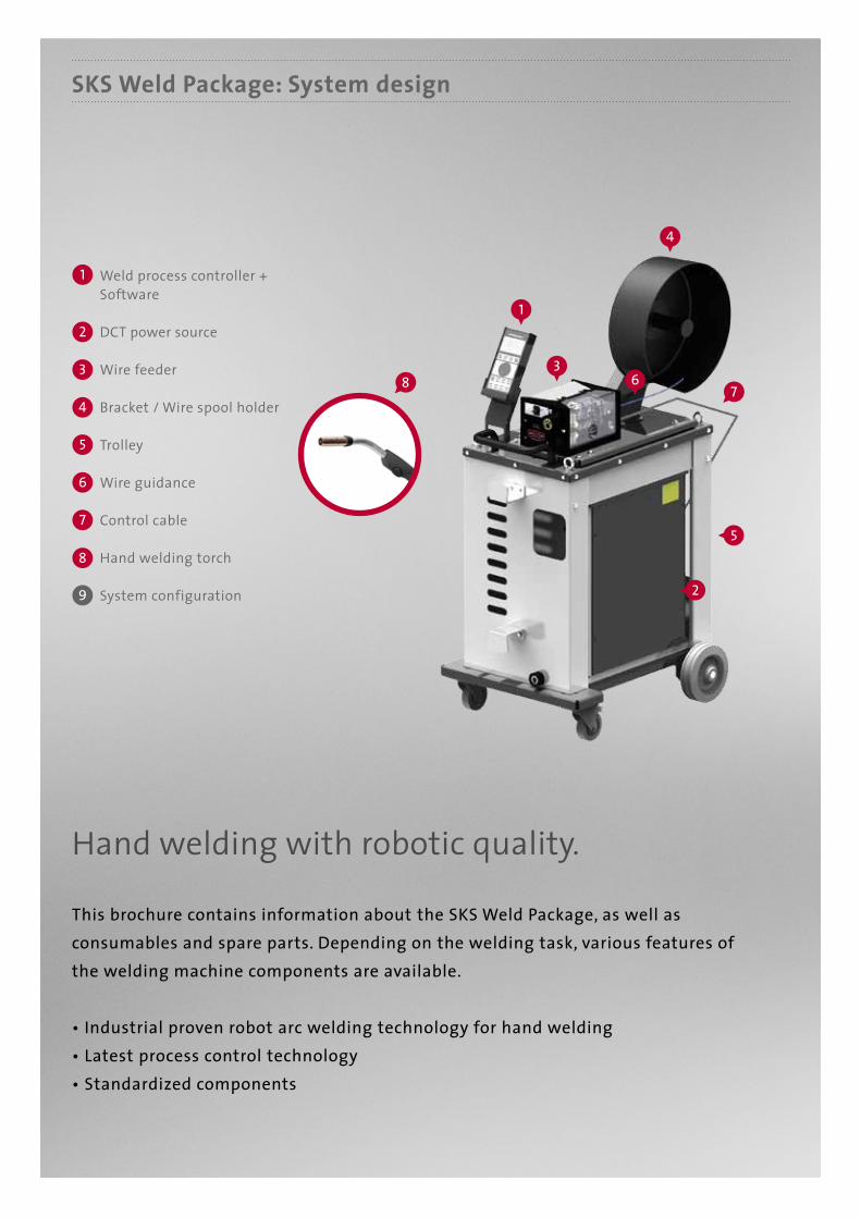
SKS Weld Package: System design
This brochure contains information about the SKS Weld Package, as well as consumables and spare parts. Depending on the welding task, various features of the welding machine components are available.
• Industrial proven robot arc welding technology for hand welding• Latest process control technology• Standardized components
Weld process controller + Software
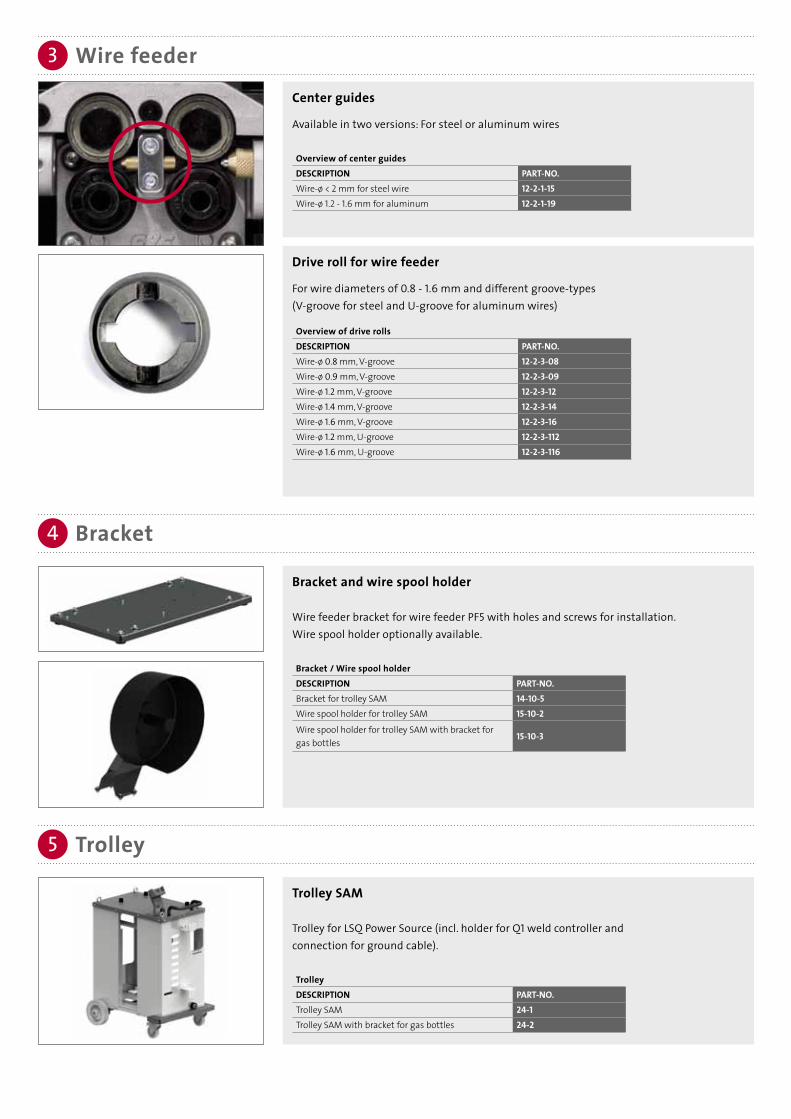
Wire feeder
Bracket / Wire spool holder
Trolley
Wire guidance
System configuration
Control cable
Hand welding torch
DCT power source
Hand welding with robotic quality.
1
5
3
7
2
6
9
4
85
1
3
4
678
2

Processes: MIG/MAG (GMAW), Pulse, MIG Brazing
Wire materials: High-alloy steels, low-alloy steels, aluminum and copper alloys,
nickel-based materials
Wire diameter: 0.8-1.6 mm
Max. power: 420 A - 60 % duty cycle/40 °C, air-cooled
The SKS Semi Automatic Weld Package is designedfor the following welding processes, materials and power range:

1a
1b
Weld process controller
Software
Weld process controller Q1
The Q1 calculates the optimal parameters for each welding process. Only basic data such as material, wire type, wire feed speed and type of gas must be entered.• Processes/features: MIG/MAG (GMAW), I Pulse, U Pulse• Jobs: 14• LCD: Display of measurement values• Ports: USB/SPW Bus with adapter cable
Overview weld process controllerDESCRIPTION PART-NO.Q1 77-7250-00Q1 SPW bus cable 77-7250-20Q1 USB cable 77-7250-10
Q1 Tool software
The additional free software tool allows reading and saving of weld data from/into the Q1 weld controller. With the USB adapter cable the Q1 can be directly connected to the computer. The power is supplied via USB. All parameters are clearly and intuitive displayed intuitive for best usability. Individual jobs as well as the complete content of the Q1 can be saved on the computer and restored into the Q1.
Weld process controller Q1
Q8TOOL
Q1TOOL

Power source2
Power source LSQ3
Power source LSQ5
Power source LSQ5 with Direct Control Technology DCT
The LSQ5 ensures the optimum arc energy. It uniquely adjusts to different weld processes. Unlike conventional power sources with inverter technology, the LSQ5 with Direct Control Technology controls its switching transistors without any fixed clock frequency accordingto the needs of the weld process. Without any delay, the energy needed for the process is provided instantly. The flexible fine tuning is done by a central processor.The CPU continuously analyzes the weld process and current/voltage values on the basis of data obtained and optimally drives the switching transistors of the power section. This results in an extremely high efficiency and a low temperature development.For world-wide usage, voltages can be configured without opening the power source.
LSQ3 power source with Direct Control Technology (DCT) The LSQ3 offers enough power reserves for special weld tasks like chassis and exhaust parts and other thin sheet metal applications. LSQ3: 340 A at 60 % duty cycle/40 °C, 3 x 400 VLSQ3A: 340 A at 60 % duty cycle/40 °C, 3 x 480 V
Overview power sourcesDESCRIPTION PART-NO.LSQ5 77-1185-00LSQ3 77-1184-00LSQ3A 77-1184-10
The main benefits are: • DCT provides a speed regulation up to ten times higher compared to conventional inverter technology. This leads to excellent control behavior and shorter response times.• The weld properties are substantially improved. Software replaces hardware: Fewer components also increase the reliability in continuous operation.
Specifications:DESCRIPTION LSQ5 LSQ3 LSQ3A
Performance 420 A - 60% duty cycle/40 °C
340 A - 60% EDduty cycle/40 °C
340 A - 60% EDduty cycle/40 °C
Processes MIG/MAG (GMAW)Weight 49 kg 37 kg 37 kgPrimary voltage 3 x 400 (480)V 3 x 400V 3 x 480VWall mounting Yes (optional) Yes (integrated) Yes (integrated)Conformities CE, CSA, UL CE CEDimensions 450 x 400 x 540mm 450 x 330 x 540mm 450 x 330 x 540mm
ALTERNATIVE

Wire feeder3
Strong, lightweight and precise.The PF5 wire feeder.
Overview PF5DESCRIPTION PART-NO.PF5 L HE (Euro Connector) 10-2-26PF5 L HP (SKS Power Pin Connector) 10-2-25
Technical dataWeight 3.8 kgMotor 70WWire feeding speed 2.5 - 25 m/minRoll diameter 0.8 - 1.6 mm
Smaller and with less weight accompanied by improved efficiency over conventional wire feeders the PF5 goes along with the steady development of arc welding robots.
Power Feeder PF5
Modern motor, gear and control technology provide a strong performance and highest possible precision. The robust plastic housing is electrically insulated. As a "lightweight" the PF5 is the perfect choice for the new generation of robots with inner cable dress. The industrial proven Power Feeder PF5 is available with an additional monitoring func-tionality: an integrated gas-flow sensor. The weld process controller displays the gas flow values, and can also be triggered to an alarm, in case of a non-defined gas flow rate.
Pressure roll
Pressure roll for wire feeder. Two pressure rolls (Part-No. 12-2-3-0) and two locating bolts (Part-No. 12-2-1-20) are already included in the PF5.
Pressure rollDESCRIPTION PART-NO.Pressure roll for steel, bronze (replacement part) 12-2-3-0
Locating bolt for pressure roll for steel, bronze (replacement part)
12-2-1-20
Pressure roll for aluminum, U-groove 1.2 mm 12-2-5-112Pressure roll for aluminum, U-groove 1.6 mm 12-2-5-116Locating bolt for pressure roll (aluminum) 12-2-1-23Knurled screw for pressure roll (aluminum) 12-2-1-24
Drive roll for wire feeder
For wire diameters of 0.8 - 1.6 mm and different groove-types (V-groove for steel and U-groove for aluminum wires)
Overview of drive rollsDESCRIPTION PART-NO.Wire-ø 0.8 mm, V-groove 12-2-3-08Wire-ø 0.9 mm, V-groove 12-2-3-09Wire-ø 1.2 mm, V-groove 12-2-3-12Wire-ø 1.4 mm, V-groove 12-2-3-14Wire-ø 1.6 mm, V-groove 12-2-3-16Wire-ø 1.2 mm, U-groove 12-2-3-112Wire-ø 1.6 mm, U-groove 12-2-3-116
Bracket and wire spool holder
Wire feeder bracket for wire feeder PF5 with holes and screws for installation.Wire spool holder optionally available.
Bracket / Wire spool holderDESCRIPTION PART-NO.Bracket for trolley SAM 14-10-5Wire spool holder for trolley SAM 15-10-2
Wire spool holder for trolley SAM with bracket for gas bottles
15-10-3
Trolley SAM
Trolley for LSQ Power Source (incl. holder for Q1 weld controller andconnection for ground cable).
TrolleyDESCRIPTION PART-NO.Trolley SAM 24-1Trolley SAM with bracket for gas bottles 24-2
Wire feeder3
Bracket4
Trolley5
Center guides
Available in two versions: For steel or aluminum wires
Overview of center guidesDESCRIPTION PART-NO.Wire-ø < 2 mm for steel wire 12-2-1-15Wire-ø 1.2 - 1.6 mm for aluminum 12-2-1-19

Wire guidance6
ALTERNATIVE
With the new SKS polymer guidance, the high efficiency of the whole system extends up to the drum.
Advantages of polymer wire guidance
• Extraordinary good glide properties reduces motor load• Minimized abrasive wear and reduced dirt in wire feeder and torch system• Lightweight design and a high inherent stability for easy installation• Length can be freely chosen by the customer• Cost optimized exchange: only the polymer conduit must be changed, connectors are reuseable.• Optimized materials for longer life and reduced downtimes
Wire inlet body with quick
coupling at wire feeder
Connector for polymer conduit
Polymer conduit
Drum connector
1
4
2
3
Wire inlet bodies for additional systems
Beside the wire inlet body for the SKS wire guidance, inlet bodiesfor additional systems are available.
Overview of wire inlet bodies for additional systemsDESCRIPTION PART-NO.M10 with internal thread for ESAB 10-2-0-50UNF 3/8" x 24 with external thread 10-2-0-51with 9.6 mm bore hole 10-2-0-52with 13 mm bore hole 10-2-0-53with PG9 thread 10-2-0-56with 1/4” internal thread 10-2-0-60
Aluminum inlets for wire inlet bodiesDESCRIPTION PART-NO.for types 50/52/53/54/59/60/61 10-2-0-57-3for types 51/55/56 10-2-0-58-3
ALTERNATIVE

Wire guidance6
1
3
4
2
Wire inlet body with quick coupling
Wire inlet body for PF5 with quick coupling
Wire inlet body with quick couplingDESCRIPTION PART-NO.Wire inlet body with quick coupling 10-2-0-61
Polymer wire conduit
Polymer wire conduit (sold by meter)
Polymer wire conduitDESCRIPTION PART-NO.Polymer wire conduit, blue 44-9-1
Connection for wire drum
Quick connector with ceramic inlet
Connection for wire drumDESCRIPTION PART-NO.Connection wire drum 44-40-1
Connection nipple for polymer conduit
Connection nipple for polymer conduit
Connection nipple for polymer conduit DESCRIPTION PART-NO. Please note:Connection nipple for polymer conduit 44-40-7 Two connection nipples
necessary.

Ground cable with 70 mm2 connector and cable plug
Cables with larger diameters are available on request.
Overview ground cableLENGTh PART-NO.3 m 2280781035 m 228078105
LENGTh PART-NO.6 m 22807810610 m 228078100
Coaxial power cable
Coaxial power cable 72 mm2 with internal gas flow
Overview of cable bundles lengthsLENGTh PART-NO.1 m 20-4-1-13 m 20-4-1-35 m 20-4-1-5
Cable bundles7a
Ground cable7b
Control cable7c
Clamp for ground cable
400 A with connection bolt M10
Clamp for ground cableDESCRIPTION PART-NO.Clamp for ground cable 91-66-001801
LENGTh PART-NO.7 m 20-4-1-710 m 20-4-1-10
Control cable: L700/SPW-bus
Standard control cable to connect the components:Weld controller, power source, wire feeder.
Overview of control cablesLENGTh PART-NO.0,5 m 5410310501 m 5410310012 m 5410310023 m 541031003
LENGTh PART-NO.5 m 5410310057 m 54103100710 m 541031000

Processes: MIG/MAG (GMAW), Pulse, MIG Brazing
Wire materials: High-alloy steels, low-alloy steels, aluminum and copper alloys,
nickel-based materials
Wire diameter: 0.8-1.6 mm
Max. power: 420 A - 60 % duty cycle/40 °C, air-cooled
The SKS Semi Automatic Weld Package is designedfor the following welding processes, materials and power range:
hand welding torch8
Ergonomic design
Benefits of robotic arc welding now available for hand welding:• Long lasting with high quality parts• High operational times of consumables• Air-cooled even with heavy duty applications• Less repairs• Standard consumables

hand welding torch
hand welding torch: Accessories
8a
8b
hand welding torch (without consumables)
hand welding torch (without consumables)Description PART-NO.up to 300 A (Euro Connector), ZK, 3 m 51-300-245-3Eup to 300 A (Euro Connector), ZK, 4 m 51-300-245-4Eup to 300 A (Euro Connector), 3 m 51-300-45-3Eup to 300 A (Euro Connector), 4 m 51-300-45-4Eup to 300 A (Power Pin Connector), 3 m 51-300-45-3Pup to 300 A (Power Pin Connector), 4 m 51-300-45-4P
Insulator
InsulatorDESCRIPTION PART-NO.Torch neck Insulator 58-1-5
Liner for torch cable
For the following diameters and filler materials:
Steel, bronze (wire-ø 0.8 - 1.0 mm)LENGTh PART-NO.5.0 m 44-20-0810-50
Steel, bronze (wire-ø 1.2 - 1.6 mm)
LENGTh PART-NO.
5.0 m 44-20-1216-50
Aluminum (wire-ø 1.0 - 1.6 mm)LENGTh PART-NO.5.0 m 44-25-1016-50
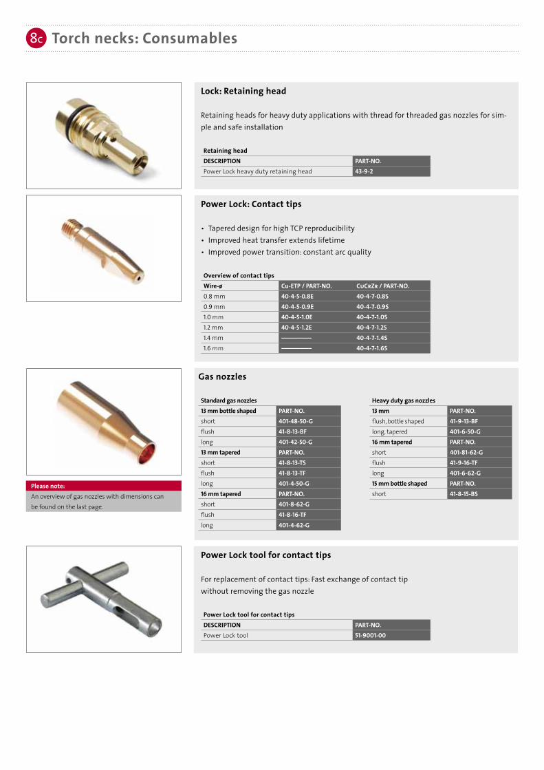
Power Lock: Contact tips
• Tapered design for high TCP reproducibility• Improved heat transfer extends lifetime• Improved power transition: constant arc quality
Overview of contact tipsWire-ø Cu-ETP / PART-NO. CuCrZr / PART-NO.0.8 mm 40-4-5-0.8E 40-4-7-0.8S0.9 mm 40-4-5-0.9E 40-4-7-0.9S1.0 mm 40-4-5-1.0E 40-4-7-1.0S1.2 mm 40-4-5-1.2E 40-4-7-1.2S1.4 mm –––––––––– 40-4-7-1.4S1.6 mm –––––––––– 40-4-7-1.6S
Lock: Retaining head
Retaining heads for heavy duty applications with thread for threaded gas nozzles for sim-ple and safe installation
Retaining headDESCRIPTION PART-NO.Power Lock heavy duty retaining head 43-9-2
Torch necks: Consumables8c
Power Lock tool for contact tips
For replacement of contact tips: Fast exchange of contact tip without removing the gas nozzle
Power Lock tool for contact tipsDESCRIPTION PART-NO.Power Lock tool 51-9001-00
heavy duty gas nozzles13 mm PART-NO.flush, bottle shaped 41-9-13-BFlong, tapered 401-6-50-G16 mm tapered PART-NO.short 401-81-62-Gflush 41-9-16-TFlong 401-6-62-G15 mm bottle shaped PART-NO.short 41-8-15-BS
Gas nozzles
Standard gas nozzles 13 mm bottle shaped PART-NO.short 401-48-50-Gflush 41-8-13-BFlong 401-42-50-G13 mm tapered PART-NO.short 41-8-13-TSflush 41-8-13-TFlong 401-4-50-G16 mm tapered PART-NO.short 401-8-62-Gflush 41-8-16-TFlong 401-4-62-G
Please note: An overview of gas nozzles with dimensions canbe found on the last page.
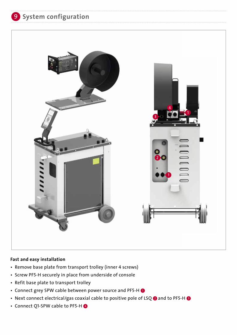
System configuration9
3
2
1
14
Fast and easy installation• Remove base plate from transport trolley (inner 4 screws)• Screw PF5-H securely in place from underside of console• Refit base plate to transport trolley• Connect grey SPW cable between power source and PF5-H 1
• Next connect electrical/gas coaxial cable to positive pole of LSQ 2 and to PF5-H 3
• Connect Q1-SPW cable to PF5-H 4

System configuration9a
Dimensions in mm.
Gas nozzles: Overview dimensions9b
Gas nozzle PART-NO.:
13 mm bottle shaped
16 mm tapered
13 mm tapered
16 mm heavy duty
13 mm heavy duty
401-48-50-G 41-8-13-BF 401-42-50-G 41-8-13-TS 41-8-13-TF 401-4-50-G 41-9-13-BF 401-6-50-G
16 17 17 1817 1816 16
24 24 27 2724 2424 24
13 13 13 1313 1313 133 3 30 0 03 3
70 70 70
Q1 Benefits
1 DisplayMulti-line LCD for a clear display of parameters and values
2 Operating keysOperating keys for the direct selection of functions
3 Rotary knobRotary knob for a comfortable menu and parameter selection
4 Job keysJob keys for the direct selection of different weld programs
5 SPW/USB InterfaceSPW/USB Interface for connecting to the weld system (power source) or to a PC. With an USB adapter cable the Q1 weld parameters and jobs can be saved and restored easily.
Q1 LCD Display (illuminated)
1 Navigation line
2 Cursor
3 Status line
1
1
3
2
2
4
3
5
Gas nozzle PART-NO.:
15 mm bottle shaped
41-8-15-BS 401-8-62-G 41-8-16-TF 401-4-62-G 401-81-62-G 41-9-16-TF 401-6-62-G
24 24 24 27 27 27
16 16 16 16 16 163 30 03 3
70 70

Subject to change.
SKS Welding Systems GmbH | Marie-Curie-Strasse 14 | 67661 Kaiserslautern | GermanyPhone +49(0)6301/7986-0 | Fax +49(0)6301/7986-119