weld 20 introduction to gas metal arc welding gmawchs.chicousd.org/documents/library/welding/welding...
TRANSCRIPT
1
Weld 20
Introduction to Gas Metal Arc Welding GMAW
Fall 2009 1. Introduction a. Syllabus and Grading. b. Weld Sign-Off Sheets. c. Personal Equipment List. d. Clean-up Procedures.
• Turn off machine & gas valve. • Clean metal out of the booths. • Scrap metal goes in the scrap metal bins outside. • Do not quench metal in the sinks. • Put all tools away. • Put all of your personal items away. • Sweep the booths w/ broom & dust pan. • Clean all counter surfaces.
e. The shop (Yuba College) is not liable for your personal equipment. f. 1hr clean-up assignment at the end of the semester. g. Shop Safety. 2. Welding Terms a. Fusing; heating two or more metals or nonmetals until they become liquid, then allowing them to join and ___________. b. Fusion Welding; the use of heat and/or pressure to join two or more pieces of material to form one continual piece indistinguishable from one another. Welding always happens above ______ degrees F. c. Adhesion Welding; Brazing & Soldering, does not melt _____ _____. (Coalescence of metals)
d. Electrode; Filler metals designed to have _________ running though them. e. Rod; Filler metals that are________ to the welding puddle, melts by heat of flame (OAW) or arc (GTAW).
3. Arc Welding a. Welding process which uses an _______ for welding heat. Processes b. SMAW; Shielded Metal Arc Welding
• Stick welding, arc welding and stick arc • Uses a flux covered “__________” electrode • Flux creates shielding gas to protect _______. (Oxygen, Nitrogen) • Constant _________ power source.
c. GMAW; Gas Metal Arc Welding • Also referred to as MIG/MAG, Micro-wire or CO² welding • MIG – Metal ______ Gas; inert or non-reactive gas, Argon,
Helium. • MAG – Metal Active Gas; CO2
2
• Uses continuous wire as an electrode & shielding gas in place of ________.
• Uses Constant ___________ power source. • Past - less than 1% of filler metal sold. • Today - more than ___% of filler metals sold. • Faster travel speeds, smaller wire sizes, less expensive shielding
gases, improved welding techniques and higher deposition rates.
• Welds both ferrous (____ ______) and non-ferrous metals. • Welds a wide range of metal thicknesses. • Less smoke so the weld puddle can be clearly seen by the welder. • Faster welding speeds and __________. • Decrease in equipment development and cost. • Equipment is _______ to use. • Easy _________ to learn.
d. FCAW; Flux _________ Arc Welding
• Uses a _______ ________ continuous wire as it’s electrode. • Can be inner shield or outer shield (needs a shielding gas) • Used where very ________ deposition rates are required. • Usually used for _________materials.
e. GTAW – Gas __________ Arc Welding
• TIG – Tungsten________ Gas • Heliarc – Helium was shielding gas. • Used where ___________ and control of the weld puddle is
required. • Uses a ___ __________ tungsten electrode and rod for filler metal.
4. Flame Welding a. Welding process which uses a __________ for welding heat. Process b. OAW; Oxy-Acetylene Welding
• Mixture of Oxygen & Acetylene to create flame as______ source. • Creates ______ gas which shields molten pool from atmosphere. • Filler rod added to increase weld _________. • Manual process, used primarily for ______ gauge steel and repair
work. 5. Cutting a. Cutting process which uses ______ for metal removal. Processes b. OAC; Oxy-Acetylene Cutting
• Mixture of Oxygen & Acetylene to create flame as heat source. • Burning process; metal brought to _______(burning temperature),
Oxygen under pressure is introduced to accelerate burning process and blow away __________ metal.
• Torch designed for cutting.
3
c. PAC; Plasma _____ Cutting • Constricted arc for heat. • High velocity jet of _________ gas removes molten metal. • High speed cutting of ferrous & ___ _________ metals. • Compressed air works for ______ ________.
d. CAC-A; Carbon Arc Cutting - Air
• Air Carbon Arc Cutting or ____ ______. • Arc created between __________ electrode and base material. • Compressed _____ blows away molten puddle. • Constant _________ power source used for SMAW. • Electrode holder designed for CAC.
6. GMAW a. United States; C.L. Coffin, Bare metal electrodes patented in _____. History b. Oxyacetylene welding also being used. c. Bare Electrode welding produced inferior welds, ____________arc. d. 1908; SMAW, coated electrodes developed, displaced ________ electrodes. e. Electrodes improved through the ______. SMAW popular; eliminated interest in the gas shielding process. f. GTAW (TIG) welding was introduced in the _______ and it was the forerunner of the current gas shielded processes.
• Use of inert gas made _______ quality welds for ferrous and non-ferrous metals.
• High cost for _____. • Thick materials required ___________. • Increase in ____________and Magnesium products. • _______ welding process.
g. GMAW; ________ patent for GMAW (MIG/MAG).
• Uses heat of an electric arc produced between a ________ wire electrode and the base metal.
• Arc is created by passing electricity through an __________ gas • Atoms are ionized when they lose an electron creating a
____________ charge. • The ions flow from + to – and – to +. • Approximately ______% of the heat is carried by the electron
and the rest is carried by the positive ions. • The current GMAW process displaced the slower _________
process. • Immediately became popular and was used to weld ________
(do not contain iron) metals. • MIG was originally used with ________ to weld aluminum. • Could also be used to weld mild and low alloy ________, cost of
the inert gas much higher than flux coated electrodes.
4
• Flux coated electrodes produce ______. Discovery lead to use of CO² in the MIG process on Mild and lo-alloy steels.
• Originally, problems with porosity in welds due to low quality CO² and ___________.
• CO² process became very popular in the ________ with higher quality gases.
• Limited to flat & horizontal welds, spatter problems, very fast- hard to operate manually.
• Improved ________ ________ (Constant Voltage) lead to; reduced spatter, smaller wire (Micro-wire) and puddle size, more controlled arc length, welding in all positions.
• Micro-wire used 100% CO² shielding gas, most commonly used gas today on ________ ________.
• ________ added to soften arc. More expensive. • More __________ than SMAW; higher quality welds, no slag =
less clean-up, little to no spatter, higher deposition rates. • _________; Spray/ Pulse Spray developed, not commercially
viable until solid state electronics were developed. 7. GMAW Types a. Semiautomatic
• Machine controls the wire feed. • Movement of the welding gun controlled by _______. • Machine controls arc ________. • Most popular method.
b. Mechanized • Machine controls the arc length, wire feed and joint guidance of
the gun (not hand held). • Operator controls the ______________.
c. Automatic • Uses equipment that is not constantly controlled by an operator. • Machinery controls the welding parameters, arc length, joint
guidance and wire feed. • __________ most popular method.
d. Manual • Cannot be done with this process
8. GMAW Advantages a. Highly______________ Process
• Semiautomatic process. • Eliminates the starting and stopping when changing __________
or filler metal like GTAW and SMAW. • Higher ____________ rates. • Saves time with no or little clean-up of _________ and spatter. • ________consumable electrode process that can weld most all
commercial metals and alloys, ferrous and non ferrous.
5
• Variables can be set prior to welding and they will remain constant throughout the ________.
• A higher percentage of filler metal is ___________in the weldment.
• One welding package can weld many types of joints __________ changing equipment.
• ____________ operation, no welding breaks as with stick welding. b. Weld Quality
• Eliminates starting and stopping failure, wire is _____________ fed.
• Low ___________ process; alloy steels can be welded with less risk of cold cracking,
• Low heat input with high current density, Smaller _______(Heat Affected Zone), less distortion, more penetration on thin materials.
• No flux on electrode wire to attract ___________. c. Ease of Operation
• Less ________; allows the welding arc to be clearly seen reducing slag inclusions, incomplete fusion, crater cracking, etc.
• Allows the operator to concentrate on the weld _________. • Ability to weld in any __________. • Some lighter weight power sources can be hand-carried.
d. Versatility
• Multiple metal___________ methods. • Short arc (Short Circuit Transfer) used on ________ gauge
materials. • Globular- no longer used on structural applications • Axial Spray; deeper penetration than ______, can produce
smaller fillet welds with relatively the same strength. • Wide current ranges. • CV machines can also run Flux Cored __________, easily be
changed back and forth. e. Increased operator safety
• Low voltages used. 9. GMAW a. Equipment is more complex and costly than _________. Limitations b. Arc requires shielding ______; wind and other elements may blow the shielding gasses away from the arc. c. Larger welding _______.
• Difficult to reach some areas or tight spots. • Visibility of the puddle and weld area affected by the _______.
d. Many parameters to affect welding may be _________ to completely understand.
6
e. Increased ____________costs with equipment: welding guns, liners, drive rollers, etc. f. Less ___________ than SMAW. 10. Equipment a. Examine your equipment before welding (every time).
• Look for _________ cables, worn insulation, or any damages to the equipment.
• Check the __________ lead, a damaged work lead can cause you to become the ground.
• Check welding lead, worn leads can lead to an ______________ arc.
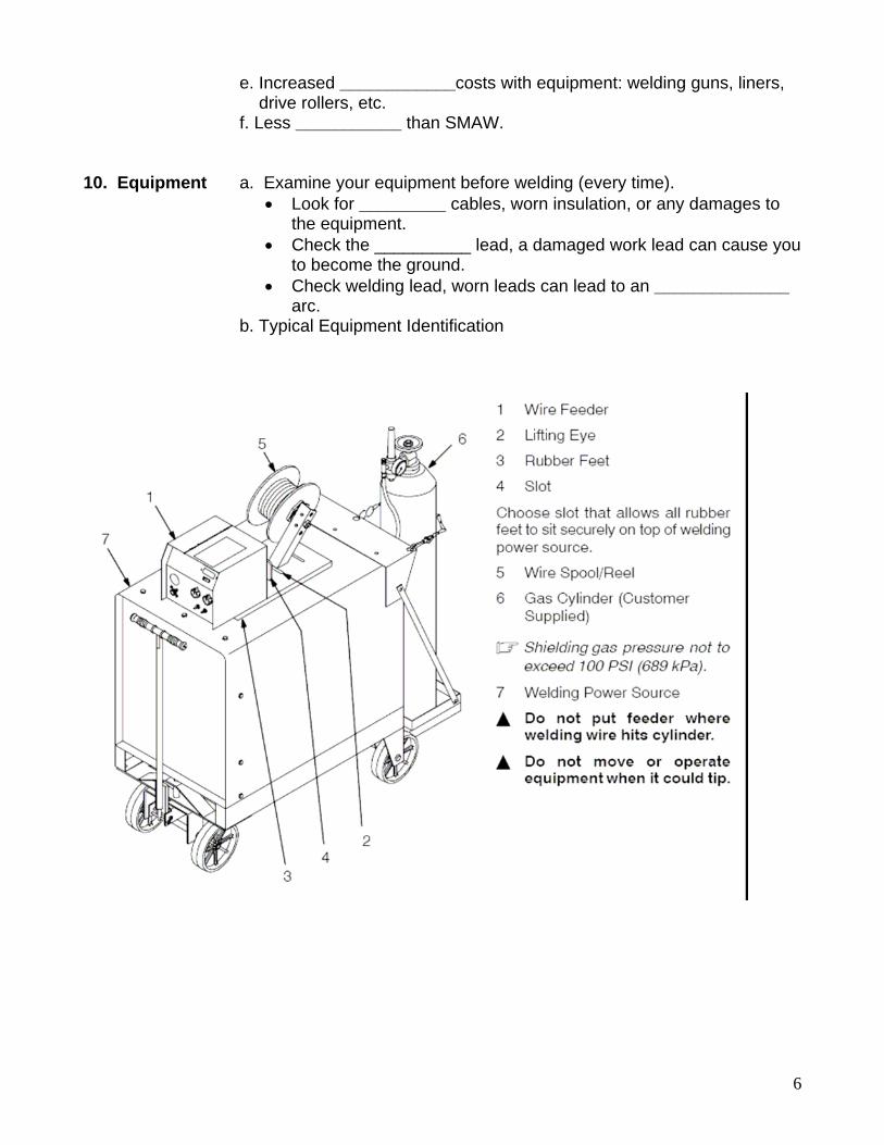
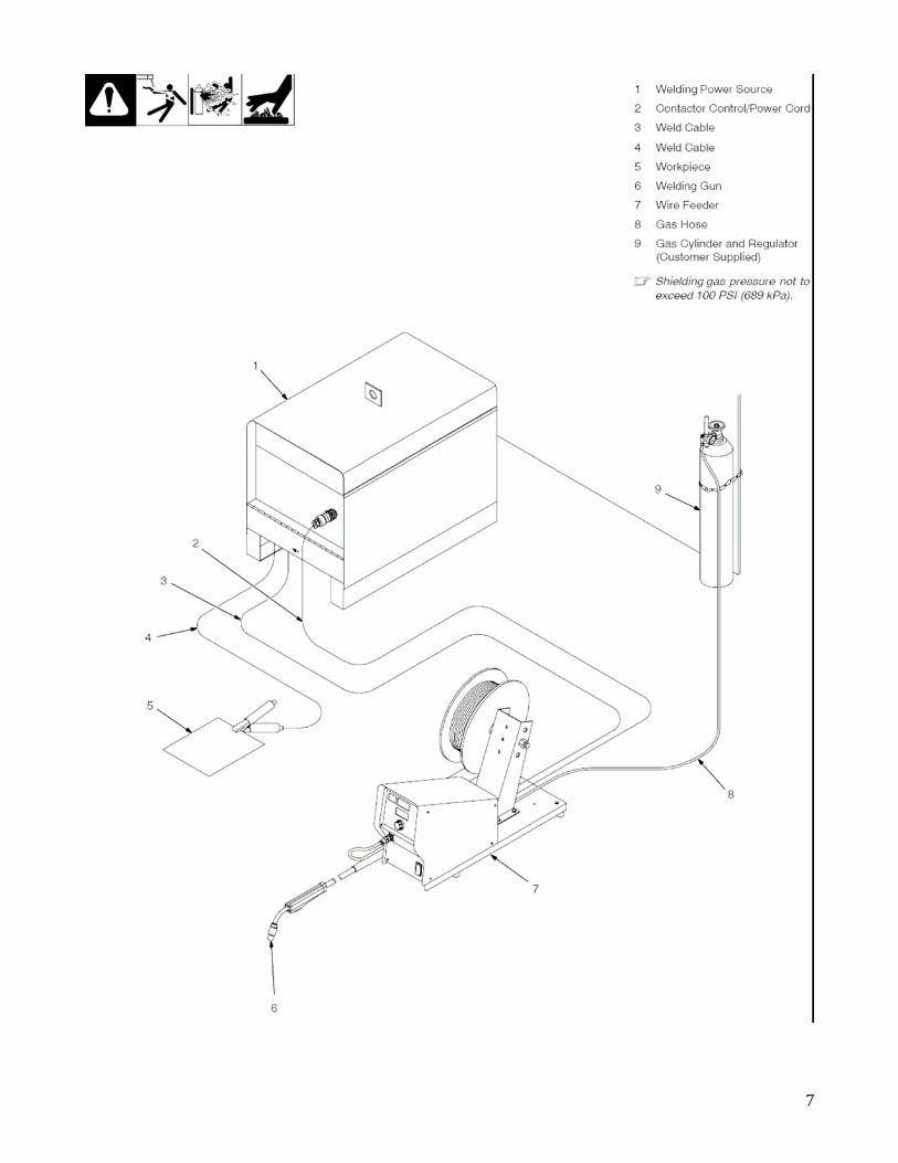
b. Typical Equipment Identification
7
8
11. Basic Welding a. Voltage, Current (amperage) and ______________. Electricity b. Ohms Law; E = IR , I=E/R and R=I/E
• E = Voltage • I = Current • R = Resistance
c. Voltage; _________ that causes electron flow. (pressure in hose)
• Determines potential heat. • Sets Arc Length in CV machine. • Arc length determines how well the puddle or weld pool will
______ (flatten) out. • OCV; Open Circuit Voltage, set on front of machine. Can be as
high as ____V. Voltage while no welding is being done. • Load Voltage; voltage after arc is established. Drop of ____volts
per 100 amps is acceptable. d. Current (Amperage); amount of electron ______past specific point in 1 second. (amount of water coming out of hose)
• Electron flow is __________ to positive (theoretically). • GMAW, amperage is set as _____ ________ speed (WFS) • Wire speed determines amount of weld build-up. • One knob controls both wire speed and ____________. • Effected by ______ _______ distance.
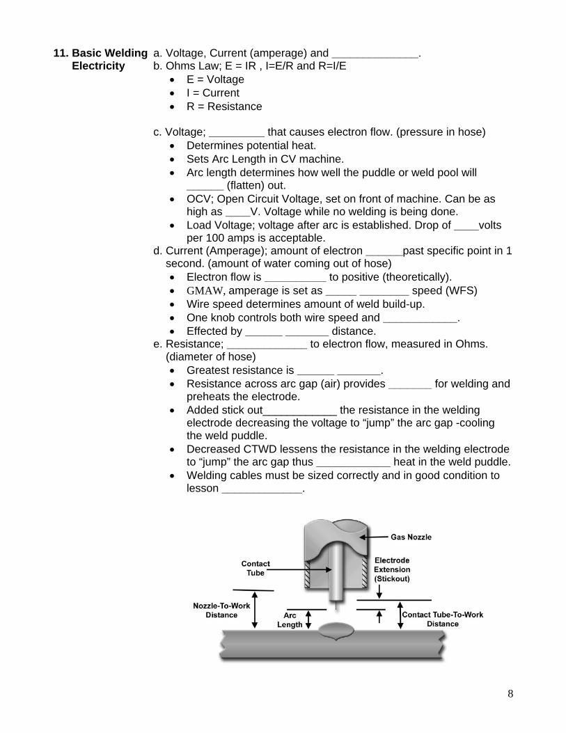
e. Resistance; _____________ to electron flow, measured in Ohms. (diameter of hose)
• Greatest resistance is ______ _______. • Resistance across arc gap (air) provides _______ for welding and
preheats the electrode. • Added stick out____________ the resistance in the welding
electrode decreasing the voltage to “jump” the arc gap -cooling the weld puddle.
• Decreased CTWD lessens the resistance in the welding electrode to “jump” the arc gap thus ____________ heat in the weld puddle.
• Welding cables must be sized correctly and in good condition to lesson _____________.
9
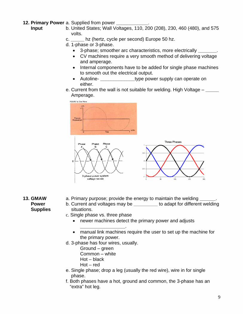
12. Primary Power a. Supplied from power ____________. Input b. United States; Wall Voltages, 110, 200 (208), 230, 460 (480), and 575 volts. c. _____ hz (hertz, cycle per second) Europe 50 hz. d. 1-phase or 3-phase.
• 3-phase; smoother arc characteristics, more electrically _______. • CV machines require a very smooth method of delivering voltage
and amperage. • Internal components have to be added for single phase machines
to smooth out the electrical output. • Autoline- _____________type power supply can operate on
either. e. Current from the wall is not suitable for welding. High Voltage – _____ Amperage.
13. GMAW a. Primary purpose; provide the energy to maintain the welding ______. Power b. Current and voltages may be _________ to adapt for different welding Supplies situations. c. Single phase vs. three phase
• newer machines detect the primary power and adjusts _________________.
• manual link machines require the user to set up the machine for the primary power.
d. 3-phase has four wires, usually. Ground – green Common – white Hot – black Hot – red e. Single phase; drop a leg (usually the red wire), wire in for single phase. f. Both phases have a hot, ground and common, the 3-phase has an “extra” hot leg.
10
14. Power Supply Types a. Generator; ____________ driven generator to produce welding electricity.
• Engine driven generators are popular for welding in the field where ______ electricity is available.
• Generally CC power supplies require another machine to perform GMAW.
• Can produce auxiliary power for __________machine. • A “________” style voltage sensing wire feeder can also be used. • Noisy, require more maintenance, more expensive and require
fuel or an electric motor to run. b. Transformer Rectifier; uses static (nonmoving parts) to _________ the primary power into usable electricity for welding.
• Most popular machines in industry. • Being replaced by ____________. • Transformer converts High Voltage/______ Amperage primary
power to Low Voltage/ _______ Amperage current. • _____________ changes AC to DC current. • Solid State (semiconductors) controls provide the ________ volt
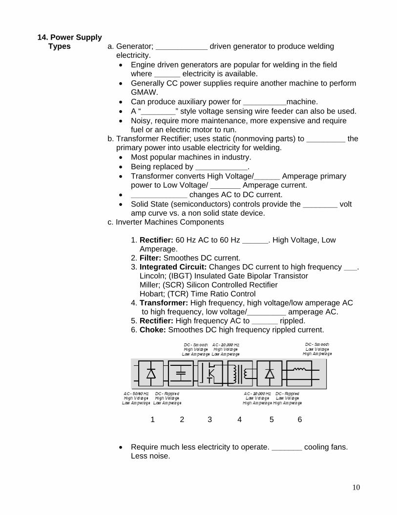
amp curve vs. a non solid state device. c. Inverter Machines Components 1. Rectifier: 60 Hz AC to 60 Hz ______. High Voltage, Low Amperage. 2. Filter: Smoothes DC current. 3. Integrated Circuit: Changes DC current to high frequency ___. Lincoln; (IBGT) Insulated Gate Bipolar Transistor Miller; (SCR) Silicon Controlled Rectifier Hobart; (TCR) Time Ratio Control 4. Transformer: High frequency, high voltage/low amperage AC to high frequency, low voltage/_________ amperage AC. 5. Rectifier: High frequency AC to ______ rippled. 6. Choke: Smoothes DC high frequency rippled current. 1 2 3 4 5 6
• Require much less electricity to operate. _______ cooling fans. Less noise.
11
• _________ response time. Controlled Volt/Amp curve. Utilizes “switches” to turn on or off the flow of electricity.
• Higher switching and control frequency produces stable arc characteristic, more efficiency and greater performance
• Multipurpose models; can accommodate ___ or ___ welding operations.
• Inverters are becoming more inexpensive, more available to welding shops.
• More portable; smaller size/weight. • Smaller _________ windings – more expensive. • More sensitive to cable length.
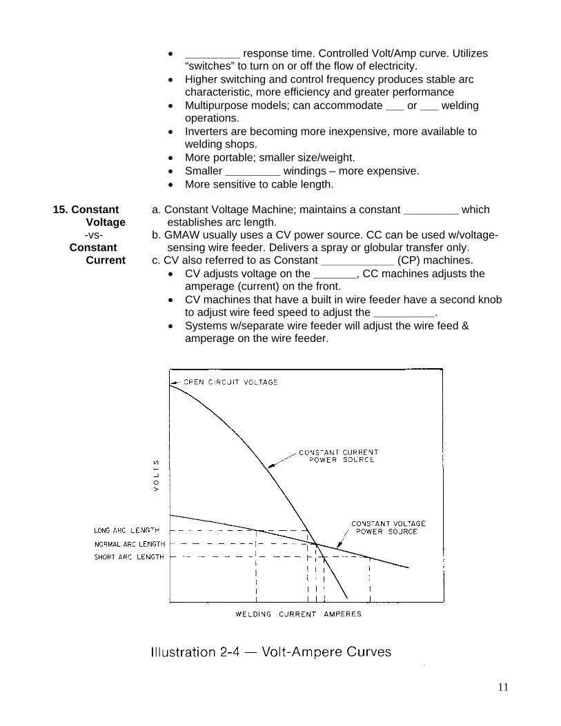
15. Constant a. Constant Voltage Machine; maintains a constant _________ which Voltage establishes arc length. -vs- b. GMAW usually uses a CV power source. CC can be used w/voltage- Constant sensing wire feeder. Delivers a spray or globular transfer only. Current c. CV also referred to as Constant ____________ (CP) machines.
• CV adjusts voltage on the _______, CC machines adjusts the amperage (current) on the front.
• CV machines that have a built in wire feeder have a second knob to adjust wire feed speed to adjust the __________.
• Systems w/separate wire feeder will adjust the wire feed & amperage on the wire feeder.
12
16. Current a. Two types; Alternating current (AC) & ________ Current (DC) Polarity b. DC; two kinds,
• Direct Current Electrode ___________(DCEP) • Direct Current Electrode ___________ (DCEN)
c. AC; heat distribution is relatively ________. • Electron flow - 50% Positive / 50% Negative.
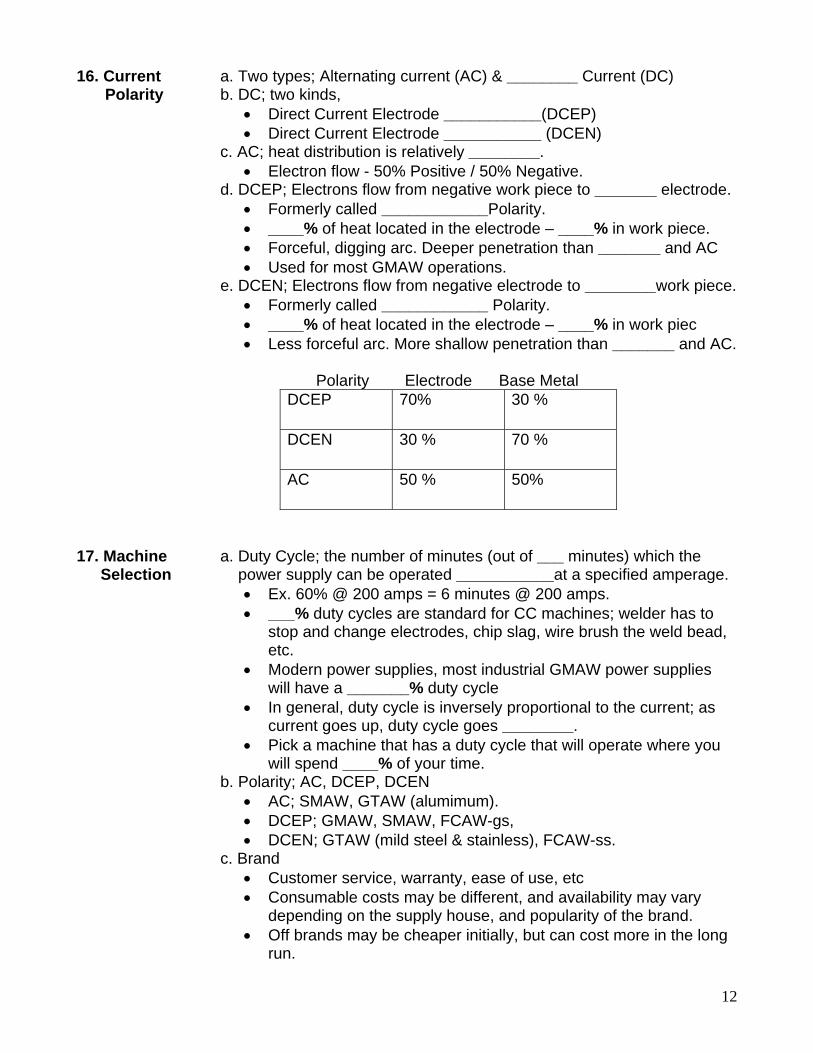
d. DCEP; Electrons flow from negative work piece to _______ electrode. • Formerly called ____________Polarity. • ____% of heat located in the electrode – ____% in work piece. • Forceful, digging arc. Deeper penetration than _______ and AC • Used for most GMAW operations.
e. DCEN; Electrons flow from negative electrode to ________work piece. • Formerly called ____________ Polarity. • ____% of heat located in the electrode – ____% in work piec • Less forceful arc. More shallow penetration than _______ and AC.
Polarity Electrode Base Metal
DCEP 70% 30 %
DCEN 30 % 70 %
AC 50 % 50%
17. Machine a. Duty Cycle; the number of minutes (out of ___ minutes) which the Selection power supply can be operated ___________at a specified amperage.
• Ex. 60% @ 200 amps = 6 minutes @ 200 amps. • ___% duty cycles are standard for CC machines; welder has to
stop and change electrodes, chip slag, wire brush the weld bead, etc.
• Modern power supplies, most industrial GMAW power supplies will have a _______% duty cycle
• In general, duty cycle is inversely proportional to the current; as current goes up, duty cycle goes ________.
• Pick a machine that has a duty cycle that will operate where you will spend ____% of your time.
b. Polarity; AC, DCEP, DCEN • AC; SMAW, GTAW (alumimum). • DCEP; GMAW, SMAW, FCAW-gs, • DCEN; GTAW (mild steel & stainless), FCAW-ss.
c. Brand • Customer service, warranty, ease of use, etc • Consumable costs may be different, and availability may vary
depending on the supply house, and popularity of the brand. • Off brands may be cheaper initially, but can cost more in the long
run.
13
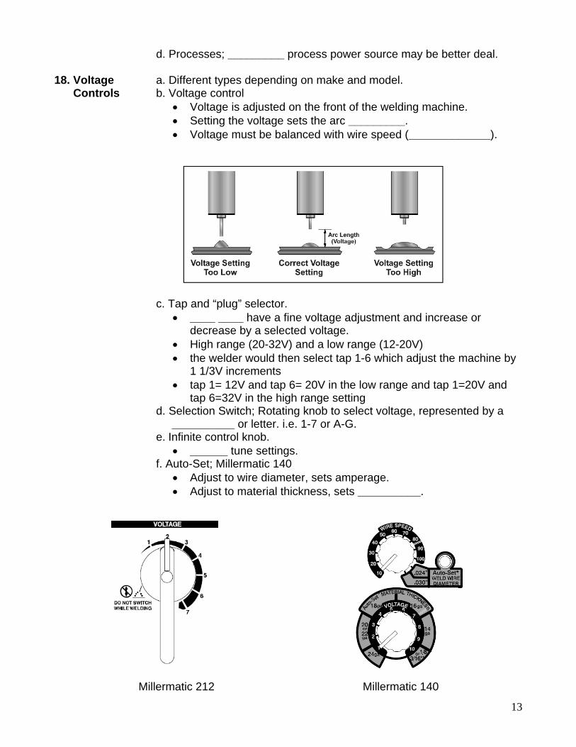
d. Processes; _________ process power source may be better deal. 18. Voltage a. Different types depending on make and model. Controls b. Voltage control
• Voltage is adjusted on the front of the welding machine. • Setting the voltage sets the arc _________. • Voltage must be balanced with wire speed (_____________).
c. Tap and “plug” selector.
• ____ ____ have a fine voltage adjustment and increase or decrease by a selected voltage.
• High range (20-32V) and a low range (12-20V) • the welder would then select tap 1-6 which adjust the machine by
1 1/3V increments • tap 1= 12V and tap 6= 20V in the low range and tap 1=20V and
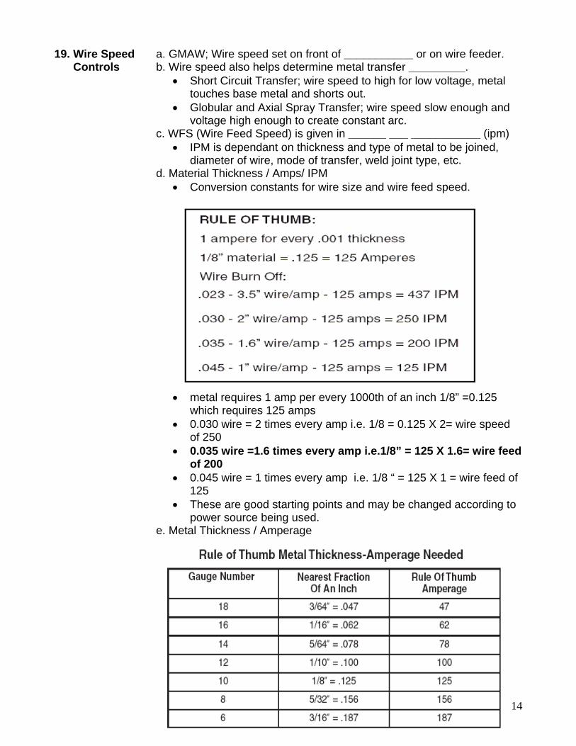
tap 6=32V in the high range setting d. Selection Switch; Rotating knob to select voltage, represented by a __________ or letter. i.e. 1-7 or A-G. e. Infinite control knob.
• ______ tune settings. f. Auto-Set; Millermatic 140
• Adjust to wire diameter, sets amperage. • Adjust to material thickness, sets __________.
Millermatic 212 Millermatic 140
14
19. Wire Speed a. GMAW; Wire speed set on front of ___________ or on wire feeder. Controls b. Wire speed also helps determine metal transfer _________.
• Short Circuit Transfer; wire speed to high for low voltage, metal touches base metal and shorts out.
• Globular and Axial Spray Transfer; wire speed slow enough and voltage high enough to create constant arc.
c. WFS (Wire Feed Speed) is given in ______ ___ ___________ (ipm) • IPM is dependant on thickness and type of metal to be joined,
diameter of wire, mode of transfer, weld joint type, etc. d. Material Thickness / Amps/ IPM
• Conversion constants for wire size and wire feed speed.
• metal requires 1 amp per every 1000th of an inch 1/8” =0.125 which requires 125 amps
• 0.030 wire = 2 times every amp i.e. 1/8 = 0.125 X 2= wire speed of 250
• 0.035 wire =1.6 times every amp i.e.1/8” = 125 X 1.6= wire feed of 200
• 0.045 wire = 1 times every amp i.e. 1/8 “ = 125 X 1 = wire feed of 125
• These are good starting points and may be changed according to power source being used.
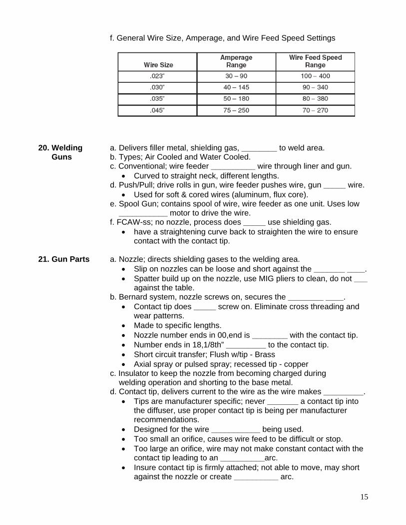
e. Metal Thickness / Amperage
15
f. General Wire Size, Amperage, and Wire Feed Speed Settings 20. Welding a. Delivers filler metal, shielding gas, ________ to weld area. Guns b. Types; Air Cooled and Water Cooled. c. Conventional; wire feeder __________ wire through liner and gun.
• Curved to straight neck, different lengths. d. Push/Pull; drive rolls in gun, wire feeder pushes wire, gun _____ wire.
• Used for soft & cored wires (aluminum, flux core). e. Spool Gun; contains spool of wire, wire feeder as one unit. Uses low ___________ motor to drive the wire. f. FCAW-ss; no nozzle, process does _____ use shielding gas.
• have a straightening curve back to straighten the wire to ensure contact with the contact tip.
21. Gun Parts a. Nozzle; directs shielding gases to the welding area.
• Slip on nozzles can be loose and short against the _______ ____. • Spatter build up on the nozzle, use MIG pliers to clean, do not ___
against the table. b. Bernard system, nozzle screws on, secures the ________ ____.
• Contact tip does _____ screw on. Eliminate cross threading and wear patterns.
• Made to specific lengths. • Nozzle number ends in 00,end is ________ with the contact tip. • Number ends in 18,1/8th” _________ to the contact tip. • Short circuit transfer; Flush w/tip - Brass • Axial spray or pulsed spray; recessed tip - copper
c. Insulator to keep the nozzle from becoming charged during welding operation and shorting to the base metal. d. Contact tip, delivers current to the wire as the wire makes _________.
• Tips are manufacturer specific; never _______ a contact tip into the diffuser, use proper contact tip is being per manufacturer recommendations.
• Designed for the wire ___________ being used. • Too small an orifice, causes wire feed to be difficult or stop. • Too large an orifice, wire may not make constant contact with the
contact tip leading to an __________arc. • Insure contact tip is firmly attached; not able to move, may short
against the nozzle or create __________ arc.
16
• Most contact tips screws into the diffuser; made in different lengths.
• Flush for short circuit transfer- can stick out a maximum 1/8th” past the nozzle with adequate gas flow. Recessed for axial spray or pulsed spray.
• Replace if hole is worn or egg shaped; worn contact tip causes erratic arc, outages, cold lap, improper heating of the filler wire and improper weld characteristics.
• Generally, replace every ______ lbs of wire. e. Diffuser; carries the current to the contact tip, can _________ the shielding gas to provide better coverage. f. Trigger; turns on/off welding circuit, current flow, gas flow, wire feed. 22. Welding Cable a. Supplies welding wire, shielding gas, current to gun.
• Never use to drag machine around. b. Liner; carries the wire to the gun.
• Keep straight as possible, do not kink, ________. • Clean with __________ air every time you change the spool of
wire. c. Braided cable delivers the ___________. d. Gas line to deliver the ___________ gas. 23. Work a. Completes and is part of the welding __________. Connection b. Attaches power source to ________.
• Incorrectly but commonly called the ground connection. Ground connection grounds the ______________(power supply) and equipment.
c. Directs electricity away from the person welding for safety. d. Work Clamp; clamp to work, table, structure.
• Do not __________ through bearings, moving parts. • Insure tight connection; will cause ___________ arc/wire feed.
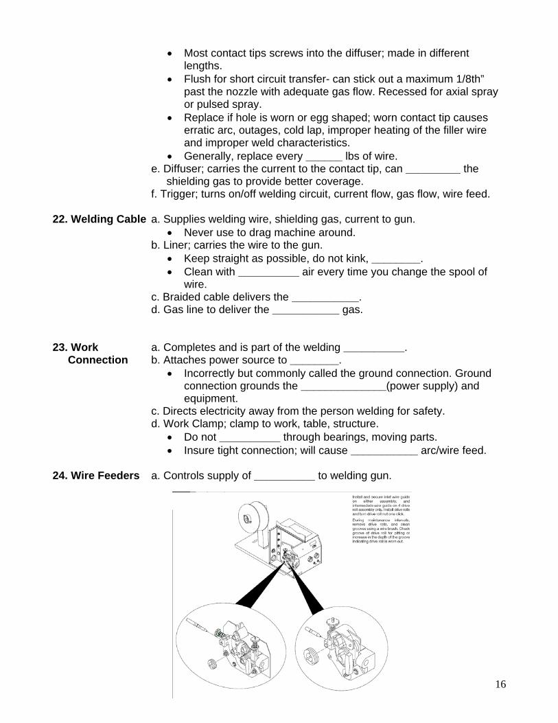
24. Wire Feeders a. Controls supply of __________ to welding gun.
17
b. Constant speed; used only with a Constant ____________ (CV) power source.
• Feeder has control cable connected to ________ __________. • Control cable supplies power to the feeder, capable of _______
control with certain power source/feeder combinations. • Wire Feed Speed (WFS) set on the feeder; will always be
_____________ for a given preset value. c. Voltage Sensing; can be used with either Constant Voltage (CV) or Constant Current (CC) direct current (DC) power source.
• Feeder is powered off of the arc voltage and does not have a _________ _______.
• When set to (CV), feeder is similar to a constant _________ feeder.
• When set to (CC), the wire feed speed depends on the ________ present.
• Feeder changes wire feed speed as the ____________ changes. • Voltage sensing feeder does not have the capability of _________
voltage control. 25. Wire Feeder a. Mode Switch (optional); selects type of mode (spot, intermittent, Controls seam). b. Trigger Lock (in switch); allows welder to feed wire continuously _______ keeping trigger depressed. c. Burn Back Control; prevents wire from sticking in the weld puddle when the trigger is released. _______________ Control. d. Spot Weld Time (optional); controls _______ and ________ of the spot weld process e. Stitch Weld Time (optional); sets duration of the stitch weld when making a long seam weld or a specific weld _________. f. Pre-Flow; controls the time gas flows __________ weld begins - purging weld area. g. Purge; allows welder to clear lines with shielding gas or set flow meter/gauge prior to welding without feeding ________. h. Jog or Inching; moves wire through the line without energizing the wire or ___________ _________. i. Reel Brake Control; stops reel from rotating when welding stops.
• Generally adjusted with a nut in middle of the________. • Should be adjusted so reel stops within ____________ when
welding stops. • Wire should never touch metal housing or positive power lug
__________ 26. Drive Rolls a. Two wheel & Four wheel systems available.
• Make sure roll size matches wire ___________. • Some rollers have two different sizes on one roller. Stamped size
on side of roller will be read on ___________ – opposite groove.
18
• Some feeder systems will have one drive roller and one _________or idler roller.
• Some feeders will have both rollers w/geared teeth. Both rollers _________ wire.
b. Push Type Feeders • Two rolls; solid and _______ wires. • Four rolls; soft or ___________ wires. (FCAW)
c. Push/Pull Type Feeders • Roller sets in both feeder & ______. • _____________ wires or long leads.
d. Roller Shapes • “V” - Groove; solid, ______ ________. • “V” - Knurled; tubular, ______ _______. • “U” - Grooved; soft wires, ______________.
e. Drive Roller Tension • Set only enough pressure to feed wire ______________. • Over tightening flattens the wire. Causes feed issues, may not
make full contact at the contact tip. _________ arc/feed. • Stop wire with your hand by bending the wire over while feeding.
27. Feed a. Equipment settings, work clamp, variable settings. Problems b. Bird Nest; tangled wire inside of the _______ ___________.
• Improper roller pressure – ______ _________. • Wrong inlet/outlet tube, liner diameter per wire ____________. • Wire/tip fusion or burn back. Do not burn off stick-out on edge of
_________. (Safety issue also) • Kinking gun ________. • Negative lead cable lug may cause short inside drive assembly
compartment. Keep lug covered w/____________. c. Slipping:
• Drive Roll tension set _____ _______. • Reel Brake tension set _____ _______. • Drive roll / wire size __________.
c. Worn liner. • Last step, check all other variables and equipment first.
d. Tip Contact; • worn, damaged, _________. • Wire too tight from heat expansion (Spray Arc). May put in
______________ tip. Ex. 0.035” = 0.039” dia. • Crushed wire from excessive _______ pressure, poor tip contact.
28. Shielding a. Critical to quality of the finished weld. Gasses b. Gasses act differently under heat of the arc.
• Effects current flow across the _______. • Effects transfer of molten __________. • Some gasses won’t support some ___________ modes.
19
29. Shielding a. ______________ potential of the gas components. Gas b. Thermal conductivity (affects current density) of the ___________ Criteria ________ components. c. Ability of gas to transfer __________ _________.
• Most important consideration in selecting a shielding gas. • High thermal conductivity levels result in more ____________ of
thermal energy to the workpiece. • Affects the shape of arc and temperature distribution within the
weld region. d. Chemical reactivity of the shielding gas with the __________ weld puddle.
• Inert; Argon, Helium, ___________. • Reactive; CO2, Oxygen, ____________.
e. Selection includes the following (not limited to). • Alloy of wire electrode. • Desired mechanical properties of the deposited weld metal. • Material thickness and Joint Design. • Material Condition; _________, corrosion, resistant coatings or oil. • The mode of metal transfer; Short Arc, Spray, Pulse Spray. • Welding position, Fit-up conditions. • Desired ___________ profile. • Desired final weld bead profile. • _______.
30. Gas Densities a. Shielding gasses have different densities. & Flow Rates b. Lighter or __________ than air.
• Higher flow rates are required for Helium than _____ and Argon. • Often up to ___.
c. Joint configuration, position, stick-out, affect flow rate. • Tee joints require ______gas flow than groove joints. • Welding overhead; slightly ______ gas flow with heavier shielding
gasses. • Longer stick-outs; higher shielding gas flow due to the _________
distance between tip to weld puddle. (Spray Transfer) • Excessive gun ________ can cause poor gas coverage.
d. Gas flow rate; just high enough to __________ shielding for the weld puddle.
• 15 – ___ Cubic Feet Per Hour (CFH); Short Circuit. • 30 – ___ CFH; Axial and/or Pulse Spray.
e. Excessive flow. • Cool puddle too rapidly causing __________. • Turbulence, draw in ___________ contamination to weld puddle. • _______. • Flow meter – _____ ____.
f. Gas drift; ______ maximum air flow for GMAW welding.
20
31. Argon a. Inert Gas; does not react _____________ with molten puddle. b. Chemical symbol; ___. c. ________ commonly used inert gas. d. More dense than ____ (can use lower flow rates). e. 100% Argon can weld nickel, copper, aluminum, titanium and _______________ alloyed metal.
• 100% for _____________ metals most common. • Usually ________for ferrous metals.
f. Largest part in _______ (two part) and ___________(three part) gas mixtures for GMAW. g. Easily ionized; can carry ____________ across long arcs.
• Makes it less sensitive to changes in arc ___________. • Ionization energy is ________eV., • Argon easier to ionize than __________, better arc starting than
helium. h. Lower thermal conductivity rate than other inert gases.
• ________ of helium and hydrogen. i. Gas mixtures with high percentages of __________.
• Penetration profile; finger like projection into the base metal, due to the _________ thermal conductivity.
j. ____________ molten droplet transfer rate. k. Supports axial ________ transfer. l. Provides ___________ action associated with DCEP.
• Important in welding ______________. m. Irregular arc and deposit of metals when welding ___________ metal.
• ______ _________ emit electrons that attract the arc, but are not evenly distributed.
• Problem solved by adding a small amount of __________. • Generally ______is sufficient. • About _______ is acceptable for stainless steel. Prevents scale of
chromium oxide. • Carbon dioxide may be substituted for Oxygen, but more than
_____ is needed. • _____ optimal for ferrous metal. • Carbon Dioxide mix ____________ for ferrous metal; better bead
profile, more stable arc. n. Obtained two ways:
• Cryogenic; ________ _____, separate the gases as the liquid warms, fractional distillation
• Non-cryogenic; separate air with a molecular ______, a screen with very small holes.
32. Helium a. Product of the natural gas industry. b. Atomic symbol; ____. c. Inert Gas; does not _______ chemically with molten puddle. c. __________ than air; flow rates about ________ that of argon.
• Stiffness of gas stream must push atmosphere away from the weld puddle.
21
d. Requires _________ voltage to ionize. • Produces a much_________ arc.
e. Makes welding thicker magnesium and _____________ easier. f. Commonly added to gas mix for ____________ and aluminum. g. Up to ______ helium can be added to argon.
• ____________ power of arc without affecting the desirable attributes of axial spray.
• ____________ helium; transfer process becomes progressively more globular.
h. Broad but _______penetrating bead profile. i. Helium/Argon blend, reduces ___________ of base metal in corrosion resistant applications. j. Helium/argon blend; commonly used for aluminum greater than ____ thick.
• Ionization energy of ______ eV. k. Higher thermal conductivity; provide broader penetration pattern, __________ depth of penetration. 33. Reactive a. Carbon Dioxide , Nitrogen, Oxygen, and Hydrogen. Shielding Gasses 34. Carbon a. Inert at room temperature, reactive at _______ temperature. Dioxide b. 100% carbon dioxide was most commonly used gas for welding steel. Replaced by _______ / ________ blend. c. Advantages:
• _________weld speed. • Generally ___________penetration. • Greater ____________ properties. • Costs _______ than inert gases.
d. Disadvantages: • Less steady _____ – poor weld bead appearance. • More weld __________ (kept to a minimum by maintaining a very
short, uniform arc length) • Reactive; in the presence of the arc plasma and molten weld
puddle. • Limited to Short Arc and Globular Transfer modes.
e. Carbon dioxide molecule breaks apart (_____________) at the DCEP (DC+) side of the arc. Reforms (recombination) at the DC- side of the arc.
• Ionization energy is _____eV. f. _______ energy levels exist during recombination.
• Create deep, broad penetration profile - characteristic of carbon dioxide.
g. Carbon Dioxide breaks down into Carbon Monoxide & __________. • Oxygen combines with the silicon, manganese and iron to form
__________ _________. • Glass on the finished weld bead; know as ________ ________.
22
• __________ levels of carbon dioxide; increases the amount of silicon oxides on surface of weld.
• ________levels increase the level of alloy (silicon and manganese) retained in the weld.
• Must use filler metal w/ high amounts of ____________. h. Carbon - increase the yield and ultimate ____________ strength of a finished weld. i. Flow rate not to exceed _______ CFH.
• Meter Icing; may need manifold system. 35. Nitrogen a. Not inert but relatively _______________ to the molten weld pool. b. Atomic symbol is _____. c. Added to _____________ the arc’s heat and temperature. d.100% nitrogen is used to weld ___________ and copper alloys. 36. Oxygen a. Reactive; mixed in small amounts with other gasses. b. Atomic symbol is O. c. Ionization potential of O2 is ____eV. d. Mixed in small amounts (______%) with argon.
• Provides good _____ _________ and excellent weld bead appearance.
e. Larger amounts form ___________ in the weld puddle. f. Deoxidizers added filler metal (__________).
• Compensate for the oxidizing effects of oxygen. • Form oxides which _______ to the surface while you are
welding. 37. Hydrogen a. Reactive; mixed in small amounts with other gasses. b. Mixed in small amounts (_____%) with argon.
• Welding _________ and nickel alloys. c. High thermal conductivity.
• Produces a ________ puddle. • Promotes improved _____ _______. • Permits _________ travel speeds.
38. Argon Gas a. Oxygen, Carbon Dioxide, Helium and Nitrogen; blended with argon to Blends change its welding characteristics. b. Reactive Oxidizers; Oxygen and Carbon Dioxide.
• Stabilize the arc, promote a favorable metal transfer, and reduce _________.
• Results in an improved __________ pattern. • Undercutting is ___________ or eliminated.
c. Non Reactive Gases – Helium or Nitrogen • Increases ____ heat. • Promotes _________ penetration.
23
d. Amount of mix gas required to produce desirable effects are small sometimes as little as _____%.
• Most blend a maximum of1-5% __________. • ________% Carbon Dioxide • Less than ___% Carbon Dioxide may not give the desired results. • Most common Carbon Dioxide blend is 25%
e. Oxidizing shielding gas. • Filler metal must contain ____________ to prevent porosity.
f. Oxygen in shielding gas can cause some loss of __________ agents. • Chromium, Vanadium, Aluminum, Titanium, Manganese, Silicon.
39. Argon/ Helium a. Welding nickel and ____________. Blends b. Spray or pulsed spray. c. Helium;
• Improves puddle fluidity, _______ bead. • Faster travel speeds.
d. Helium on Aluminum; • Reduces finger-like projection found with pure ______. • Reduces ___________pores in welds made with
Aluminum/Magnesium fillers & ________ series base alloys. e. Argon;
• Provides excellent ______starting. • Promotes ________ _______ on aluminum.
f. 75% Argon- 25% Helium
• Improve penetration profile for aluminum, nickel applications. • Puddle is more fluid than ______% argon. • Use for Spray Arc on __________ aluminum.
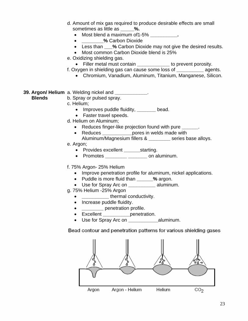
g. 75% Helium -25% Argon • __________ thermal conductivity. • Increase puddle fluidity. • ________ penetration profile. • Excellent __________penetration. • Use for Spray Arc on ___________aluminum.
24
40. Argon/ CO2 a. Argon is more expensive than _____. Blends b. Argon/CO2 blends;
• Pulse spray on stainless if the CO2 level does not exceed ____%. • Spray transfer and pulsed spray transfer requires the CO2 levels
below _____%. • CO2 levels ____________ = heat input & chance of burn through. • Short Circuit Transfer requires minimum level of ____% CO2.
c. 75% Argon - 25% CO2. • Higher price; Commonly called “______ ____”. • Most commonly used by home hobbyist and________ fabricators. • Advantages for Carbon Steel; Lower levels of spatter, more
_________arc = improved weld bead appearance. • More narrower but _______ penetration than 100%CO2. • Limited to short circuit and ___________ transfer.
d. 80% argon – 20% CO2. • Reduces ________. • Enhance weld bead appearance on _________steel applications.
e. 82%Argon – 18% CO2. • Effective limit for ______ _______ with CO2. • Popular European blend. • Broad arc; good penetration profile. • Good for short arc and _____ (surface tension transfer)
applications. f. 85% Argon - 15% CO2.
• Higher price, • Most commonly used by fabricators. • Combination of lower spatter levels, excellent penetration for
heavier plate & steels with heavier ____________. • Increased sidewall fusion. • Improved toe ________. • _______ heat for welding parts = less risk of burn through in short
circuit transfer. • Used for short circuit, globular, pulse and _________ transfer.
g. 90% Argon – 10% CO2. • __________ price. • Most commonly used by fabricators. • Combination of lower spatter levels, good penetration, used for
________ variety of steel plate applications. • Broader penetration; reduces the depth of the _____________
penetration exhibited by argon + oxygen blends. • Used for short circuit, globular, pulse and ________ transfer.
(Yuba College – Spray & Pulse Spray) h. 95% Argon – 5 % CO2.
• Pulsed spray w/________ ________ wire. • ___% CO2 improves puddle fluidity. • Better for heavier fabrication than ___% CO2 blends.
25
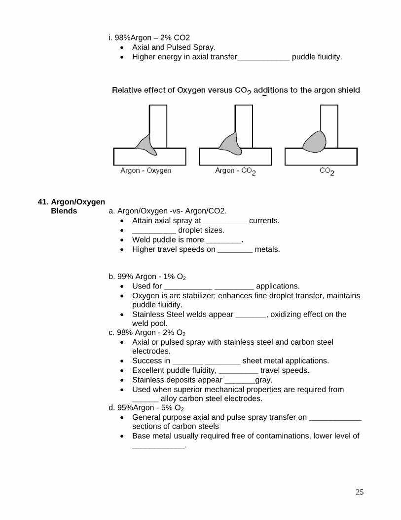
i. 98%Argon – 2% CO2 • Axial and Pulsed Spray. • Higher energy in axial transfer____________ puddle fluidity.
41. Argon/Oxygen Blends a. Argon/Oxygen -vs- Argon/CO2.
• Attain axial spray at __________ currents. • __________ droplet sizes. • Weld puddle is more ________. • Higher travel speeds on ________ metals.
b. 99% Argon - 1% O2
• Used for ___________ _________ applications. • Oxygen is arc stabilizer; enhances fine droplet transfer, maintains
puddle fluidity. • Stainless Steel welds appear _______, oxidizing effect on the
weld pool. c. 98% Argon - 2% O2
• Axial or pulsed spray with stainless steel and carbon steel electrodes.
• Success in _______ ________ sheet metal applications. • Excellent puddle fluidity, _________ travel speeds. • Stainless deposits appear _______gray. • Used when superior mechanical properties are required from
______ alloy carbon steel electrodes. d. 95%Argon - 5% O2
• General purpose axial and pulse spray transfer on ____________ sections of carbon steels
• Base metal usually required free of contaminations, lower level of ____________.
26
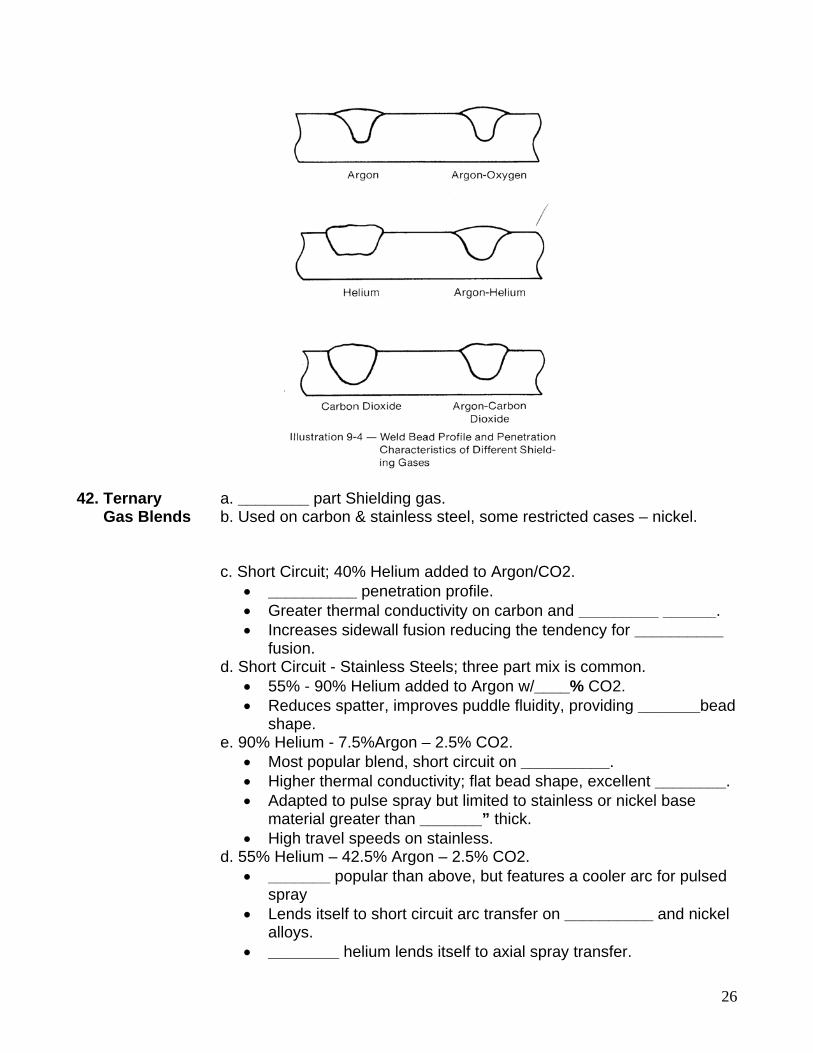
42. Ternary a. ________ part Shielding gas. Gas Blends b. Used on carbon & stainless steel, some restricted cases – nickel. c. Short Circuit; 40% Helium added to Argon/CO2.
• __________ penetration profile. • Greater thermal conductivity on carbon and _________ ______. • Increases sidewall fusion reducing the tendency for __________
fusion. d. Short Circuit - Stainless Steels; three part mix is common.
• 55% - 90% Helium added to Argon w/____% CO2. • Reduces spatter, improves puddle fluidity, providing _______bead
shape. e. 90% Helium - 7.5%Argon – 2.5% CO2.
• Most popular blend, short circuit on __________. • Higher thermal conductivity; flat bead shape, excellent ________. • Adapted to pulse spray but limited to stainless or nickel base
material greater than _______” thick. • High travel speeds on stainless.
d. 55% Helium – 42.5% Argon – 2.5% CO2. • _______ popular than above, but features a cooler arc for pulsed
spray • Lends itself to short circuit arc transfer on __________ and nickel
alloys. • ________ helium lends itself to axial spray transfer.
27
e. 38% Helium – 65%Argon – 7% CO2. • Short circuit arc transfer on ______ and low alloy steel
applications. • Used on ________ for open root welding. • High thermal conductivity; _________ penetration profile, reduces
tendency to cold lap. f. 90%Argon - 8% CO2 – 2% oxygen
• Short circuiting, pulsed spray and axial spray modes on carbon steel applications.
• High inert gas content ___________ spatter. 43. Filler Materials a. Bare or Copper Clad solid continuous wire electrode.
• Copper acts as a _____________. • Protects electrode from moisture/_____________. • Aids in conductivity.
b. AWS Classifications (American Welding Society) • A5.7 – Copper and Copper alloys • A5.9 – Stainless steels • A5.10 – Aluminum and aluminum alloys • A5.14 – Nickel and nickel alloys • A5.16 – Titanium and titanium alloys • A5.18 – Carbon steels • A5.19 - Magnesium alloys • A5.24 – Zirconium and Zirconium alloys • A5.28 – Low alloy steels
c. Wire Rolls, Spools, Reels. • Standard hole sizes (___”). • 4, 8, 12, 14” spools. (12” most common size) • 12, 14, 16” coils (mount on reels) • Drum size barrels.
d. Cast & Helix • Cast; ___________ of one circular form of wire as it lies flat and
loose. • Helix; how high one end of wire is above other end when lying flat. • Cast & Helix; insures contact between wire electrode and
________ _______ . • Larger cast; ________ wire feed. • Helix kept small; if not - wire will ________, causing unstable arc.
44. Electrode a. Many electrode types to match service requirements. Identification b. ER 70S-X
• E – Electrode. • R – Rod. (can be used with other welding processes) • 70 – 70000lb Tensile strength. • S – Solid Wire. • X – Class or Characteristics. (s-3, s-4, s-6)
28
c. Additives • Deoxidizers and Scavengers- Silicon, Manganese, Aluminum.
45. Wire Care a. Packaging – foil wrapped, __________ ________. b. Use in a timely manner once opened. c. Protect from atmosphere/___________. 46. Choosing a. Parent material; electrode should match mechanical and chemical Wire properties of parent (_______) material. b. Deposition requirement.
• Smaller wire - ________ wire speed for comparable depositions of larger diameter wires.
• Diameter; .035” and ._____”, most common production wire sizes. c. Tensile strength. d. Brand; inexpensive not always better. e. Shielding Gas. f. Condition of ________ to be welded. (rust, millscale, dirt) 47. Steel a. Many electrode types, brand names available. Electrode b. All must conform to _______ standards. Wires c. Wire diameters; 0.024” – ______”, weld 24 gauge to heavy plate. d. ER70S-2
• Once preferred electrode for GTAW. (replaced by S-3 & ____) • _________ Deoxidized; (triple deoxidized wire) Silicon,
Manganese & Aluminum, Zirconium, Titanium. • Welds all grades of ________ _______ & some low alloy steels. • Excellent ____ w/75% A -25% CO2 shielding gas. • Used w/ A-O2 mixtures & ______% CO2. • Weld rusty, dirty steel. • ________ spatter. • Yield Strength & Ultimate Tensile Strength _______ than carbon
steels. • Fast Freeze; sticky, does not _____ ____ well at toes. • Produces _________ Islands. • _________ priced than other wires.
e. ER70S-3 • Most popular GMAW electrode. • _______ deoxidizer than S-2. • Welds most carbon steels, problems w/_________steel.
(Rimmed steels differ from killed steels in that the amount of deoxidizing agent added is less. Killed steels are totally deoxidized, whereas rimmed steels are only partially deoxidized. Rimmed steels also have smooth attractive surfaces on sheet products after processing. Most steels with carbon contents lower then 0.15% are rimmed. Used for sheet steel.)
• Harsh arc w/75%A – 25%CO2 compared to S-2; ___________ spatter.
29
• Better puddle fluidity than _____, flatter weld bead. • Silicon Island removal _______ than S-2. • __________ priced.
f. ER70S-4 • More deoxidizer than _____. • Flatter & _______ bead profile than S-2 & S-3 electrodes. • Was used in __________ work. • Better results on _____________ and Rimmed steels. (*Deoxidation or "killing" is a process by which a strong deoxidizing element is added to the steel to react with the remaining oxygen in the bath to prevent any further reaction between carbon and oxygen. Completely deoxidized steels are known as “killed steels”. Produce steels with carbon contents greater then 0.25%. All forging grades of steel. Structural steels with carbon content between 0.15 to 0.25%) • Short Circuit or ________ Transfer. • More spatter than ______ electrodes.
g. ER70S-6 • High amount of Silicon/Manganese _____________. • Better for rust/____________ on steel. • No _____________ deoxidizer; puddle more fluid. • Popular electrode; (Yuba College) • _________ expensive but more versatile. • Used for Spray/Pulse Spray & Short Circuit transfer. • Good results w/Short circuit & _______%CO2.
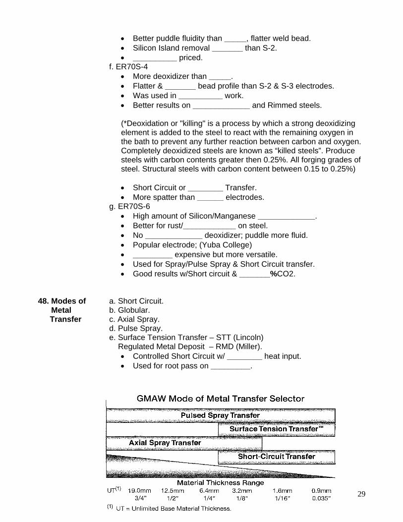
48. Modes of a. Short Circuit. Metal b. Globular. Transfer c. Axial Spray. d. Pulse Spray. e. Surface Tension Transfer – STT (Lincoln) Regulated Metal Deposit – RMD (Miller).
• Controlled Short Circuit w/ ________ heat input. • Used for root pass on _________.
30
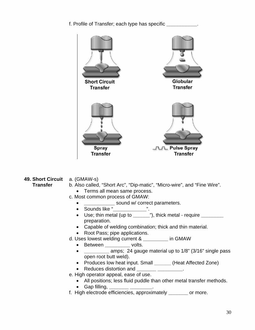
f. Profile of Transfer; each type has specific ___________. 49. Short Circuit a. (GMAW-s) Transfer b. Also called, “Short Arc”, “Dip-matic”, “Micro-wire”, and “Fine Wire”.
• Terms all mean same process. c. Most common process of GMAW:
• ___________ sound w/ correct parameters. • Sounds like “____________”. • Use; thin metal (up to ______”), thick metal - require ________
preparation. • Capable of welding combination; thick and thin material. • Root Pass; pipe applications.
d. Uses lowest welding current & _________ in GMAW • Between _________ volts. • _________ amps; 24 gauge material up to 1/8” (3/16” single pass
open root butt weld). • Produces low heat input. Small ______ (Heat Affected Zone) • Reduces distortion and _______ _________.
e. High operator appeal, ease of use. • All positions; less fluid puddle than other metal transfer methods. • Gap filling, _______ ________.
f. High electrode efficiencies, approximately _______ or more.
31
g. Fine spatter; some _______ _____ of base metal after welding. • ____________ spatter is result of improper settings.
h. Wide range of electrode diameters. • _______”, 0.030”, 0.035” and 0.045”
i. Wide range of shielding gases. • Most common; _______% Carbon Dioxide, ferrous metals. • Shielding gas type; less effect on __________ (unlike Spray).
j. Poor welding parameters/procedure control. • Limited to _______” thick material. • Lead to incomplete fusion; cold laps, ______ _______, common
problems. • Excessive spatter; leading to __________labor costs, higher
inefficiencies • Gas Drift; controlled work environment, lead to weld defects,
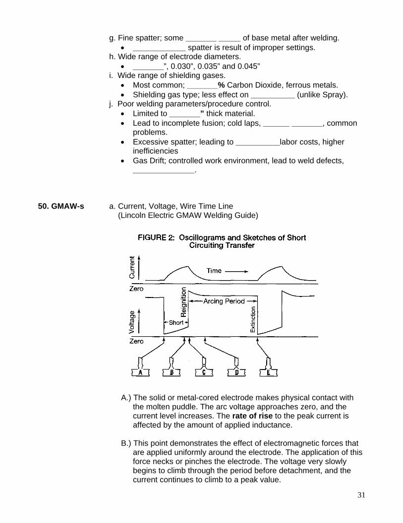
______________. 50. GMAW-s a. Current, Voltage, Wire Time Line (Lincoln Electric GMAW Welding Guide) A.) The solid or metal-cored electrode makes physical contact with the molten puddle. The arc voltage approaches zero, and the current level increases. The rate of rise to the peak current is affected by the amount of applied inductance. B.) This point demonstrates the effect of electromagnetic forces that are applied uniformly around the electrode. The application of this force necks or pinches the electrode. The voltage very slowly begins to climb through the period before detachment, and the current continues to climb to a peak value.
32
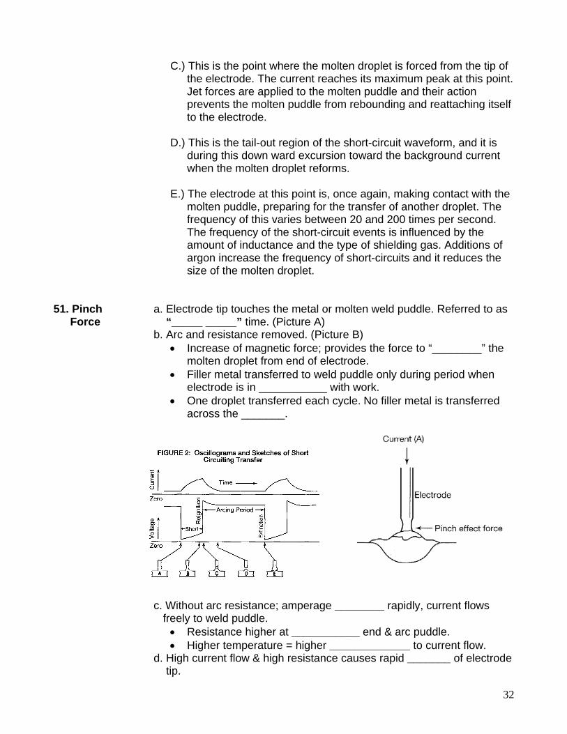
C.) This is the point where the molten droplet is forced from the tip of the electrode. The current reaches its maximum peak at this point. Jet forces are applied to the molten puddle and their action prevents the molten puddle from rebounding and reattaching itself to the electrode. D.) This is the tail-out region of the short-circuit waveform, and it is during this down ward excursion toward the background current when the molten droplet reforms. E.) The electrode at this point is, once again, making contact with the molten puddle, preparing for the transfer of another droplet. The frequency of this varies between 20 and 200 times per second. The frequency of the short-circuit events is influenced by the amount of inductance and the type of shielding gas. Additions of argon increase the frequency of short-circuits and it reduces the size of the molten droplet. 51. Pinch a. Electrode tip touches the metal or molten weld puddle. Referred to as Force “_____ _____” time. (Picture A) b. Arc and resistance removed. (Picture B)
• Increase of magnetic force; provides the force to “________” the molten droplet from end of electrode.
• Filler metal transferred to weld puddle only during period when electrode is in ___________ with work.
• One droplet transferred each cycle. No filler metal is transferred across the _______.
c. Without arc resistance; amperage ________ rapidly, current flows freely to weld puddle.
• Resistance higher at ___________ end & arc puddle. • Higher temperature = higher _____________ to current flow.
d. High current flow & high resistance causes rapid _______ of electrode tip.
33
e. Current flow increases, electrode ________ _______, explodes into a vapor when it touches base metal, establishing an arc. Called, “Arc On”. (Picture C)
• Explosion causes ___________, needs to be controlled. • Controlled with Slope and Inductance settings.
f. Arc gap reformed; voltage increases, current ___________. (Picture D) g. Decrease in current, not sufficient to melt the electrode tip as fast as it is being fed into the ______. h. Arc gap rapidly decreases until electrode tip _____________ the weld puddle. (Picture E) i. Cycle begins again. j. System properly set; short circuit rate between 20 and _______ shorts per second.
• An average welding condition, however, 90 and ______ shorts per second.
• Wire diameter; smaller wire diameter = ________ wire feed speed, more short circuits per second.
• Slope & Inductance; effects number and _________ of shorts per second.
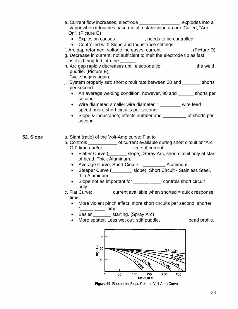
52. Slope a. Slant (ratio) of the Volt-Amp curve; Flat to _________. b. Controls ___________ of current available during short circuit or “Arc Off” time and/or ___________ time of current.
• Flatter Curve (_______ slope); Spray Arc, short circuit only at start of bead. Thick Aluminum.
• Average Curve; Short Circuit – ________, Aluminum. • Steeper Curve (________ slope); Short Circuit - Stainless Steel,
thin Aluminum. • Slope not as important for ______ ____; controls short circuit
only. c. Flat Curve; _______ current available when shorted = quick response time.
• More violent pinch effect, more short circuits per second, shorter “_____ ____” time.
• Easier _______ starting. (Spray Arc) • More spatter. Less wet out, stiff puddle, __________ bead profile.
34
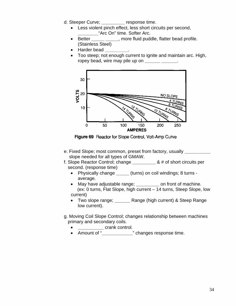
d. Steeper Curve; _________ response time. • Less violent pinch effect, less short circuits per second,
________“Arc On” time. Softer Arc. • Better _____ _____, more fluid puddle, flatter bead profile.
(Stainless Steel) • Harder bead _________. • Too steep; not enough current to ignite and maintain arc. High,
ropey bead, wire may pile up on ______ ______. e. Fixed Slope; most common, preset from factory, usually __________ slope needed for all types of GMAW. f. Slope Reactor Control; change _________ & # of short circuits per second. (response time)
• Physically change _____ (turns) on coil windings; 8 turns - average.
• May have adjustable range; _________ on front of machine. (ex: 0 turns, Flat Slope, high current – 14 turns, Steep Slope, low current) • Two slope range; ______ Range (high current) & Steep Range
low current). g. Moving Coil Slope Control; changes relationship between machines primary and secondary coils.
• __________ crank control. • Amount of “____________” changes response time.
35
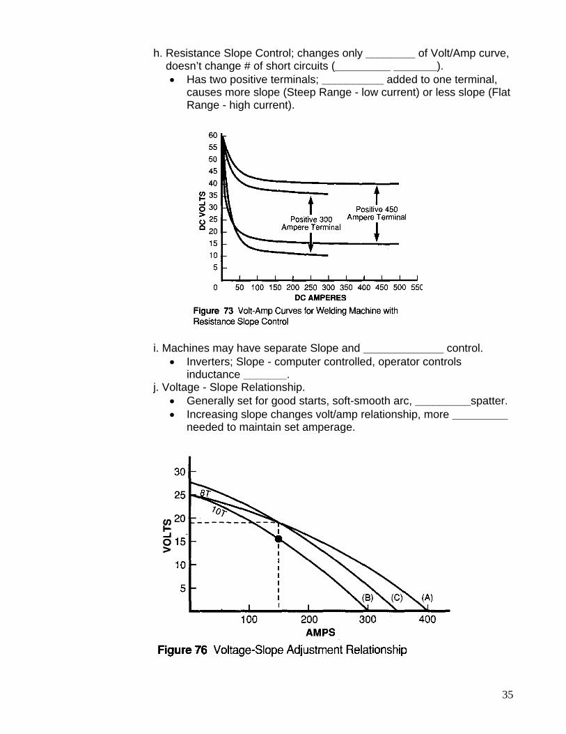
h. Resistance Slope Control; changes only ________ of Volt/Amp curve, doesn’t change # of short circuits (_________ _______).
• Has two positive terminals; __________ added to one terminal, causes more slope (Steep Range - low current) or less slope (Flat Range - high current).
i. Machines may have separate Slope and _____________ control.
• Inverters; Slope - computer controlled, operator controls inductance _______.
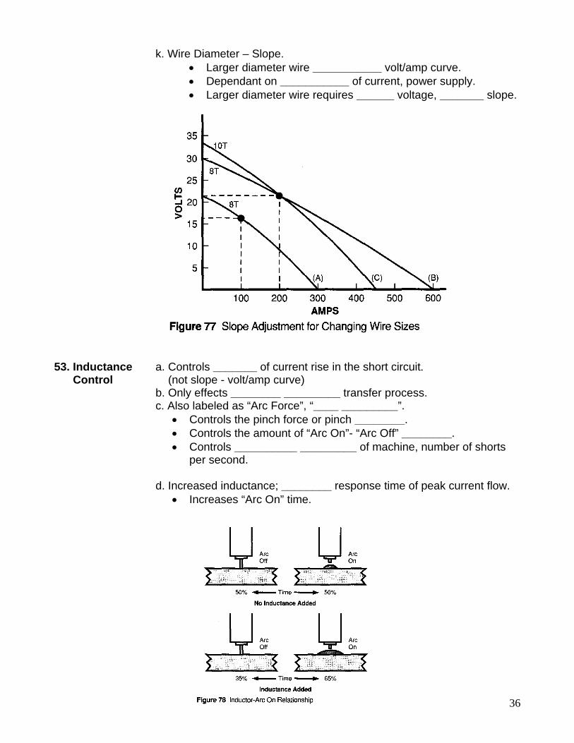
j. Voltage - Slope Relationship. • Generally set for good starts, soft-smooth arc, _________spatter. • Increasing slope changes volt/amp relationship, more _________
needed to maintain set amperage.
36
k. Wire Diameter – Slope. • Larger diameter wire ___________ volt/amp curve. • Dependant on ___________ of current, power supply. • Larger diameter wire requires ______ voltage, _______ slope.
53. Inductance a. Controls _______ of current rise in the short circuit. Control (not slope - volt/amp curve) b. Only effects ________ _________ transfer process. c. Also labeled as “Arc Force”, “____ _________”.
• Controls the pinch force or pinch ________. • Controls the amount of “Arc On”- “Arc Off” ________. • Controls __________ _________ of machine, number of shorts
per second. d. Increased inductance; ________ response time of peak current flow.
• Increases “Arc On” time.
37
• _____________ number of shorts per second. • Increases droplet size, more _________ transferred through each
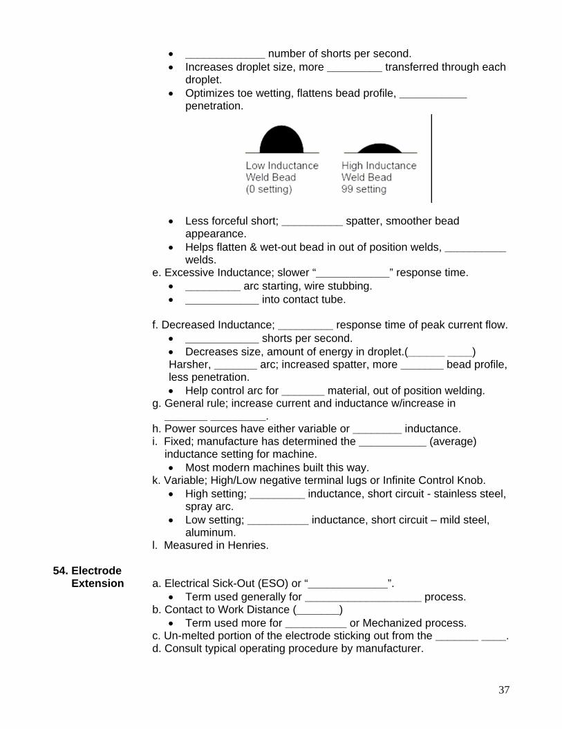
droplet. • Optimizes toe wetting, flattens bead profile, ___________
penetration.
• Less forceful short; __________ spatter, smoother bead appearance.
• Helps flatten & wet-out bead in out of position welds, __________ welds.
e. Excessive Inductance; slower “____________” response time. • _________ arc starting, wire stubbing. • ____________ into contact tube.
f. Decreased Inductance; _________ response time of peak current flow.
• ____________ shorts per second. • Decreases size, amount of energy in droplet.(______ ____) Harsher, _______ arc; increased spatter, more _______ bead profile, less penetration. • Help control arc for _______ material, out of position welding.
g. General rule; increase current and inductance w/increase in _______ _________. h. Power sources have either variable or ________ inductance. i. Fixed; manufacture has determined the ___________ (average) inductance setting for machine.
• Most modern machines built this way. k. Variable; High/Low negative terminal lugs or Infinite Control Knob.
• High setting; _________ inductance, short circuit - stainless steel, spray arc.
• Low setting; __________ inductance, short circuit – mild steel, aluminum.
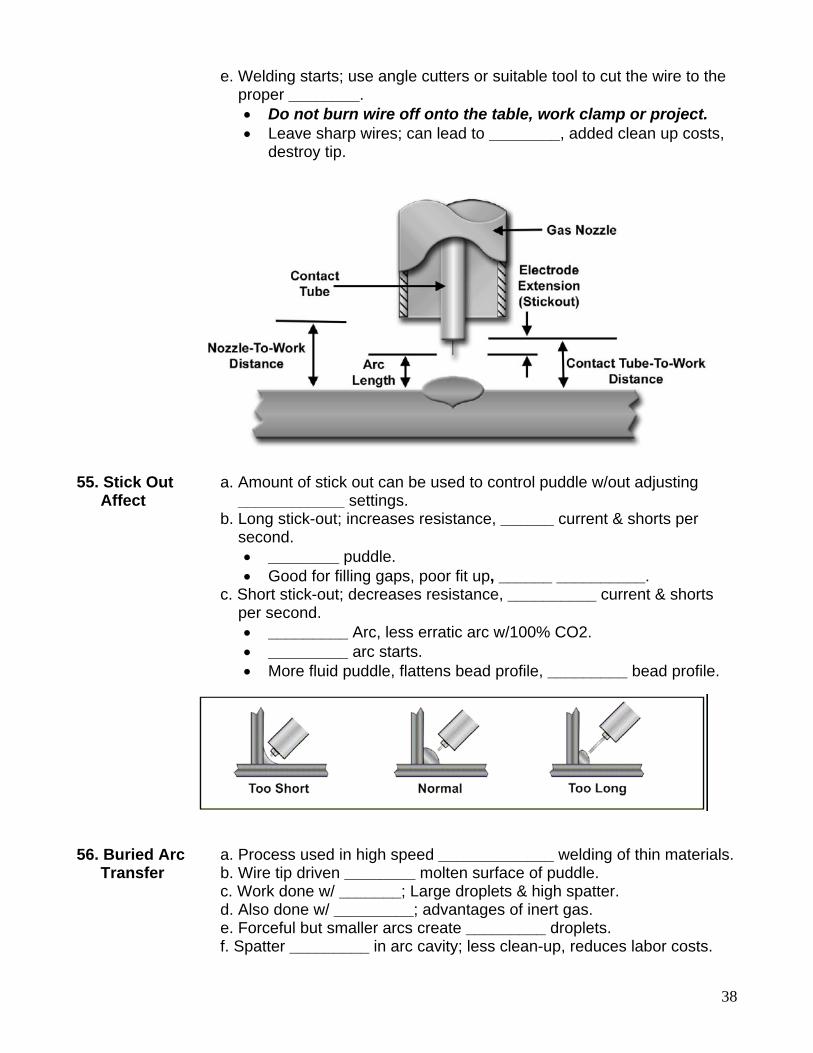
l. Measured in Henries. 54. Electrode Extension a. Electrical Sick-Out (ESO) or “_____________”.
• Term used generally for ___________________ process. b. Contact to Work Distance (_______)
• Term used more for __________ or Mechanized process. c. Un-melted portion of the electrode sticking out from the _______ ____. d. Consult typical operating procedure by manufacturer.
38
e. Welding starts; use angle cutters or suitable tool to cut the wire to the proper ________.
• Do not burn wire off onto the table, work clamp or project. • Leave sharp wires; can lead to ________, added clean up costs,
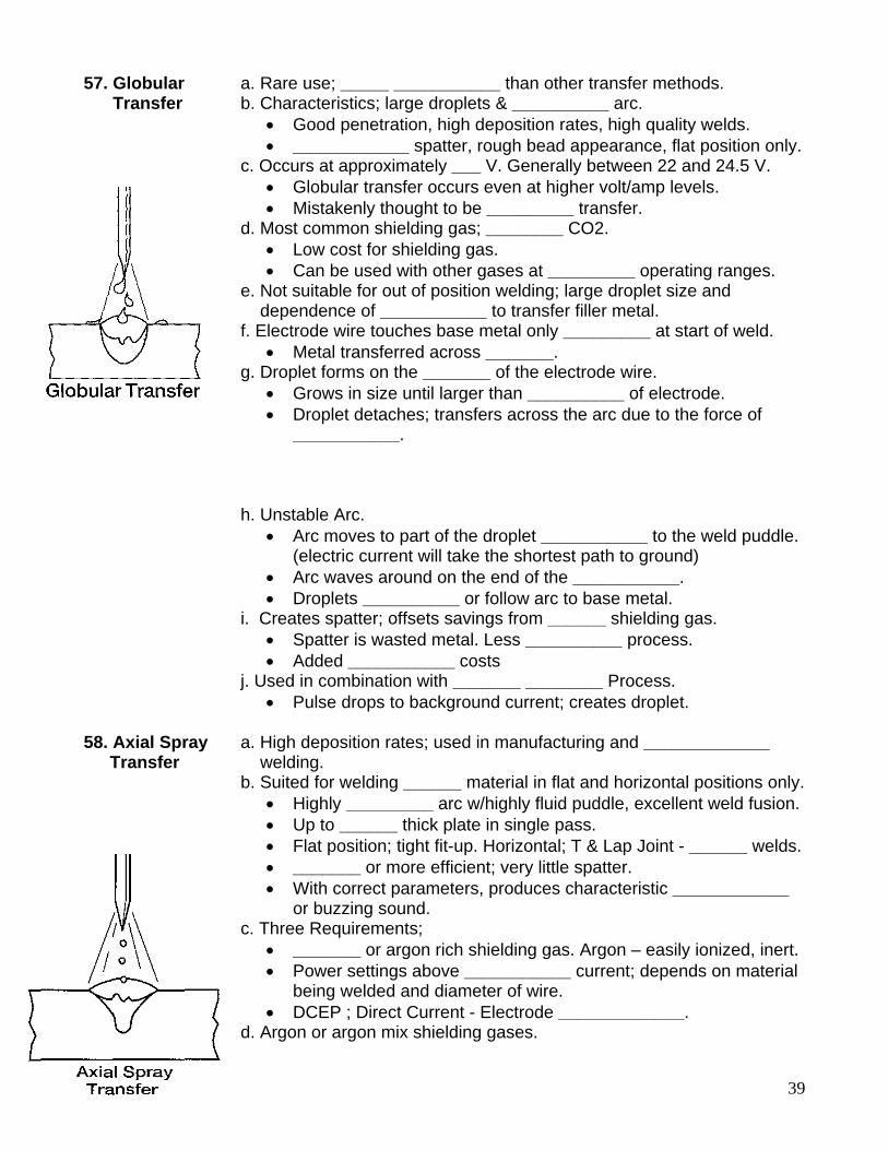
destroy tip. 55. Stick Out a. Amount of stick out can be used to control puddle w/out adjusting Affect ____________ settings. b. Long stick-out; increases resistance, ______ current & shorts per second.
• ________ puddle. • Good for filling gaps, poor fit up, ______ __________.
c. Short stick-out; decreases resistance, __________ current & shorts per second.
• _________ Arc, less erratic arc w/100% CO2. • _________ arc starts. • More fluid puddle, flattens bead profile, _________ bead profile.
56. Buried Arc a. Process used in high speed _____________ welding of thin materials. Transfer b. Wire tip driven ________ molten surface of puddle. c. Work done w/ _______; Large droplets & high spatter. d. Also done w/ _________; advantages of inert gas. e. Forceful but smaller arcs create _________ droplets. f. Spatter _________ in arc cavity; less clean-up, reduces labor costs.
39
57. Globular a. Rare use; _____ ___________ than other transfer methods. Transfer b. Characteristics; large droplets & __________ arc.
• Good penetration, high deposition rates, high quality welds. • ____________ spatter, rough bead appearance, flat position only.
c. Occurs at approximately ___ V. Generally between 22 and 24.5 V. • Globular transfer occurs even at higher volt/amp levels. • Mistakenly thought to be _________ transfer.
d. Most common shielding gas; ________ CO2. • Low cost for shielding gas. • Can be used with other gases at _________ operating ranges.
e. Not suitable for out of position welding; large droplet size and dependence of ___________ to transfer filler metal. f. Electrode wire touches base metal only _________ at start of weld.
• Metal transferred across _______. g. Droplet forms on the _______ of the electrode wire.
• Grows in size until larger than __________ of electrode. • Droplet detaches; transfers across the arc due to the force of
___________. h. Unstable Arc.
• Arc moves to part of the droplet ___________ to the weld puddle. (electric current will take the shortest path to ground)
• Arc waves around on the end of the ___________. • Droplets __________ or follow arc to base metal.
i. Creates spatter; offsets savings from ______ shielding gas. • Spatter is wasted metal. Less __________ process. • Added ___________ costs
j. Used in combination with _______ ________ Process. • Pulse drops to background current; creates droplet.
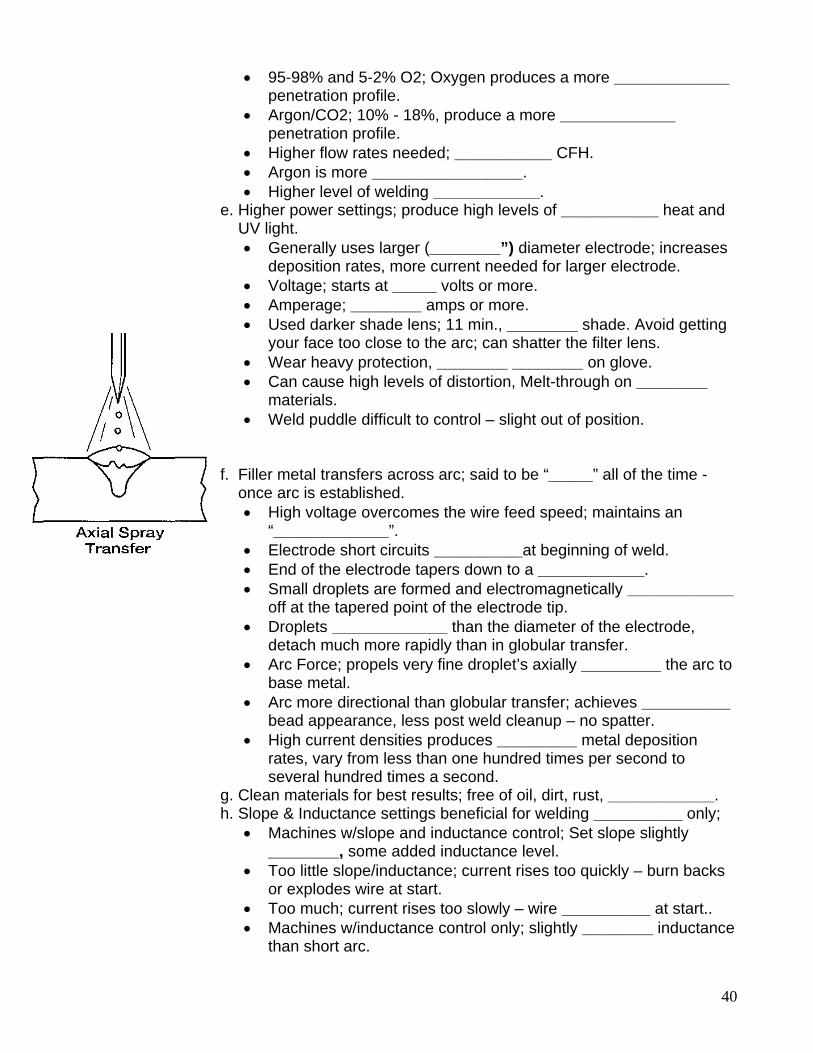
58. Axial Spray a. High deposition rates; used in manufacturing and _____________ Transfer welding. b. Suited for welding ______ material in flat and horizontal positions only.
• Highly _________ arc w/highly fluid puddle, excellent weld fusion. • Up to ______ thick plate in single pass. • Flat position; tight fit-up. Horizontal; T & Lap Joint - ______ welds. • _______ or more efficient; very little spatter. • With correct parameters, produces characteristic ____________
or buzzing sound. c. Three Requirements;
• _______ or argon rich shielding gas. Argon – easily ionized, inert. • Power settings above ___________ current; depends on material
being welded and diameter of wire. • DCEP ; Direct Current - Electrode _____________.
d. Argon or argon mix shielding gases.
40
• 95-98% and 5-2% O2; Oxygen produces a more _____________ penetration profile.
• Argon/CO2; 10% - 18%, produce a more _____________ penetration profile.
• Higher flow rates needed; ___________ CFH. • Argon is more _________________. • Higher level of welding ____________.
e. Higher power settings; produce high levels of ___________ heat and UV light.
• Generally uses larger (________”) diameter electrode; increases deposition rates, more current needed for larger electrode.
• Voltage; starts at _____ volts or more. • Amperage; ________ amps or more. • Used darker shade lens; 11 min., ________ shade. Avoid getting
your face too close to the arc; can shatter the filter lens. • Wear heavy protection, ________ ________ on glove. • Can cause high levels of distortion, Melt-through on ________
materials. • Weld puddle difficult to control – slight out of position.
f. Filler metal transfers across arc; said to be “_____” all of the time - once arc is established.
• High voltage overcomes the wire feed speed; maintains an “_____________”.
• Electrode short circuits __________at beginning of weld. • End of the electrode tapers down to a ____________. • Small droplets are formed and electromagnetically ____________
off at the tapered point of the electrode tip. • Droplets _____________ than the diameter of the electrode,
detach much more rapidly than in globular transfer. • Arc Force; propels very fine droplet’s axially _________ the arc to
base metal. • Arc more directional than globular transfer; achieves __________
bead appearance, less post weld cleanup – no spatter. • High current densities produces _________ metal deposition
rates, vary from less than one hundred times per second to several hundred times a second.
g. Clean materials for best results; free of oil, dirt, rust, ____________. h. Slope & Inductance settings beneficial for welding __________ only;
• Machines w/slope and inductance control; Set slope slightly ________, some added inductance level.
• Too little slope/inductance; current rises too quickly – burn backs or explodes wire at start.
• Too much; current rises too slowly – wire __________ at start.. • Machines w/inductance control only; slightly ________ inductance
than short arc.
41
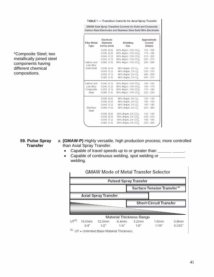
*Composite Steel; two metallically joined steel components having different chemical compositions.
59. Pulse Spray a. (GMAW-P) Highly versatile, high production process; more controlled Transfer than Axial Spray Transfer.
• Capable of travel speeds up to or greater than ______ _____. • Capable of continuous welding, spot welding or ___________
welding.
42
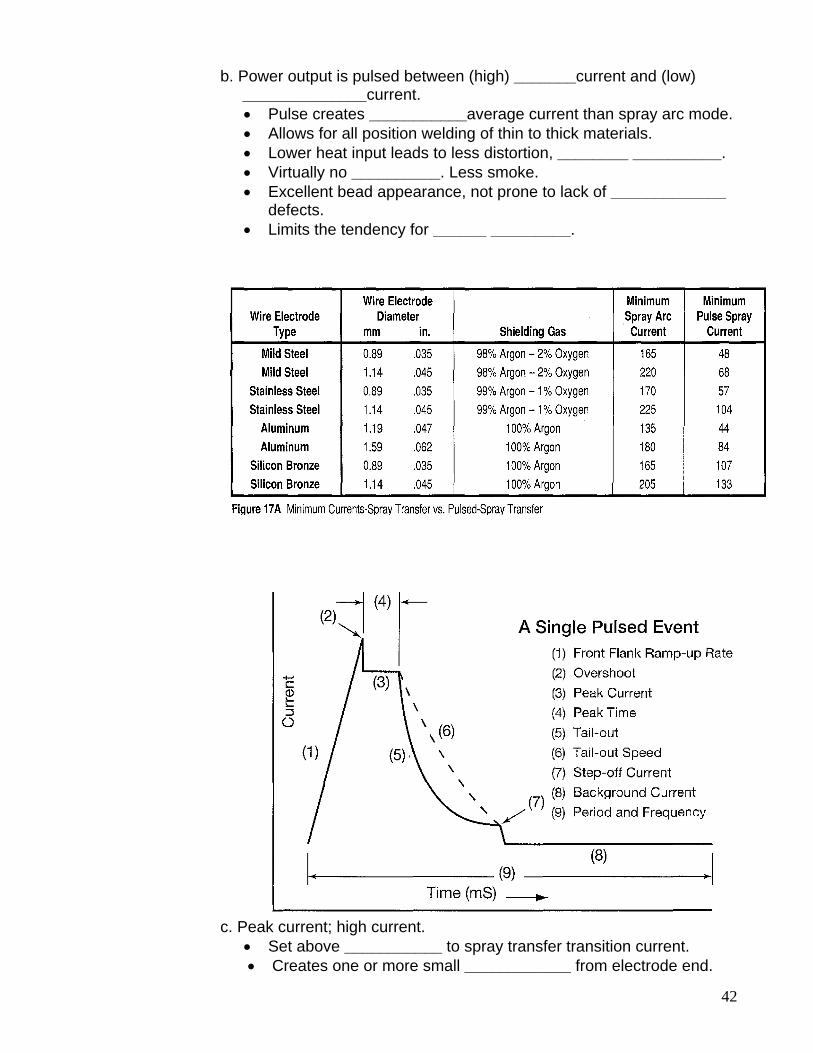
b. Power output is pulsed between (high) _______current and (low) ______________current.
• Pulse creates ___________average current than spray arc mode. • Allows for all position welding of thin to thick materials. • Lower heat input leads to less distortion, ________ __________. • Virtually no __________. Less smoke. • Excellent bead appearance, not prone to lack of _____________
defects. • Limits the tendency for ______ _________.
c. Peak current; high current.
• Set above ___________ to spray transfer transition current. • Creates one or more small ____________ from electrode end.
43
• Metal is detached and transferred across ____ – no short circuit. • Amplitude; current level of the power at the peak or maximum
level, expressed as _____________. d. Background current; low current.
• Sustains/stabilizes _____. • Does not cause drops to form - no _____________ transfer. • Allows puddle to slightly _________. • Time spent below transition current is about _______ seconds. • Controls overall _______ __________ into puddle.
e. Frequency; measured in pulses per ___________. • Controls number of times _________ occurs per second. • Increases in proportion to _______ ___________. • Increased frequency; arc narrows, average current increases,
droplets become __________. • Decreased frequency; arc and weld bead becomes __________.
f. Peak Current Time; amount of time the peak amperage is allowed to ______ ___. (width of pulse event)
• Expressed in ________________. • Time needed for a globule to form; about 0.1 second • Increased peak time; increased droplet size, average current,
_________________. g. Frequency and Amplitude of the pulses control the energy level of he arc, rate at which the wire _________.
• Allows welding on sheet metal or reduce metals deposition rates to allow welding in _____ ______________.
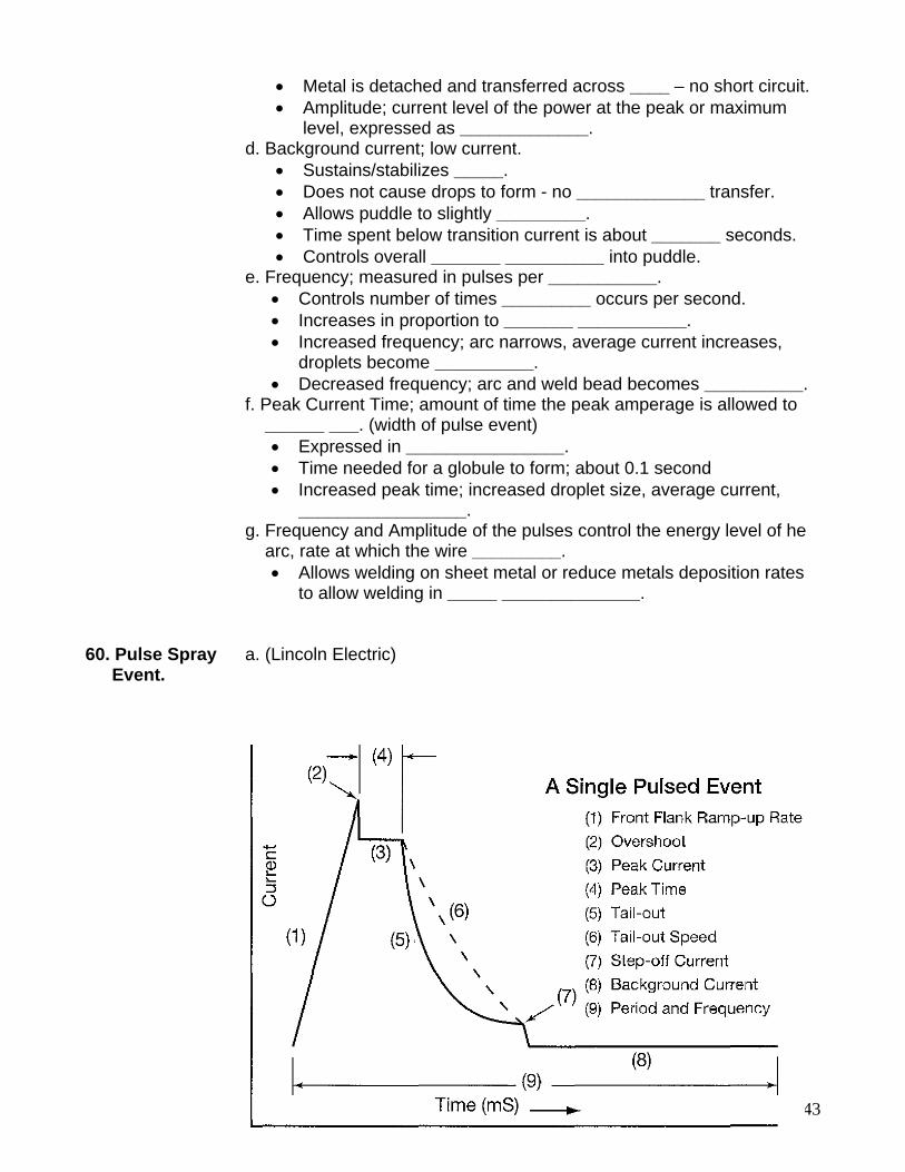
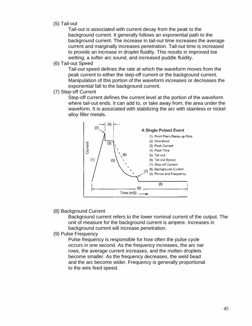
60. Pulse Spray a. (Lincoln Electric) Event.
44
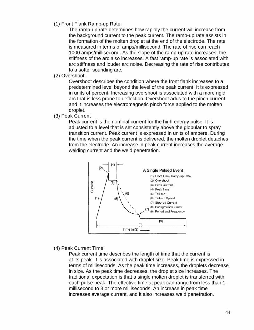
(1) Front Flank Ramp-up Rate: The ramp-up rate determines how rapidly the current will increase from the background current to the peak current. The ramp-up rate assists in the formation of the molten droplet at the end of the electrode. The rate is measured in terms of amps/millisecond. The rate of rise can reach 1000 amps/millisecond. As the slope of the ramp-up rate increases, the stiffness of the arc also increases. A fast ramp-up rate is associated with arc stiffness and louder arc noise. Decreasing the rate of rise contributes to a softer sounding arc. (2) Overshoot: Overshoot describes the condition where the front flank increases to a predetermined level beyond the level of the peak current. It is expressed in units of percent. Increasing overshoot is associated with a more rigid arc that is less prone to deflection. Overshoot adds to the pinch current and it increases the electromagnetic pinch force applied to the molten droplet. (3) Peak Current Peak current is the nominal current for the high energy pulse. It is adjusted to a level that is set consistently above the globular to spray transition current. Peak current is expressed in units of ampere. During the time when the peak current is delivered, the molten droplet detaches from the electrode. An increase in peak current increases the average welding current and the weld penetration. (4) Peak Current Time Peak current time describes the length of time that the current is at its peak. It is associated with droplet size. Peak time is expressed in terms of milliseconds. As the peak time increases, the droplets decrease in size. As the peak time decreases, the droplet size increases. The traditional expectation is that a single molten droplet is transferred with each pulse peak. The effective time at peak can range from less than 1 millisecond to 3 or more milliseconds. An increase in peak time increases average current, and it also increases weld penetration.
45
(5) Tail-out Tail-out is associated with current decay from the peak to the background current. It generally follows an exponential path to the background current. The increase in tail-out time increases the average current and marginally increases penetration. Tail-out time is increased to provide an increase in droplet fluidity. This results in improved toe wetting, a softer arc sound, and increased puddle fluidity. (6) Tail-out Speed Tail-out speed defines the rate at which the waveform moves from the peak current to either the step-off current or the background current. Manipulation of this portion of the waveform increases or decreases the exponential fall to the background current. (7) Step-off Current Step-off current defines the current level at the portion of the waveform where tail-out ends. It can add to, or take away from, the area under the waveform. It is associated with stabilizing the arc with stainless or nickel alloy filler metals. (8) Background Current Background current refers to the lower nominal current of the output. The unit of measure for the background current is ampere. Increases in background current will increase penetration. (9) Pulse Frequency Pulse frequency is responsible for how often the pulse cycle occurs in one second. As the frequency increases, the arc nar rows, the average current increases, and the molten droplets become smaller. As the frequency decreases, the weld bead and the arc become wider. Frequency is generally proportional to the wire feed speed.
46
61. Pulse Spray a. Machines can be run in Pulse or ______________ _______. Equipment b. Line Frequency Pulse Power Source; _______ generation.
• Conventional power source w/pulse. • Pulse only in frequencies that were a multiple of power source
frequency. (_____________ pulse/sec.) • Superimposed higher pulsing current with amplitude greater than
the transition current necessary for _______ _____________. • Interval between short, ______________ large droplet formation
(globular transfer). c. Pulsed Wire Feed; called “_________ __________”.
• Switches wire feed motor ___ and _____. Actually a pulsed Short Circuit Transfer.
• Pulse on and pulse off is adjustable; __________ heat input into the weld.
• Wire advances in _______; no advance – “pulse off”, puddle freezes slightly.
• May be part of GMAW-Spot Welding control, optional or built in. • Used for_____ gauge & thinner materials w/out burn through,
bridging gaps. Great for Auto-body work. d. Inverter Power Source: controls wave ______ and ___________ of pulse.
• Pulse welding current at set intervals. • High control of current, quick response time.
e. Synergic System. • Wire feed and power supply adjusted with __________ knob. • Usually Inverter power source. • Power source adjusts/adapts all variables to change in ________. • Manufacturer programs most common settings and combinations. • Additional programming possible; _________or manufacturer. • Can be programmed for wire size, wire type and shielding gas,
materials. 62. Pulse Spray Consumables a. Electrode Wire; same as for _________ ______. b. Larger wire sizes can be used.
• Electrode diameters from ______________”. • Solid Core and Metal Core wire, ______________”. • Wide range of metals and metal alloys. • Great for larger size __________ wires through conventional gun.
c. Shielding Gas; requires minimum ____% Argon rich shielding gas. d. Steel & Stainless Steel; Argon/O2 or _________________.
• Argon alone has poor wet-out, undercut & poor bead contour. e. Common gas for Steel;
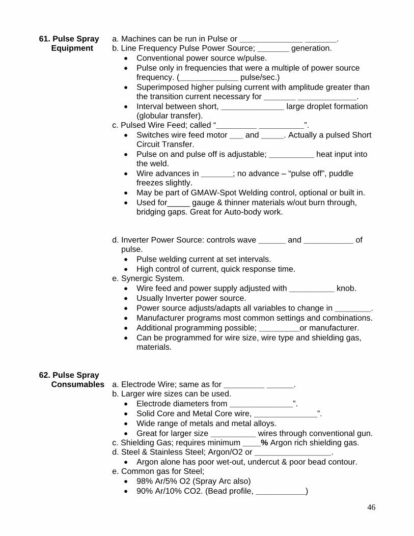
• 98% Ar/5% O2 (Spray Arc also) • 90% Ar/10% CO2. (Bead profile, ___________)
47
f. Common gas for Stainless Steel;
• 99%Ar/ 1%O2 • 98%Ar/ 2%O2(decreased corrosion resistance over ____%O2) • 90%Ar/8%CO2/2%O2. (_________)
g. Common gas for Aluminum; • 100% _________. • Helium/Argon blends; 75% – 25% blends, (____________ thick).
63. Pulse Spray a. Power sources and equipment is more __________ than conventional Disadvantages systems. b. Shielding gases are more expensive. c. Higher arc energy and light require greater _____________.
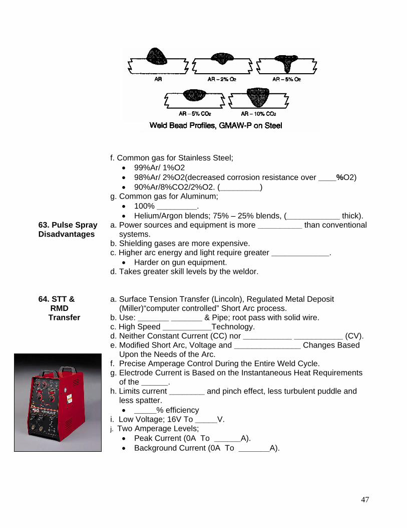
• Harder on gun equipment. d. Takes greater skill levels by the weldor. 64. STT & a. Surface Tension Transfer (Lincoln), Regulated Metal Deposit RMD (Miller)“computer controlled” Short Arc process. Transfer b. Use: _______ _______ & Pipe; root pass with solid wire. c. High Speed ___________Technology.
d. Neither Constant Current (CC) nor ___________ ___________ (CV). e. Modified Short Arc, Voltage and _______________ Changes Based Upon the Needs of the Arc. f. Precise Amperage Control During the Entire Weld Cycle. g. Electrode Current is Based on the Instantaneous Heat Requirements of the ______.
h. Limits current ________ and pinch effect, less turbulent puddle and less spatter.
• _____% efficiency i. Low Voltage; 16V To _____V. j. Two Amperage Levels;
• Peak Current (0A To ______A). • Background Current (0A To _______A).
48
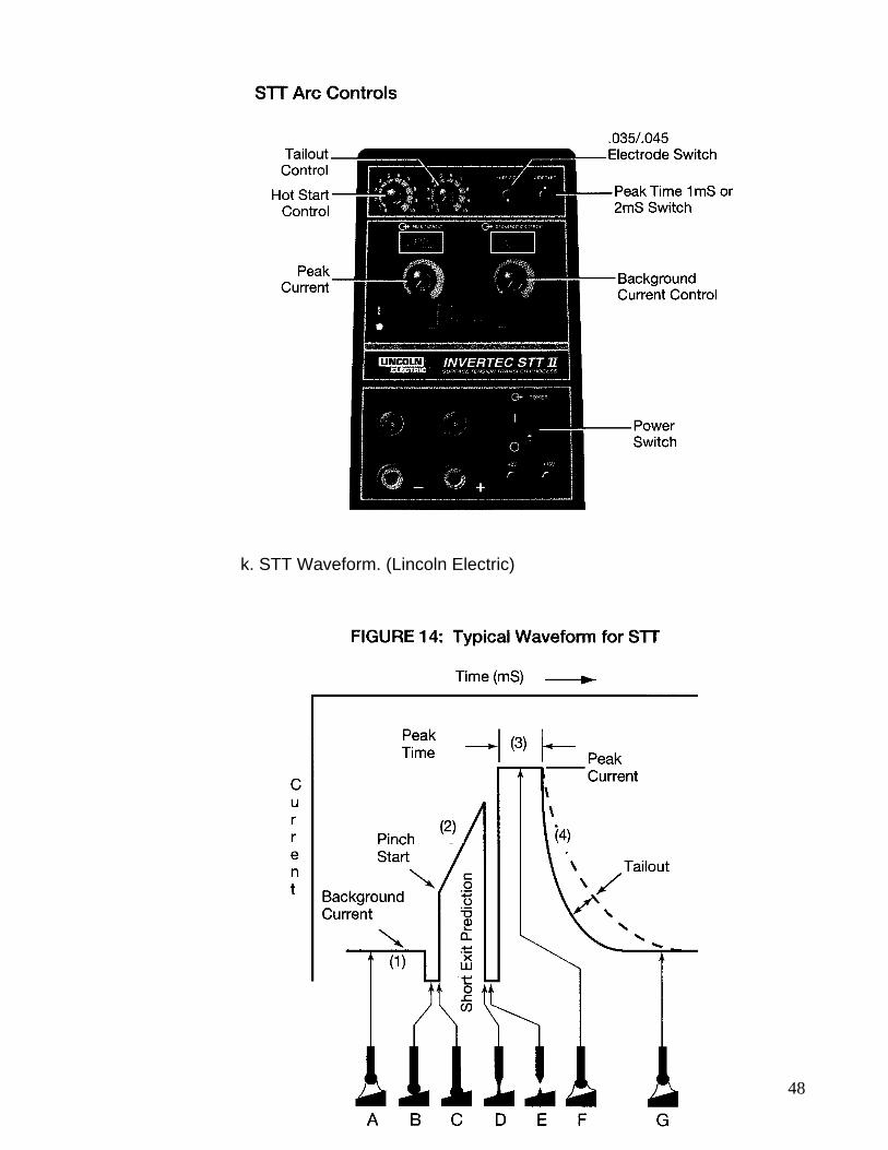
k. STT Waveform. (Lincoln Electric)
49
A. The molten tip of the electrode makes physical contact with the molten pool at the background current level. B. The background current is reduced to a lower level to prevent the occurrence of a premature molten droplet detachment. C. The current then ramps up quickly to a point where the pinch force associated with the rise in current (electromagnetic force) starts to neck down the molten column of the electrode. The power source at this point begins to monitor the changes in voltage over time as it relates to the necking of the molten droplet. The molten metal is still in contact with the molten weld pool. Via the sensing lead, the power source references the observed voltage, and continuously compares the new voltage value to the previous voltage value. D. At the point where the molten metal is about to disconnect from the end of the electrode, the power source reduces the current to a lower than back ground current level. At this point in the waveform, surface tension forces collapse and the molten droplet transfers to the weld pool. This controlled detachment of the molten droplet is free of spatter. E. The power source then rises to the peak current level where a new droplet begins to form. Anode jet forces depress the molten weld puddle to prevent it from reattaching to the electrode. On its descent to the background current, the tail-out current provides the molten droplet with additional energy. The added energy increases puddle fluidity, and the result is improved wetting at the toes of the weld. F. A plasma boost is applied which provides the energy to re-establish the arc length, provide a new molten droplet, and force the molten puddle away from the molten droplet. The length of time is nominally 1 mS for carbon steel electrodes and 2 mS for both stainless and nickel alloyed filler metals.
G. The tail-out region is employed in applications where the energy added to the molten droplet provides faster travel speeds and improved finished weld wetting action at the toes. In most pipe root applications, this value is kept to a minimum.
l. Peak Current Control; responsible for establishing the ______ __________. • Provides sufficient energy to preheat the work piece, insures good
______________. • Set too high; molten droplets will become too __________. • Molten droplet formed should ________ times electrode diameter.
m. Background Current; responsible for providing weld ______________ into the base material.
• Responsible for __________ heat input into weld. • Controls level of weld penetration, effects ________ of molten droplet.
n. Tail-out Current; adds energy to the molten droplet, increases droplet ____________.
• Applies added energy without effecting droplet _________. • Increasing tail-out current increases puddle fluidity, faster travel speeds,
improves weld _______ wetting.
50
p. Wire Electrode Size. • Typically larger diameters, _________” and larger.
q. Shielding Gases. • 100% CO2. • 75% Ar / 25% _______.
r. Advantages. • Controlled Heat Input. • Minimal ____________. • Minimal ____________. • All Positions. • Low Cost Gas. • Good ____________. • Handles Poor Fit Up.
s. Limitations. • _________ _______ of equipment. • Limited to a Modified Short Circuit Mode.
51
WELD JOINTS & TYPES 1. Weld Terms a. Weld puddle; molten metal created by the arc or flame while welding.
b. Weld bead; metal deposited by consuming the electrode or rod and depositing it combined with the base metal. c. Reinforcement; two types.
• Face reinforcement; amount of weld bead above the surface of base metal after welding. Usually limited to 1/8”.
• Root reinforcement; amount weld metal excess in the root of the joint. Usually limited to 1/16”.
d. Weld puddle; Molten metal created by the arc or flame while welding. e. Weld bead; Metal deposited by consuming the electrode or rod and depositing it combined with the base metal. f. Partial Joint Penetration (PJP).
• Used when maximum joint strength is not necessary. • Cost less.
g. Complete Joint Penetration (CJP). • Used when maximum joint strength is necessary.
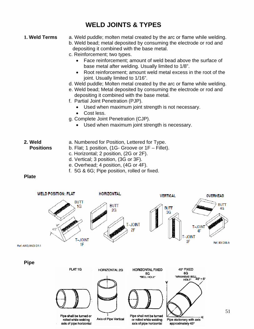
2. Weld a. Numbered for Position, Lettered for Type. Positions b. Flat; 1 position, (1G- Groove or 1F – Fillet). c. Horizontal; 2 position, (2G or 2F). d. Vertical; 3 position, (3G or 3F). e. Overhead; 4 position, (4G or 4F). f. 5G & 6G; Pipe position, rolled or fixed. Plate
Pipe
52
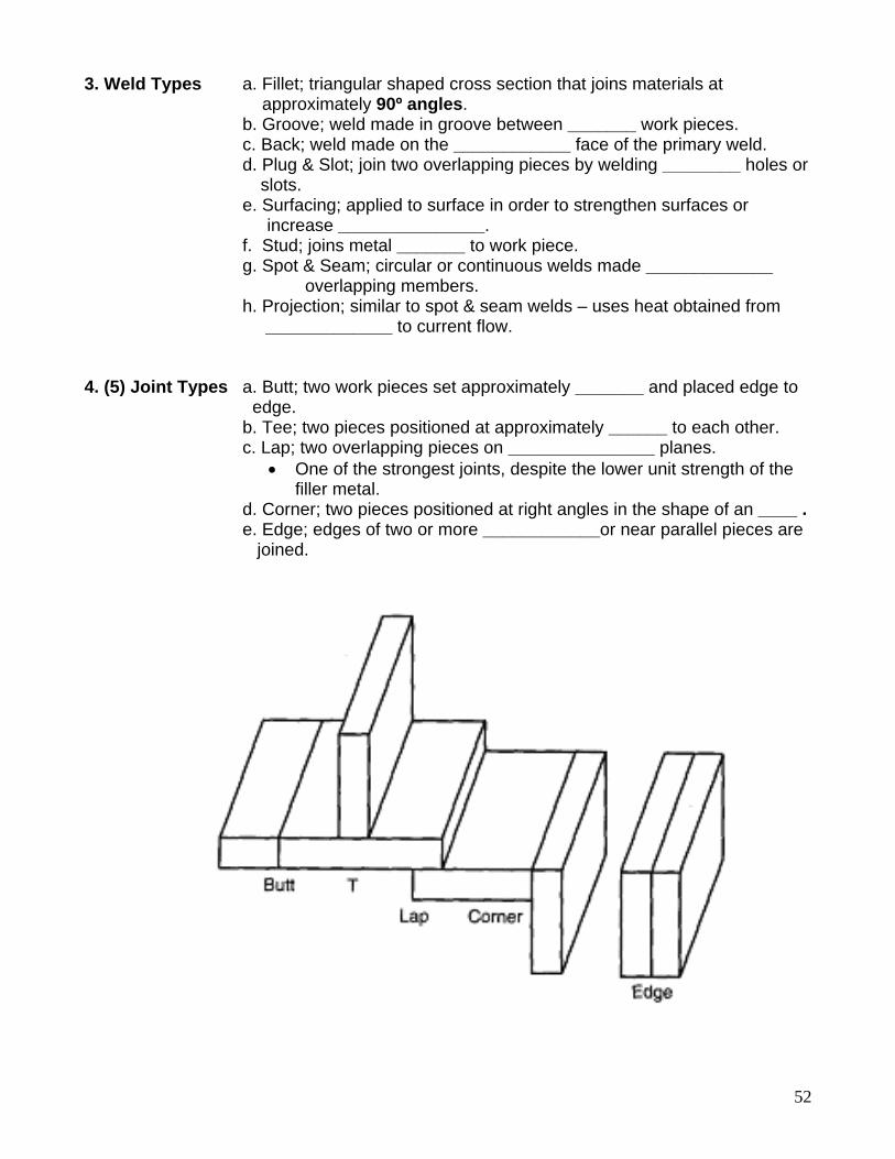
3. Weld Types a. Fillet; triangular shaped cross section that joins materials at approximately 90º angles. b. Groove; weld made in groove between _______ work pieces. c. Back; weld made on the ____________ face of the primary weld. d. Plug & Slot; join two overlapping pieces by welding ________ holes or slots. e. Surfacing; applied to surface in order to strengthen surfaces or increase _______________. f. Stud; joins metal _______ to work piece. g. Spot & Seam; circular or continuous welds made _____________ overlapping members. h. Projection; similar to spot & seam welds – uses heat obtained from _____________ to current flow. 4. (5) Joint Types a. Butt; two work pieces set approximately _______ and placed edge to edge. b. Tee; two pieces positioned at approximately ______ to each other. c. Lap; two overlapping pieces on _______________ planes.
• One of the strongest joints, despite the lower unit strength of the filler metal.
d. Corner; two pieces positioned at right angles in the shape of an ____ . e. Edge; edges of two or more ____________or near parallel pieces are joined.
53
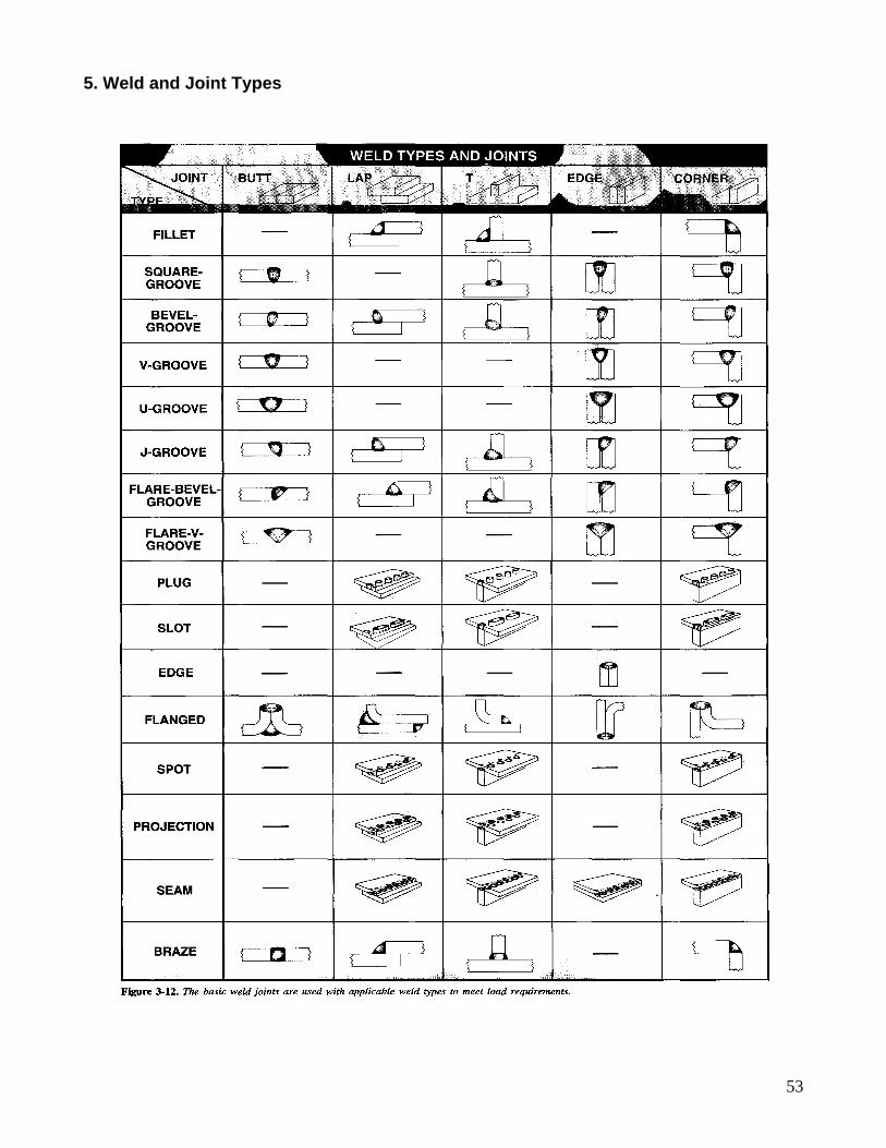
5. Weld and Joint Types
54
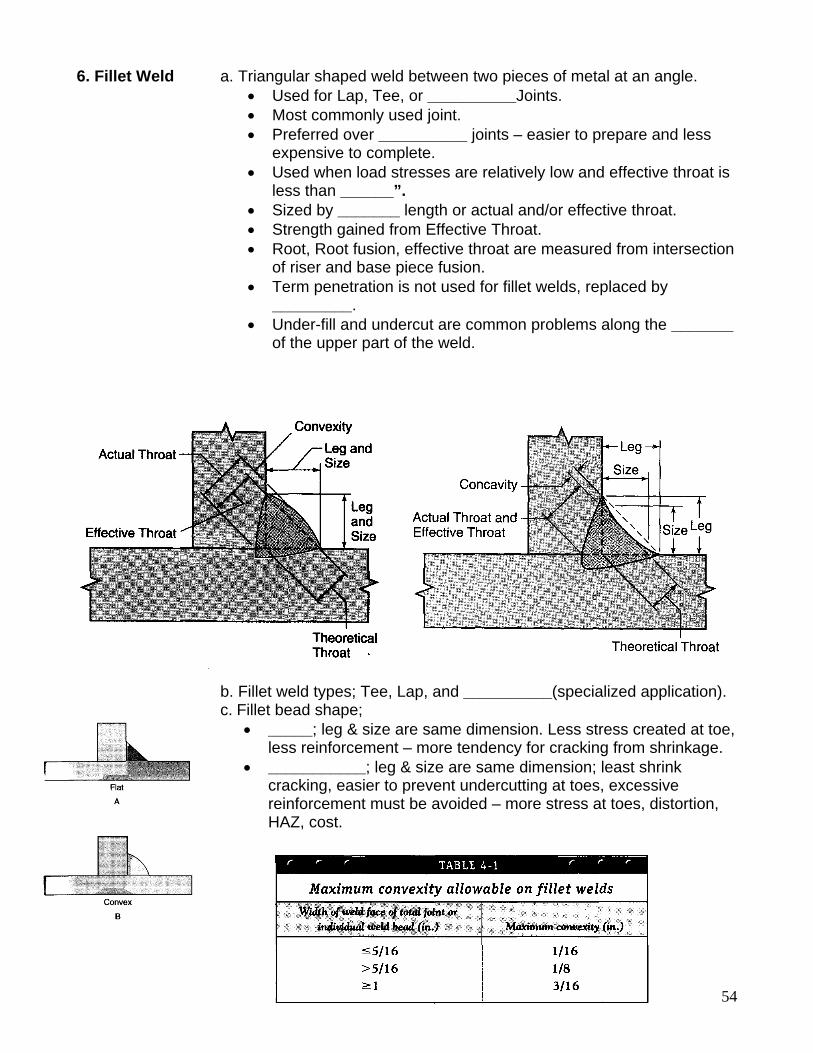
6. Fillet Weld a. Triangular shaped weld between two pieces of metal at an angle. • Used for Lap, Tee, or __________Joints. • Most commonly used joint. • Preferred over __________ joints – easier to prepare and less
expensive to complete. • Used when load stresses are relatively low and effective throat is
less than ______”. • Sized by _______ length or actual and/or effective throat. • Strength gained from Effective Throat. • Root, Root fusion, effective throat are measured from intersection
of riser and base piece fusion. • Term penetration is not used for fillet welds, replaced by
_________. • Under-fill and undercut are common problems along the _______
of the upper part of the weld.
b. Fillet weld types; Tee, Lap, and __________(specialized application). c. Fillet bead shape;
• _____; leg & size are same dimension. Less stress created at toe, less reinforcement – more tendency for cracking from shrinkage.
• ___________; leg & size are same dimension; least shrink cracking, easier to prevent undercutting at toes, excessive reinforcement must be avoided – more stress at toes, distortion, HAZ, cost.
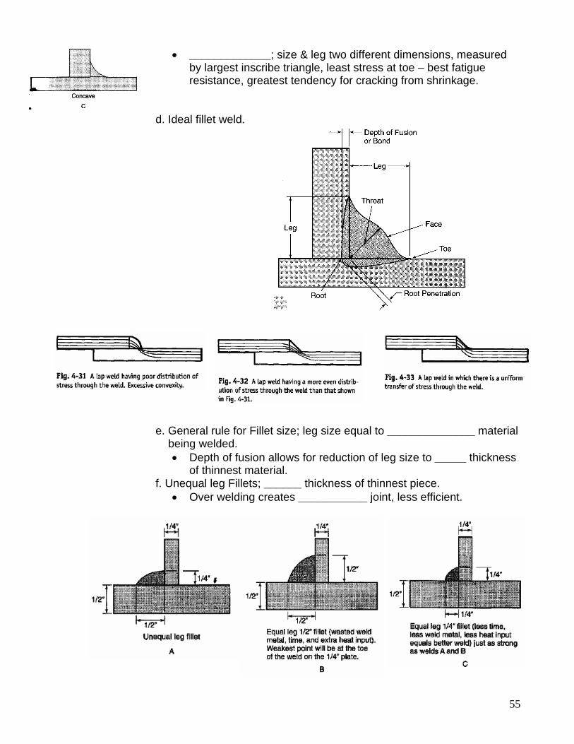
55
• _____________; size & leg two different dimensions, measured by largest inscribe triangle, least stress at toe – best fatigue resistance, greatest tendency for cracking from shrinkage.
d. Ideal fillet weld.
e. General rule for Fillet size; leg size equal to ______________ material being welded.
• Depth of fusion allows for reduction of leg size to _____ thickness of thinnest material.
f. Unequal leg Fillets; ______ thickness of thinnest piece. • Over welding creates ___________ joint, less efficient.
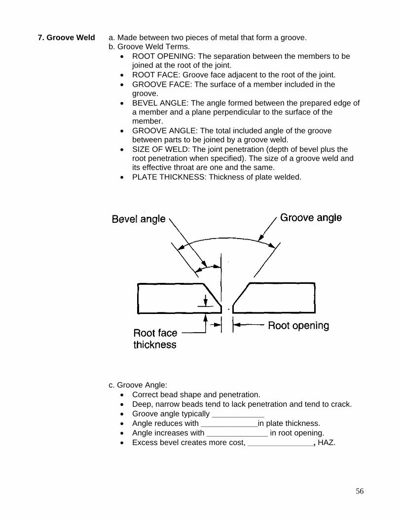
56
7. Groove Weld a. Made between two pieces of metal that form a groove. b. Groove Weld Terms.
• ROOT OPENING: The separation between the members to be joined at the root of the joint.
• ROOT FACE: Groove face adjacent to the root of the joint. • GROOVE FACE: The surface of a member included in the
groove. • BEVEL ANGLE: The angle formed between the prepared edge of
a member and a plane perpendicular to the surface of the member.
• GROOVE ANGLE: The total included angle of the groove between parts to be joined by a groove weld.
• SIZE OF WELD: The joint penetration (depth of bevel plus the root penetration when specified). The size of a groove weld and its effective throat are one and the same.
• PLATE THICKNESS: Thickness of plate welded. c. Groove Angle:
• Correct bead shape and penetration. • Deep, narrow beads tend to lack penetration and tend to crack. • Groove angle typically ____________ • Angle reduces with _____________in plate thickness. • Angle increases with ______________ in root opening. • Excess bevel creates more cost, _______________, HAZ.
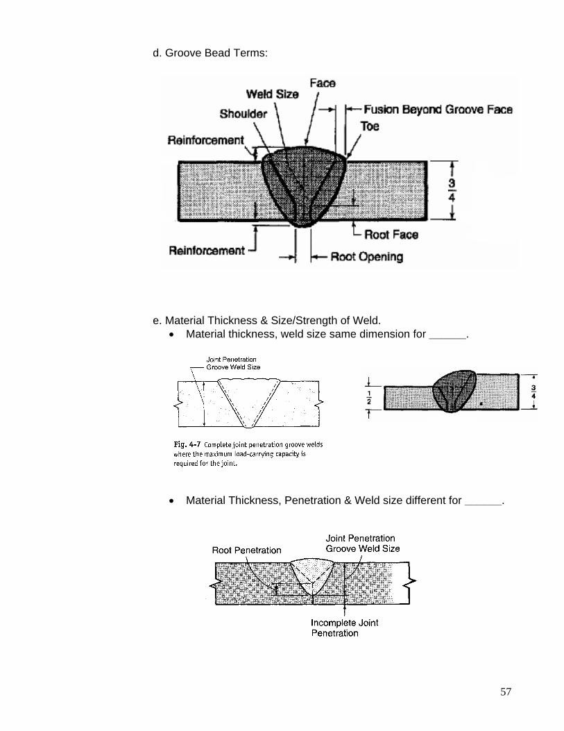
57
d. Groove Bead Terms: e. Material Thickness & Size/Strength of Weld.
• Material thickness, weld size same dimension for ______.
• Material Thickness, Penetration & Weld size different for ______.
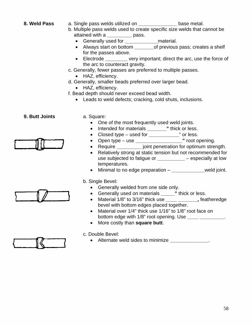
58
8. Weld Pass a. Single pass welds utilized on ______________ base metal. b. Multiple pass welds used to create specific size welds that cannot be attained with a _________ pass.
• Generally used for ____________material. • Always start on bottom _______of previous pass; creates a shelf
for the passes above. • Electrode ________ very important; direct the arc, use the force of
the arc to counteract gravity. c. Generally, fewer passes are preferred to multiple passes.
• HAZ, efficiency. d. Generally, smaller beads preferred over larger bead.
• HAZ, efficiency. f. Bead depth should never exceed bead width.
• Leads to weld defects; cracking, cold shuts, inclusions. 9. Butt Joints a. Square:
• One of the most frequently used weld joints. • Intended for materials _______” thick or less. • Closed type – used for ___________” or less. • Open type – use _________________” root opening. • Require _________ joint penetration for optimum strength. • Relatively strong at static tension but not recommended for
use subjected to fatigue or __________ – especially at low temperatures.
• Minimal to no edge preparation – ____________weld joint.
b. Single Bevel: • Generally welded from one side only. • Generally used on materials _____” thick or less. • Material 1/8” to 3/16” thick use ____ _______, featheredge
bevel with bottom edges placed together. • Material over 1/4” thick use 1/16” to 1/8” root face on
bottom edge with 1/8” root opening. Use ____ _________. • More costly than square butt.
c. Double Bevel:
• Alternate weld sides to minimize ______________.
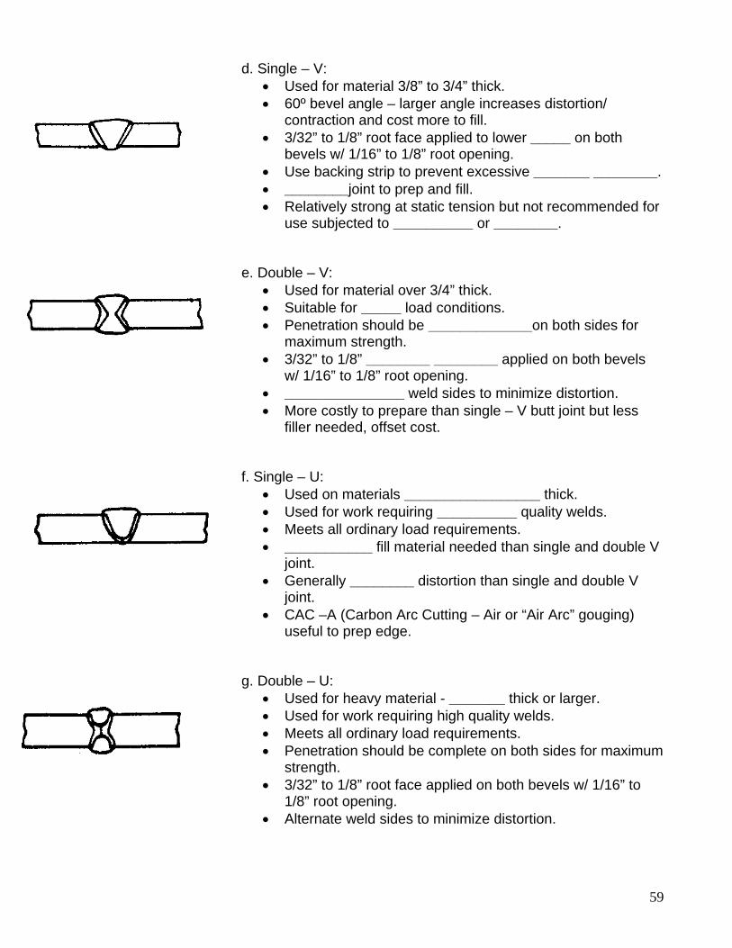
59
d. Single – V: • Used for material 3/8” to 3/4” thick. • 60º bevel angle – larger angle increases distortion/
contraction and cost more to fill. • 3/32” to 1/8” root face applied to lower _____ on both
bevels w/ 1/16” to 1/8” root opening. • Use backing strip to prevent excessive _______ ________. • ________joint to prep and fill. • Relatively strong at static tension but not recommended for
use subjected to __________ or ________.
e. Double – V: • Used for material over 3/4” thick. • Suitable for _____ load conditions. • Penetration should be _____________on both sides for
maximum strength. • 3/32” to 1/8” ________ ________ applied on both bevels
w/ 1/16” to 1/8” root opening. • _______________ weld sides to minimize distortion. • More costly to prepare than single – V butt joint but less
filler needed, offset cost.
f. Single – U: • Used on materials _________________ thick. • Used for work requiring __________ quality welds. • Meets all ordinary load requirements. • ___________ fill material needed than single and double V
joint. • Generally ________ distortion than single and double V
joint. • CAC –A (Carbon Arc Cutting – Air or “Air Arc” gouging)
useful to prep edge.
g. Double – U:
• Used for heavy material - _______ thick or larger. • Used for work requiring high quality welds. • Meets all ordinary load requirements. • Penetration should be complete on both sides for maximum
strength. • 3/32” to 1/8” root face applied on both bevels w/ 1/16” to
1/8” root opening. • Alternate weld sides to minimize distortion.
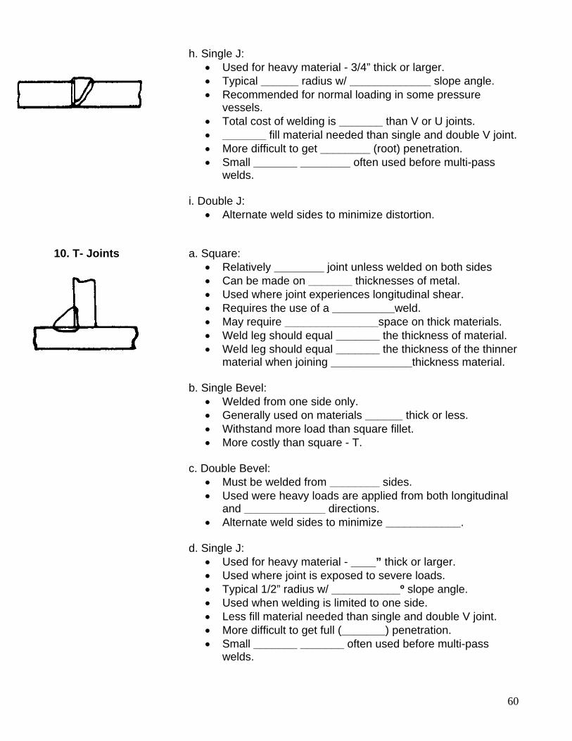
60
h. Single J: • Used for heavy material - 3/4” thick or larger. • Typical ______ radius w/ _____________ slope angle. • Recommended for normal loading in some pressure
vessels. • Total cost of welding is _______ than V or U joints. • _______ fill material needed than single and double V joint. • More difficult to get ________ (root) penetration. • Small _______ ________ often used before multi-pass
welds. i. Double J:
• Alternate weld sides to minimize distortion. 10. T- Joints a. Square:
• Relatively ________ joint unless welded on both sides • Can be made on _______ thicknesses of metal. • Used where joint experiences longitudinal shear. • Requires the use of a __________weld. • May require _______________space on thick materials. • Weld leg should equal _______ the thickness of material. • Weld leg should equal _______ the thickness of the thinner
material when joining _____________thickness material.
b. Single Bevel: • Welded from one side only. • Generally used on materials ______ thick or less. • Withstand more load than square fillet. • More costly than square - T.
c. Double Bevel:
• Must be welded from ________ sides. • Used were heavy loads are applied from both longitudinal
and _____________ directions. • Alternate weld sides to minimize ____________.
d. Single J:
• Used for heavy material - ____” thick or larger. • Used where joint is exposed to severe loads. • Typical 1/2” radius w/ ___________º slope angle. • Used when welding is limited to one side. • Less fill material needed than single and double V joint. • More difficult to get full (_______) penetration. • Small _______ _______ often used before multi-pass
welds.
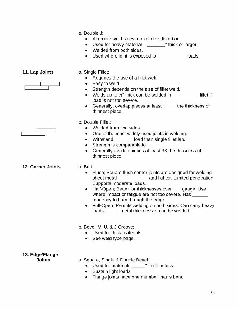
61
e. Double J:
• Alternate weld sides to minimize distortion. • Used for heavy material – _______” thick or larger. • Welded from both sides. • Used where joint is exposed to ___________ loads.
11. Lap Joints a. Single Fillet:
• Requires the use of a fillet weld. • Easy to weld. • Strength depends on the size of fillet weld. • Welds up to ½” thick can be welded in __________ fillet if
load is not too severe. • Generally, overlap pieces at least _____ the thickness of
thinnest piece.
b. Double Fillet: • Welded from two sides. • One of the most widely used joints in welding. • Withstand _______ load than single fillet lap. • Strength is comparable to ______ ______________. • Generally overlap pieces at least 3X the thickness of
thinnest piece. 12. Corner Joints a. Butt:
• Flush; Square flush corner joints are designed for welding sheet metal ___ ________ and lighter. Limited penetration. Supports moderate loads.
• Half-Open; Better for thicknesses over ___ gauge. Use where impact or fatigue are not too severe. Has ______ tendency to burn through the edge.
• Full-Open; Permits welding on both sides. Can carry heavy loads. _____ metal thicknesses can be welded.
b. Bevel, V, U, & J Groove;
• Used for thick materials. • See weld type page.
13. Edge/Flange Joints a. Square, Single & Double Bevel:
• Used for materials _____” thick or less. • Sustain light loads. • Flange joints have one member that is bent.
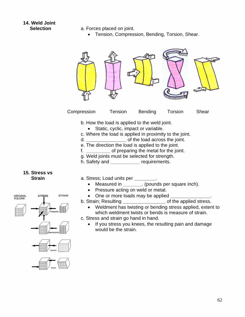
62
14. Weld Joint Selection a. Forces placed on joint.
• Tension, Compression, Bending, Torsion, Shear. Compression Tension Bending Torsion Shear b. How the load is applied to the weld joint.
• Static, cyclic, impact or variable. c. Where the load is applied in proximity to the joint. d. _______________ of the load across the joint. e. The direction the load is applied to the joint. f. _________ of preparing the metal for the joint. g. Weld joints must be selected for strength. h. Safety and ___________ requirements. 15. Stress vs Strain a. Stress; Load units per ________.
• Measured in _______. (pounds per square inch). • Pressure acting on weld or metal. • One or more loads may be applied _______________.
b. Strain; Resulting ________________ of the applied stress. • Weldment has twisting or bending stress applied, extent to
which weldment twists or bends is measure of strain. c. Stress and strain go hand in hand.
• If you stress you knees, the resulting pain and damage would be the strain.