variation of chemical composition of high strength low ... · arc welding, including shielded metal...
TRANSCRIPT
HOSTED BY Available online at www.sciencedirect.com
ScienceDirect
Defence Technology 11 (2015) 147e156www.elsevier.com/locate/dt
Variation of chemical composition of high strength low alloy steels withdifferent groove sizes in multi-pass conventional and pulsed current gas
metal arc weld depositions
K. DEVAKUMARAN a,*, M.R. ANANTHAPADMANABAN b,1, P.K. GHOSH c,2
a Welding Research Institute, Bharat Heavy Electrical Limited, Trichy 620014, Tamil Nadu, Indiab Department of Mechanical Engineering, M.A.M College of Engineering and Technology, Siruganur, Trichy 621 105, Tamil Nadu, India
c Department of Metallurgical & Materials Engineering, Indian Institute of Technology Roorkee, Roorkee 247 667, India
Received 11 September 2014; revised 13 November 2014; accepted 24 November 2014
Available online 20 February 2015
Abstract
25 mm thick micro-alloyed HSLA steel plate is welded by multi-pass GMAW and P-GMAW processes using conventional V-groove andsuitably designed narrow gap with 20 mm (NG-20) and 13 mm (NG-13) groove openings. The variation of weld metal chemistry in the multipass GMA and P-GMA weld depositions are studied by spark emission spectroscopy. It is observed that the narrow groove GMA weld jointshows significant variation of weld metal chemistry compared to the conventional V-groove GMA weld joint since the dilution of base metalextends from the deposit adjacent to groove wall to weld center through dissolution by fusion and solid state diffusion. Further, it is noticed that ahigh rate of metal deposition along with high velocity of droplet transfer in P-GMAW process enhances the dilution of weld deposit andaccordingly varies the chemical composition in multi-pass P-GMAweld deposit. Lower angle of attack to the groove wall surface along with lowheat input in NG-13 weld groove minimizes the effect of dissolution by fusion and solid state diffusion from the deposit adjacent to groove wallto weld center. This results in more uniform properties of NG-13 P-GMA weld in comparison to those of NG-20 and CG welds.Copyright © 2015, China Ordnance Society. Production and hosting by Elsevier B.V. All rights reserved.
Keywords: Pulsed current; Narrow gap; Weld metal chemistry
1. Introduction
The micro-alloyed high strength low alloy (HSLA) steelsare widely used in engineering applications because of theirrelatively low cost, moderate strength and very good tough-ness and fatigue strength, together with their ability to bereadily welded. Arc welding, including shielded metal arcwelding (SMAW), gas metal arc welding (GMAW) and
* Corresponding author. Tel.: þ91 9443689943.
E-mail addresses: [email protected] (K. DEVAKUMARAN),
[email protected] (M.R. ANANTHAPADMANABAN), prakgfmt@
gmail.com, [email protected] (P.K. GHOSH).
Peer review under responsibility of China Ordnance Society.1 Tel.: þ91 9488090838.2 Tel.: þ91 1332 285699.
http://dx.doi.org/10.1016/j.dt.2014.11.001
2214-9147/Copyright © 2015, China Ordnance Society. Production and hosting by
submerged arc welding (SAW), is widely used in fabricationof various components of the HSLA steel. Due to severalmerits of producing comparatively cleaner and continuousweld deposition with automation, the GMAW process isbecoming widely popular, especially for welding of structuralmembers used in power, transportation and defenseindustries.
It is often found that the heterogeneity of weld metalchemical composition, especially for multi-pass welding ofthick sections, gives the different weld joint properties pri-marily due to the repetitive influence of subsequent weldpasses on thermal cycles and the dilution of base metal [1,2].The most significant changes in the properties of weld jointsare due to adverse development of residual stress, micro-structure and corrosion resistance, etc [2]. In case of
Elsevier B.V. All rights reserved.
148 K. DEVAKUMARAN et al. / Defence Technology 11 (2015) 147e156
conventional GMAW process, it is not always possible tomaintain the chemical composition of the weld deposit withina desired level with respect to its influence on thermal andmechanical effects primarily due to limited operating param-eters such as welding current, arc voltage and welding speed,which is used to determine the heat input of the process [3].The pulsed current gas metal arc welding (P-GMAW) processinstead of the conventional GMAW process may be moreuseful due to its ability to precisely control the geometry ofweld deposit dictated by appropriate selection of pulse pa-rameters [4,5] and also operate at low heat input in producinga sound weld joint [6,7]. However, the involvement of largenumber of pulse current parameters in P-GMAW, includingpeak current (Ip), base current (Ib), pulse on-time (Tp), pulseoff-time (Tb) and pulse frequency ( f ), introduces a certaindegree of complexity in controlling the process for desiredwelding. It is reported that the complexity of the processprimarily arising due to the criticality in selection of pulseparameters can be solved by correlating the weld character-istics with a summarized influence of pulse parameters definedby a dimensionless factor ɸ¼(Ib/Ip) � fTb, where Tb isexpressed as [(1/f ) e Tp] [8,9]. Lots of research work has beendone and reported in reference to the P-GMAW arc and metaltransfer dictating thermal behavior and its influence on variouscharacteristics of ferrous and non-ferrous materials weld joints[10e13], but the chemical heterogeneity of multi-pass welddeposit has been not reported.
It is well known that the thermal and mechanical effects ofwelding can be considerably minimized by reducing theamount of weld metal in a joint by using narrow gap (NG)welding technique. Thus, the narrow gap welding procedurecan be considered as an interesting technique to weld thicksection HSLA steel having the improved properties of weldjoint. It is also noticed that the chemistry of weld metal varieswith the change in weld groove size and angle. The chemicalheterogeneity of weld metal in conventional V-groovewelding is comparatively more than that of narrow groovewelding [14]. This is because the latter has relatively lessweld metal deposition in comparison to that of the former. Inaddition, a significant reduction in angle of attack in the caseof narrow groove welding may cause more dilution of basemetal. The increase in area of contact with the arc [14] lowersthe energy density on groove surface at a given energy inputincreases dilution. However, a systematic understanding onsignificant influence of various conventional and pulsedGMAW parameters on the geometry of weld deposit is verynecessary.
Thus, the present work has been carried out to investigatethe effects of GMA and P-GMA welding parameters in thecase of different groove sizes on the variation in the chemicalcomposition of multi-pass weld deposit of 25 mm thick HSLAsteel plate. The changing mechanism of its chemical compo-sition during multi-pass weld deposition in the case ofdifferent groove design and welding parameters were dis-cussed. A systematic understanding of these aspects may bebeneficial in using GMAW process to produce desired weldquality.
2. Experiment
2.1. Welding
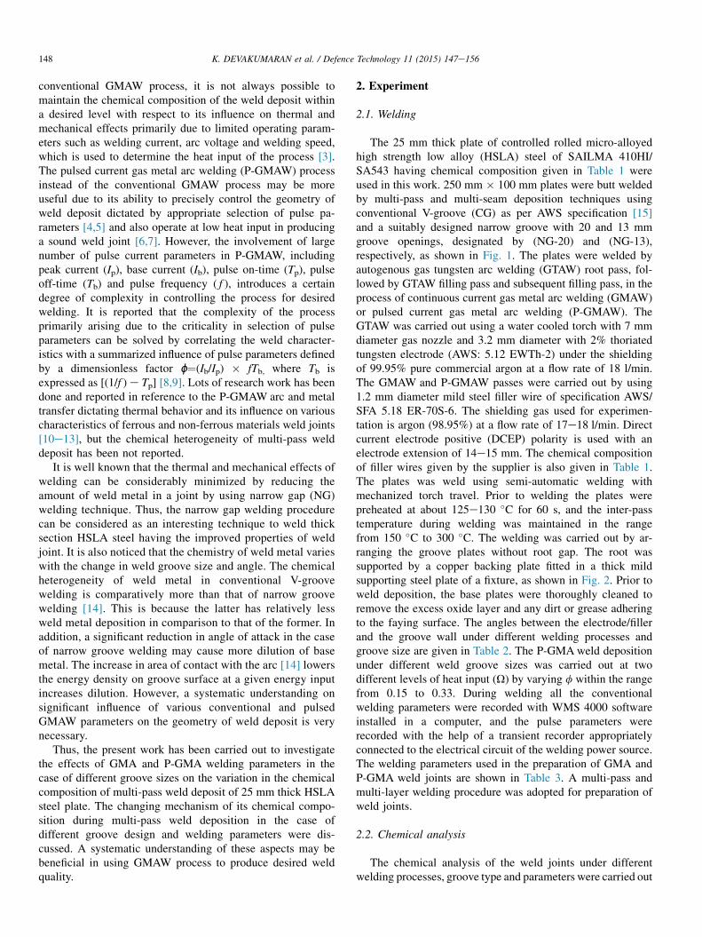
The 25 mm thick plate of controlled rolled micro-alloyedhigh strength low alloy (HSLA) steel of SAILMA 410HI/SA543 having chemical composition given in Table 1 wereused in this work. 250 mm � 100 mm plates were butt weldedby multi-pass and multi-seam deposition techniques usingconventional V-groove (CG) as per AWS specification [15]and a suitably designed narrow groove with 20 and 13 mmgroove openings, designated by (NG-20) and (NG-13),respectively, as shown in Fig. 1. The plates were welded byautogenous gas tungsten arc welding (GTAW) root pass, fol-lowed by GTAW filling pass and subsequent filling pass, in theprocess of continuous current gas metal arc welding (GMAW)or pulsed current gas metal arc welding (P-GMAW). TheGTAW was carried out using a water cooled torch with 7 mmdiameter gas nozzle and 3.2 mm diameter with 2% thoriatedtungsten electrode (AWS: 5.12 EWTh-2) under the shieldingof 99.95% pure commercial argon at a flow rate of 18 l/min.The GMAW and P-GMAW passes were carried out by using1.2 mm diameter mild steel filler wire of specification AWS/SFA 5.18 ER-70S-6. The shielding gas used for experimen-tation is argon (98.95%) at a flow rate of 17e18 l/min. Directcurrent electrode positive (DCEP) polarity is used with anelectrode extension of 14e15 mm. The chemical compositionof filler wires given by the supplier is also given in Table 1.The plates was weld using semi-automatic welding withmechanized torch travel. Prior to welding the plates werepreheated at about 125e130 �C for 60 s, and the inter-passtemperature during welding was maintained in the rangefrom 150 �C to 300 �C. The welding was carried out by ar-ranging the groove plates without root gap. The root wassupported by a copper backing plate fitted in a thick mildsupporting steel plate of a fixture, as shown in Fig. 2. Prior toweld deposition, the base plates were thoroughly cleaned toremove the excess oxide layer and any dirt or grease adheringto the faying surface. The angles between the electrode/fillerand the groove wall under different welding processes andgroove size are given in Table 2. The P-GMAweld depositionunder different weld groove sizes was carried out at twodifferent levels of heat input (U) by varying f within the rangefrom 0.15 to 0.33. During welding all the conventionalwelding parameters were recorded with WMS 4000 softwareinstalled in a computer, and the pulse parameters wererecorded with the help of a transient recorder appropriatelyconnected to the electrical circuit of the welding power source.The welding parameters used in the preparation of GMA andP-GMA weld joints are shown in Table 3. A multi-pass andmulti-layer welding procedure was adopted for preparation ofweld joints.
2.2. Chemical analysis
The chemical analysis of the weld joints under differentwelding processes, groove type and parameters were carried out
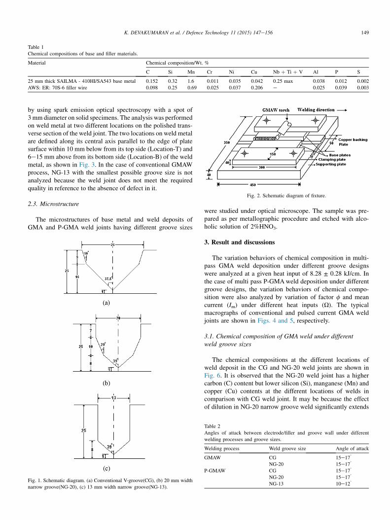
Table 1
Chemical compositions of base and filler materials.
Material Chemical composition/Wt. %
C Si Mn Cr Ni Cu Nb þ Ti þ V Al P S
25 mm thick SAILMA - 410HI/SA543 base metal 0.152 0.32 1.6 0.011 0.035 0.042 0.25 max 0.038 0.012 0.002
AWS: ER: 70S-6 filler wire 0.098 0.25 0.69 0.025 0.037 0.206 e 0.025 0.039 0.003
149K. DEVAKUMARAN et al. / Defence Technology 11 (2015) 147e156
by using spark emission optical spectroscopy with a spot of3 mm diameter on solid specimens. The analysis was performedon weld metal at two different locations on the polished trans-verse section of the weld joint. The two locations on weld metalare defined along its central axis parallel to the edge of platesurface within 10 mm below from its top side (Location-T) and6e15 mm above from its bottom side (Location-B) of the weldmetal, as shown in Fig. 3. In the case of conventional GMAWprocess, NG-13 with the smallest possible groove size is notanalyzed because the weld joint does not meet the requiredquality in reference to the absence of defect in it.
Fig. 2. Schematic diagram of fixture.
2.3. Microstructure
The microstructures of base metal and weld deposits ofGMA and P-GMA weld joints having different groove sizes
Fig. 1. Schematic diagram. (a) Conventional V-groove(CG), (b) 20 mm width
narrow groove(NG-20), (c) 13 mm width narrow groove(NG-13).
were studied under optical microscope. The sample was pre-pared as per metallographic procedure and etched with alco-holic solution of 2%HNO3.
3. Result and discussions
The variation behaviors of chemical composition in multi-pass GMA weld deposition under different groove designswere analyzed at a given heat input of 8.28 ± 0.28 kJ/cm. Inthe case of multi pass P-GMAweld deposition under differentgroove designs, the variation behaviors of chemical compo-sition were also analyzed by variation of factor f and meancurrent (Im) under different heat inputs (U). The typicalmacrographs of conventional and pulsed current GMA weldjoints are shown in Figs. 4 and 5, respectively.
3.1. Chemical composition of GMA weld under differentweld groove sizes
The chemical compositions at the different locations ofweld deposit in the CG and NG-20 weld joints are shown inFig. 6. It is observed that the NG-20 weld joint has a highercarbon (C) content but lower silicon (Si), manganese (Mn) andcopper (Cu) contents at the different locations of welds incomparison with CG weld joint. It may be because the effectof dilution in NG-20 narrow groove weld significantly extends
Table 2
Angles of attack between electrode/filler and groove wall under different
welding processes and groove sizes.
Welding process Weld groove size Angle of attack
GMAW CG 15e17�
NG-20 15e17�
P-GMAW CG 15e17�
NG-20 15e17�
NG-13 10e12�
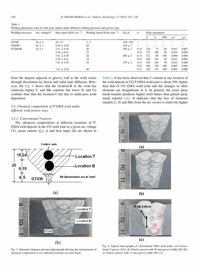
Table 3
Welding parameters used in weld joint studies under different welding processes and groove type.
Welding processes Arc voltage/V Heat input U/(kJ$cm�1) Welding speed S/(cm$min�1) I/Im/A f Pulse parameters
Ip Ib f/Hz tb/s tp/s
GTAW 10 ± 2 16e21 5e7 130e150 e e e e e e
GMAW 24 ± 1 8.28 ± 0.28 28 230 ± 3 e e e e e e
P-GMAW 24 ± 1 7.61 ± 0.38 20 160 ± 2 0.15 324 72 50 0.013 0.007
5.28 ± 0.41 27 0.23 372 108 50 0.016 0.004
7.61 ± 0.38 24 200 ± 3 0.15 372 88 100 0.006 0.004
5.28 ± 0.41 34 0.23 420 128 50 0.015 0.005
7.61 ± 0.38 28 230 ± 2 0.15 420 104 50 0.012 0.008
0.23 440 140 100 0.007 0.003
7.61 ± 0.38 40 0.33 320 176 100 0.004 0.006
150 K. DEVAKUMARAN et al. / Defence Technology 11 (2015) 147e156
from the deposit adjacent to groove wall to the weld centerthrough dissolution by fusion and solid state diffusion. How-ever, the Fig. 6 shows that the location-B of the weld hasrelatively higher C and Mn contents but lower Si and Cucontents than that the location-T has due to multi-pass welddeposition.
3.2. Chemical composition of P-GMA weld underdifferent weld groove sizes
3.2.1. Conventional V-grooveThe chemical compositions at different locations of P-
GMAweld deposit in the CG weld joint at a given arc voltage(V), mean current (Im), f and heat input (U) are shown in
Fig. 3. Schematic diagram and macrophotograph showing the measurement of
chemical composition at two different locations on weld metal.
Table 4. It has been observed that C content at any location ofthe weld deposit in CG P-GMAweld joint is about 30% higherthan that of CG GMA weld joint and the changes in otherelements are insignificant in it. In general, the axial spraymetal transfer produces higher weld fumes than pulsed spraymetal transfer [16]. It indicates that the loss of elements(mainly C, Si and Mn) from the arc cavern is relatively higher
Fig. 4. Typical macrographs of conventional GMA weld joints. (a) Conven-
tional V-groove (CG), (b) Narrow groove with 20 mm groove width (NG-20),
(c) Narrow groove with 13 mm groove width (NG-13).
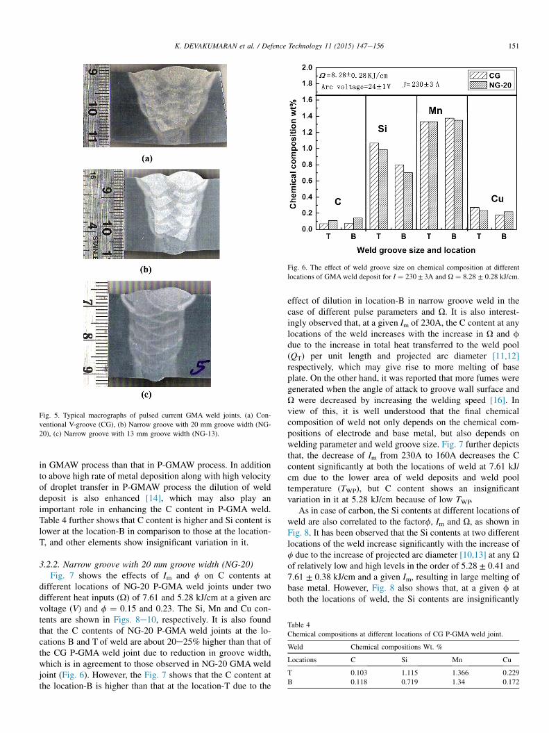
Fig. 5. Typical macrographs of pulsed current GMA weld joints. (a) Con-
ventional V-groove (CG), (b) Narrow groove with 20 mm groove width (NG-
20), (c) Narrow groove with 13 mm groove width (NG-13).
Fig. 6. The effect of weld groove size on chemical composition at different
locations of GMAweld deposit for I ¼ 230± 3A and U ¼ 8.28 ± 0.28 kJ/cm.
Table 4
Chemical compositions at different locations of CG P-GMA weld joint.
Weld Chemical compositions Wt. %
Locations C Si Mn Cu
T 0.103 1.115 1.366 0.229
B 0.118 0.719 1.34 0.172
151K. DEVAKUMARAN et al. / Defence Technology 11 (2015) 147e156
in GMAW process than that in P-GMAW process. In additionto above high rate of metal deposition along with high velocityof droplet transfer in P-GMAW process the dilution of welddeposit is also enhanced [14], which may also play animportant role in enhancing the C content in P-GMA weld.Table 4 further shows that C content is higher and Si content islower at the location-B in comparison to those at the location-T, and other elements show insignificant variation in it.
3.2.2. Narrow groove with 20 mm groove width (NG-20)Fig. 7 shows the effects of Im and f on C contents at
different locations of NG-20 P-GMA weld joints under twodifferent heat inputs (U) of 7.61 and 5.28 kJ/cm at a given arcvoltage (V) and f ¼ 0.15 and 0.23. The Si, Mn and Cu con-tents are shown in Figs. 8e10, respectively. It is also foundthat the C contents of NG-20 P-GMA weld joints at the lo-cations B and T of weld are about 20e25% higher than that ofthe CG P-GMA weld joint due to reduction in groove width,which is in agreement to those observed in NG-20 GMAweldjoint (Fig. 6). However, the Fig. 7 shows that the C content atthe location-B is higher than that at the location-T due to the
effect of dilution in location-B in narrow groove weld in thecase of different pulse parameters and U. It is also interest-ingly observed that, at a given Im of 230A, the C content at anylocations of the weld increases with the increase in U and fdue to the increase in total heat transferred to the weld pool(QT) per unit length and projected arc diameter [11,12]respectively, which may give rise to more melting of baseplate. On the other hand, it was reported that more fumes weregenerated when the angle of attack to groove wall surface andU were decreased by increasing the welding speed [16]. Inview of this, it is well understood that the final chemicalcomposition of weld not only depends on the chemical com-positions of electrode and base metal, but also depends onwelding parameter and weld groove size. Fig. 7 further depictsthat, the decrease of Im from 230A to 160A decreases the Ccontent significantly at both the locations of weld at 7.61 kJ/cm due to the lower area of weld deposits and weld pooltemperature (TWP), but C content shows an insignificantvariation in it at 5.28 kJ/cm because of low TWP.
As in case of carbon, the Si contents at different locations ofweld are also correlated to the factorf, Im and U, as shown inFig. 8. It has been observed that the Si contents at two differentlocations of the weld increase significantly with the increase off due to the increase of projected arc diameter [10,13] at any Uof relatively low and high levels in the order of 5.28 ± 0.41 and7.61 ± 0.38 kJ/cm and a given Im, resulting in large melting ofbase metal. However, Fig. 8 also shows that, at a given f atboth the locations of weld, the Si contents are insignificantly
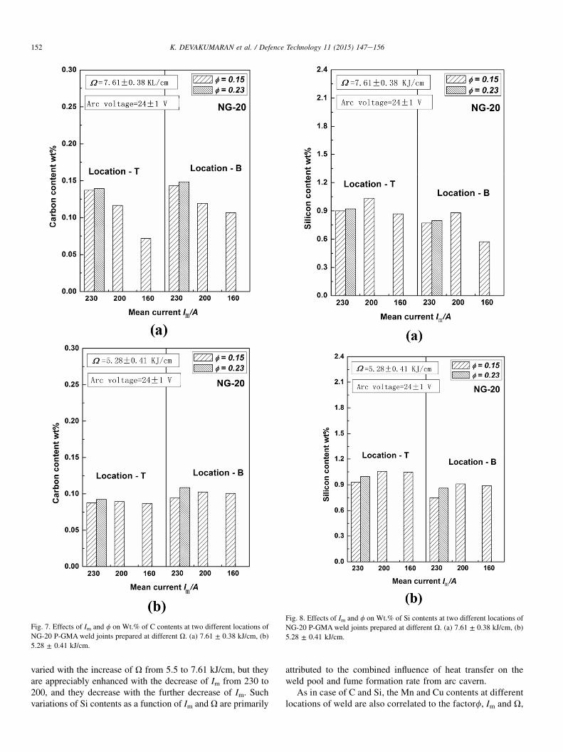
Fig. 7. Effects of Im and f on Wt.% of C contents at two different locations of
NG-20 P-GMAweld joints prepared at different U. (a) 7.61 ± 0.38 kJ/cm, (b)
5.28 ± 0.41 kJ/cm.
Fig. 8. Effects of Im and f on Wt.% of Si contents at two different locations of
NG-20 P-GMAweld joints prepared at different U. (a) 7.61 ± 0.38 kJ/cm, (b)
5.28 ± 0.41 kJ/cm.
152 K. DEVAKUMARAN et al. / Defence Technology 11 (2015) 147e156
varied with the increase of U from 5.5 to 7.61 kJ/cm, but theyare appreciably enhanced with the decrease of Im from 230 to200, and they decrease with the further decrease of Im. Suchvariations of Si contents as a function of Im and U are primarily
attributed to the combined influence of heat transfer on theweld pool and fume formation rate from arc cavern.
As in case of C and Si, the Mn and Cu contents at differentlocations of weld are also correlated to the factorf, Im and U,
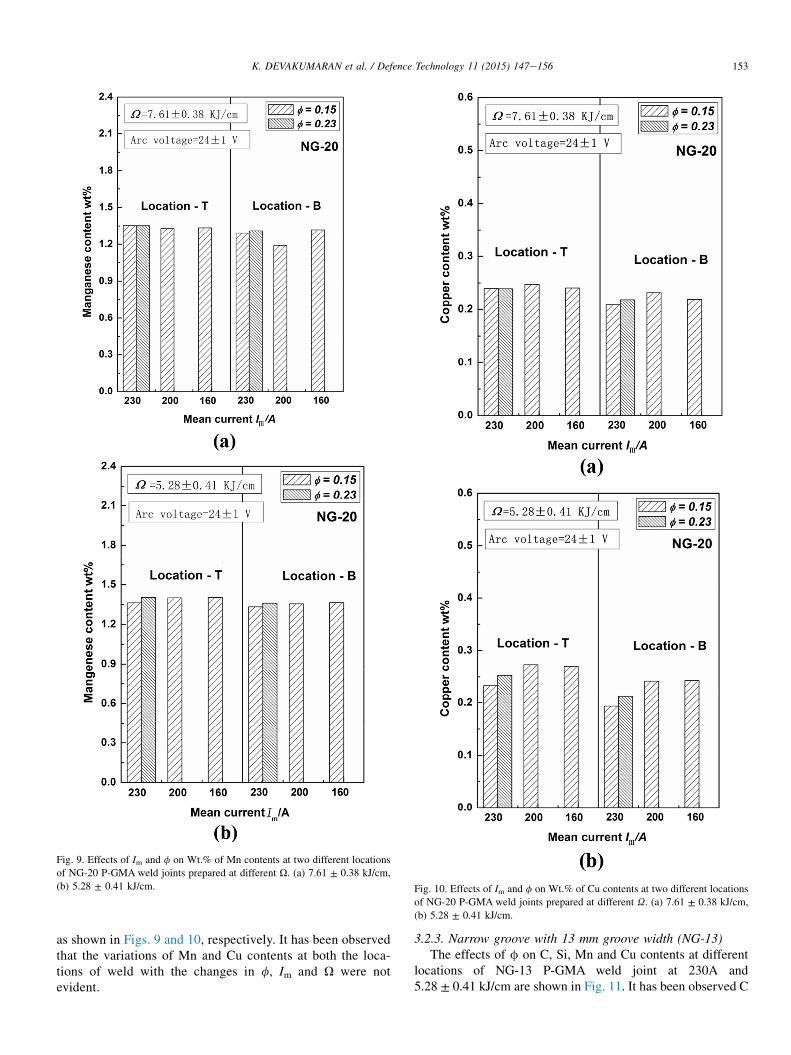
Fig. 9. Effects of Im and f on Wt.% of Mn contents at two different locations
of NG-20 P-GMA weld joints prepared at different U. (a) 7.61 ± 0.38 kJ/cm,
(b) 5.28 ± 0.41 kJ/cm. Fig. 10. Effects of Im and f on Wt.% of Cu contents at two different locations
of NG-20 P-GMA weld joints prepared at different U. (a) 7.61 ± 0.38 kJ/cm,
(b) 5.28 ± 0.41 kJ/cm.
153K. DEVAKUMARAN et al. / Defence Technology 11 (2015) 147e156
as shown in Figs. 9 and 10, respectively. It has been observedthat the variations of Mn and Cu contents at both the loca-tions of weld with the changes in f, Im and U were notevident.
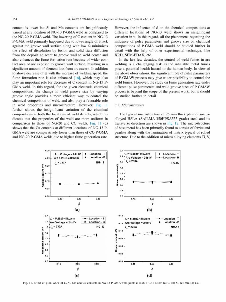
3.2.3. Narrow groove with 13 mm groove width (NG-13)The effects of f on C, Si, Mn and Cu contents at different
locations of NG-13 P-GMA weld joint at 230A and5.28 ± 0.41 kJ/cm are shown in Fig. 11. It has been observed C
154 K. DEVAKUMARAN et al. / Defence Technology 11 (2015) 147e156
content is lower but Si and Mn contents are insignificantlyvaried at any location of NG-13 P-GMA weld as compared tothe NG-20 P-GMAweld. The lowering of C content in NG-13P-GMAweld primarily happened due to lower angle of attackagainst the groove wall surface along with low U minimizesthe effect of dissolution by fusion and solid state diffusionfrom the deposit adjacent to groove wall to weld center andalso enhances the fume formation rate because of wider con-tact area of arc exposed to groove wall surface, resulting in asignificant amount of element loss from arc cavern. In additionto above decrease of U with the increase of welding speed, thefume formation rate is also enhanced [16], which may alsoplay an important role for decrease of C content in NG-13 P-GMA weld. In this regard, for the given electrode chemicalcompositions, the change in weld groove size by varyinggroove angle provides a more efficient way to control thechemical composition of weld, and also play a favorable rolein weld properties and microstructure. However, Fig. 11further shows the insignificant variation of the chemicalcompositions at both the locations of weld depicts, which in-dicates that the properties of the weld are more uniform incomparison to those of NG-20 and CG welds. Fig. 11 (d)shows that the Cu contents at different locations of NG-13 P-GMAweld are comparatively lower than those of CG P-GMAand NG-20 P-GMAwelds due to higher fume generation rate.
Fig. 11. Effect of f on Wt.% of C, Si, Mn and Cu contents in NG-13 P-
However, the influence of f on the chemical compositions atdifferent locations of NG-13 weld shows an insignificantvariation in it. In this regard, all the phenomena regarding theinfluence of pulse parameters and groove size on chemicalcompositions of P-GMA weld should be studied further indetail with the help of other experimental technique, likeXRD, SEM-EDAX, etc.
In the last few decades, the control of weld fumes in arcwelding is a challenging task as the inhalable metal fumespose a potential health hazard to the human body. In view ofthe above observations, the significant role of pulse parametersof P-GMAW process may give wider possibility to control theweld fumes. However, the study on fume generation rate underdifferent pulse parameters and weld groove sizes of P-GMAWprocess is beyond the scope of the present work, but it shouldbe studied further in detail.
3.3. Microstructure
The typical microstructure of 25 mm thick plate of micro-alloyed HSLA (SAILMA-350HI/SA533 grade) steel and itstransverse direction are shown in Fig. 12. The microstructureof base metal has been primarily found to consist of ferrite andpearlite along with the lamination of matrix typical of rolledstructure. Due to the addition of micro alloying elements Ti, V,
GMA weld joints at 5.28 ± 0.41 kJ/cm (a) C, (b) Si, (c) Mn, (d) Cu.
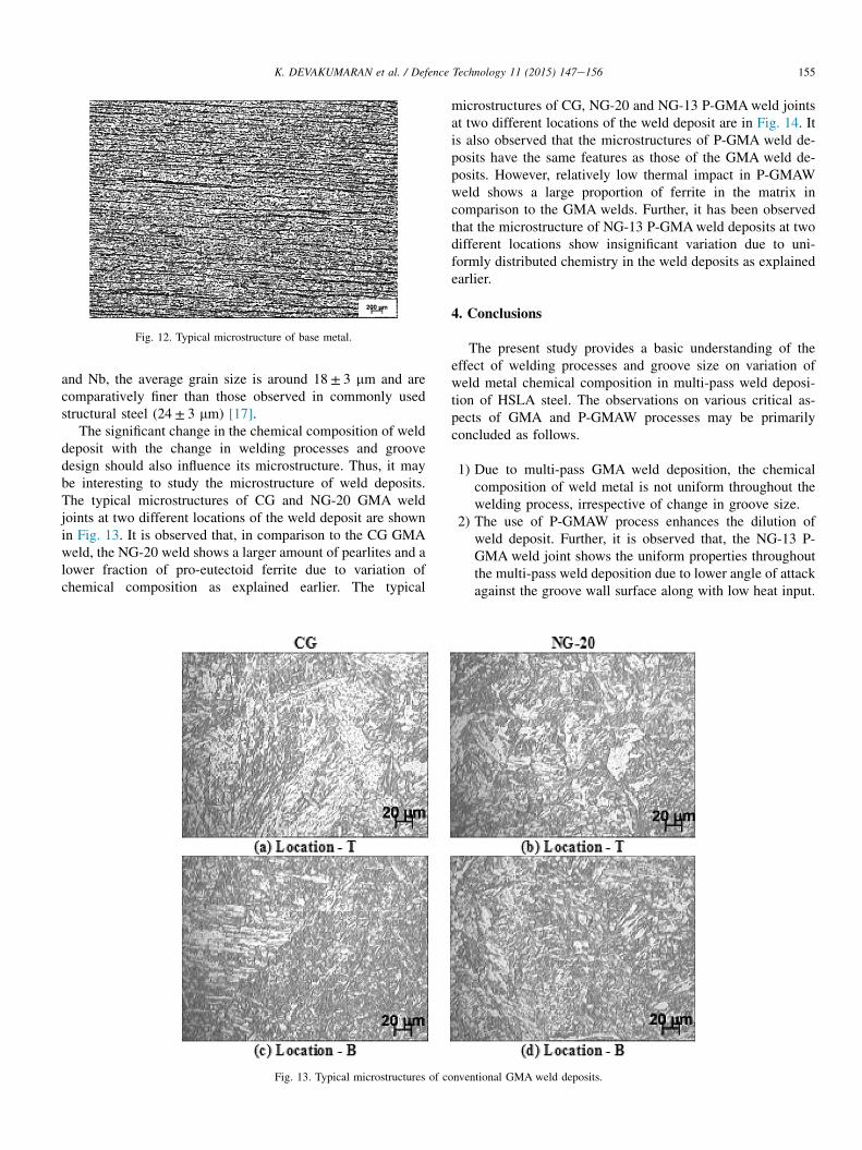
Fig. 12. Typical microstructure of base metal.
155K. DEVAKUMARAN et al. / Defence Technology 11 (2015) 147e156
and Nb, the average grain size is around 18± 3 mm and arecomparatively finer than those observed in commonly usedstructural steel (24 ± 3 mm) [17].
The significant change in the chemical composition of welddeposit with the change in welding processes and groovedesign should also influence its microstructure. Thus, it maybe interesting to study the microstructure of weld deposits.The typical microstructures of CG and NG-20 GMA weldjoints at two different locations of the weld deposit are shownin Fig. 13. It is observed that, in comparison to the CG GMAweld, the NG-20 weld shows a larger amount of pearlites and alower fraction of pro-eutectoid ferrite due to variation ofchemical composition as explained earlier. The typical
Fig. 13. Typical microstructures of co
microstructures of CG, NG-20 and NG-13 P-GMAweld jointsat two different locations of the weld deposit are in Fig. 14. Itis also observed that the microstructures of P-GMA weld de-posits have the same features as those of the GMA weld de-posits. However, relatively low thermal impact in P-GMAWweld shows a large proportion of ferrite in the matrix incomparison to the GMA welds. Further, it has been observedthat the microstructure of NG-13 P-GMAweld deposits at twodifferent locations show insignificant variation due to uni-formly distributed chemistry in the weld deposits as explainedearlier.
4. Conclusions
The present study provides a basic understanding of theeffect of welding processes and groove size on variation ofweld metal chemical composition in multi-pass weld deposi-tion of HSLA steel. The observations on various critical as-pects of GMA and P-GMAW processes may be primarilyconcluded as follows.
1) Due to multi-pass GMA weld deposition, the chemicalcomposition of weld metal is not uniform throughout thewelding process, irrespective of change in groove size.
2) The use of P-GMAW process enhances the dilution ofweld deposit. Further, it is observed that, the NG-13 P-GMA weld joint shows the uniform properties throughoutthe multi-pass weld deposition due to lower angle of attackagainst the groove wall surface along with low heat input.
nventional GMA weld deposits.
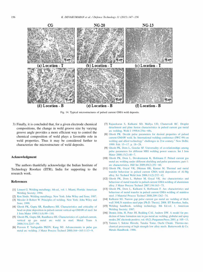
Fig. 14. Typical microstructures of pulsed current GMA weld deposits.
156 K. DEVAKUMARAN et al. / Defence Technology 11 (2015) 147e156
3) Finally, it is concluded that, for a given electrode chemicalcompositions, the change in weld groove size by varyinggroove angle provides a more efficient way to control thechemical composition of weld plays a favorable role inweld properties. Thus it may be considered further tocharacterize the microstructure of weld deposits.
Acknowledgment
The authors thankfully acknowledge the Indian Institute ofTechnology Roorkee (IITR), India for supporting to theresearch work.
References
[1] Linnert G. Welding metallurgy. 4th ed., vol. 1. Miami, Florida: American
Welding Society; 1994.
[2] Kou Sindo. Welding metallurgy. New York: John Wiley and Sons; 1987.
[3] Messler Jr Robert W. Principles of welding. New York: John Wiley and
Sons; 1999.
[4] Ghosh PK, Gupta SR, Randhawa HS. Characteristics and criticality of
bead on plate deposition in pulsed current vertical-up GMAWof steel. Int
J Join Mater 1999;11(4):99e110.[5] Ghosh PK, Gupta SR, Randhawa HS. Characteristics of a pulsed-current,
vertical up gas metal arc weld in steel. Metal Trans A
2000;31A:2247e59.
[6] Praveen P, Yarlagadda PKDV, Kang MJ. Advancements in pulse gas
metal arc welding. J Mater Process Technol 2000;164e165:1113e9.
[7] Rajasekaran S, Kulkarni SD, Mallya UD, Chaturvedi RC. Droplet
detachment and plate fusion characteristics in pulsed current gas metal
arc welding. Weld J 1998;6:254se68s.
[8] Ghosh PK. Decide pulse parameters for desired properties of pulsed
current GMAW weld. In: International welding conference (IWC-99) on
welding and allied technology” challenges in 21st century,” New Delhi;
1999: Feb. 15e17. p. 18e28.
[9] Ghosh PK, Dorn L, Goecke SF. Universality of co-relationships among
pulse parameters for different MIG welding power sources. Int J Join
Mater 2000;13(2):40e7.
[10] Ghosh PK, Dorn L, Devakumaran K, Hofmann F. Pulsed current gas
metal arc welding under different shielding and pulse parameters; part-1:
arc characteristics. ISIJ Int 2009;49(2):251e60.[11] Ghosh PK, Goyal VK, Dhiman HK, Kumar M. Thermal and metal
transfer behaviour in pulsed current GMA weld deposition of Al-Mg
alloy. Sci Technol Weld Join 2006;11(2):232e42.[12] Ghosh PK, Dorn L, Hubner M, Goyal VK. Arc characteristics and
behaviour of metal transfer in pulsed current GMAwelding of aluminium
alloy. J Mater Process Technol 2007;194:163e75.
[13] Ghosh PK, Dorn L, Kulkarni S, Hoffmann F. Arc characteristics and
behaviour of metal transfer in pulsed current GMA welding of stainless
steel. J Material Process Technol 2008;209:1262e74.
[14] Kulkarni SG. Narrow gap pulse current gas metal arc welding of thick
wall 304LN stainless steel pipe [Ph.D. Thesis]. 2008. IIT Roorkee, India.
[15] Welding handbook, welding technology. 8th Ed.vol. 1. American
Welding Society; 1987.
[16] Dennis John, H, Peter JH, Redding CAJ, Andrew DW. A model for pre-
diction of fume formation rate in gas metal arc welding, globular and spray
modes, DC electrode positive, vol. 45(2). Pergamon Press; 2001. p. 105e13.
[17] Tamura I, Sekine Hiroshi, Tanaka Tomo, Ouchi Chiaki. Thermo-me-
chanical processing of high strength low alloy steels. Butterworth & Co.
Metals Handbook; 1988.