waves - ecole globale international girls' school waves 1 waves 1 the diagram ... 8 you are...
TRANSCRIPT

A2 WAVES
1
Waves
1 The diagram represents a segment of a string along which a transverse wave is travelling.
(i) What is the amplitude of the wave?
_________________________________________________________________________________ [1]
(ii) What is the wavelength of the wave?
_________________________________________________________________________________ [1]
(iii) how many cycles are shown in the diagram?
_________________________________________________________________________________ [1]
2 The diagram shows a segment of a transverse wave drawn full scale. The frequency of this wave is 2Hz.
Measure its amplitude and wavelength
____________________________________________________________________________________
____________________________________________________________________________________
_________________________________________________________________________________ [2]

A2 WAVES
2
3 The diagrams below show a stretched slinky spring drawn to a scale 1 cm = 5 cm. Diagram A showsa section of the slinky before a wave reaches it. Diagram B shows the slinky at an instant as a wavetravels through it.
(a) What kind of wave is travelling through the slinky?
_________________________________________________________________________________ [1]
(b) On diagram B mark two successive compressions and two successive rarefactions. [1]
(c) Use a ruler and the scale of the diagram to determine the wavelength of this wave.
_________________________________________________________________________________ [1]
(d) Find and mark a coil in diagram B that has moved furthest from its equilibrium position in diagram A,and hence determine the amplitude of the wave.
____________________________________________________________________________________
_________________________________________________________________________________ [2]
A
B
scale 1 cm = 5 cm

A2 WAVES
3
4 The speed, c, of a transverse wave along a string or wire under tension is given by c T= µ ,
where T is the Tension in Newtons and µ is the mass per unit length in kg/m.
(a) Show that this equation is homogeneous.
____________________________________________________________________________________
____________________________________________________________________________________
_________________________________________________________________________________ [2]
(b) The diagram shows a wire of length 2 metres kept in tension by hanging a weight from one end. Themass per unit length for this wire is 5 g/m. If the weight that keeps the wire in tension is 0.5Newtons. A vibrator is used to produce standing waves in the wire.
(i) calculate the speed of the transverse wave travelling along the wire when it is oscillating.
____________________________________________________________________________________
____________________________________________________________________________________
_________________________________________________________________________________ [2]
(ii) Does the speed of the wave depend on the frequency at which the vibrator oscillates the wire?Explain your answer.
____________________________________________________________________________________
____________________________________________________________________________________
_________________________________________________________________________________ [2]
(iii) Calculate the wavelength of the fundamental.
____________________________________________________________________________________
_________________________________________________________________________________ [2]
(iv) What is the lowest frequency for standing waves in this set up?
____________________________________________________________________________________
____________________________________________________________________________________
_________________________________________________________________________________ [2]

A2 WAVES
4
(c) Draw diagrams to show the first four harmonics for standing waves. In each case calculate thewavelength and frequency of the standing wave. Show all working.

A2 WAVES
5
5 The diagrams on the right showsnapshots of successive positions of asegment of a string at intervals of 1/8th
of the period of the wave.
(a) Mark the nodes on one of the diagrams,and explain why these points are nodes.
____________________________________
____________________________________
____________________________________
(b) Mark the positions of the antinodes, andexplain why these points are antinodes.
(c) Use the scale on the diagrams todetermine the amplitude andwavelength of the standing wave.
____________________________________
____________________________________
____________________________________
(d) How many cycles are displayed in thesediagrams?
____________________________________
(e) If the time interval between successive diagrams is 0.1 seconds, calculate the frequency of thestanding wave, and hence its speed.
____________________________________________________________________________________
____________________________________________________________________________________
____________________________________________________________________________________
____________________________________________________________________________________
_________________________________________________________________________________ [3]

A2 WAVES
6
6 The diagram shows a pulse, P, travelling up a heavy rope. The rope isfirmly attached to a ceiling at A. Given that the speed of a transverse
wave through a string is given by c T= µ , will the speed of the pulse
change as it moves up the rope, and if so does the speed increase ordecrease. Explain your answer as fully as you can.
____________________________________________________________________________________
____________________________________________________________________________________
____________________________________________________________________________________
____________________________________________________________________________________
_________________________________________________________________________________ [2]

AS Circuits
1
Circuits
Name & Set
1 The battery in the circuit below has an e.m.f. of 5.4 V and drives a current of 0.30 A through thelamp.
(a) On the circuit above, label the voltmeter V and the ammeter A. [1]
(b) The voltmeter reading is 4.8 V. Explain why the voltmeter reading is less than the e.m.f. of thebattery.
____________________________________________________________________________________
____________________________________________________________________________________
_________________________________________________________________________________ [2]
(c) Calculate the internal resistance of the battery.
____________________________________________________________________________________
____________________________________________________________________________________
________________________________________________________________________________ [3]
(d) Calculate the energy transformed per second in the lamp.
____________________________________________________________________________________
____________________________________________________________________________________
________________________________________________________________________________ [3]
(e) State two assumptions you made in order to complete these calculations.
(i) _________________________________________________________________________________
____________________________________________________________________________________
________________________________________________________________________________ [2]
(ii) _________________________________________________________________________________
____________________________________________________________________________________
________________________________________________________________________________ [2]
5.4 VLamp
0.30 A

AS Circuits
2
2 (a) Define electrical resistance.
____________________________________________________________________________________
________________________________________________________________________________ [1]
(b) The two graphs below represent current-voltage characteristics for a metal conductor and athermistor.
(i) The resistance of the metal conductor is 833 Ω. Use this value to find appropriate values to label thecurrent axis on the graph.
____________________________________________________________________________________
____________________________________________________________________________________
____________________________________________________________________________________
________________________________________________________________________________ [3]
(ii) Calculate the change in resistance of the thermistor between the points A and B marked on thegraph.
____________________________________________________________________________________
____________________________________________________________________________________
________________________________________________________________________________ [3]
(iii) What do the graphs tell you about the difference in behaviour between the metal and thethermistor?
____________________________________________________________________________________
____________________________________________________________________________________
____________________________________________________________________________________
________________________________________________________________________________ [2]
-5 +5
I/A
V/V
I/mA
60
40
20
00 1 2 3
V/V
x
x
A
B
Metallic conductor
Thermistor
AS Circuits
3
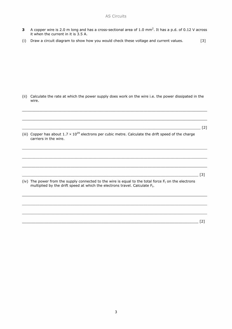
3 A copper wire is 2.0 m long and has a cross-sectional area of 1.0 mm2. It has a p.d. of 0.12 V acrossit when the current in it is 3.5 A.
(i) Draw a circuit diagram to show how you would check these voltage and current values. [3]
(ii) Calculate the rate at which the power supply does work on the wire i.e. the power dissipated in thewire.
____________________________________________________________________________________
____________________________________________________________________________________
_________________________________________________________________________________ [2]
(iii) Copper has about 1.7 × 1029 electrons per cubic metre. Calculate the drift speed of the chargecarriers in the wire.
____________________________________________________________________________________
____________________________________________________________________________________
____________________________________________________________________________________
________________________________________________________________________________ [3]
(iv) The power from the supply connected to the wire is equal to the total force Ft on the electronsmultiplied by the drift speed at which the electrons travel. Calculate Ft.
____________________________________________________________________________________
____________________________________________________________________________________
____________________________________________________________________________________
________________________________________________________________________________ [2]
AS Circuits
4
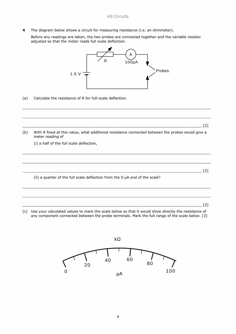
4 The diagram below shows a circuit for measuring resistance (i.e. an ohmmeter).
Before any readings are taken, the two probes are connected together and the variable resistoradjusted so that the meter reads full scale deflection.
(a) Calculate the resistance of R for full-scale deflection.
____________________________________________________________________________________
____________________________________________________________________________________
________________________________________________________________________________ [2]
(b) With R fixed at this value, what additional resistance connected between the probes would give ameter reading of
(i) a half of the full scale deflection,
____________________________________________________________________________________
____________________________________________________________________________________
________________________________________________________________________________ [2]
(ii) a quarter of the full scale deflection from the 0 µA end of the scale?
____________________________________________________________________________________
____________________________________________________________________________________
________________________________________________________________________________ [2]
(c) Use your calculated values to mark the scale below so that it would show directly the resistance ofany component connected between the probe terminals. Mark the full range of the scale below. [3]
Probes1.5 V
R 100µA
A
020
40 6080
100µA
kΩ

AS Circuits
5
5 A semiconducting strip, 6 mm wide and 0.5 mm thick, carries a current of 8mA. The carrier densityis 7 × 10²³ m-3. Calculate the carrier drift speed.
____________________________________________________________________________________
____________________________________________________________________________________
________________________________________________________________________________ [3]
An approximate value for the drift speed in a copper wire of the same dimensions and carrying the samecurrent would be about 10-7 ms-l. Compare this figure with your calculated result and account for anydifference in terms of the equation I = nAqv.
____________________________________________________________________________________
____________________________________________________________________________________
________________________________________________________________________________ [3]
Explain why the resistance of a semiconducting strip decreases when its temperature rises.
____________________________________________________________________________________
____________________________________________________________________________________
____________________________________________________________________________________
____________________________________________________________________________________
________________________________________________________________________________ [2]
6 A torch has three identical cells, each of e.m.f. 1.5 V, and a lamp that is labelled 3.5 V, 0.3 A.(i) Draw a circuit diagram for the torch. [2]
(ii) Assume that the lamp is lit to normal brightness and that the connections have negligibleresistance. Mark on your diagram the voltage across each circuit component and the currentflowing in the lamp. [3]
(iii) Calculate the internal resistance of one of these cells.
____________________________________________________________________________________
____________________________________________________________________________________
____________________________________________________________________________________
_________________________________________________________________________________ [3]

AS Circuits
6
7 A cell of negligible internal resistance is connected in series with a microammeter of negligibleresistance and two resistors of 10 kΩ and 15 kΩ. The current is 200 µA.
(a) (i) Draw a circuit diagram of the arrangement. [1]
(ii) Calculate the e.m.f. of the cell.
____________________________________________________________________________________
____________________________________________________________________________________
_________________________________________________________________________________ [2]
(b) (i) When a voltmeter is connected in parallel with the 15 kΩ resistor, the current in themicroammeter increases to 250 µA. Sketch a diagram of the modified circuit. [1]
(ii) Calculate the resistance of the voltmeter.
____________________________________________________________________________________
____________________________________________________________________________________
_________________________________________________________________________________ [3]

AS Circuits
7
8 You are given a piece of resistance wire. It is between two and three metres long and has aresistance of about 15 Ω. You are asked to measure the resistivity of the metal alloy it is madefrom.
Make the necessary additions to the following circuit to enable it to be used for the experiment. [2]Describe briefly how you would use the circuit above to measure the resistance of the wire.
____________________________________________________________________________________
____________________________________________________________________________________
____________________________________________________________________________________
____________________________________________________________________________________
____________________________________________________________________________________
____________________________________________________________________________________
_________________________________________________________________________________ [5]
Once the resistance of the wire is known, two more quantities must be measured before its resistivity canbe calculated. What are they?
____________________________________________________________________________________
____________________________________________________________________________________
____________________________________________________________________________________
_________________________________________________________________________________ [2]
Is there any advantage in finding the resistance of the wire from a graph compared with calculating anaverage value from the measurements? Explain your answer.
____________________________________________________________________________________
____________________________________________________________________________________
____________________________________________________________________________________
_________________________________________________________________________________ [2]
5
2 V
R1
Resistan
ce wire

AS Circuits
8
9 The circuit diagram shows a 12 V power supply connected across a potential divider R by the slidingcontact P. The potential divider is linked to a resistance wire XY through an ammeter. A voltmeter isconnected across the wire XY.
(a) Explain, with reference to this circuit, the term potential divider.
____________________________________________________________________________________
____________________________________________________________________________________
____________________________________________________________________________________
_________________________________________________________________________________ [2]
(b) The circuit has been set up to measure the resistance of the wire XY. A set of voltage and currentmeasurements is recorded and used to draw the following graph.
(i) Explain why the curve deviates from a straight line at higher current values.
____________________________________________________________________________________
____________________________________________________________________________________
____________________________________________________________________________________
_________________________________________________________________________________ [2]
12 VWire
R
P X
Y
A
V
6
5
4
3
2
1
00 0.2 0.4 0.6 0.8 1.0
p.d. /V
I /A

AS Circuits
9
9 cont. (ii) Calculate the resistance of the wire for low current values.
____________________________________________________________________________________
____________________________________________________________________________________
____________________________________________________________________________________
_________________________________________________________________________________ [2]
(c) To determine the resistivity of the material of the wire, two more quantities would have to bemeasured. What are they?
Explain which of these two measurements you would expect to have the greater influence on theerror in a calculated value for the resistivity? How would you minimise this error?
____________________________________________________________________________________
____________________________________________________________________________________
____________________________________________________________________________________
_________________________________________________________________________________ [3]
10 (i) Define the term resistivity.
____________________________________________________________________________________
_________________________________________________________________________________ [2]
(ii) The resistivity of copper is 1.7 × 10⁻⁸ Ωm. A copper wire is 0.6 m long and has a cross-sectional areaof 1 mm2. Calculate its resistance.
____________________________________________________________________________________
____________________________________________________________________________________
____________________________________________________________________________________
_________________________________________________________________________________ [3]
Two such wires are used to connect a lamp to a power supply of negligible internal resistance. Thepotential difference across the lamp is 12 V and its power is 36 W.
(iii) Calculate the potential difference across each wire.
____________________________________________________________________________________
____________________________________________________________________________________
____________________________________________________________________________________
_________________________________________________________________________________ [3]
(iv) Draw a circuit diagram of the above arrangement. Label the potential differences across the wires,lamp and power supply. [3]
AS Circuits
10
11 (a) Define the term resistivity.
____________________________________________________________________________________
____________________________________________________________________________________
____________________________________________________________________________________
_________________________________________________________________________________ [2]
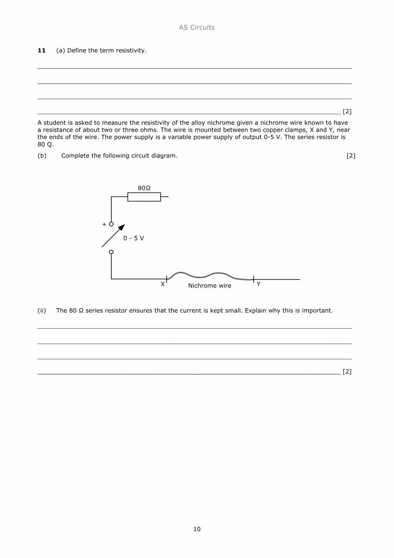
A student is asked to measure the resistivity of the alloy nichrome given a nichrome wire known to havea resistance of about two or three ohms. The wire is mounted between two copper clamps, X and Y, nearthe ends of the wire. The power supply is a variable power supply of output 0-5 V. The series resistor is80 Q.
(b) Complete the following circuit diagram. [2]
(ii) The 80 Ω series resistor ensures that the current is kept small. Explain why this is important.
____________________________________________________________________________________
____________________________________________________________________________________
____________________________________________________________________________________
_________________________________________________________________________________ [2]
80
0 - 5 V
Nichrome wireX Y
+
AS Circuits
11
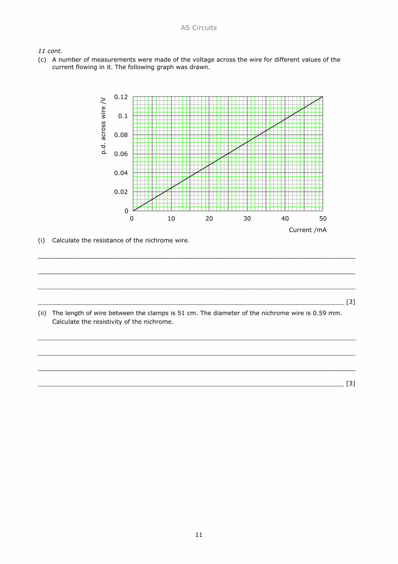
11 cont.(c) A number of measurements were made of the voltage across the wire for different values of the
current flowing in it. The following graph was drawn.
(i) Calculate the resistance of the nichrome wire.
____________________________________________________________________________________
____________________________________________________________________________________
____________________________________________________________________________________
_________________________________________________________________________________ [3]
(ii) The length of wire between the clamps is 51 cm. The diameter of the nichrome wire is 0.59 mm.Calculate the resistivity of the nichrome.
____________________________________________________________________________________
____________________________________________________________________________________
____________________________________________________________________________________
_________________________________________________________________________________ [3]
0.12
0.1
0.08
0.06
0.04
0.02
00 10 20 30 40 50
p.d
. ac
ross
wire
/V
Current /mA
AS Circuits
12
12 (a) Describe how you would determine by experiment approximate values for the e.m.f. and theinternal resistance of a torch battery. Include a circuit diagram.
____________________________________________________________________________________
____________________________________________________________________________________
____________________________________________________________________________________
____________________________________________________________________________________
____________________________________________________________________________________
____________________________________________________________________________________
____________________________________________________________________________________
____________________________________________________________________________________
____________________________________________________________________________________
____________________________________________________________________________________
____________________________________________________________________________________
____________________________________________________________________________________
____________________________________________________________________________________
____________________________________________________________________________________
____________________________________________________________________________________
_________________________________________________________________________________ [4]
AS Circuits
13
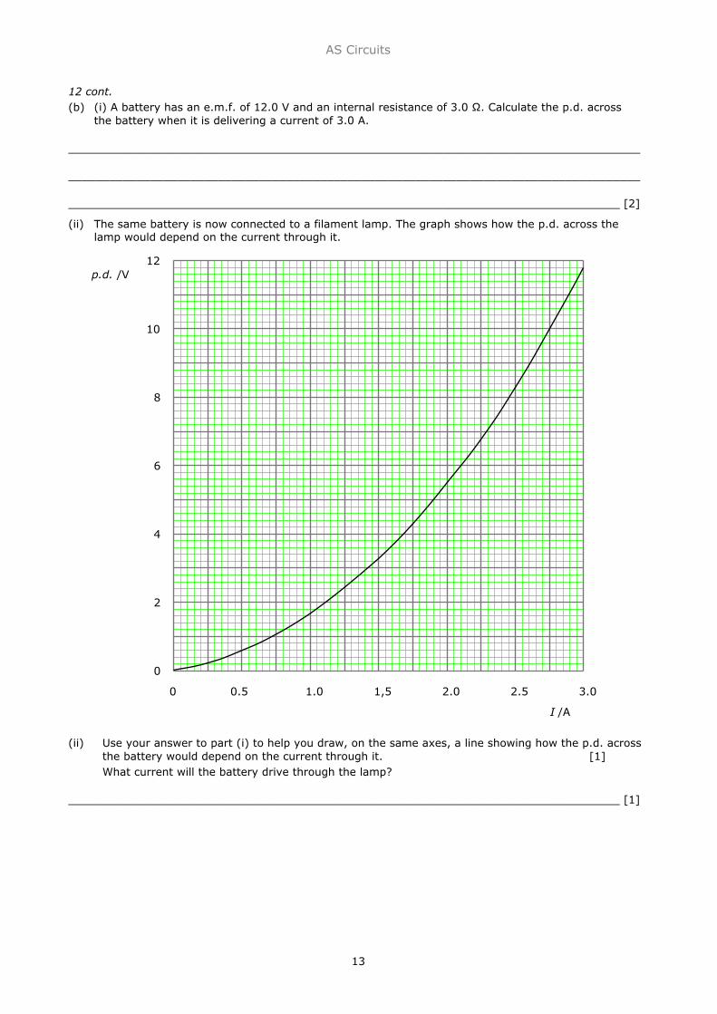
12 cont.(b) (i) A battery has an e.m.f. of 12.0 V and an internal resistance of 3.0 Ω. Calculate the p.d. across
the battery when it is delivering a current of 3.0 A.
____________________________________________________________________________________
____________________________________________________________________________________
_________________________________________________________________________________ [2]
(ii) The same battery is now connected to a filament lamp. The graph shows how the p.d. across thelamp would depend on the current through it.
(ii) Use your answer to part (i) to help you draw, on the same axes, a line showing how the p.d. acrossthe battery would depend on the current through it. [1]What current will the battery drive through the lamp?
_________________________________________________________________________________ [1]
12
10
8
6
4
2
0
p.d. /V
0 0.5 1.0 1,5 2.0 2.5 3.0
I /A

AS Circuits
14
13 The circuit shows a battery of negligible internal resistance connected to three resistors.
(i) Calculate the p.d. across the 4Ω resistor.
____________________________________________________________________________________
____________________________________________________________________________________
_________________________________________________________________________________ [2]
(ii) Calculate current I1.
____________________________________________________________________________________
____________________________________________________________________________________
____________________________________________________________________________________
_________________________________________________________________________________ [3]
(iii) Calculate resistance R.
____________________________________________________________________________________
____________________________________________________________________________________
____________________________________________________________________________________
_________________________________________________________________________________ [2]
9.0 V
4
24 R
0.75 A
I1I2
AS Circuits
15
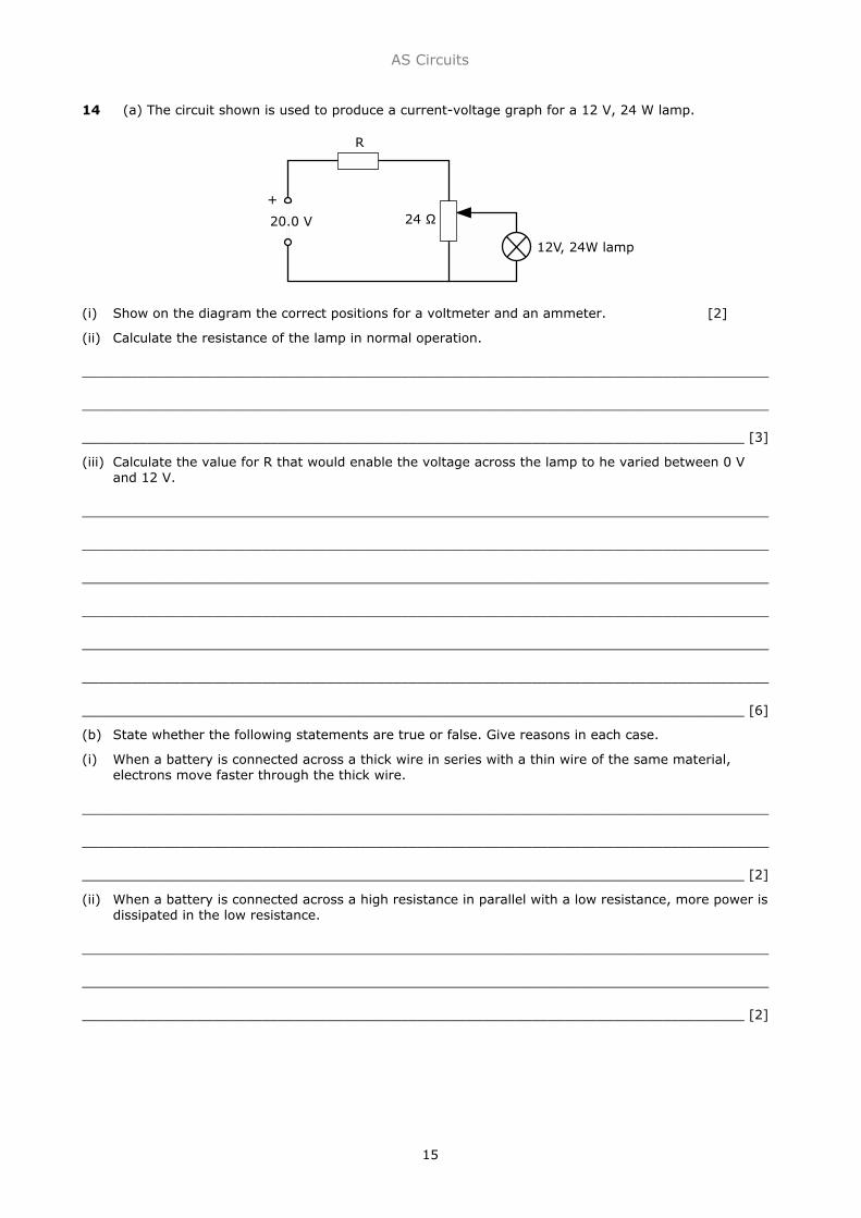
14 (a) The circuit shown is used to produce a current-voltage graph for a 12 V, 24 W lamp.
(i) Show on the diagram the correct positions for a voltmeter and an ammeter. [2]
(ii) Calculate the resistance of the lamp in normal operation.
____________________________________________________________________________________
____________________________________________________________________________________
_________________________________________________________________________________ [3]
(iii) Calculate the value for R that would enable the voltage across the lamp to he varied between 0 Vand 12 V.
____________________________________________________________________________________
____________________________________________________________________________________
____________________________________________________________________________________
____________________________________________________________________________________
____________________________________________________________________________________
____________________________________________________________________________________
_________________________________________________________________________________ [6]
(b) State whether the following statements are true or false. Give reasons in each case.
(i) When a battery is connected across a thick wire in series with a thin wire of the same material,electrons move faster through the thick wire.
____________________________________________________________________________________
____________________________________________________________________________________
_________________________________________________________________________________ [2]
(ii) When a battery is connected across a high resistance in parallel with a low resistance, more power isdissipated in the low resistance.
____________________________________________________________________________________
____________________________________________________________________________________
_________________________________________________________________________________ [2]
20.0 V 24
R
+
12V, 24W lamp
AS Circuits
16
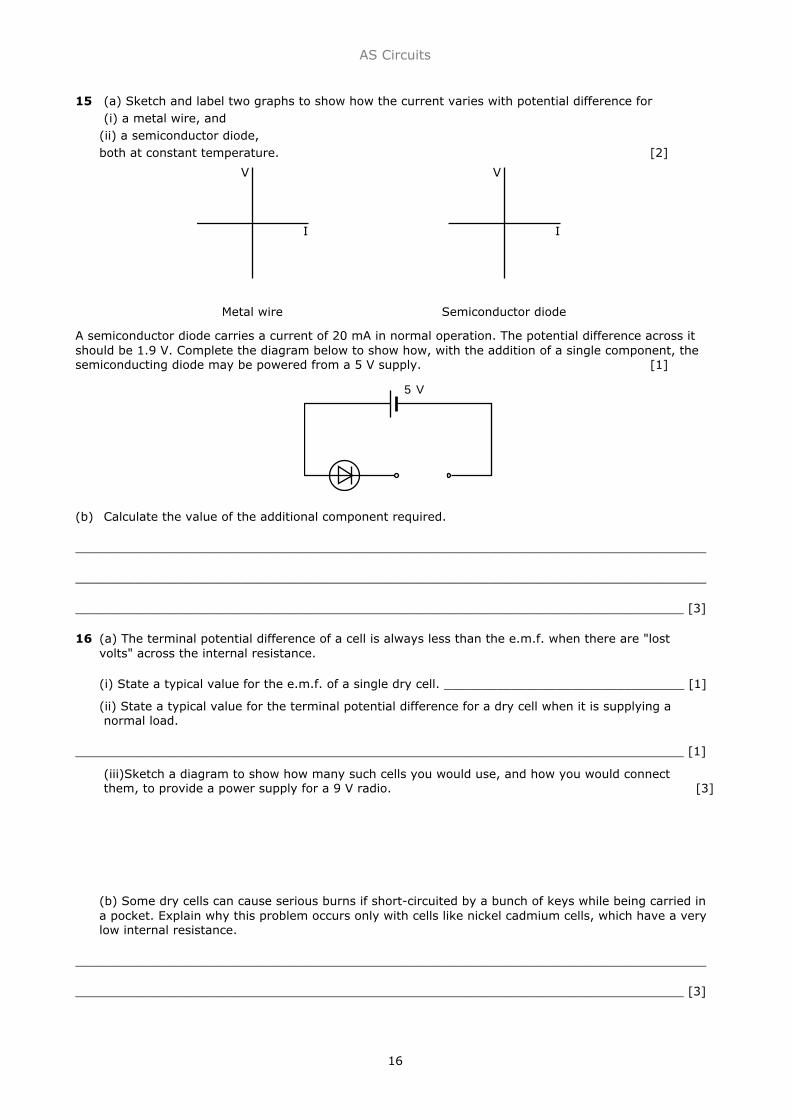
15 (a) Sketch and label two graphs to show how the current varies with potential difference for(i) a metal wire, and
(ii) a semiconductor diode,both at constant temperature. [2]
A semiconductor diode carries a current of 20 mA in normal operation. The potential difference across itshould be 1.9 V. Complete the diagram below to show how, with the addition of a single component, thesemiconducting diode may be powered from a 5 V supply. [1]
(b) Calculate the value of the additional component required.
____________________________________________________________________________________
____________________________________________________________________________________
_________________________________________________________________________________ [3]
16 (a) The terminal potential difference of a cell is always less than the e.m.f. when there are "lostvolts" across the internal resistance.
(i) State a typical value for the e.m.f. of a single dry cell. ________________________________ [1]
(ii) State a typical value for the terminal potential difference for a dry cell when it is supplying anormal load.
_________________________________________________________________________________ [1]
(iii)Sketch a diagram to show how many such cells you would use, and how you would connectthem, to provide a power supply for a 9 V radio. [3]
(b) Some dry cells can cause serious burns if short-circuited by a bunch of keys while being carried ina pocket. Explain why this problem occurs only with cells like nickel cadmium cells, which have a verylow internal resistance.
____________________________________________________________________________________
_________________________________________________________________________________ [3]
5 V
V
I
Metal wire
V
I
Semiconductor diode

AS Circuits
17
17 The power supplies in the two circuits shown below are identical.
(i) Write down the relationship between I1, I2 and I that must hold if the combined resistance of theparallel pair, Rl and R2, is to equal RT.
____________________________________________________________________________________
____________________________________________________________________________________
_________________________________________________________________________________ [1]
(ii) Hence derive the formula for the equivalent resistance of two resistors connected in parallel.
____________________________________________________________________________________
____________________________________________________________________________________
_________________________________________________________________________________ [3]
(iii) Use your formula to show that the resistance between the terminals of a low-resistance componentis hardly changed when a high-resistance voltmeter is connected in parallel with it.
____________________________________________________________________________________
____________________________________________________________________________________
_________________________________________________________________________________ [2]
R1 R2V
I1 I2
+
-RV
I
+
-

AS Circuits
18
18 The graph shows how the resistance R of a thermistor depends on temperature.
(a) In terms of the behaviour of the material of the thermistor, explain qualitatively the variation shownon the graph.
____________________________________________________________________________________
____________________________________________________________________________________
____________________________________________________________________________________
_________________________________________________________________________________ [2]
A student connects the thermistor in series with a 330 Ω resistor and applies a potential difference of 2.0
V. A high resistance voltmeter connected in parallel with the resistor reads 0.80 V.
(b) (i) Calculate the resistance of the thermistor.
____________________________________________________________________________________
____________________________________________________________________________________
____________________________________________________________________________________
_________________________________________________________________________________ [3]
(ii) The student now increases the applied p.d. from 2.0 V to 20 V. She expects the voltmeter reading toincrease from 0.80 V to 8.0 V but is surprised to find that it is greater. Explain this.
____________________________________________________________________________________
____________________________________________________________________________________
____________________________________________________________________________________
_________________________________________________________________________________ [3]
V
330
2.0 V
Res
ista
nce
Temperature

AS Circuits
19
19 The resistors R1 and R2 in circuit (fig. 1) are equivalent to a single resistor R in circuit (fig. 2).
(a) Prove that R = R1 + R2.
____________________________________________________________________________________
____________________________________________________________________________________
____________________________________________________________________________________
____________________________________________________________________________________
_________________________________________________________________________________ [3](b) (i) In a real circuit it is usually assumed that there is no potential difference between two points,
such as P and Q in figure 1, which are on the same connecting lead. Explain why this is usually agood approximation.
____________________________________________________________________________________
____________________________________________________________________________________
____________________________________________________________________________________
_________________________________________________________________________________ [2](ii) In what circumstances might the approximation break down?
____________________________________________________________________________________
_________________________________________________________________________________ [1](c) A laboratory lead consists of 16 strands of fine copper wire twisted together. Each strand is 30 cm
long with a diameter of 0.15 mm. Calculate the potential difference across the lead when it iscarrying a current of 2.0 A.
(The resistivity of copper = 1.7 x 10⁻⁸ Ωm.)
____________________________________________________________________________________
____________________________________________________________________________________
____________________________________________________________________________________
____________________________________________________________________________________
_________________________________________________________________________________ [4]
R1 R2
P
Q
fig. 1
R
fig. 2

AS Circuits
20
20 The diagram shows the circuit of a fluorescent light fitting. It consists of a tube, a starter and aballast resistance of 300 Ω.
The fluorescent tube is filled with gas. It contains two filaments at A and B of resistance 50 Ω thatheat the gas.
When the light is first turned on, the tube does not conduct but the starter does, drawing a current of0.50 A from the 230 V supply.
(a) (i) Calculate the voltages across the ballast resistor and each filament when the current flows
____________________________________________________________________________________
____________________________________________________________________________________
____________________________________________________________________________________
_________________________________________________________________________________ [4]
(ii) Mark these voltages on the diagram, and hence calculate the voltage across the starter when thestarting current is flowing. Mark your answer on the diagram.
[2]
(b) The starting current heats the filaments and the gas in the tube but the voltage across the tube isnot large enough to make it conduct. However, after a few seconds the starter stops conducting. Thevoltage across the tube rises and the gas conducts. A current now flows from A to B and the tubelights up.
(i) What fundamental change is necessary for a gas, which was an insulator, to be able to conduct?
____________________________________________________________________________________
_________________________________________________________________________________ [1]
(ii) Now that the tube is conducting, the voltage across AB is 110 V. Calculate the power dissipated inthe whole circuit.
____________________________________________________________________________________
_________________________________________________________________________________ [3]
(iii) In a faulty fluorescent lamp the filaments at both ends of the tube glow steadily but the tube doesnot light up. Identify, with a reason, the faulty component.
____________________________________________________________________________________
_________________________________________________________________________________ [1]
Starter
Ballast 300
Tube
I
50 50
Vstarter
230 V
AB

1
Current characteristics 1
Name & Set
In an experiment with a filament lamp, the following readings of p.d. and current were obtained.
p.d./ V 0 1.0 2.0 3.0 4.0 5.0 6.0
Current/ A 0 0.1 0.19 0.27 0.34 0.40 0.45
(a) Draw a diagram of the circuit you would use in order to obtain these readings.
(b) Plot a graph of p.d. (x-axis) against current (y-axis)
2
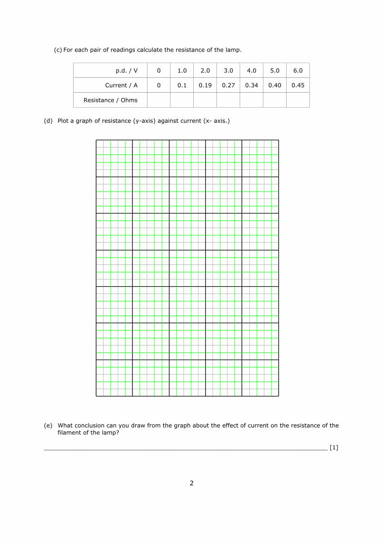
(c) For each pair of readings calculate the resistance of the lamp.
p.d. / V 0 1.0 2.0 3.0 4.0 5.0 6.0
Current / A 0 0.1 0.19 0.27 0.34 0.40 0.45
Resistance / Ohms
(d) Plot a graph of resistance (y-axis) against current (x- axis.)
(e) What conclusion can you draw from the graph about the effect of current on the resistance of thefilament of the lamp?
______________________________________________________________________________ [1]

Current characteristics 2
Name & Set
1 In a physics book a student reads that the resistance of a piece of wire depends upon• its cross-sectional area• its length• the material of which it is made
The student decides to examine how the cross-sectional area of a piece of wire affects itsresistance He selects some pieces of resistance wire, each 1 m long.(a) (i) Why should all the pieces of wire be made of the same material?
______________________________________________________________________________
______________________________________________________________________________
___________________________________________________________________________ [2](ii) Why should they all be the same length?
______________________________________________________________________________
______________________________________________________________________________
___________________________________________________________________________ [2](b) (i) Using the standard symbols for electrical components draw a circuit diagram for the circuit
that you would use in this experiment in the space below.
[4]
(i) Write down in words in the space below the equation that links RESISTANCE, CURRENT andVOLTAGE.
[2]
(ii) What measurements would you make to determine the resistance of the wire?
_____________________________________________________________________________
___________________________________________________________________________ [2]
2
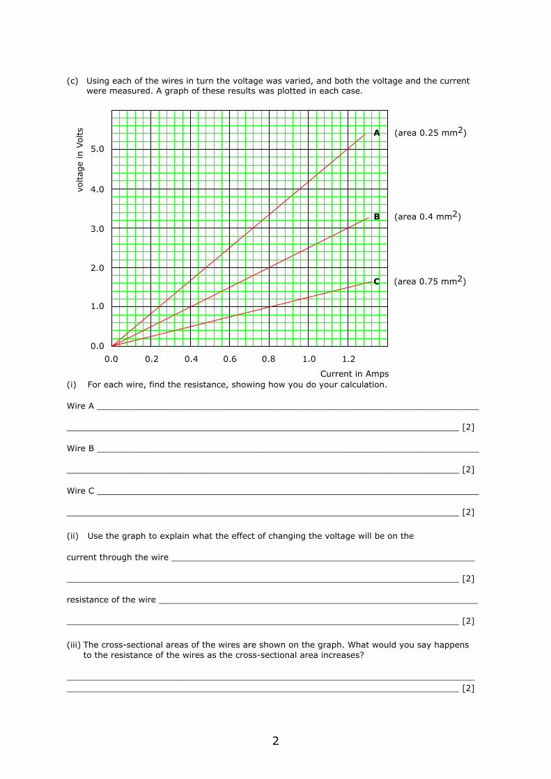
(c) Using each of the wires in turn the voltage was varied, and both the voltage and the currentwere measured. A graph of these results was plotted in each case.
(i) For each wire, find the resistance, showing how you do your calculation.
Wire A _________________________________________________________________________
___________________________________________________________________________ [2]
Wire B _________________________________________________________________________
___________________________________________________________________________ [2]
Wire C _________________________________________________________________________
___________________________________________________________________________ [2]
(ii) Use the graph to explain what the effect of changing the voltage will be on the
current through the wire __________________________________________________________
___________________________________________________________________________ [2]
resistance of the wire _____________________________________________________________
___________________________________________________________________________ [2]
(iii) The cross-sectional areas of the wires are shown on the graph. What would you say happensto the resistance of the wires as the cross-sectional area increases?
_________________________________________________________________________________________________________________________________________________________ [2]
0.0 0.2 0.4 0.6 0.8 1.0 1.2
1.0
2.0
3.0
4.0
5.0
voltag
e in
Volts
Current in Amps
A (area 0.25 mm2)
B (area 0.4 mm2)
C (area 0.75 mm2)
0.0