water tank depth sensor - econodoseconodos.net/.../2011/10/water-tank-depth-sensor.pdf · water...
TRANSCRIPT

!"#"$"%"&"'"("")*"!
!!
Water Tank Depth Sensor
Water is a precious resource in many parts of the world and many people rely on water tanks to supplement their water supply by storing collected rainwater or water pumped from a well or bore. But how do you measure how full a tank is? Tanks are constructed of opaque material to prevent algae growth and are often kept closed up to prevent mosquito infestation or access by rodents, so it’s inconvenient to physically look inside. And besides, having a way to measure tank depth electronically opens up a world of possibilities, such as automatic control of pumps to fill tanks when they get low or to disable irrigation systems when not enough water is available.
The obvious way to measure tank depth is by placing a series of conductive pickups at various heights inside the tank and measure the resistance between them. For example, you could attach ten exposed terminals at equal intervals on a length of material such as PVC tubing, and insert it into a tank vertically to measure the depth in 10 percent increments simply by reading the resistance between the bottom terminal and each of the terminals above it. The downside to this approach, though, is that you’ll need to do a lot of wiring and you’ll also need to read an analog input for every individual terminal. Also keep in mind that most Arduino designs have no more than six analog inputs. There are ways around this, such as using a resistor ladder, but it can still end up being quite time-consuming and still give very poor resolution.
This project works a little differently. It uses a device called a pressure transducer to measure the water pressure at the bottom of the tank, and from that measurement it calculates how full the tank is. Water pressure increases by about 9.8kPa per meter of depth (varying slightly depending on the purity of the water and other factors), so a full tank 1.5 meters tall will have a pressure at the bottom of about 14.7kPa above ambient atmospheric pressure. The “above ambient atmospheric pressure” part is important: it’s not enough to simply measure the pressure at the bottom of the tank using a single-ended “absolute” pressure transducer because varying climate conditions will alter the reading as the air pressure changes. That’s why this project uses a “differential” pressure transducer that has two inlets. By leaving one inlet open to the atmosphere and connecting the other to the bottom of the tank, the transducer will output the difference between the two. This approach provides automatic compensation for varying air pressure and giving a constant reading for constant depth even if the weather changes. The Arduino then reads the output of the transducer and reports the depth of the tank.
In this project we will use an Ethernet shield so the Arduino can connect to an online datalogging service called Pachube (www.pachube.com) to generate graphs of water depth over time, but you could also have it make decisions based on water depth to control items such as a water pump or irrigation system solenoid. You can see the required parts in Figure 12-1 and the complete schematic in Figure 12-2.
209

CHAPTER 12 WATER TANK DEPTH SENSOR
Parts Required 1 Arduino Duemilanove, Arduino Pro, Seeeduino, or equivalent
1 Ethernet shield or WiShield
1 Prototyping shield
1 MPX2010DP or MPX2053DP differential pressure transducer (see text)
1 LM324 op-amp
1 14-pin IC socket
4 1K resistors
3 22K resistors
1 1K multiturn variable resistor
1 10K multiturn variable resistor
2 10nF MKT capacitors (typically marked “103”)
1 100nF MKT capacitor (typically marked “104”)
10cm of 4mm tubing (commonly used for aquarium air pumps)
3 4mm internal-diameter cable glands (typically sold as “3 to 6.5mm”)
1 small weatherproof PVC box (we used 64mm 58mm 35mm)
1 medium weatherproof PVC box with O-ring seal (we used 115mm 90mm 55mm)
2 meters flexible four-conductor wire (such as security cable or telephone wire)
Source code available from www.practicalarduino.com/projects/water-tank-depth-sensor.
210

CHAPTER 12 WATER TANK DEPTH SENSOR
Figure 12-1. Parts required for water tank depth sensor
Figure 12-2. Schematic of water tank depth sensor
211

CHAPTER 12 WATER TANK DEPTH SENSOR
Instructions If you come from a software background and haven’t done much work with electronics before, this circuit can look a little intimidating, particularly as it deals with analog voltage levels rather than nice, neat, “on or off” digital levels.
The key to understanding the circuit is to temporarily ignore the section in the top right of the schematic shown in Figure 12-2 and just look at the overall symmetry of the central section, starting from the MPX2010DP differential pressure transducer on the left.
Before getting into the details, though, you need to consider the requirements for the pressure transducer. The MPX2010DP is fairly commonly available, but is only rated to 10kPa, equivalent to the pressure from just over a meter of water depth. In testing we’ve used it in tanks up to two meters deep and it’s performed fine, but keep in mind that doing so is pushing the transducer beyond the manufacturer’s specifications, and if you need to measure depth of a larger tank you may need to use a part with a higher pressure rating. For example, at the high end of the scale, the MPX2053DP is a similar part that is rated to 50kPa—equivalent to 5m of water depth.
The transducer has two ports protruding from it and will generate a tiny voltage differential between its outputs that is proportional to the difference in pressure between those ports. If the pressure applied to both ports is the same, the sensor will remain in equilibrium and the voltage on both outputs will be about half of the supply voltage, or about 2.5V in our case. The difference between them will, therefore, be zero. If the pressure applied to port 1 is higher than the pressure applied to port 2, the voltage on pin 2 will rise and the voltage on pin 4 will fall. The variation is tiny, though: a pressure differential of 10kPa will cause a voltage differential of only about 12.5mV.
That’s too small to be measured reliably by an analog input on an Arduino, so the rest of the circuit is dedicated to amplifying that voltage differential up to a higher level.
The two transducer outputs are fed into the inputs of “operational amplifiers,” more commonly referred to simply as “op-amps.” Op-amps are perhaps one of the most commonly manufactured nonpassive electronic devices ever, and they work by taking the difference between two inputs and outputting a signal that is an amplification of that difference. As such, we could have just used a single op-amp and fed both outputs from the transducer into it, but that wouldn’t have provided enough gain to raise the signal to a level that the Arduino can read reliably. To overcome this we use a compound amplifier circuit that amplifies each of the outputs individually, driving the high signal further above the 2.5V reference point and the low signal further below 2.5V. The result is that the voltage difference between pins 1 and 7 on the outputs of op-amps 1 and 2 will be greater than the voltage difference between the transducer outputs.
The combination of the 22K resistors and 10nF capacitors linking the output of op-amps 1 and 2 back to their inputs provide “negative feedback,” with a rise in output level decreasing the gain to maintain stability. It helps the amplifier maintain a steady state and may look counterintuitive, but this is a very common configuration for op-amps and you’ll see it in many analog circuits. For more explanation of negative feedback op-amp circuits, see the Wikipedia page at en.wikipedia.org/wiki/Operational_amplifier.The 1K multiturn variable resistor joining the negative op-amp inputs together also controls the gain so that the overall effectiveness of the amplification circuit can be altered to best suit the characteristics of the transducer. Most variable resistors are single-turn, and adjust from 0R to their maximum rating through only about 270 degrees of rotation. That doesn’t provide enough sensitivity when tuning an op-amp circuit, though, so we’ve specified multiturn variable resistors that are commonly available in either 10-turn or 20-turn versions. Multiturn variable resistors have a tiny threaded rod inside to gear down the turns you apply and provide very fine control of their resistance.
The outputs from the op-amps in the center of the schematic shown in Figure 12-2 then pass through a pair of 1K resistors and into the two inputs of op-amp 3, which once again amplifies the difference to drive an even greater variation on its output on pin 8. The result is that tiny variations in
212

CHAPTER 12 WATER TANK DEPTH SENSOR
voltage across the transducer outputs on the extreme left of the circuit cause much larger voltage variations at the output on the far right where it will be connected to an Arduino analog input.
That’s not quite the whole story, though. The section of the circuit we’ve been ignoring up in the top right also comes into play, biasing the input on pin 12 of op-amp 4, which in turn biases the input on pin 10 of op-amp 3. When tuning the circuit, the 10K variable resistor is adjusted until the output of op-amp 4 at pin 14 is about 1V when the pressure difference on the transducer is zero. This provides a base level of 1V to the Arduino input when the tank is empty.
Having set the bias for an empty reading, the 1K variable resistor controlling the gain on the first two op-amps is adjusted until the output to the Arduino is about 3V when port 1 of the transducer is exposed to the pressure at the bottom of a full tank. The circuit, therefore, has an output voltage that swings linearly between about 1V for an empty tank and 3V for a full tank, a variation of 2V.
So why bother with the bias to pull the “empty” value up to 1V and limit the gain to set the full value at 3V? Why not remove the “empty” bias and increase the amplification to provide a wider swing from 0V to 5V on the output and take advantage of the full input range of the Arduino’s analog to digital converters?
The reason is that the performance characteristics of an op-amp typically don’t allow it to provide a full rail-to-rail swing, and even if they could do so the linearity of the output could be compromised toward the edge of the range. Limiting it to a 1V-to-3V swing is well within the performance rating of the LM324 op-amp we’re using, though, and avoids the non-linear regions toward the edges.
Looking at the schematic in Figure 12-2 you may be a little confused by the fact that it shows four op-amps, while looking at the photos there is only one integrated circuit. That’s because the LM324 is a quad package with four op-amps inside one physical chip, all sharing common power and ground connections. Perfect for this application. What you see in the schematic is the logical representation of the four op-amps contained in the package because as far as the circuit is concerned they are separate devices. The fact that they’re in the same physical package is just extra convenience for us when it comes to assembly.
Assemble the Shield Begin by fitting the 14-pin IC socket, noting the direction of the orientation marker: the little notch in one end. That notch indicates which end of the chip is pin 1, which in the photo shown in Figure 12-3 is in the bottom right corner of the IC socket. The rest of the pins are numbered counterclockwise up the right side to 7 in the top right, 8 in the top left, and down to 14 in the bottom left with the socket oriented as shown in the photo. Note that this is rotated 180 degrees compared to most IC datasheets, which typically show the orientation marker at the top with pin 1 on the top left. In this case, though, it made sense to mount the chip upside down so the supporting parts are nearer the appropriate IC pins.
Next insert the resistors immediately adjacent to the socket, bending the leads underneath the shield to form jumpers to adjacent pads where necessary. The pair of 10nF MKT capacitors (probably marked “103K”) just to the right of the socket go in next, and then the resistors are mounted vertically next to them. Then fit the 10K multiturn variable resistor on the left (marked “103”), and the 100nF MKT capacitor next to it (marked “104K”) along with the jumpers that link them to ground and +5V. The 1K multiturn variable resistor and associated links go on the right.
For convenience when assembling and testing the system we fitted a 4-pin oriented male header for the cable to the pressure transducer. If you prefer, you can solder a lead for the transducer directly to the board.
213

CHAPTER 12 WATER TANK DEPTH SENSOR
Figure 12-3. Parts assembled on shield ready for insertion of LM324 op-amp into the IC socket
That’s all the hard assembly work done. The only thing left to do on the prototyping shield is to install a jumper lead that connects pin 8 of the op-amp to analog input 0 on the Arduino. The 1K resistor mounted on the end connected between pins 8 and 9 provides a very convenient mounting point for one end of the jumper lead, which then stretches across the board to analog input 0. Connecting the op-amp output to the analog input with a jumper lead like this makes it easy later if you want to switch to a different input so you can stack multiple shields.
Finally, insert the LM324 op-amp into the socket. Inserting ICs can be tricky at first because the legs always spread out wider than the holes in the socket. You can buy special tools for inserting ICs into sockets but they’re really not necessary on a small IC like an LM234: it’s just as easy to bend the pins in a little until they align with the holes in the socket. Try putting the IC down on your workbench on one edge, grip it on the ends, and very carefully push down to bend the pins in. Turn the IC over and do the same to the other side so it will fit into the socket neatly. Be cautious in applying pressure to the pins, but don’t be afraid. The worst that can happen is you bend them too far and have to bend them back.
You’ll also notice a short link near the bottom left of the board to connect one of the LEDs provided on this particular prototyping shield to ground. The other end of the LED is connected to +5V via a 1K current-limiting resistor. That LED is included just to show when the shield is powered up and is entirely optional, so it doesn’t appear in the circuit diagram.
214

CHAPTER 12 WATER TANK DEPTH SENSOR
Figure 12-4. Fully assembled tank depth sensor shield
Put the shield aside for a while and move on to assembling the sensor housing.
Determine Sensor Installation Method Although the basic circuit will be the same regardless of how you mount it, this project has several options regarding how you expose the transducer to the pressure at the bottom of the tank while also exposing it to atmospheric pressure outside the tank. Before starting construction of the sensor assembly you need to think about how it will be connected.
There are four basic options for installation. The first, and most obvious, is to fit the Arduino and shield into a weatherproof case mounted just above the tank with one transducer hose exposed to the atmosphere and the other running down inside the tank with a weight attached to hold it on the bottom (see Figure 12-5). This can work in the short term but can cause problems over time due to diffusion of air in the tube into the water in the tank. Eventually, the water level will rise up the hose with the result that your Arduino will be reading the pressure from the height of the top of the water in the hose, not the pressure at the bottom of the hose. If left in long enough, a full tank will appear to be slowly draining until you get an “empty” reading. Of course, you can periodically pull the hose out of the tank and drain it to restore accuracy, but it’s not really a good long-term solution.
215

CHAPTER 12 WATER TANK DEPTH SENSOR
Figure 12-5. Pressure transducer mounted above tank
The second option is to mount the entire Arduino and sensor inside a waterproof container submerged at the bottom of the tank with a short hose exposed to the water and a long hose running up and exiting the tank to provide an atmospheric pressure reference (see Figure 12-6). You’ll also need to pass the power and data cabling up through the tank, and it goes without saying that electricity and water don’t mix, so you need to be very careful to totally seal the assembly! Plastic project boxes with waterproof O-ring seals are fairly commonly available, and combined with waterproof cable glands and liberal doses of silicone sealant you should be able to build an assembly that can withstand long-term submersion without problems. Getting access to the Arduino for maintenance, though, could be quite tricky, and condensation in the atmospheric tube could build up over time.
216

CHAPTER 12 WATER TANK DEPTH SENSOR
Figure 12-6. Pressure transducer and Arduino mounted inside tank
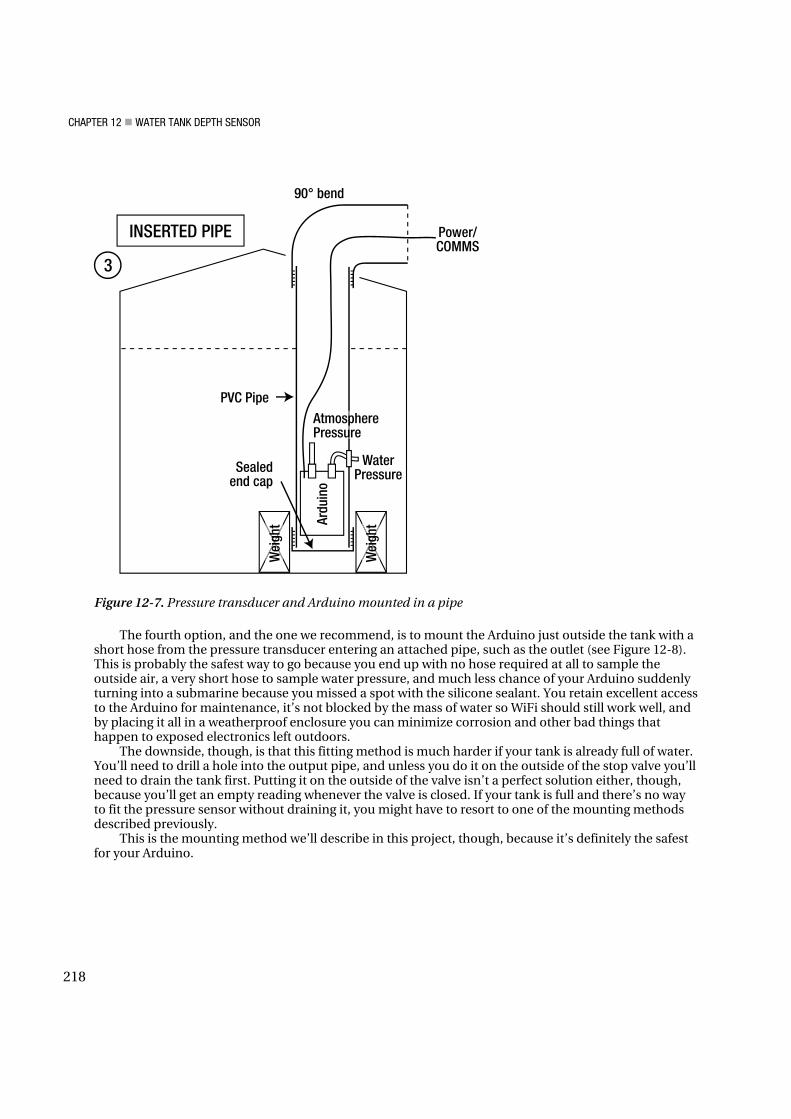
The third option is a clever variation on the previous approach that replaces the project box with a length of large-diameter pipe, sealed at one end and protruding from the bottom of the tank all the way up out of the water, or alternatively, a sealed box with a pipe attached. An Arduino with two shields stacked on top will slide easily into the end of a 75mm (3-inch) PVC pipe, and you can then pass a short length of hose out through a cable gland to sample the water pressure near the bottom of the tank. A 2m length of 75mm pipe can be inserted vertically into a tank with the top protruding, but be warned that it will displace a surprisingly large volume of water and will be extremely buoyant, so you will need to attach a significant weight to hold it down (see Figure 12-7).
You’ll also need to make sure the top isn’t directly exposed to the weather so the pipe fills up and drowns your Arduino first time it rains! And you’ll be limited to using cabled Ethernet rather than WiFi for communications because a WiFi shield surrounded by several tons of water will have no range at all. Overall, though, this is a very practical way to do it and gives you reasonable access to the Arduino for future maintenance, but watch for corrosion over time since air can circulate so easily all the way down to the circuitry.
217
CHAPTER 12 WATER TANK DEPTH SENSOR
Figure 12-7. Pressure transducer and Arduino mounted in a pipe
The fourth option, and the one we recommend, is to mount the Arduino just outside the tank with a short hose from the pressure transducer entering an attached pipe, such as the outlet (see Figure 12-8). This is probably the safest way to go because you end up with no hose required at all to sample the outside air, a very short hose to sample water pressure, and much less chance of your Arduino suddenly turning into a submarine because you missed a spot with the silicone sealant. You retain excellent access to the Arduino for maintenance, it’s not blocked by the mass of water so WiFi should still work well, and by placing it all in a weatherproof enclosure you can minimize corrosion and other bad things that happen to exposed electronics left outdoors.
The downside, though, is that this fitting method is much harder if your tank is already full of water. You’ll need to drill a hole into the output pipe, and unless you do it on the outside of the stop valve you’ll need to drain the tank first. Putting it on the outside of the valve isn’t a perfect solution either, though, because you’ll get an empty reading whenever the valve is closed. If your tank is full and there’s no way to fit the pressure sensor without draining it, you might have to resort to one of the mounting methods described previously.
This is the mounting method we’ll describe in this project, though, because it’s definitely the safest for your Arduino.
218

CHAPTER 12 WATER TANK DEPTH SENSOR
Figure 12-8. Pressure transducer and Arduino mounted near outlet
Assemble the Sensor Housing If you intend to mount the sensor submerged inside the tank you will need to use your own creativity to determine a method to house and seal it. A good starting point would be to assemble the sensor box following our instructions and then add large quantities of silicone sealant and a long tube attached to transducer port 2 to exit the top of the tank.
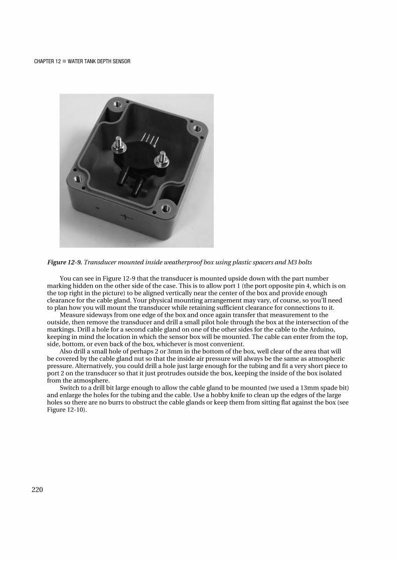
For our prototype, we mounted the pressure transducer inside a small PVC project box by drilling holes in the back of the box and attaching the transducer using small bolts and plastic spacers to hold it 10mm clear of the back (see Figure 12-9). The box already had small spacers molded in place, but because they were in the wrong location and not quite long enough we didn’t use them and added our own instead. Spacers are necessary to provide enough clearance for the sensor hose to be attached to the port on the transducer, and without them the transducer port won’t have enough clearance from the back of the box.
After test-fitting the transducer in the box, measure the distance from the front edge of the box to the center of the port on the inside of the box and then use a felt-tip pen to transfer the measurement onto the outside.
219
CHAPTER 12 WATER TANK DEPTH SENSOR
Figure 12-9. Transducer mounted inside weatherproof box using plastic spacers and M3 bolts
You can see in Figure 12-9 that the transducer is mounted upside down with the part number marking hidden on the other side of the case. This is to allow port 1 (the port opposite pin 4, which is on the top right in the picture) to be aligned vertically near the center of the box and provide enough clearance for the cable gland. Your physical mounting arrangement may vary, of course, so you’ll need to plan how you will mount the transducer while retaining sufficient clearance for connections to it.
Measure sideways from one edge of the box and once again transfer that measurement to the outside, then remove the transducer and drill a small pilot hole through the box at the intersection of the markings. Drill a hole for a second cable gland on one of the other sides for the cable to the Arduino, keeping in mind the location in which the sensor box will be mounted. The cable can enter from the top, side, bottom, or even back of the box, whichever is most convenient.
Also drill a small hole of perhaps 2 or 3mm in the bottom of the box, well clear of the area that will be covered by the cable gland nut so that the inside air pressure will always be the same as atmospheric pressure. Alternatively, you could drill a hole just large enough for the tubing and fit a very short piece to port 2 on the transducer so that it just protrudes outside the box, keeping the inside of the box isolated from the atmosphere.
Switch to a drill bit large enough to allow the cable gland to be mounted (we used a 13mm spade bit) and enlarge the holes for the tubing and the cable. Use a hobby knife to clean up the edges of the large holes so there are no burrs to obstruct the cable glands or keep them from sitting flat against the box (see Figure 12-10).
220

CHAPTER 12 WATER TANK DEPTH SENSOR
Figure 12-10. Transducer mounting box with holes drilled for cable glands and pressure equalization
The purpose of the cable glands is not to provide a watertight seal, because the box needs to be open to the atmosphere anyway to sample ambient atmospheric pressure. Rather, the cable glands provide physical support for the tubing and cable and protect the transducer port from mechanical strain if the tubing or box are moved.
If you don’t have any cable glands available you can make do without them, but you will need to make sure the tubing has good mechanical support as it enters the box. You could drill the hole out to the same size as the outside diameter of the tubing so that it fits through but is a snug fit. After everything is assembled and tested, you could then apply silicone sealant to the tube and cable to give them some mechanical support.
Before mounting the transducer back in the box it’s a good idea to put a drop of mineral oil (commonly sold as baby oil) into each port. The mineral oil will help protect the transducer from water.
Fit one end of the tubing onto transducer port 1 while it’s still out of the box. The tubing should be a very tight fit onto the transducer and you might have quite a bit of trouble getting it on. A handy trick is to boil some water and pour it into a mug, then hold the end of the tubing in the hot water for a minute to soften it up. Slide it onto the transducer while it’s still hot and it should go on much more easily, then when it cools down it will shrink and form a tight seal. Just remember that if the tube isn’t sealed properly onto the transducer port the water pressure from the tank may cause it to spray out inside the box, quickly flooding your expensive pressure transducer.
Slide the tubing through the cable gland mounted in the box until the transducer is in the correct place and is aligned with the spacers. Bolt it in again, and tighten up the cable gland around the tubing enough to give it good support without squashing it closed (see Figure 12-11).
221

CHAPTER 12 WATER TANK DEPTH SENSOR
Figure 12-11. Transducer mounted with pressure hose fitted and cable gland for connection to Arduino in
place
To save you time later it’s best to do a test-fit of the four-core cable at your actual tank, running it from the location in which you’ll mount the sensor box to the location you’ll mount the Arduino. Add a meter or so of extra length for safety and cut it to length so you can finish the assembly in the comfort of your workbench instead of trying to solder things together out in the yard.
Having cut it to length, insert one end of the four-core cable into the box through the other cable gland and strip back the ends, then solder them onto the pins of the pressure transducer. Make a note of which color connects to each pin for future reference. We used short lengths of heat-shrink tubing over each joint to help keep moisture off them.
Pin 1 on the transducer is marked with a tiny notch, with port 2 directly opposite pin 1, and port 1 directly opposite pin 4 (see Figure 12-12). The pin assignements are shown in Table 12-1.
Figure 12-12. Pin numbers and ports for pressure transducer
222

CHAPTER 12 WATER TANK DEPTH SENSOR
Table 12-1. Pressure transducer pin assignments
Pin Purpose
1 Ground
2 +Vout
3 Power
4 -Vout
Our cable had red, green, white, and yellow leads inside, so we connected black to pin 1 for ground, white
to pin 2 for the +V output, red to pin 3 for +5V, and yellow to pin 4 for the -V output (see Figure 12-13).
Figure 12-13. Transducer box fully assembled and ready to be closed up
The sensor assembly is all ready to go, so screw the lid on and put it aside.
Assemble the Arduino Housing Mounting the Arduino along with the WiShield and the tank depth shield in a weatherproof box follows pretty much the same process as building the sensor assembly. Sit the Arduino in the bottom of the box and mark the location of the mounting holes. In our prototype we wanted to provide external access to the USB and power connections with everything mounted in place, so allowance had to be made for the
223

CHAPTER 12 WATER TANK DEPTH SENSOR
distance the USB socket protrudes from the board. We marked the position of the mounting holes with the Arduino pushed up hard against the bottom of the box, then measured the distance that the USB socket protruded and offset all the markings by that same distance toward the bottom. This way, when the USB and power holes are cut, the Arduino will slide into them and the mounting holes will be in the correct location (see Figure 12-14).
Figure 12-14. Determining the location of the mounting holes
Cutting square holes is always awkward. We started by drilling a small hole in each corner, then drilled holes down each edge. The major section of the center of each hole was then clipped out with wire cutters before the edges were trimmed straight with a hobby knife.
Also drill a hole for a cable gland, once again keeping in mind where the cable will be mounted. We fitted the cable so it exits on the right-hand side of the box.
Fit M3 bolts up through the holes in the back of the box and sit 10mm spacers on top of them, then slide the Arduino down into the holes in the bottom and onto the bolts. This might take a bit of experimentation, but it shouldn’t be too difficult if you let the bolts slide back down a little bit while you get the Arduino in position.
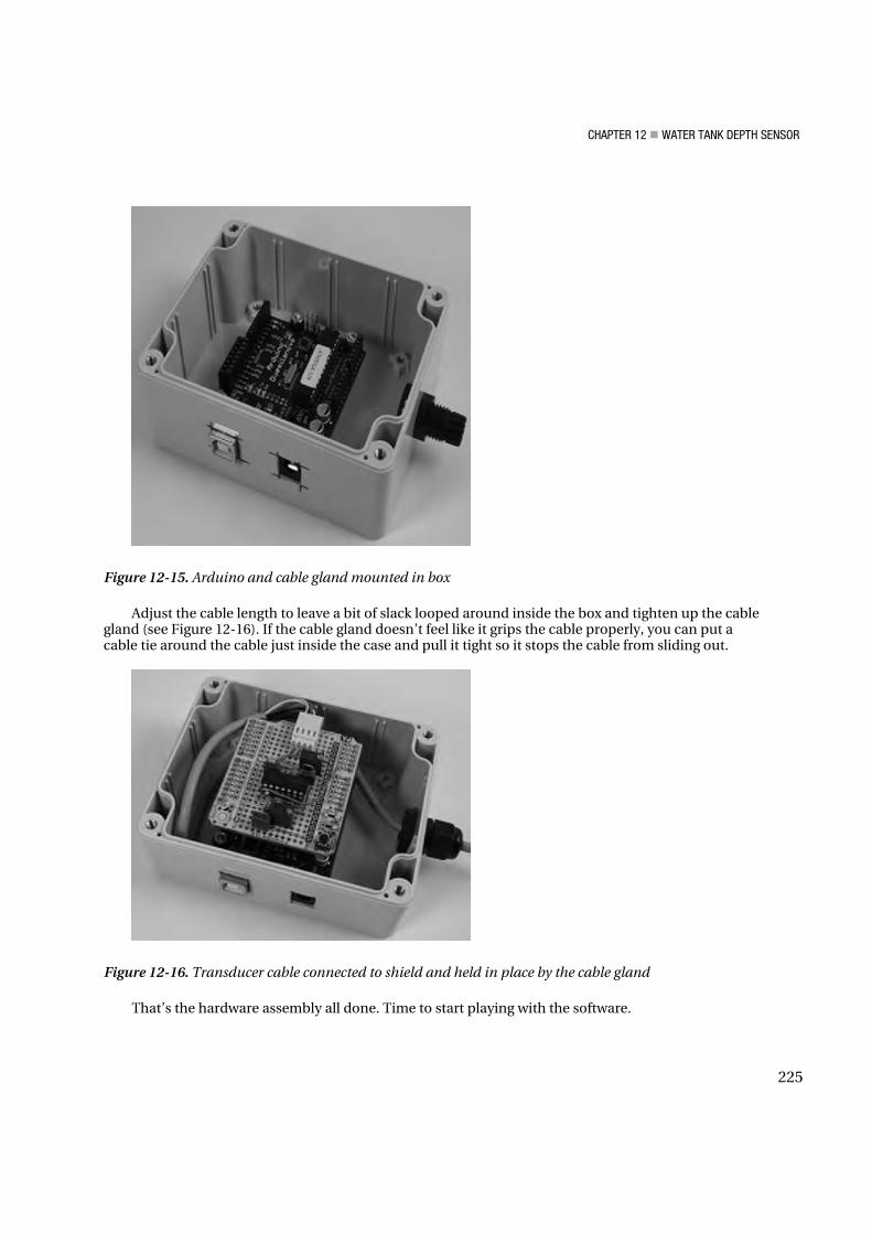
Put insulating washers over the bolts on top of the Arduino, followed by nuts, then tighten the bolts to hold everything firmly in place (see Figure 12-15).
With the Arduino mounted in the box plug the WiShield on top. One very neat thing about the WiShield is that it ships with long-lead female headers and all the parts on the board are kept low to make it stackable, so for this project it’s perfect: after plugging the WiShield into your Arduino, just plug the prototyping shield on top to create a triple-decker assembly with the connector for the sensor cable easily accessible.
Slide the four-core sensor cable through the cable gland, strip back the insulation from the end of the cable and “tin” the ends with solder. Either solder the cable directly to the prototyping shield or, if you fitted a 4-pin female header to the shield, solder it to a 4-pin male header and plug it in.
224
CHAPTER 12 WATER TANK DEPTH SENSOR
Figure 12-15. Arduino and cable gland mounted in box
Adjust the cable length to leave a bit of slack looped around inside the box and tighten up the cable gland (see Figure 12-16). If the cable gland doesn’t feel like it grips the cable properly, you can put a cable tie around the cable just inside the case and pull it tight so it stops the cable from sliding out.
Figure 12-16. Transducer cable connected to shield and held in place by the cable gland
That’s the hardware assembly all done. Time to start playing with the software.
225
CHAPTER 12 WATER TANK DEPTH SENSOR
Install the WiShield Library and Driver The WiShield supports 802.11b at 1 and 2Mbps (the Arduino couldn’t keep up with anything faster anyway!) and even supports WEP and WPA/WPA2, in case you want to keep your top-secret water tank depth data secure from prying wardrivers. It communicates with the Arduino using SPI, which ties up digital I/O lines 10, 11, 12, and 13, along with line 2 for an interrupt connection and pin 9 for the shield’s status LED, so it’s important to keep those free in your project. Because we’re only using one of the analog inputs, that’s not a problem for us in this project.
The WiShield needs two software components to function correctly: the WiShield library from AsyncLabs, and the driver code from ZeroG Wireless. Unfortunately, the driver from ZeroG Wireless hasn’t been released under a FOSS (Free / Open Source Software) license and therefore can’t be distributed along with the library, so you need to install the library and then download and install the driver separately. More information is available from the AsyncLabs web site at www.asynclabs.com, or you can follow along the steps here.
Start by downloading the WiShield library using the WiShield Library link from the project page on the Practical Arduino web site. Extract it on your local computer and rename the directory to WiShield if necessary, and move it into your sketchbook/libraries directory so the Arduino environment can see it.
Next, go to the driver page using the WiShield Driver link from the project page. There you’ll see the terms under which the driver has been made available. Click the WiShield Driver Download link at the bottom of the page to get an archive called wishield-g2100-driver.zip. Extract the ZIP file, and move the g2100.c and g2100.h source files into your sketchbook/libraries/WiShield/ directory.
The WiShield library supports several different modes. The default mode is the APP_WEBSERVER mode, which should run on most Arduinos but has limitations such as not being able to run as both a client and server simultaneously. An alternative mode called APP_WISERVER will run on any Arduino with an ATMega328P or better CPU, which includes the Duemilanove and most current third-party equivalents such as the Arduino Pro. Any reasonably modern Arduino should be able to run in APP_WISERVER mode so that’s what we’ll be using.
To switch the library into APP_WISERVER mode, open up the file sketchbook/libraries/WiShield/apps-conf.h and go to about line 39. Comment out the existing APP_WEBSERVER entry and uncomment the APP_WISERVER entry a few lines below it so that it looks like the following:
//#define APP_WEBSERVER //#define APP_WEBCLIENT //#define APP_SOCKAPP //#define APP_UDPAPP #define APP_WISERVER
With everything in place and those changes made to the library, you can now open up the Arduino IDE
and have access to the WiShield library and example code. Note, though, that there are examples provided for several different modes: some examples only work in APP_WEBSERVER mode and some only work in APP_WISERVER mode. The ones that work in APP_WISERVER mode are all prefixed with “Simple.”
To test that the WiShield is working correctly, open up the example at File Examples WiShield SimpleServer, adjust the network settings and WiFi encryption settings to suit your network, compile it, and upload it to your Arduino. If you’re running on an open network it should associate pretty much immediately and the red status LED will illuminate to show it’s joined the wireless network. If you’re running WPA the process may take 30 seconds or so while the WiShield negotiates with your access point, but eventually the red LED will come to life to show that your Arduino is now on your network.
Open up a web browser, go to the IP address you set in the program, and you should see a “Hello World!” message from your Arduino.
226

CHAPTER 12 WATER TANK DEPTH SENSOR
The SimpleServer example implements logging via the serial connection, so if you’re curious to see what the Arduino is doing you can open the serial monitor in the IDE and set the baud rate to 57600bps. Be warned, though, that with most modern Arduinos the act of opening the serial connection forces it to reset, and every time the Arduino boots up it may take another 30 seconds or so to reassociate with your wireless network. Lots of patience is required if you keep opening and closing the serial monitor.
Congratulations! Your Arduino is now connected to your WiFi network as a web server.
Load the Tank-Level Sketch The tank-level reporting sketch is based on the SimpleServer example code with a simple addition to read an analog input and include the value in the web page sent back to the browser.
The sketch starts by including the WiShield library. Because we’re using it in APP_WISERVER mode we include the WiServer.h header file instead of the WiShield.h header referenced in some of the other included examples. The sketch then defines a couple of tokens to make the code further down a bit more readable.
#include <WiServer.h> #define WIRELESS_MODE_INFRA 1 #define WIRELESS_MODE_ADHOC 2
The sketch needs to know certain configuration values to connect to your WiFi network. These are
set using a series of arrays and need to be changed to suit your requirements. The basic network settings are the IP address of your Arduino (which must be unique on your
network), the IP address of your router, and the subnet mask for your network. Note that most of the time you see an IP address it’s represented in “dotted-quad” format, but in this case each quad is stored as a different element in an array so they have to be separated by commas instead of periods.
unsigned char local_ip[] = {10,0,1,200}; unsigned char gateway_ip[] = {10,0,1,1}; unsigned char subnet_mask[] = {255,255,255,0};
The wireless-specific settings start with the SSID (service set identifier) of your access point. This is
the WiFi network name that you see on your computer when selecting a network. Maximum length for the SSID is 32 characters.
const prog_char ssid[] PROGMEM = {"YourSSID"};
You then need to specify the security type. The supported settings are shown in Table 12-2
227
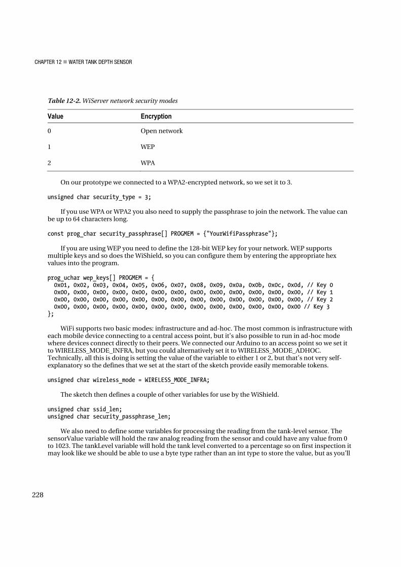
CHAPTER 12 WATER TANK DEPTH SENSOR
Table 12-2. WiServer network security modes
Value Encryption
0 Open network
1 WEP
2 WPA
On our prototype we connected to a WPA2-encrypted network, so we set it to 3.
unsigned char security_type = 3; If you use WPA or WPA2 you also need to supply the passphrase to join the network. The value can
be up to 64 characters long.
const prog_char security_passphrase[] PROGMEM = {"YourWifiPassphrase"}; If you are using WEP you need to define the 128-bit WEP key for your network. WEP supports
multiple keys and so does the WiShield, so you can configure them by entering the appropriate hex values into the program.
prog_uchar wep_keys[] PROGMEM = { 0x01, 0x02, 0x03, 0x04, 0x05, 0x06, 0x07, 0x08, 0x09, 0x0a, 0x0b, 0x0c, 0x0d, // Key 0 0x00, 0x00, 0x00, 0x00, 0x00, 0x00, 0x00, 0x00, 0x00, 0x00, 0x00, 0x00, 0x00, // Key 1 0x00, 0x00, 0x00, 0x00, 0x00, 0x00, 0x00, 0x00, 0x00, 0x00, 0x00, 0x00, 0x00, // Key 2 0x00, 0x00, 0x00, 0x00, 0x00, 0x00, 0x00, 0x00, 0x00, 0x00, 0x00, 0x00, 0x00 // Key 3 };
WiFi supports two basic modes: infrastructure and ad-hoc. The most common is infrastructure with
each mobile device connecting to a central access point, but it’s also possible to run in ad-hoc mode where devices connect directly to their peers. We connected our Arduino to an access point so we set it to WIRELESS_MODE_INFRA, but you could alternatively set it to WIRELESS_MODE_ADHOC. Technically, all this is doing is setting the value of the variable to either 1 or 2, but that’s not very self-explanatory so the defines that we set at the start of the sketch provide easily memorable tokens.
unsigned char wireless_mode = WIRELESS_MODE_INFRA;
The sketch then defines a couple of other variables for use by the WiShield.
unsigned char ssid_len; unsigned char security_passphrase_len;
We also need to define some variables for processing the reading from the tank-level sensor. The
sensorValue variable will hold the raw analog reading from the sensor and could have any value from 0 to 1023. The tankLevel variable will hold the tank level converted to a percentage so on first inspection it may look like we should be able to use a byte type rather than an int type to store the value, but as you’ll
228

CHAPTER 12 WATER TANK DEPTH SENSOR
see in a moment that wouldn’t actually work. Finally, the TANK_SENSOR define is to specify which analog input the sensor is connected to. The shield design in this project uses analog input 0.
int sensorValue = 0; int tankLevel = 0; #define TANK_SENSOR 0
The tank-level sensor won’t provide a value that varies all the way from 0V when empty to +5V when
full, so we need some calibration values that are used later in the program to adjust the lower and upper levels of the read range. These will need to be altered to suit your specific installation using a procedure that will be explained in a moment.
#define TANK_EMPTY 0 #define TANK_FULL 1023
The setup function is simple, but the WiServer.init() function is worth taking a look at. It accepts an
argument that specifies the callback function to be executed in response to a connection request, and in this case we’ve told it to use the function sendWebPage(). This is a bit like setting up an interrupt because the sendWebPage() function is never called directly in the program, but by defining it and passing it to WiServer.init() it will be invoked automatically at the appropriate time.
void setup() { WiServer.init(sendWebPage);
Next, the sketch opens a serial connection to the host so it can send status messages back to you,
and enables “verbose” mode so the server will send log messages via that connection.
Serial.begin(38400); WiServer.enableVerboseMode(true); }
The main program loop is trivial. All it does is repeatedly call the WiServer.server_task() method so
that incoming data queued by the WiShield will be processed. Without this, a connection request from your browser will arrive at the WiShield and sit in the buffer without ever being acted on.
void loop(){ WiServer.server_task(); delay(10); }
The last function generates the web page to send back to the browser. It’s just a slightly extended
version of the example included with the WiShield library with the addition of the reading from the tank-depth sensor connected to analog input pin 0.
boolean sendWebPage(char* URL) {
Before sending back the page the function makes a call to analogRead() to sample the sensor value.
The theoretical range of the sensorValue variable is anywhere from 0 for a 0V reading on that input through to 1023 for a +5V reading, but because the reading will only swing from about 1V when empty to 3V when full the actual range is more limited. We wrap the analog reading in a call to the constrain() function, which sets lower and upper limits on the value and prevents it from returning values outside
229

CHAPTER 12 WATER TANK DEPTH SENSOR
that range. This way, if our TANK_EMPTY calibration value is set to, say, 123, and for some reason the system gets a reading of 119 at some point, the value will still be returned as 123 so it can’t look like the tank has a negative depth.
sensorValue = constrain( analogRead( TANK_SENSOR ), TANK_EMPTY, TANK_FULL );
Because the reading will be between 1V and 3V it needs to be scaled using the TANK_EMPTY and
TANK_FULL calibration factors defined earlier in the program. Otherwise you’ll get readings showing the tank still contains water when it’s bone dry, or partly empty when it’s actually overflowing.
To make the value more human-readable we also want to convert it to a percentage rather than a 0 to 1023 scale, so we’ll take care of both those problems at once using the map() function.
The map() function lets you take a value in one range and convert it to the equivalent value in a different range. For example, mapping a value of 255 from the range 0–1023 to the range 0–100 would return the value 25, because 255 is one-quarter of the way along the first range and 25 is one-quarter of the way along the second range. This is perfect for converting an analog sample to a percentage using a line such as the following:
tankLevel = map(sensorValue, TANK_EMPTY, TANK_FULL, 0, 100);
However, we also want to factor in the calibration values defined previously. The actual sensor value
will only vary between the TANK_EMPTY and TANK_FULL values, not the full 0 to 1023 range, so we substitute those values for the first range in the mapping.
So far we haven’t figured out what the TANK_EMPTY and TANK_FULL calibration values need to be, but we’ll do that later. For now, just leave them at their default values.
tankLevel = map(sensorValue, TANK_EMPTY, TANK_FULL, 0, 100);
The function then checks the URL that has been requested to see if it’s the default page using a
global variable called “URL” that is set by the WiShield library. You could extend this function to check for other addresses and create subpages for your Arduino, but we only care about the default page with the address “/”.
if (strcmp(URL, "/") == 0) {
The WiServer object has special print() and println() functions that work just like the equivalent
functions in the Serial library, but instead of sending the values to the serial port they’re bundled into the response packet sent back via WiFi. This makes it extremely easy to send back a web page by simply printing the raw HTML.
To keep things simple and the response packet small, we don’t send a full, standards-compliant web
page. Instead, we just wrap the page content inside simple HTML tags and trust that browsers will be nice enough to render it anyway.
WiServer.print("<html>"); WiServer.print("Hello World!<br>");
It’s also possible to print variable values, so we print the raw value of sensorValue, then a separator,
then the mapped tankLevel value.
WiServer.print(sensorVal); WiServer.print(" - ");
230

CHAPTER 12 WATER TANK DEPTH SENSOR
WiServer.print(tankLevel); Finally, we send a “%” symbol using the equivalent HTML entity, then close the HTML page.
WiServer.print("%</html>"); The function then returns true because we’ve just processed a recognized URL (“/”).
return true; }
If the program gets to this point the browser has requested a URL that isn’t recognized, so the
function returns false.
return false; }
Load the sketch in the Arduino IDE, compile it, and upload it. After the WiShield has joined the
network and the status LED is illuminated you can try accessing it in a browser, and you should now see the “Hello World!” message followed by the literal sensor value and then the mapped value.
Prettier Web Interface The web interface provided by the example program is functional, but not very pretty. With a little bit of work it’s possible to create a web interface that is more visually appealing by replacing the contents of the sendWebPage() function.
Even without the use of images it’s possible to fake a graphical display using colored table cells. For example, the alternative version of the sendWebPage() function shown next will display a visual representation of how much water is in the tank.
boolean sendWebPage(char* URL) { sensorValue = constrain( analogRead( TANK_SENSOR ), TANK_EMPTY, TANK_FULL ); tankLevel = map(sensorValue, TANK_EMPTY, TANK_FULL, 0, 100); if (strcmp(URL, "/") == 0) { WiServer.print("<html><center>"); WiServer.print("<h1>Tank Level</h1>"); WiServer.print("<h2>"); WiServer.print(tankLevel); WiServer.print("%"); WiServer.print("</h2>"); WiServer.print("<table width=200 cellspacing=0 cellpadding=0 border=1>"); WiServer.print("<tr><td bgcolor=#cccccc height="); WiServer.print(2 * (100 - tankLevel)); WiServer.print("></td></tr>"); WiServer.print("<tr><td bgcolor=#3333aa height="); WiServer.print(2 * tankLevel); WiServer.print("></td></tr>"); WiServer.print("</table><br><br>"); WiServer.print(sensorValue); WiServer.print("</center></html>");
231

CHAPTER 12 WATER TANK DEPTH SENSOR
return true; } return false; }
The result is a display that shows blue in the bottom section for the water depth and grey above it
for the empty part of the tank, along with the percentage value at the top and the literal reading underneath for calibration purposes (see Figure 12-17).
!
Figure 12-17. Visual display of tank level using colored table cells
Because you can’t store separate files inside the Arduino on a traditional filesystem like you can with a typical web server it’s a bit more difficult to create a page that is really graphical, but with a few little tricks it can still be done. One approach is to embed the HTML inside the program on the Arduino and have it reference images stored on a totally separate server located somewhere else. Once you’ve designed a graphical page that you want your Arduino to serve, you just upload all the images, CSS files, and other objects to a web host that you control and use absolute references in your HTML rather than relative references. All that means is that instead of referencing an image in your HTML like this:
<img src="myBigImage.jpg">
you do it like this:
<img src="http://www.example.com/myBigImage.jpg">
Using this technique you can even include Flash content, audio, video, and anything else you might
want to put on a web page. Because the Arduino itself doesn’t need to serve the files, you’re only limited in terms of the size of the HTML you want to create and everything else comes from the external server.
232

CHAPTER 12 WATER TANK DEPTH SENSOR
The alternative version of the sendWebPage() function shown next looks even simpler than the previous one using tables, but this version uses an iframe pointing to a remote server that references a Flash movie that accepts the tank level as an argument and adjusts its display accordingly. The Flash movie has internal intelligence to process the tank-level value so the Arduino doesn’t have to do anything except pass it along and let the user’s browser fetch the Flash file, apply the level value, and display the result.
boolean sendWebPage(char* URL) { sensorValue = constrain( analogRead( TANK_SENSOR ), TANK_EMPTY, TANK_FULL ); tankLevel = map(sensorValue, TANK_EMPTY, TANK_FULL, 0, 100); if (strcmp(URL, "/") == 0) { WiServer.print("<html><center>"); WiServer.print("<iframe width=\"550\" height=\"400\" scrolling=\"no\" "); WiServer.print("src=\"http://www.example.com/tank.php?level="); WiSerevr.print(tankLevel); WiServer.print("\"></iframe>"); WiServer.print("</center></html>"); return true; } return false; }
The result is a display that can include animation, visual and audible warnings of low tank level, or
anything else you can do with Flash (see Figure 12-18).
Figure 12-18. Animated visualization of tank level using an externally-referenced Flash file
For an even more wacky approach that will allow your Arduino to serve images without referencing an external server, it’s possible to encode binary image data and embed it directly within the HTML
233

CHAPTER 12 WATER TANK DEPTH SENSOR
itself. Normally image files are stored separately on a web server and the HTML includes a link to it, but by base-64 encoding a raw image to convert it to a text string it can then be placed within the HTML file itself. With this approach you can make a completely self-contained Arduino-based device that will serve graphical web pages without referencing any external resources.
Just keep in mind that this will rapidly bloat your sketch and the Arduino doesn’t have much memory to begin with! You’ll almost certainly need to use the PROGMEM directive to store the base-64–encoded objects inside program memory as explained on the Arduino site at www.arduino.cc/en/Reference/PROGMEM.
If you have an image that you want to base-64 encode it can be done on a Linux machine with a command such as the following:
base64 -w0 MyImage.jpeg > MyImage.b64
We use the “-w0” flag to disable line wrapping because when you include binary data inside a web
page it won’t work if you include line breaks. The result will be a text file named “MyImage.b64” containing an encoded version of your image.
If you don’t have access to a Linux computer there are various services and scripts online that can do it for you if you upload an image to them. Just search for “base-64 encode image” to find a huge number of options.
Next, you need to include the encoded image in your HTML by placing it inside a specially formed image tag. Normally an image tag simply references the path to a separate image file, but by using an alternative format you can embed the literal encoded data straight into it and the browser will convert it back to an image when it loads the page.
<img src="data:image/jpeg;base64,R0lGODdhAQlqDRjow08CADs=" />
Something to remember, though, is that you can’t put a double quote directly inside a call to print()
because they are used to indicate the string boundaries. You’ll need to escape the double quotes inside the HTML tag with a backslash when defining them in your program, so if you wanted to output the previous image data you would need to use a line such as this:
WiServer.print("<img src=\"data:image/jpeg;base64,R0lGODdhAQlqDRjow08CADs=\" />");
Note the backslashes before the double quotes in the HTML. You can also use the same encoding technique to embed binary data inside CSS or XML. Wikipedia
has more information about it in the “data URI scheme” article at en.wikipedia.org/wiki/Data_URI_scheme.
Calibrating the “Empty Tank” Level Having loaded one of the previous example sketches into the Arduino and connected the sensor cable, switch your multimeter to low-voltage DC range and connect the negative probe to the ground connection on the shield and the positive probe to the jumper that links to analog input 0. This will let you read the voltage that will be supplied when the tank is empty and both ports of the transducer are exposed to the same pressure. Use a small screwdriver to adjust the 10k variable resistor until the voltage reads 1V.
Now open up a web browser and access the Arduino’s IP address to see the output from the program, including the tank-level percentage and the raw analog reading value. Because the default value for TANK_EMPTY is 0 you will probably see a reading of 20 percent or so on the tank level even though the sensor is still sitting on your workbench and both ports are exposed to the air. The raw
234

CHAPTER 12 WATER TANK DEPTH SENSOR
reading value therefore tells you the reading to expect when the tank is totally empty, so take that value and substitute it into the top of the program for TANK_EMPTY, then recompile the program and upload it again.
Try loading the web interface again after the WiShield has finished reassociating with the network and you should see that the tank level is now being reported as 0 percent, thanks to the offset provided by the TANK_EMPTY value.
The TANK_FULL calibration value still needs to be set, but that can’t be done until the sensor has been installed and you can get a reading off a full tank.
Install the Sensor and Arduino The easiest way to connect the sensor tube to the tank level is to fit a T-piece to the tank outlet and fit a blanking cap to the side pipe, with a cable gland fitted through it to allow the tube to enter the water (see Figure 12-19).
Figure 12-19. Using a T-piece and cable gland to connect 4mm pipe to tank outlet
Turn off the stop-valve on the tank outlet and disconnect the pipe that attaches to it, and install a T-piece between the two.
Then drill a hole through a blanking cap for a cable gland and screw the gland in place very firmly. Screw the blanking cap onto the T-piece, using plumbers teflon tape if necessary to get a perfect seal.
Due to the pressure that will be applied the cable gland will need to be sealed onto the sensor tubing very tightly. Because the tube will tend to be squashed by the cable gland when trying to get a really tight seal it’s a good idea to insert a short length of metal pipe into the plastic tube first. A short section cut from an old telescopic antenna is perfect: cut out about 25mm from a section that fits snugly inside the
235

CHAPTER 12 WATER TANK DEPTH SENSOR
tube and slide it in, then slide the tube into the cable gland. You can now tighten up the cable gland very tightly without the tubing being squashed closed, but air can still pass though the hollow metal tube to apply pressure to the transducer port.Rather than leaving the sensor box dangling loose on the top of the tube it’s best to give it some form of mechanical mounting. A good solution is to attach the box to a piece of timber, hammered into the ground beside the tank outlet.
When everything is nice and tight, open the stop-valve again and watch carefully for leaks. If you’ve done a good job everything should stay nice and dry and the water should stay in the pipe where it belongs.
Mount the Arduino box in the location you previously selected and attach the sensor cable securely using cable ties or similar to keep it neatly out of the way.
Calibrating the “Full Tank” Level To determine the TANK_FULL value you need the tank to actually be full and the sensor connected as previously described. If your tank isn’t full at the moment you may need to fudge this value a bit based on an estimate of how full it currently is, and then adjust it later when the tank really is full.
With the tank stop-valve open so that the sensor is exposed to the full tank pressure, attach the negative probe of your multimeter to the ground connection on the shield and the positive probe to the jumper going to Arduino analog input 0. You’ll get a reading somewhat higher than 1V, so using a small screwdriver adjust the 1K variable resistor until it reads 3V. This adjusts the gain on the amplifier for the TANK_FULL value.
Now use your computer to load the page again with the sensor exposed to the pressure from a full tank, and you’ll see a tank-level reading probably somewhere around 60 percent and the literal sensor value below it. Take that literal sensor value and set it as the TANK_FULL value at the top of the program. Then recompile the program with those new values, upload it to your Arduino, and you’re ready to go. The system should now report 0 percent when the tank is empty, 100 percent when it’s full, and appropriate values in between.
Variations
Upload Data to Pachube Pachube (pronounced “patch bay”) is a web site that provides data collection and storage using web services and graphing/display using a web interface. It’s primarily oriented around power data but it’s extremely configurable so you can define any type of input you like, along with its units and various other parameters. At the time of writing Pachube is still in invitation-only mode, but plenty of people have spare invitations available so it shouldn’t be too hard getting an account.
Visit the Pachube web site at www.pachube.com for more information.
Control Pumps or Irrigation The example programs all report tank level via a web interface on-demand, but you could also run a program that checks the tank level and activates a pump or controls irrigation solenoids based on the current water level.
236

CHAPTER 12 WATER TANK DEPTH SENSOR
237
Local Level Display The addition of an LCD or 7-segment LED module could allow the Arduino to directly display the tank level without requiring a network connection or web browser. The Water Flow Gauge project in Chapter 10 and the Vehicle Telemetry Platform project in Chapter 15 both include connection details for a 2-line, 16-character LCD module that can be easily added to this project to provide local display of tank level.
Reading Multiple Tanks Each tank-depth sensor shield only needs connections for ground, +5V, and one analog input, so you could build several shields and connect each one to a different analog input. Then you could stack them together on top of each other by using long-leaded breakaway sockets that provide both a socket on top of the shield and long pins below, and alter the program to read from several inputs. However, note that if your multiturn trimpots are physically high you might need to lay them sideways.With multiple shields you could measure tanks of different sizes by applying a different scaling factor for each tank.