wastewater department standard … 401 - lift stations.pdf · 401.11 equipment guarantee ... each...
TRANSCRIPT

WASTEWATER DEPARTMENT STANDARD SPECIFICATIONS
SECTION 401
SANITARY SEWER LIFT STATIONS
JANUARY 1, 2018

RIVIERA UTILITIES WASTEWATER DEPARTMENT
SECTION 401 SANITARY SEWER LIFT STATIONS TOC
TABLE OF CONTENTS
401.01 SCOPE ............................................................................................................................... 1 401.02 PUMP DESIGN .................................................................................................................. 1 401.03 PUMP CONSTRUCTION ..................................................................................................... 2 401.04 SITE TEST .......................................................................................................................... 4 401.05 EXPERIENCE CLAUSE ......................................................................................................... 4 401.06 POSITIVE RECOVERY SYSTEM ........................................................................................... 5 401.07 DOCUMENTATION ............................................................................................................ 5 401.08 ELECTRICAL SERVICE ......................................................................................................... 6 401.09 ELECTRICAL CONSTRUCTION MATERIALS ........................................................................ 7 401.10 DISCHARGE PRESSURE MONITORING .............................................................................. 7 401.11 EQUIPMENT GUARANTEE ................................................................................................ 8 401.12 SERVICE............................................................................................................................. 8 401.13 ALTERNATE EQUIPMENT SUBMITTAL .............................................................................. 9 401.15 PUMP STATION BASIN CONFIGURATION ....................................................................... 23 400.16 APPROVED PARTS LIST ................................................................................................... 34
RIVIERA UTILITIES WASTEWATER DEPARTMENT
SECTION 401 SANITARY SEWER LIFT STATIONS 400-1
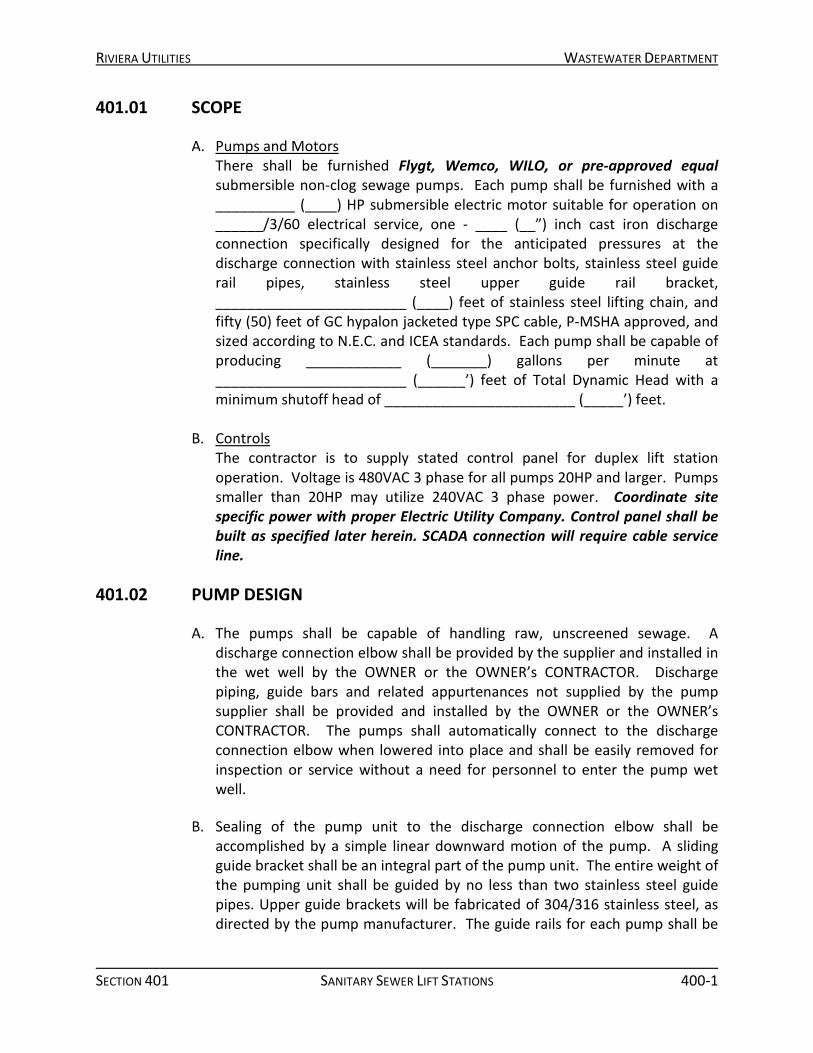
401.01 SCOPE
A. Pumps and Motors There shall be furnished Flygt, Wemco, WILO, or pre-approved equal submersible non-clog sewage pumps. Each pump shall be furnished with a __________ (____) HP submersible electric motor suitable for operation on ______/3/60 electrical service, one - ____ (__”) inch cast iron discharge connection specifically designed for the anticipated pressures at the discharge connection with stainless steel anchor bolts, stainless steel guide rail pipes, stainless steel upper guide rail bracket, ________________________ (____) feet of stainless steel lifting chain, and fifty (50) feet of GC hypalon jacketed type SPC cable, P-MSHA approved, and sized according to N.E.C. and ICEA standards. Each pump shall be capable of producing ____________ (_______) gallons per minute at ________________________ (______’) feet of Total Dynamic Head with a minimum shutoff head of ________________________ (_____’) feet.
B. Controls
The contractor is to supply stated control panel for duplex lift station operation. Voltage is 480VAC 3 phase for all pumps 20HP and larger. Pumps smaller than 20HP may utilize 240VAC 3 phase power. Coordinate site specific power with proper Electric Utility Company. Control panel shall be built as specified later herein. SCADA connection will require cable service line.
401.02 PUMP DESIGN
A. The pumps shall be capable of handling raw, unscreened sewage. A
discharge connection elbow shall be provided by the supplier and installed in the wet well by the OWNER or the OWNER’s CONTRACTOR. Discharge piping, guide bars and related appurtenances not supplied by the pump supplier shall be provided and installed by the OWNER or the OWNER’s CONTRACTOR. The pumps shall automatically connect to the discharge connection elbow when lowered into place and shall be easily removed for inspection or service without a need for personnel to enter the pump wet well.
B. Sealing of the pump unit to the discharge connection elbow shall be accomplished by a simple linear downward motion of the pump. A sliding guide bracket shall be an integral part of the pump unit. The entire weight of the pumping unit shall be guided by no less than two stainless steel guide pipes. Upper guide brackets will be fabricated of 304/316 stainless steel, as directed by the pump manufacturer. The guide rails for each pump shall be

RIVIERA UTILITIES WASTEWATER DEPARTMENT
SECTION 401 SANITARY SEWER LIFT STATIONS 400-2
standard weight 304/316 stainless steel. All fasteners are to be 316Ti. The guide system must not be required to support any portion of the weight of the pump. No portion of the pump or the guide support system, other than the discharge connection, shall be allowed to bear directly on the floor of the wet well. The pump, with its appurtenances and cable, shall be capable of continuous submergence underwater, without loss of watertight integrity, to a depth of sixty five (65) feet.
401.03 PUMP CONSTRUCTION
A. General 1. Major pump components shall be of gray cast iron, Class 35B, with
smooth surfaces devoid of blow holes and other irregularities. Where watertight sealing is required, O-rings made of nitrile rubber shall be used. All exposed nuts and bolts shall be stainless steel 316Ti construction. All surfaces, coming into contact with sewage, other than stainless steel, shall be protected by an approved sewage resistant coating. Pump exterior shall be sprayed with PVC epoxy primer, and a chloric rubber paint finish.
2. Each pump shall be provided with a tandem mechanical rotating shaft seal system. Seals shall run in an oil reservoir. Lapped seal faces must be hydrodynamically lubricated at a constant rate. The lower seal unit, between the pump and oil chamber, shall contain one stationary and one positively driven silicon carbide or tungsten carbide ring. The upper seal unit, between the oil sump and motor housing, shall contain one stationary silicon carbide or tungsten carbide ring and one positively driven rotating silicon carbide or tungsten carbide ring. Each interface shall be held in contact by its own spring system. The seals shall require neither maintenance nor adjustment but shall be easily inspected and replaceable.
3. All mating surfaces where watertight sealing is required shall be machined and fitted with nitrile rubber O-rings. Fittings will be such that sealing is accomplished by metal-to-metal contact between machined surfaces. This will result in controlled compression of the nitrile rubber O-rings without the requirement of a specific torque limit.
4. The cable entry shall be an integral part of the stator casing, and shall preclude specific torque requirements to insure a watertight and submersible seal. The cable entry shall be leak proof. Nicks or abrasions to motor connection cable should not result water wicking into the motor. The use of wire nuts or crimp-type connectors is not acceptable.
RIVIERA UTILITIES WASTEWATER DEPARTMENT
SECTION 401 SANITARY SEWER LIFT STATIONS 400-3
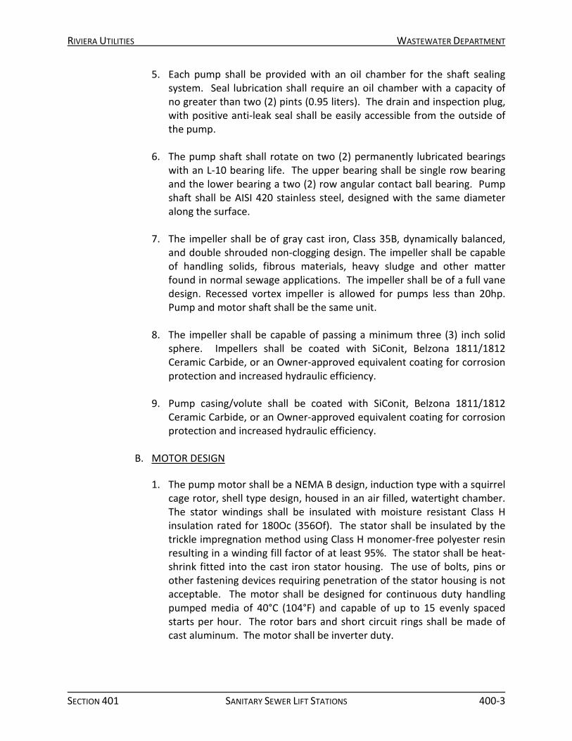
5. Each pump shall be provided with an oil chamber for the shaft sealing system. Seal lubrication shall require an oil chamber with a capacity of no greater than two (2) pints (0.95 liters). The drain and inspection plug, with positive anti-leak seal shall be easily accessible from the outside of the pump.
6. The pump shaft shall rotate on two (2) permanently lubricated bearings with an L-10 bearing life. The upper bearing shall be single row bearing and the lower bearing a two (2) row angular contact ball bearing. Pump shaft shall be AISI 420 stainless steel, designed with the same diameter along the surface.
7. The impeller shall be of gray cast iron, Class 35B, dynamically balanced, and double shrouded non-clogging design. The impeller shall be capable of handling solids, fibrous materials, heavy sludge and other matter found in normal sewage applications. The impeller shall be of a full vane design. Recessed vortex impeller is allowed for pumps less than 20hp. Pump and motor shaft shall be the same unit.
8. The impeller shall be capable of passing a minimum three (3) inch solid sphere. Impellers shall be coated with SiConit, Belzona 1811/1812 Ceramic Carbide, or an Owner-approved equivalent coating for corrosion protection and increased hydraulic efficiency.
9. Pump casing/volute shall be coated with SiConit, Belzona 1811/1812 Ceramic Carbide, or an Owner-approved equivalent coating for corrosion protection and increased hydraulic efficiency.
B. MOTOR DESIGN
1. The pump motor shall be a NEMA B design, induction type with a squirrel
cage rotor, shell type design, housed in an air filled, watertight chamber. The stator windings shall be insulated with moisture resistant Class H insulation rated for 180Oc (356Of). The stator shall be insulated by the trickle impregnation method using Class H monomer-free polyester resin resulting in a winding fill factor of at least 95%. The stator shall be heat-shrink fitted into the cast iron stator housing. The use of bolts, pins or other fastening devices requiring penetration of the stator housing is not acceptable. The motor shall be designed for continuous duty handling pumped media of 40°C (104°F) and capable of up to 15 evenly spaced starts per hour. The rotor bars and short circuit rings shall be made of cast aluminum. The motor shall be inverter duty.

RIVIERA UTILITIES WASTEWATER DEPARTMENT
SECTION 401 SANITARY SEWER LIFT STATIONS 400-4
2. Thermal switches set to open at 125°C (260°F) shall be embedded in the stator lead coils to monitor the temperature of each phase winding. These thermal switches shall be used in conjunction with and supplemental to external motor overload protection and shall be connected to the control panel. The control panel shall include the necessary circuitry to lock the pump(s) out if a high stator temperature is sensed. There shall also be seal fail moisture sensing probe to provide motor lockout and alarm light upon seal fail.
3. The combined service factor (combined effect of voltage, frequency and specific gravity) shall be a minimum of 1.15. The motor shall have a voltage tolerance of plus or minus 10%. The motor shall be designed for operation up to 40°C (104°F) ambient and with a temperature rise not to exceed 80°C. A performance chart shall be provided upon request showing curves for torque, current, power factor, input/output Kw and efficiency. This chart shall also include data on starting current and torque.
4. The motor horsepower shall be adequate so that the pump is non-overloading throughout the entire pump performance curve from shut-off through run-out.
401.04 SITE TEST
The pump shall be tested at start-up and voltage, current, and other significant parameters recorded. The manufacturer shall provide a formal test procedure and forms for recording data. Only factory certified service personnel shall perform start-up service. Proof of this certification will be required prior to equipment approval.
401.05 EXPERIENCE CLAUSE
A. Pumps The pump manufacturer shall have a minimum of one thousand (1,000) units of similar type pumps, installed and operating for no less than five (5) years in the United States.
B. Controls The controls supplier shall have a minimum of 200 units of similar type control panels, installed and operating for no less than five (5) years in the United States. All control panels are to be UL Listed. Contractor to supply reference list upon demand.
RIVIERA UTILITIES WASTEWATER DEPARTMENT
SECTION 401 SANITARY SEWER LIFT STATIONS 400-5
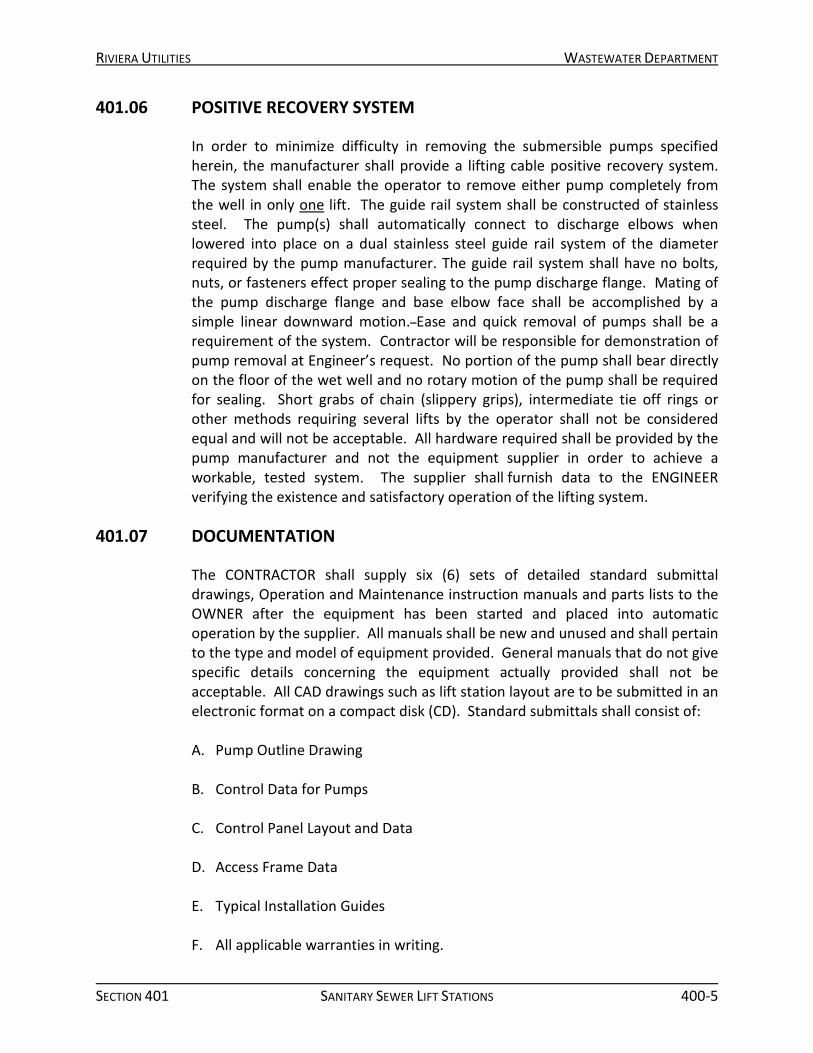
401.06 POSITIVE RECOVERY SYSTEM
In order to minimize difficulty in removing the submersible pumps specified herein, the manufacturer shall provide a lifting cable positive recovery system. The system shall enable the operator to remove either pump completely from the well in only one lift. The guide rail system shall be constructed of stainless steel. The pump(s) shall automatically connect to discharge elbows when lowered into place on a dual stainless steel guide rail system of the diameter required by the pump manufacturer. The guide rail system shall have no bolts, nuts, or fasteners effect proper sealing to the pump discharge flange. Mating of the pump discharge flange and base elbow face shall be accomplished by a simple linear downward motion. Ease and quick removal of pumps shall be a requirement of the system. Contractor will be responsible for demonstration of pump removal at Engineer’s request. No portion of the pump shall bear directly on the floor of the wet well and no rotary motion of the pump shall be required for sealing. Short grabs of chain (slippery grips), intermediate tie off rings or other methods requiring several lifts by the operator shall not be considered equal and will not be acceptable. All hardware required shall be provided by the pump manufacturer and not the equipment supplier in order to achieve a workable, tested system. The supplier shall furnish data to the ENGINEER verifying the existence and satisfactory operation of the lifting system.
401.07 DOCUMENTATION
The CONTRACTOR shall supply six (6) sets of detailed standard submittal drawings, Operation and Maintenance instruction manuals and parts lists to the OWNER after the equipment has been started and placed into automatic operation by the supplier. All manuals shall be new and unused and shall pertain to the type and model of equipment provided. General manuals that do not give specific details concerning the equipment actually provided shall not be acceptable. All CAD drawings such as lift station layout are to be submitted in an electronic format on a compact disk (CD). Standard submittals shall consist of:
A. Pump Outline Drawing
B. Control Data for Pumps
C. Control Panel Layout and Data
D. Access Frame Data
E. Typical Installation Guides
F. All applicable warranties in writing.
RIVIERA UTILITIES WASTEWATER DEPARTMENT
SECTION 401 SANITARY SEWER LIFT STATIONS 400-6
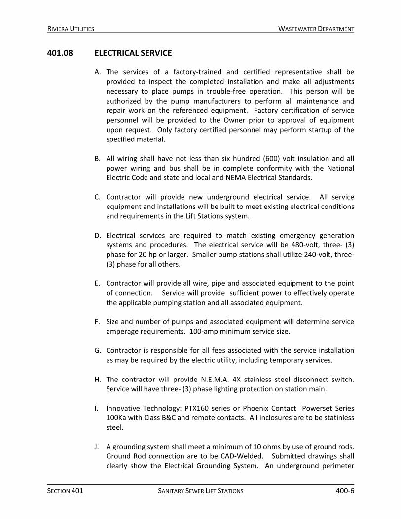
401.08 ELECTRICAL SERVICE
A. The services of a factory-trained and certified representative shall be provided to inspect the completed installation and make all adjustments necessary to place pumps in trouble-free operation. This person will be authorized by the pump manufacturers to perform all maintenance and repair work on the referenced equipment. Factory certification of service personnel will be provided to the Owner prior to approval of equipment upon request. Only factory certified personnel may perform startup of the specified material.
B. All wiring shall have not less than six hundred (600) volt insulation and all power wiring and bus shall be in complete conformity with the National Electric Code and state and local and NEMA Electrical Standards.
C. Contractor will provide new underground electrical service. All service equipment and installations will be built to meet existing electrical conditions and requirements in the Lift Stations system.
D. Electrical services are required to match existing emergency generation systems and procedures. The electrical service will be 480-volt, three- (3) phase for 20 hp or larger. Smaller pump stations shall utilize 240-volt, three- (3) phase for all others.
E. Contractor will provide all wire, pipe and associated equipment to the point
of connection. Service will provide sufficient power to effectively operate the applicable pumping station and all associated equipment.
F. Size and number of pumps and associated equipment will determine service
amperage requirements. 100-amp minimum service size.
G. Contractor is responsible for all fees associated with the service installation as may be required by the electric utility, including temporary services.
H. The contractor will provide N.E.M.A. 4X stainless steel disconnect switch.
Service will have three- (3) phase lighting protection on station main.
I. Innovative Technology: PTX160 series or Phoenix Contact Powerset Series 100Ka with Class B&C and remote contacts. All inclosures are to be statinless steel.
J. A grounding system shall meet a minimum of 10 ohms by use of ground rods. Ground Rod connection are to be CAD-Welded. Submitted drawings shall clearly show the Electrical Grounding System. An underground perimeter

RIVIERA UTILITIES WASTEWATER DEPARTMENT
SECTION 401 SANITARY SEWER LIFT STATIONS 400-7
cable grounding system shall be installed with connections to at least the following equipment: Wet Well Cover, Main Disconnect Switch, Fence, and Control Panel Mounting Rack. Bare copper wire (#4), to be connected to wet well cover and valve vault cover by way of approved mechanical connection. Under no circumstances shall (#4) wire be allowed to run across outside top slabs. The submitted drawings shall show details of material and installation to construct a completely functional and operational electrical grounding system.
401.09 ELECTRICAL CONSTRUCTION MATERIALS
A. Due considerations shall be given to the selection of materials because of the
presence of hydrogen sulfide and other corrosive gases, greases, oils, and other constituents frequently present in sewage. All mounting hardware will be type 316 stainless steel. (Nuts, bolts, washers, etc.). All enclosures and disconnects shall be type 304 stainless steel water tight N.E.M.A. 4X with gasket. All enclosures and disconnects shall be lockable with a padlock.
B. Pipe All exposed pipe shall be rigid galvanized steel pipe. All field cut steel pipe will have the threads cleaned and painted with cold galvanized paint. All steel pipe below grade will be painted with black asphalt paint, to a point of six inches (6”) above grade. This includes pipe form control panel to a point past first 90-degree ell fitting underground. PVC pipe form this point shall run to wet well to at least two inches (2”) inside well, with a PVC pipe end bell bushing in wet well. PVC shall be gray electrical type schedule 40. All exterior locknuts will be of the “Sealing” type on all equipment.
C. Electrical Connections Connections to motor leads and float control leads will be made outside the wet well. Conduit from wet well should terminate in air space below control panel. Penetrations into the enclosure shall be sealed tight with proper sealant to prevent moisture and gas from entering.
401.10 DISCHARGE PRESSURE MONITORING
An isolation ring shall be used in conjunction with a Pressure Transmitter. Signal cable shall connect to SCADA system for data collection. A. Isolation Ring: Red Valve Series 48W, or Ashcroft Type 80 Wafer, glycerin
filled, Buna N liner, 316L SS Flange and Body, ¼” NPT instrument connection, Needle Valve with Safe Quick Release instrument removal. Isolation ring shall be placed between two flanges on the discharge side of Tee, as shown on the plans.
RIVIERA UTILITIES WASTEWATER DEPARTMENT
SECTION 401 SANITARY SEWER LIFT STATIONS 400-8
B. Pressure Transmitter: Shall be 4-20Ma output, 0-100psig range, ¼”NPT male
connection, 0.25% accuracy. Contractor to extend cable to control panel. Any field splicing shall be soldered, heat shrink and sealed using best method to ensure sensor reliability and accuracy.
C. APPROVED MFG (See details 401.16 Approved Parts List) 1. ENDRESS HAUSER 2. PMP51-CD21JD1PGJRKJA1 3. RANGE: 0-100 PSI 4. OUTPUT: 4-20Ma HART
401.11 EQUIPMENT GUARANTEE
A. All equipment furnished for this project under these Specifications shall be
new and unused, and shall carry the full warranty for the manufacturer. The control system shall be warranted for one (1) year of acceptance by the OWNER. Material demonstrating defects in workmanship or materials will be repaired or replaced without cost or obligation to the OWNER.
B. All equipment furnished for this project under these Specifications shall be
new and unused, and shall carry the full warranty for the manufacturer. The pumps shall be covered under a five (5) year factory warranty, and the control system shall be warranted for one (1) year of acceptance by the OWNER. Material demonstrating defects in workmanship or materials will be repaired or replaced without cost or obligation to the OWNER.
401.12 SERVICE
A. The services of a factory trained and certified representative shall be
provided to inspect the completed installation and make all adjustments necessary to place controls in automatic trouble-free operation. This person will be authorized by the control manufacturers to perform all maintenance and repair work on the referenced equipment. Factory certification of service personnel will be provided to the Owner prior to approval of equipment upon request. Only factory certified personnel may perform startup of the specified material.
B. The services of a factory trained and certified representative shall be
provided to inspect the completed installation and make all adjustments necessary to place pumps in trouble-free operation. This person will be authorized by the pump manufacturers to perform all maintenance and repair work on the referenced equipment. Factory certification of service personnel will be provided to the Owner prior to approval of equipment

RIVIERA UTILITIES WASTEWATER DEPARTMENT
SECTION 401 SANITARY SEWER LIFT STATIONS 400-9
upon request. Only factory certified personnel may perform startup of the specified material.
401.13 ALTERNATE EQUIPMENT SUBMITTAL
The OWNER is prepared to compare and evaluate similar equipment that may not meet all requirements of the specifications. However, in order to evaluate alternates, the supplier of alternate equipment may be required to justify in terms of equipment longevity, ease of maintenance or cost of replaceable parts to the satisfaction of the OWNER choosing equipment other than as specified. The OWNER reserves the right to weigh any differences in price to the equipment specified and choose alternate equipment based on the above referenced justification.
401.14 PUMP STATION CONTROL PANELS
A. General
1. Section Details
This section includes all elements required to furnish and install a complete electrical control system to control, operate, and display information as indicated in the plans and specifications. The control system shall include all equipment, devices, wiring, and incidental materials to operate the system and display or relay information in accordance with these specifications. The intention of this section is to secure a complete control system that will operate equipment in accordance with narratives and requirements indicated in the plans, specifications, and manufacturer’s literature for the equipment installed. All circuits and devices for protection of installed equipment shall be included in the lump sum bid.
2. Scope of Work
The contractor shall furnish and install with each pump station, one EcoSmart Station® control panel. The pump station control panel shall house the complete electrical system to operate the pump station. The control panel shall be manufactured by a UL certified panel facility and shall meet all UL698A standards (Industrial control equipment with circuit extensions into hazardous locations). All components shall be UL recognized or listed including those supplied by the pump manufacturer and the control panel shall house all necessary controls including circuit breakers, VFD’s, and other equipment specified herein. The panel shall be built to meet NEMA Type 4X ratings (Controls compartment), NEMA Type 3R ratings (Service and MCC compartments), and shall in all respects conform to the National Electric Code and all other state and

RIVIERA UTILITIES WASTEWATER DEPARTMENT
SECTION 401 SANITARY SEWER LIFT STATIONS 400-10
local codes which may apply. Manufacturer shall be Primex Controls or Owner Approved Equal.
3. Definitions
a. AIC – Amps Interrupting Current is the maximum current that is produced upon a fault to ground or a fault between phases.
b. Arc Flash – An electrical explosion that can occur when there is an
uncontrolled conduction of electrical current to ground or to another phase. An Arc Flash occurs very rapidly and produces intense heat and energy that can harm personnel and destroy equipment.
c. Control Compartment – A compartment in the EcoSmart Station® that contains all control components of the pump station including the EnergyView® controller, communications and other devices.
d. ECO Mode – An operation mode that operates the pumps at a speed
determined by auto efficiency tuning of the EnergyView® controller.
e. FLA – Full Load Amps f. GFCI – Ground Fault Circuit Interrupter g. GPM – Gallons Per Minute h. HMI – Human Machine Interface i. HOA – Hand-Off-Auto operator switch j. Kw – Kilowatts (power) k. MCC – Motor Control Center l. MCC Compartment – A compartment in the EcoSmart Station® that
contains components related to motor starting. Some components include variable frequency drives, pump breakers, the control power transformer, and the voltage monitor.
m. Service Compartment – A compartment in the EcoSmart Station® that
contains service entrance equipment for the station. Some components include main incoming terminal blocks, main service circuit breaker, phase monitor and other protective devices, and a transfer switch with generator receptacle (if required).
RIVIERA UTILITIES WASTEWATER DEPARTMENT
SECTION 401 SANITARY SEWER LIFT STATIONS 400-11
n. PID – Proportional Integral and Derivative o. PID Mode – A mode in the EnergyView® controller that keeps a
constant wet well level by varying the pump speed. p. PLC – Program Logic Controller
q. Skirt Compartment – A vented compartment under the EcoSmart
Station® that is reserved for routing of cables into various compartments.
r. UPS – Uninterruptable Power Supply s. VFD – Variable Frequency Drive
4. References
a. ANSI®/NFPA® 70 – National Electrical Code® (NEC®) b. IEC 61000 – Electromagnetic Compatibility c. NEMA 250 – Enclosures for Electrical Equipment d. NEMA ICS7 – Industrial Control and Systems Adjustable Speed Drives e. UL® 50 – Enclosures for Electrical Equipment f. UL 98 – Disconnect Switches g. UL 507 – Electric Fans h. UL 508 – Industrial Control Equipment i. UL 508C – Power Conversion Equipment j. UL 698A – Circuit extension into hazardous locations k. UL 991 – Safety Tests l. IEEE-519 – Harmonic levels m. NFPA 70E – National Fire Protection Association

RIVIERA UTILITIES WASTEWATER DEPARTMENT
SECTION 401 SANITARY SEWER LIFT STATIONS 400-12
5. Submittals The Engineer reserves the right to approve or disapprove any and all equipment based upon evaluation. Approval for fabrication and installation will be made only after submittal and review of all shop contract documents. The information required for approval shall include the following items and be provided to the engineer prior to the bid date.
a. Electrical schematics
b. Enclosure dimensional drawings
c. Complete layout drawing with dimensions
d. Heat loss calculation in MCC compartment
e. Manufacturer data sheet for all components
f. Complete bill of material
g. User operating manual
h. Installation instructions
i. 2 year warranty certificate
6. Substitutions
The Engineer will consider proposals for substitution of materials, equipment, methods and services only when proposals are accompanied by full and technical data and all other information required by the Engineer for the proposed substitution. Substitution of materials, equipment, methods and/or services is not allowed unless such substitution has been specifically approved by the Engineer and Utility.
7. Quality Assurance
a. Enclosure
i. The enclosure shall be fabricated under the regulations of ISO 9001 certification for the manufacturing of enclosures.
ii. The enclosure shall be a UL508 listed enclosure.
RIVIERA UTILITIES WASTEWATER DEPARTMENT
SECTION 401 SANITARY SEWER LIFT STATIONS 400-13
b. Control Panel
i. Control panel shall be manufactured in a UL508A facility and be UL certified to manufacture panels with UL698A intrinsically safe components.
ii. Factory shall conduct full operational tests with appropriate
voltage applied to the panel.
8. Delivery, Handling, and Storage All materials relating to this section individually and as completed panels shall be handled as fragile equipment and stored only inside closed buildings and protected from moisture entry. All openings shall be continuously sealed until the moment that connections thereto are actually made.
9. Warranty
a. 24 Months from date of manufacture. b. The warranty shall apply to being free to defects in material and
workmanship.
B. Products 1. Enclosure
a. The enclosure shall be one freestanding enclosure consisting of four different compartments within one footprint. The entire panel enclosure shall be fabricated with stainless steel type 304 powder coated white. Approved Enclosure shall be Arc Armor® by PRIMEX, an SJE Rhombus master brand.
b. Alternate Control Panel Enclosures
i. Alternate control panel equipment shall include a complete
control panel design stamped by a Professional Engineer registered in the state of Alabama. The design and operation shall meet or exceed the minimum requirements and include the components as specified herein.
ii. Provide an arc flash study report. The report should include modeling, analysis drawing, fault current and coordination analysis, Personal Protective Equipment (PPE) level
RIVIERA UTILITIES WASTEWATER DEPARTMENT
SECTION 401 SANITARY SEWER LIFT STATIONS 400-14
recommendations, arc flash equipment labeling, notes and recommendations for areas presenting risk to personnel or equipment.
2. Compartment Requirements
a. The Service compartment shall be a NEMA Type 3R rated compartment that houses the main service power components.
b. The MCC compartment shall be NEMA Type 3R rated compartment that houses the motor starter components.
c. The Control compartment shall be NEMA Type 4X rated compartment
the houses all controls associated with the panel. The maximum voltage within this compartment is to be maximum of 30vac.
d. The Skirt compartment is a nonrated vented compartment that
provides an area for the entry of well conduits. All conduits with the exception of line power will come through the Skirt compartment.
e. Conduit and mounting template – A drawing shall be provided with
each enclosure to provide anchoring locations and conduit locations entering the enclosure. This drawing shall be available at the time of conduit and foundation layout.
f. Cable entrance into the control panel from the Skirt area shall utilize
Myers hubs in conjunction with cord grips. 3. Enclosure Construction
a. All compartments are fabricated as one complete unit with singular common separation walls resulting in one complete enclosure. The NEMA Type rating integrity of each compartment shall be maintained at all times from the factory manufactured enclosure through final installation.
b. Interior wall construction: all common walls shall consist of one sheet of type 304L (18-8) stainless steel with a minimum 14-gauge thickness (0.075 inches). Backs to back or double walls are not acceptable.
c. Interior mounting: all mounting plates, hinges and other components mounted onto the enclosure walls shall be held in place by welded in place stainless studs. There shall be no penetrations for through

RIVIERA UTILITIES WASTEWATER DEPARTMENT
SECTION 401 SANITARY SEWER LIFT STATIONS 400-15
bolts or other means of anchoring into the compartments from the exterior of the cabinet.
d. The exterior and interior finish of the panel shall be powder coat 3-4 mil minimum polyester power coat finish. The enclosure shall be prepped by an acid wash prior to an electro-statically precipitated applied paint that should be baked at a high temperature to bond paint to enclosure surface. Powder coating shall be performed after final enclosure assembly and prior to mounting electrical devices and components. All surfaces shall be painted on both sides and on edges.
e. Exterior door handles to be die-cast aluminum alloy powder coated
black. Door handles to be fully lockable and able to accommodate a #21 Master padlock. Each door handle must be NEMA Type rated to maintain the rating of the associated compartment.
f. Exterior door hinges shall be continuous 304L stainless steel piano
type hinges. All hinges are finished with white powder coating.
g. Mechanical door stops to be mounted on the Control and MCC compartment doors to secure the door in the open position at 110 degrees. Door may be closed by manually lifting up on the door stop arm. They shall be located at the bottom of each cabinet door.
h. A grey thermoplastic data pocket is to be mounted on the door of the MCC compartment.
i. Two lifting eyebolt rings shall be installed on the top center of the panel and penetrate through the top of the panel. The lifting eyebolt rings shall enter into the MCC compartment, not the Control compartment. Each individual lifting eyebolt ring shall be rated the entire weight of the panel. The top drip cap shall be structurally reinforced for the lifting load at the point of attachment of the eyebolt rings. The lifting eyebolt ring shall have a gasket to prevent water entry into the MCC compartment. Lifting eyebolt ring shall be oriented in parallel to the width of the enclosure. They shall be constructed from high tensile strength steel, powder coated white.
j. A drip cap shall be installed as one continuous sheet of stainless steel covering the entire top of the Arc Armor® enclosure. The drip cap shall have rolled edge with a 1” trough continuous to each end. It shall be constructed of a minimum 14 gauge stainless steel with a white powder coat finish.

RIVIERA UTILITIES WASTEWATER DEPARTMENT
SECTION 401 SANITARY SEWER LIFT STATIONS 400-16
k. The Control compartment shall have a dead front inner door for mounting the controller, indicators, and switches. The inner door shall be constructed out of .125” aluminum. The door shall be mounted to the enclosure via a continuous piano hinge. Two twist lock latches are to be used to secure the inner door in the closed position. The latches are to be T-handle type constructed from polyamide-6 nylon plastic 30% glass reinforced material. They shall be mountable through square holes to prevent rotation of the entire mechanism.
4. General Enclosure Requirements
a. The reduction of the Arc Flash potential shall be reduced by isolating high voltage into specific compartments.
b. The Service and MCC compartments may contain components that
operate at a voltage that is capable of creating an Arc Flash condition. Personnel Protection Equipment (PPE) is required. Accessibility should be limited to qualified electricians only.
c. The Control compartment only contains control voltage (maximum of
30vac). Minimal Personnel Protection Equipment (PPE) is required for operators and maintenance personnel. See NFPA 70E for proper PPE requirements.
d. All penetrations through compartments shall be performed to
maintain the NEMA Type ratings of each individual compartment. e. The enclosure shall be constructed so that no screws or bolt heads
are visible when viewed from any external portion of the enclosure. f. Punch cutouts for instruments and other devices shall be cut,
punched, or drilled and smoothly finished with rounded edges. g. No holes shall be drilled in the top (rain cap) of the cabinet (with the
exception of the lifting eyebolts). h. Electrical schematic shall be permanently affixed to inside of the
outer door of the Control and MCC compartments. The schematic shall resist water to prevent removal and discoloration from heat, gasses, and ultraviolet light.
RIVIERA UTILITIES WASTEWATER DEPARTMENT
SECTION 401 SANITARY SEWER LIFT STATIONS 400-17
5. Service Compartment Component and Requirements
a. Service Entrance Termination The main service entrance conductors shall be terminated onto lugs
mounted at the bottom center of the Service compartment. The lugs shall be aluminum compression type and shall be rated for both aluminum and copper wire terminations. The lugs shall be sized to accommodate the wire size of service entrance conductors. Component shall be Square D, 9080 series.
b. Main Circuit Breaker The main circuit breaker shall be a thermal-magnetic molded case
circuit breaker rated to 600V and sized according to the NEC and the load requirements of the control panel. It shall be mounted in the compartment with a lockable handle mechanism mounted on the Service compartment door. Component shall be Square D, HDL Type. For 400A use type LAL.
c. Surge Suppressor A surge suppressor shall be connected to the load side of the main
service circuit breaker. It shall be mounted behind a protective cover on which the main service entrance termination lugs are mounted. Components shall be Surge Suppression Inc. SKLA3N4.
d. Control Transformer Primary Circuit Breaker
The control power circuit breaker shall be sized according to the rating of the primary windings of the control power transformer. The line side of the circuit breaker shall be supplied from a tap from the load side of the main circuit breaker. Component shall be Schneider Electric, HDL series.
e. Generator Receptacle Optional generator receptacle shall be mounted on the side of the
Service compartment for control panels equipped with manual transfer switch. The receptacle shall be of reverse service configurations to avoid exposure to live parts when the mating plug is energized. Component shall be manufactured by Appleton Reverse Service and/or match existing site generator plug style.
f. Generator Main Circuit Breaker If a generator receptacle is installed, it is to have a designated Main
Circuit Breaker that is mechanically interlocked with the Line Main Circuit Breaker. The mechanical interlock must prevent both breakers from being in the ON position at the same time. The generator main

RIVIERA UTILITIES WASTEWATER DEPARTMENT
SECTION 401 SANITARY SEWER LIFT STATIONS 400-18
circuit breaker shall be a thermal-magnetic molded case circuit breaker rated to 600v and sized according to the NEC and the load requirements of the control panel. It shall be mounted in the compartment with a lockable handle mechanism mounted on the Service compartment door. Component shall be Square D, HDL Type. For 400A use type LAL.
6. MCC Compartment Component Requirements
a. Three Phase Voltage Indicator A voltage indicator shall be mounted on the door of the MCC compartment to provide a warning that high energy circuits are energized and voltage is present on each phase. The voltage indicator warns against the potential danger of electric shock, Arc Flash and/or Arc Blast conditions inside the cabinet. Component shall be Diversified Electronics, Model UPA-100.
b. Door Interlock An electromechanical door interlock shall prevent access into the MCC compartment unless the main power is disconnected. The MCC compartment door interlock mechanism is powered through a two-pole circuit breaker in the MCC compartment. Component shall be Hoffman, Model AEK460NDH-460.
c. Pump Circuit Breakers Pump circuit breakers to be a thermal-magnetic molded case breaker. Individual pump circuit breaker shall be sized according to the Motor Starter manufacturer, NEC and the FLA of the pump. Components shall be Schneider Electric, HDL type.
d. Door Interlock Circuit Breaker MCC compartment door interlock circuit breaker shall be a two-pole 10-amp circuit breaker and supplied from a tap from the load side of the main circuit breaker. It shall be DIN rail mount. Component shall be Schneider Electric, MGN series.
e. Control Power Transformer A control power transformer is only required on stations that do not provide 120 volts to a service neutral. Component shall be Schneider Electric, Model 9070T2000D1.
f. Phase Monitor The phase loss monitor shall be supplied from the load side of the main disconnect. It shall monitor the voltage of each phase and

RIVIERA UTILITIES WASTEWATER DEPARTMENT
SECTION 401 SANITARY SEWER LIFT STATIONS 400-19
provide a dry contact closure upon phase loss, phase reversal, overvoltage or under voltage condition. Monitor shall have an adjustable reset delay. Component shall be Macromatic PMPU.
g. Motor Starters At all locations which require pump motors to be sized 20 hp or larger., a “VFD Variable Frequency Drive” as manufactured by Yaskawa (20 hp and larger) P1000 with analog inputs, will be provided for each pump to ramp up to start speed and down to stop. VFD shall have the following options: RS485 Modbus Communication and a 4 to 20ma input for speed control signal supplied by the PLC. VFD system is to comply with IEEE 519 harmonics mitigation standard.
i. Pump sizes of 15HP up to 20 HP will utilize Magnetek RVS-DX Soft
starters with RS485 option.
ii. All others will be started Across the Line with Square- D Nema Style motor starters with solid state overload relay. Coil on Across the line starters are to be fitted with arc transient suppression.
h. Cooling Fans (ONLY REQUIRED WHEN USING VFD’S)
The MCC compartment shall have two ventilation fans when VFD’s are required. One fan shall be located at the air intake shroud in the bottom right side of the compartment, supplying air into the compartment. A second fan shall be located at the exhaust shroud, located in the upper left side of the compartment and exhausting air outside. Both fans shall 120VAC supplied from 3-amp circuit breaker and be thermostatically controlled. Each fan shall have filter and finger guards. Components shall be Sunon, P/N-SP100A.
i. Thermostat (ONLY REQUIRED WHEN USING VFD’S) A thermostat shall be mounted in the MCC compartment and operate the fans on rising internal temperature. The thermostat shall be mounted in the lower half of the MCC compartment in order to avoid short cycling. The thermostat shall control the operation of both fans in parallel. Component shall be Pfannenberg, P/N-17121000010.
j. Condensation Heater Minimum 100W with thermostat as Manufactured by Hoffman, model DAH1001A.

RIVIERA UTILITIES WASTEWATER DEPARTMENT
SECTION 401 SANITARY SEWER LIFT STATIONS 400-20
k. Compartment Service Light The MCC compartment shall have an LED service light installed in the upper front portion of the compartment. The service light shall be operated by an ON/OFF switch located on the inner door of the controls compartment. It shall operate at 24VDC and be supplied from the battery backup in order for the light to operate during a power loss. Component shall be Super Bright LEDs, LF-CW30SMD.
l. Pump Terminal Blocks The terminal blocks for motor lead terminations shall be mounted on an angled and raised bracket to provide easy access for field wiring terminations. Components shall be by Square D, (size will very on pump size).
m. MCC/Control Compartment Interconnecting Seal Barrier A cable barrier shall be installed that provides isolation between the MCC compartment and the Control compartment. The barrier shall be used to maintain a NEMA Type 3R rating in the MCC compartment and a NEMA Type 4X rating in the Control compartment. All control cables shall pass through the barrier.
n. Power Supply, 24V, Automation Direct Model PSM24-180S o. Surge Suppressors
i. SPD120V Surge Suppressor Inc. Model S-SPT120-30 ii. SPD 24Vdc Surge Suppressor Inc. Model TC24D2-B iii. SPD 24V Current Loop Surge Suppressor Model CLC24A2-B
p. Control Circuit Breakers Control Circuit Breakers as required shall be Square D 600000 Series.
7. Controls Compartment Requirements
a. PLC Controller
i. Controller shall be complete, programmed and tested prior to shipment.
ii. The display unit shall have the following features:
• 12” color, touch screen HMI. • The I/O module shall have the following features: • 32 Discrete DC inputs, 32 Discrete DC outputs • Analog inputs, 2 analog outputs
RIVIERA UTILITIES WASTEWATER DEPARTMENT
SECTION 401 SANITARY SEWER LIFT STATIONS 400-21
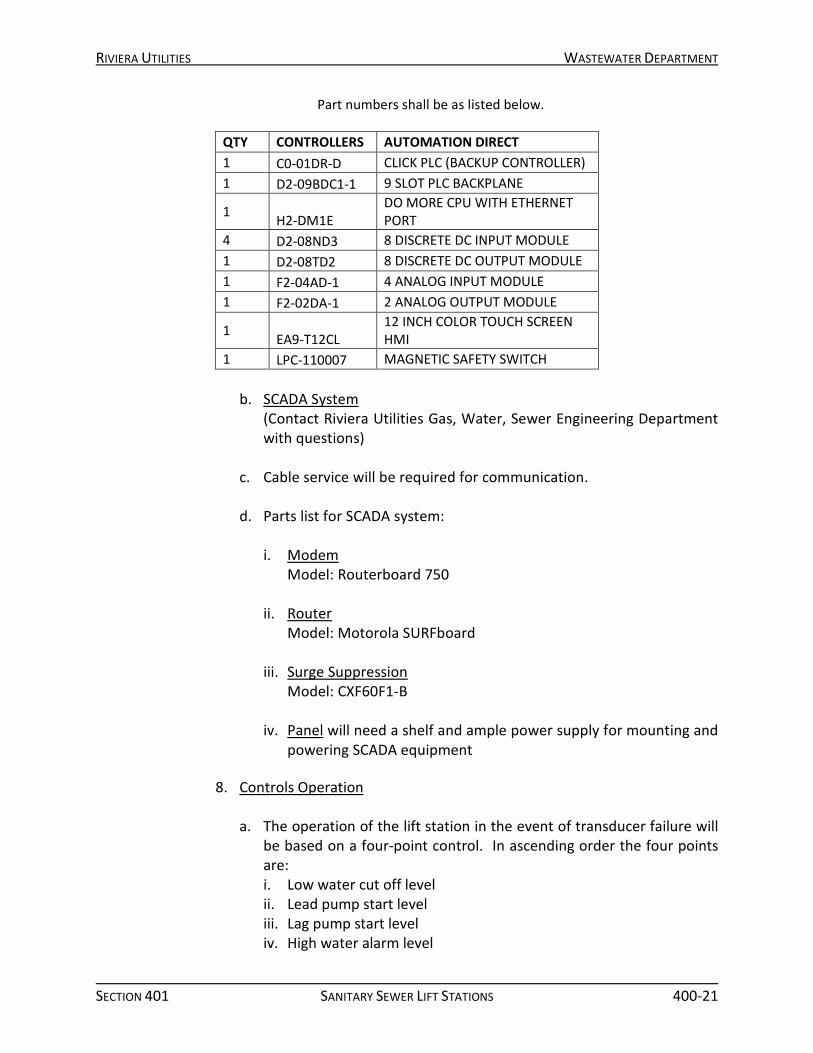
Part numbers shall be as listed below.
QTY CONTROLLERS AUTOMATION DIRECT 1 C0-01DR-D CLICK PLC (BACKUP CONTROLLER) 1 D2-09BDC1-1 9 SLOT PLC BACKPLANE
1 H2-DM1E DO MORE CPU WITH ETHERNET PORT
4 D2-08ND3 8 DISCRETE DC INPUT MODULE 1 D2-08TD2 8 DISCRETE DC OUTPUT MODULE 1 F2-04AD-1 4 ANALOG INPUT MODULE 1 F2-02DA-1 2 ANALOG OUTPUT MODULE
1 EA9-T12CL 12 INCH COLOR TOUCH SCREEN HMI
1 LPC-110007 MAGNETIC SAFETY SWITCH b. SCADA System
(Contact Riviera Utilities Gas, Water, Sewer Engineering Department with questions)
c. Cable service will be required for communication. d. Parts list for SCADA system:
i. Modem
Model: Routerboard 750 ii. Router
Model: Motorola SURFboard iii. Surge Suppression
Model: CXF60F1-B
iv. Panel will need a shelf and ample power supply for mounting and powering SCADA equipment
8. Controls Operation
a. The operation of the lift station in the event of transducer failure will
be based on a four-point control. In ascending order the four points are: i. Low water cut off level ii. Lead pump start level iii. Lag pump start level iv. High water alarm level
RIVIERA UTILITIES WASTEWATER DEPARTMENT
SECTION 401 SANITARY SEWER LIFT STATIONS 400-22
v. The lead pump is energized when the sewage level reaches the “lead pump start point”. The lead pump shall operate continuously until the water level is lowered to the “low water cut-off point”. The lag pump shall be energized if the lead pump is incapable of handling the flow of sewage, allowing the water level to reach the “lag pump start point.” The lag pump shall then operate in unison with the lead pump until the water level is lowered to the “low water cut off point.” At this time, both pumps are de-energized. Provide time delay relay to prevent both lead and lag pumps from starting at the same time. Provide total number of starts per hour based on pump motor limits.
b. An automatic circuit (PLC) will define process settings by using a operator interface. The following features will be provided by the operator interface: i. Transducer or Float Control user selection ii. Wet Well Level iii. Wet Well Set point iv. Thermal Fault Pump 1 v. Thermal Fault Pump 2 vi. Moisture Fault Pump 1 vii. Moisture Fault Pump 2 viii. Reset Moisture Fault Pump 1 ix. Reset Moisture Fault Pump 2 x. Reset High Level Alarm xi. Backup Pump failure xii. Primary Pump failure xiii. Float Failure xiv. Transducer Failure xv. Surge Suppressor Failure xvi. Power Supply Failure xvii. VFD failure xviii. VFD remote xix. Silence High Level Alarm to Station Light
C. Execution
All work shall be done in accordance with appropriate Divisions and Section and shall be performed in a workmanship manner.
1. Fabrication
a. All control panels shall be shop assembled and factory tested prior to
delivery to the site. Final as-built drawing shall be made to reflect all
RIVIERA UTILITIES WASTEWATER DEPARTMENT
SECTION 401 SANITARY SEWER LIFT STATIONS 400-23
adjustments and modifications made to the system after start-up has been completed satisfactorily. All equipment and devices shall be mounted, adjusted, calibrated, and operated exactly as recommended by the manufacturer of each component.
b. Control switches, indicator lights, and other devices shall be grouped as stated in this section and in submittal package.
2. Equipment Installation
All equipment shall be installed in accordance with approved drawings and the manufacturer’s written instructions.
3. Wiring and Terminations
a. All wiring shall follow NEC color coding scheme.
b. All wiring shall be run parallel to side walls of panels and/or in
covered wiring troughs. Wires passing across hinged areas shall be protected by abrasion resistant cabling materials.
4. Identification
All conductors shall be labeled at each end with numbers matching submittals data sheets and all wire terminations shall be identified by the component terminal numbers as shown on appropriate panel drawings.
5. Start-Up
a. Startup shall be done in accordance with manufacturer’s written
instructions and be completed by qualified electrician or a PRIMEX Authorized Engineered Distributor.
b. A completed start up report shall be returned to PRIMEX in order to maintain full warranty coverage.
401.15 PUMP STATION BASIN CONFIGURATION
A. Fiberglass Wetwell or Lift Station
1. General Fiberglass reinforced polyester wet wells shall be manufactured from commercial grade polyester resin or vinyl ester resin, with fiberglass reinforcements. The resin system shall be suitable for atmospheres containing hydrogen sulfide and dilute sulfuric acid as well as other gases

RIVIERA UTILITIES WASTEWATER DEPARTMENT
SECTION 401 SANITARY SEWER LIFT STATIONS 400-24
associated with the wastewater collection systems. The wet well shall be a one-piece unit manufactured by L. F. Manufacturing, Inc., Giddings, Texas, 1-800-237-5791 or an approved equal.
2. Materials
a. Resin
The resins used shall be a commercial grade unsaturated polyester resin.
b. Reinforcing Materials The reinforcing materials shall be commercial Grade “E” type glass in the form of mat, continuous roving, chopped roving, roving fabric or a combination of the above, having a coupling agent that will provide a suitable bond between the glass reinforcement and the resin.
c. Surfacing Material If reinforcing materials are used on the surface exposed to the contained substance, it shall be a commercial grade chemical-resistant glass that will provide a suitable bond with the resin and leave a resin rich surface.
d. Fillers and Additives Fillers, when used, shall be inert to the environment and wet well construction. Additives, such as thixotropic agents, catalysts, promoters, etc., may be added as required by the specific manufacturing process to be used. The resulting reinforced plastic material must meet the requirement of this specification.
3. Fabrication
a. Exterior Surface
The exterior surface shall be relatively smooth with no sharp projections. Handwork finish is acceptable if enough resin is present to eliminate fiber show. The exterior surface shall be free of blisters larger than ½ inch in diameter, delamination and fiber show. For a UV inhibitor the resin on the exterior surface of the manhole shall have gray pigment added for a minimum thickness .125 inches.
b. Interior Surface The interior surface shall be resin rich with no exposed fibers. The surface shall be free of grazing, delamination, and blisters larger than ½ inch in diameter, and wrinkles of 1/8 inch or greater in

RIVIERA UTILITIES WASTEWATER DEPARTMENT
SECTION 401 SANITARY SEWER LIFT STATIONS 400-25
depth. Surface pits shall be permitted up to 6 square feet if they are less than ¾ inch in diameter and less than 1/16 inch deep.
c. Fiberglass Reinforced Bottom The bottom to be fabricated using fiberglass material as stated in section A.2. Material and installation to meet all physical requirements as per section A.4. Bottom to be attached to wet well pipe with fiberglass layup to comply with A.S.T.M.-D3299 specifications. When reinforcement is necessary for strength, the reinforcement shall be fiberglass channel laminated to wet well bottom per A.S.T.M.-D3299.
d. Integral Internal Fiberglass Fillet Fiberglass wet wells and basins may have an internal sloped fillet bottom. The fillet shall be constructed of the same fiberglass material as the wet well or basin and shall be integral to the wet well or basin. The fiberglass fillet shall have a 1:1 slope and shall not interfere with pump mounting in the wet well or basin.
e. Fiberglass Reinforced Top The fiberglass wet well top shall be fabricated using fiberglass material as stated in section A.2. Material and installation to meet all physical requirements as per section A.4. Top to be attached to wet well pipe with fiberglass layup to comply with A.S.T.M.-D3299 specifications. When reinforcement is necessary for strength, the reinforcement shall be fiberglass channel laminated to wet well bottom per A.S.T.M.-D3299.
f. Installation Of Stub-Outs Effluent, service, or discharge lines may be factory installed. Approved methods are PVC sewer pipe, Inserta-Tee fittings, or Kor-N-Seal boots. Installation of stubouts to be fiberglass layup to comply with A.S.T.M.-D3299 specifications.
g. Defects Not Permitted i. Exposed Fibers
Glass fibers not wet out with resin.
ii. Resin Runs Runs of resin and sand on the surface.
iii. Dry Areas Areas with glass not wet out with resin.
RIVIERA UTILITIES WASTEWATER DEPARTMENT
SECTION 401 SANITARY SEWER LIFT STATIONS 400-26
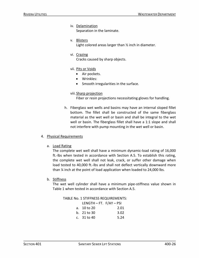
iv. Delamination Separation in the laminate.
v. Blisters Light colored areas larger than ½ inch in diameter.
vi. Crazing Cracks caused by sharp objects.
vii. Pits or Voids • Air pockets. • Wrinkles: • Smooth irregularities in the surface.
viii. Sharp projection
Fiber or resin projections necessitating gloves for handling.
h. Fiberglass wet wells and basins may have an internal sloped fillet bottom. The fillet shall be constructed of the same fiberglass material as the wet well or basin and shall be integral to the wet well or basin. The fiberglass fillet shall have a 1:1 slope and shall not interfere with pump mounting in the wet well or basin.
4. Physical Requirements
a. Load Rating
The complete wet well shall have a minimum dynamic-load rating of 16,000 ft.-lbs when tested in accordance with Section A.5. To establish this rating, the complete wet well shall not leak, crack, or suffer other damage when load tested to 40,000 ft.-lbs and shall not deflect vertically downward more than ¼ inch at the point of load application when loaded to 24,000 lbs.
b. Stiffness The wet well cylinder shall have a minimum pipe-stiffness value shown in Table 1 when tested in accordance with Section A.5.
TABLE No. 1 STIFFNESS REQUIREMENTS:
LENGTH – FT. F/AY – PSI a. 10 to 20 2.01 b. 21 to 30 3.02 c. 31 to 40 5.24
RIVIERA UTILITIES WASTEWATER DEPARTMENT
SECTION 401 SANITARY SEWER LIFT STATIONS 400-27
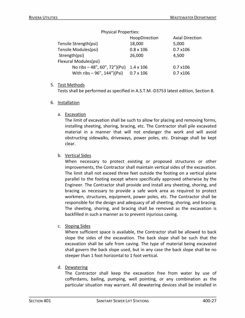
Physical Properties: HoopDirection Axial Direction Tensile Strength(psi) 18,000 5,000 Tensile Modules(psi) 0.8 x 10⁶ 0.7 x10⁶ Strength(psi) 26,000 4,500 Flexural Modules(psi) No ribs – 48”, 60”, 72”)(Psi) 1.4 x 10⁶ 0.7 x10⁶ With ribs – 96”, 144”)(Psi) 0.7 x 10⁶ 0.7 x10⁶
5. Test Methods Tests shall be performed as specified in A.S.T.M.-D3753 latest edition, Section 8.
6. Installation
a. Excavation
The limit of excavation shall be such to allow for placing and removing forms, installing sheeting, shoring, bracing, etc. The Contractor shall pile excavated material in a manner that will not endanger the work and will avoid obstructing sidewalks, driveways, power poles, etc. Drainage shall be kept clear.
b. Vertical Sides When necessary to protect existing or proposed structures or other improvements, the Contractor shall maintain vertical sides of the excavation. The limit shall not exceed three feet outside the footing on a vertical plane parallel to the footing except where specifically approved otherwise by the Engineer. The Contractor shall provide and install any sheeting, shoring, and bracing as necessary to provide a safe work area as required to protect workmen, structures, equipment, power poles, etc. The Contractor shall be responsible for the design and adequacy of all sheeting, shoring, and bracing. The sheeting, shoring, and bracing shall be removed as the excavation is backfilled in such a manner as to prevent injurious caving.
c. Sloping Sides Where sufficient space is available, the Contractor shall be allowed to back slope the sides of the excavation. The back slope shall be such that the excavation shall be safe from caving. The type of material being excavated shall govern the back slope used, but in any case the back slope shall be no steeper than 1 foot horizontal to 1 foot vertical.
d. Dewatering The Contractor shall keep the excavation free from water by use of cofferdams, bailing, pumping, well pointing, or any combination as the particular situation may warrant. All dewatering devices shall be installed in

RIVIERA UTILITIES WASTEWATER DEPARTMENT
SECTION 401 SANITARY SEWER LIFT STATIONS 400-28
such a manner as to provide clearance for construction, removal of forms, and inspection of exterior of form work. It is the intent of these specifications that the foundation be placed on a firm dry bed. The foundation bed shall be kept in a dewatered condition a sufficient period of time to insure the safety of the structure. All dewatering methods and procedures are subject to the approval of the Engineer. The excavation shall be protected from excessive rainfall, drainage and drying. The excavation shall be inspected and approved by the Engineer before work on the structure is started. It is the intent of these specifications that the Contractor provide a relatively smooth, firm foundation bed for footings and slabs that bear directly on the undisturbed earth without additional cost to the Owner, regardless of the soil conditions encountered. The Engineer will be the sole judge as to whether these conditions have been met. The contractor shall pile excavated material in a manner that will not endanger the work.
e. Unauthorized Over Excavation Excavation for slabs, footings, etc., that bear on earth shall not be carried below the elevation shown on the drawings. In the event the excavation is carried on below the indicated elevation, the Contractor shall bring the slab, footing, etc., to the required grade by filling with concrete having a minimum compressive strength of at least 3,000 psi at 28 days.
f. Handling Do not drop or impact the wet well. Wet wells shall be chocked if stored horizontally. If wet wells must be moved by rolling, the ground transverse shall be smooth and free of rocks, debris, etc. FRP wet wells may be lifted by the installation of two lifting lugs as specified by the manufacturer on the outside surface near the top or by a sling or “choker” connection around the center. Use of chains or cables in contact with the wet well surface is prohibited. Wet wells may be lifted horizontally using one support point.
g. Cutouts Cutouts in wet well wall should be made with proper cutting tools, such as jig saw or hole saw. Do not use axe or other impact-type tools.
h. Installation Of Sewer Pipe i. Type 1
Make the cutout in the wet well wall, the outside diameter of pipe, plus ½ inch maximum. Slip pipe into position. Apply industrial grade silicone around the pipe next to the wet well wall cutout on the inside and on the outside. Cover the outside silicone area with epoxy grout and backfill.
RIVIERA UTILITIES WASTEWATER DEPARTMENT
SECTION 401 SANITARY SEWER LIFT STATIONS 400-29
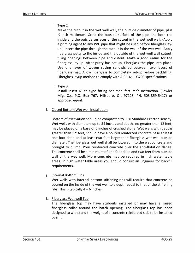
ii. Type 2 Make the cutout in the wet well wall, the outside diameter of pipe, plus ½ inch maximum. Grind the outside surface of the pipe and both the inside and the outside surfaces of the cutout in the wet well wall. (Apply a priming agent to any PVC pipe that might be used before fiberglass lay-up.) Insert the pipe through the cutout in the wall of the wet well. Apply fiberglass putty to the inside and the outside of the wet well wall cutout, filling openings between pipe and cutout. Make a good radius for the fiberglass lay-up. After putty has set-up, fiberglass the pipe into place. Use one layer of woven roving sandwiched between two layers of fiberglass mat. Allow fiberglass to completely set-up before backfilling. Fiberglass layup method to comply with A.S.T.M.-D3299 specifications.
iii. Type 3
Install Insert-A-Tee type fitting per manufacturer’s instruction. (Fowler Mfg. Co., P.O. Box 767, Hillsboro, Or. 97123. PH. 503-359-5417) or approved equal.
i. Closed Bottom Wet well Installation
Bottom of excavation should be compacted to 95% Standard Proctor Density. Wet wells with diameters up to 54 inches and depths no greater than 12 feet, may be placed on a base of 6 inches of crushed stone. Wet wells with depths greater than 12’ feet, should have a poured reinforced concrete base at least one foot deep and at least two feet larger than fiberglass wet well outside diameter. The fiberglass wet well shall be lowered into the wet concrete and brought to plumb. Pour reinforced concrete over the anti-flotation flange. The concrete shall be a minimum of one foot deep and two feet from outside wall of the wet well. More concrete may be required in high water table areas. In high water table areas you should consult an Engineer for backfill requirements.
j. Internal Bottom Ribs Wet wells with internal bottom stiffening ribs will require that concrete be poured on the inside of the wet well to a depth equal to that of the stiffening ribs. This is typically 4 – 6 inches.
k. Fiberglass Wet well Top The fiberglass top may have stubouts installed or may have a raised fiberglass collar around the hatch opening. The fiberglass top has been designed to withstand the weight of a concrete reinforced slab to be installed over it.
RIVIERA UTILITIES WASTEWATER DEPARTMENT
SECTION 401 SANITARY SEWER LIFT STATIONS 400-30
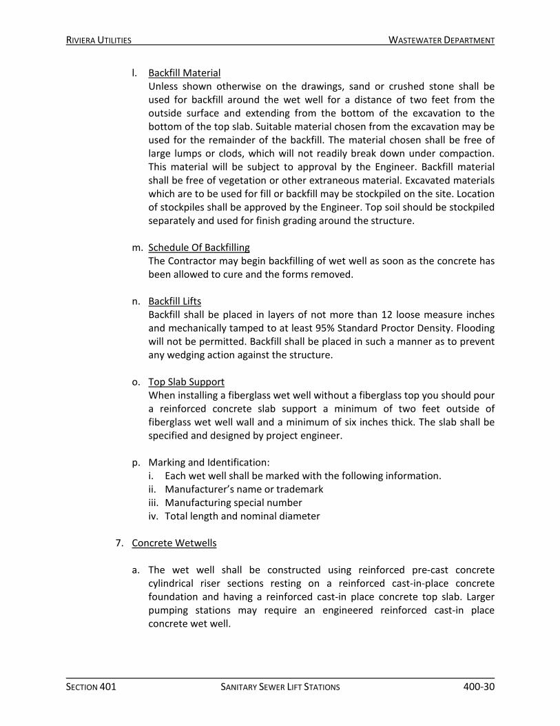
l. Backfill Material Unless shown otherwise on the drawings, sand or crushed stone shall be used for backfill around the wet well for a distance of two feet from the outside surface and extending from the bottom of the excavation to the bottom of the top slab. Suitable material chosen from the excavation may be used for the remainder of the backfill. The material chosen shall be free of large lumps or clods, which will not readily break down under compaction. This material will be subject to approval by the Engineer. Backfill material shall be free of vegetation or other extraneous material. Excavated materials which are to be used for fill or backfill may be stockpiled on the site. Location of stockpiles shall be approved by the Engineer. Top soil should be stockpiled separately and used for finish grading around the structure.
m. Schedule Of Backfilling The Contractor may begin backfilling of wet well as soon as the concrete has been allowed to cure and the forms removed.
n. Backfill Lifts Backfill shall be placed in layers of not more than 12 loose measure inches and mechanically tamped to at least 95% Standard Proctor Density. Flooding will not be permitted. Backfill shall be placed in such a manner as to prevent any wedging action against the structure.
o. Top Slab Support When installing a fiberglass wet well without a fiberglass top you should pour a reinforced concrete slab support a minimum of two feet outside of fiberglass wet well wall and a minimum of six inches thick. The slab shall be specified and designed by project engineer.
p. Marking and Identification: i. Each wet well shall be marked with the following information. ii. Manufacturer’s name or trademark iii. Manufacturing special number iv. Total length and nominal diameter
7. Concrete Wetwells
a. The wet well shall be constructed using reinforced pre-cast concrete
cylindrical riser sections resting on a reinforced cast-in-place concrete foundation and having a reinforced cast-in place concrete top slab. Larger pumping stations may require an engineered reinforced cast-in place concrete wet well.

RIVIERA UTILITIES WASTEWATER DEPARTMENT
SECTION 401 SANITARY SEWER LIFT STATIONS 400-31
b. The foundation slab shall be reinforced concrete poured on undisturbed earth. If over excavation is required, the Contractor shall place select back fill in the excavation in 6” maximum lifts and compact each lift independently until restoring excavation to desired elevation.
c. The wet well riser shall be fabricated in accordance with ASTM C478-07, “Standard Specification for Precast Reinforced Concrete Manhole Sections.”
d. Concrete shall be Type II Portland cement with 100% calcareous aggregate. Resilient connectors shall be used when installing piping through the risers. The connectors shall be in accordance with ASTM C923-07 “Standard Specification for Resilient Connections between Reinforced Concrete Manhole Structures, Pipes, and Laterals.”
e. The riser joints shall include flexible watertight gaskets in accordance with ASTM C443-05a “Standard Specification for Joints for Concrete Pipe and Manholes, Using Rubber Gaskets.” Joints in precast wet well sections shall be wrapped on the exterior with a minimum of 6 inch wide outside joint wrap at locations where the joint is below grade. Rub’R-NEK by Henry Company, Seal Wrap by Sealing Systems, Inc. or an approved equal shall be used.
f. The top slab shall be reinforced concrete, formed and cast-in-place, upon the wet well risers. The top slab shall include an access hatch cover with fall-through protection specifically sized to suit the pumping installation. The top slab shall provide other items as detailed on the plans, including, but not limited to, wet well vent, by-pass pumping suction connection, pump discharge piping wall pipes, and penetrations for small piping and electrical work.
g. Exterior Coating
i. All exterior surfaces of the wet well riser sections shall be coated with a 14-20 mils minimum dry film thickness of coal tar epoxy.
ii. Interior Lining System • All interior concrete surfaces of newly constructed wet wells,
including the bottom slab, riser, and underside of the top slab, and the pump discharge piping within the wet well, shall receive a field applied protective lining/coating system. The protective lining system shall be one of the following approved products.
• Epoxy Wet Well Lining System, Warren Environmental, Inc., S-301 • Urethane Wet Well Lining System, Sprayroq, Inc., SprayWall • Calcium Aluminate Cementitious Wet Well Lining System, Kerneos
Inc., SewperCoat 2000HS
RIVIERA UTILITIES WASTEWATER DEPARTMENT
SECTION 401 SANITARY SEWER LIFT STATIONS 400-32
8. Prerotation Basin Insert
a. The Prerotation pumping system is an automatic wet well cleaning and flow matching system as manufactured by Weir Specialty Pump or owner approved equal.
b. Materials and Fabrication i. Material shall be fiberglass ii. Minimum fluid temp: 32 deg F / Maximum fluid temp: 180 deg F
9. Access Hatch Cover
a. The types of access hatch covers include the following:
Single and multiple door non-draining angle frame access hatch covers of aluminum construction for cast-in-place installation for all new construction.
b. Reference Standards
i. Comply with applicable provisions and recommendations of the following, except as otherwise shown or specified. 15
ii. O.S.H.A. Standard 1919.23 (fall-through protection) Aluminum Association, Inc., 5th Edition – Bridge Type Structures (safety grate design)
iii. ANSI/AWS d1.2-90 Structural Welding Code for Aluminum iv. ASTM B221
c. Materials and Fabrication
i. Provide manufacturer’s standard fabricated units, modified, if necessary, to comply with the requirements. Where standard units are not available for the sizes and types required, custom fabricate units to match manufacturer’s similar units.
ii. Fabricate each unit in the shop, complete with stainless steel anchors, gaskets, hardware and accessory items as required.
d. The access covers shall be as manufactured by:
i. Halliday Products ii. U. S. F. Fabrication, Incorporated iii. Or equal
e. Covers and Frames
i. The access hatch covers and frames shall be constructed of 6061-T6 aluminum bars, angles and extrusions and 5086 diamond pattern aluminum plate of a minimum thickness of ¼”.
ii. Each unit shall be designed for a minimum loading of 300 pounds per square foot. Deflection shall not exceed 1/150th of the span.
RIVIERA UTILITIES WASTEWATER DEPARTMENT
SECTION 401 SANITARY SEWER LIFT STATIONS 400-33
iii. Frames shall be of extruded aluminum with continuous anchor flange for embedment in concrete or flange-attachment to surface of concrete, as required.
f. Accessories
i. Hinges shall be of heavy duty design. Hinge leaves shall be brass alloy or type T316 stainless steel. Hinge pins shall be 3/8” diameter grade T316 stainless steel. The hinges shall be bolted to the cover plates and frames with grade T316 stainless steel bolts and lock nuts.
ii. Each hinged cover plate shall be furnished with a grade T316 stainless steel ‘slam-lock’ with keyway protected by a threaded aluminum plug. The slam-lock shall be fastened to the grade T316 stainless steel fasteners.
iii. Each hinged cover plate shall be furnished with an aluminum lift handle. The handle shall rest flush with the surface of the cover plate and be withdrawn for use.
iv. Each hinged cover plate shall be equipped with an automatic aluminum hold open arm. The door shall lock open in the 90 degree position. Each hold open arm shall be equipped with a red vinyl handle. The hold open arm shall fasten to the frame with grade T316 stainless steel hardware.
v. Hinged cover plates of 10 square feet, or larger, shall be equipped with stainless steel torsion bars to reduce the effort required to open the covers.
g. Fall Through Protection
i. Each access frame and cover assembly shall be provided with fall through protection in accordance with OSHA Std. 1910.23.
ii. The fall through protection shall be composed of hinged aluminum grate spanning the opening.
iii. The aluminum grate shall be designed to withstand a minimum live load of 300 pounds per square foot with a deflection not to exceed 1/150th of the span.
iv. The aluminum grate openings shall be approximately 5” x 5” to allow visual inspection of the wet well and adjustment of the floats switched when the cover is opened.
v. Each aluminum grate shall be provided with a permanent hinging system. The grate shall lock in the 90 degree opened position.
vi. Each grate shall have an opening arm, with a red vinyl handle. The opening arm shall be provided with a controlled confined space entry locking device (lock by OWNER).
vii. The grate shall be painted OSHA ‘safety orange’.

RIVIERA UTILITIES WASTEWATER DEPARTMENT
SECTION 401 SANITARY SEWER LIFT STATIONS 400-34
h. Finish i. All aluminum covers shall be mill finished. Protect finish with a factory
applied coating of lacquer standard with the manufacturer. ii. All surfaces in contact with concrete shall be bituminous coated.
400.16 APPROVED PARTS LIST
COMPONENT MFG(S) PART NUMBER/DESCRIPTION
SUBMERSIBLE SOLIDS HANDLING PUMPS FLYGT, WEMCO, WILO PER SPECIFICATION
PREROTATION BASIN WEIR SPECIALTY PUMPS PER SPECIFICATION
CONTROL PANEL PRIMEX, AUTOMATION CONTROL SERVICES ARC ARMOR - PER SPECIFICATION
VARIABLE FREQUENCY DRIVES YASKAWA U1000
CONTROL FLOATS ANCHOR SCIENTIFIC ROTO FLOAT TYPE S
LEVEL SENSING RADAR ENDRESS+HAUSER MICROPILOT FMR20-1E76/0
WET WELL HATCH USF, HALLIDAY 300PSF WITH SAFETY GRATE
WET WELL BASIN LF MFG, CONTAINMENT SOLUTIONS PRESSURE TRANSMITTER* ENDRESS+HAUSER PMP51-CD21JD1PGJRKJA1
ISOLATION RING* ASHCROFT 80-xx-EBB-04T-N-000-XDJ
ISOLATION VALVES CLOW, MUELLER, AVK, DEZURIK CAST IRON, FLANGED WITH LEVER OR
WHEEL
REDVALVE SERIES 75 CAST IRON WITH WHEEL
CHECK VALVES CLOW, MUELLER, AVK, DEZURIK CAST IRON, FLANGED, LEVER/SPRING
TIDEFLEX SERIES 39 WITH SS SADDLE SUPPORT
AIR RELEASE VALVES H-TECH MODEL 986, 2” CONNECTION
YARD HYDRANT ZURN FLO-TROL
*PRESSURE TRANSMITTER AND ISOLATION RING SHOULD BE FACTORY FILLED WITH GLYCERIN.