warranty schedule spray finishing systems
TRANSCRIPT
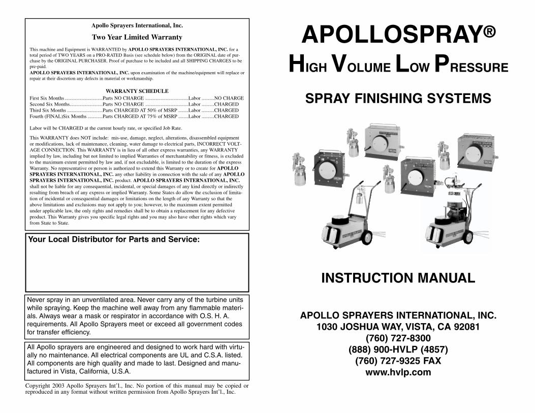
APOLLOSPRAY®
HIGH VOLUME LOW PRESSURE
SPRAY FINISHING SYSTEMS
INSTRUCTION MANUAL
APOLLO SPRAYERS INTERNATIONAL, INC.1030 JOSHUA WAY, VISTA, CA 92081
(760) 727-8300(888) 900-HVLP (4857)
(760) 727-9325 FAX www.hvlp.com
Your Local Distributor for Parts and Service:
Never spray in an unventilated area. Never carry any of the turbine unitswhile spraying. Keep the machine well away from any flammable materi-als. Always wear a mask or respirator in accordance with O.S. H. A.requirements. All Apollo Sprayers meet or exceed all government codesfor transfer efficiency.
All Apollo sprayers are engineered and designed to work hard with virtu-ally no maintenance. All electrical components are UL and C.S.A. listed.All components are high quality and made to last. Designed and manu-factured in Vista, California, U.S.A.
Apollo Sprayers International, Inc.
Two Year Limited Warranty
This machine and Equipment is WARRANTED by APOLLO SPRAYERS INTERNATIONAL, INC. for atotal period of TWO YEARS on a PRO-RATED Basis (see schedule below) from the ORIGINAL date of pur-chase by the ORIGINAL PURCHASER. Proof of purchase to be included and all SHIPPING CHARGES to bepre-paid.APOLLO SPRAYERS INTERNATIONAL, INC. upon examination of the machine/equipment will replace orrepair at their discretion any defects in material or workmanship.
WARRANTY SCHEDULEFirst Six Months ..............................Parts NO CHARGE ..................................Labor ..........NO CHARGESecond Six Months..........................Parts NO CHARGE ..................................Labor ..........CHARGEDThird Six Months ............................Parts CHARGED AT 50% of MSRP ........Labor ..........CHARGEDFourth (FINAL)Six Months ............Parts CHARGED AT 75% of MSRP ........Labor ..........CHARGED
Labor will be CHARGED at the current hourly rate, or specified Job Rate.
This WARRANTY does NOT include: mis-use, damage, neglect, alterations, disassembled equipmentor modifications, lack of maintenance, cleaning, water damage to electrical parts, INCORRECT VOLT-AGE CONNECTION. This WARRANTY is in lieu of all other express warranties, any WARRANTYimplied by law, including but not limited to implied Warranties of merchantability or fitness, is excludedto the maximum extent permitted by law and, if not excludable, is limited to the duration of the expressWarranty. No representative or person is authorized to extend this Warranty or to create for APOLLOSPRAYERS INTERNATIONAL, INC. any other liability in connection with the sale of any APOLLOSPRAYERS INTERNATIONAL, INC. product. APOLLO SPRAYERS INTERNATIONAL, INC.shall not be liable for any consequential, incidental, or special damages of any kind directly or indirectlyresulting from breach of any express or implied Warranty. Some States do allow the exclusion of limita-tion of incidental or consequential damages or limitations on the length of any Warranty so that theabove limitations and exclusions may not apply to you; however, to the maximum extent permittedunder applicable law, the only rights and remedies shall be to obtain a replacement for any defectiveproduct. This Warranty gives you specific legal rights and you may also have other rights which varyfrom State to State.
Copyright 2003 Apollo Sprayers Int’l., Inc. No portion of this manual may be copied orreproduced in any format without written permission from Apollo Sprayers Int’l., Inc.
i 24
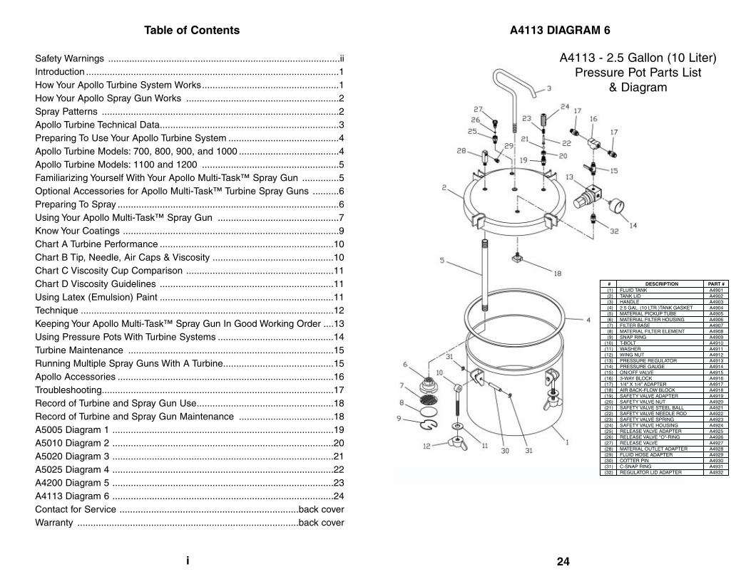
Table of Contents A4113 DIAGRAM 6
Safety Warnings ........................................................................................iiIntroduction ................................................................................................1How Your Apollo Turbine System Works....................................................1How Your Apollo Spray Gun Works ..........................................................2Spray Patterns ..........................................................................................2Apollo Turbine Technical Data....................................................................3Preparing To Use Your Apollo Turbine System ..........................................4Apollo Turbine Models: 700, 800, 900, and 1000 ......................................4Apollo Turbine Models: 1100 and 1200 ....................................................5Familiarizing Yourself With Your Apollo Multi-Task™ Spray Gun ..............5Optional Accessories for Apollo Multi-Task™ Turbine Spray Guns ..........6Preparing To Spray ....................................................................................6Using Your Apollo Multi-Task™ Spray Gun ..............................................7Know Your Coatings ..................................................................................9Chart A Turbine Performance ..................................................................10Chart B Tip, Needle, Air Caps & Viscosity ..............................................10Chart C Viscosity Cup Comparison ........................................................11Chart D Viscosity Guidelines ..................................................................11Using Latex (Emulsion) Paint ..................................................................11Technique ................................................................................................12Keeping Your Apollo Multi-Task™ Spray Gun In Good Working Order ....13Using Pressure Pots With Turbine Systems ............................................14Turbine Maintenance ..............................................................................15Running Multiple Spray Guns With A Turbine..........................................15Apollo Accessories ..................................................................................16Troubleshooting........................................................................................17Record of Turbine and Spray Gun Use....................................................18Record of Turbine and Spray Gun Maintenance ....................................18A5005 Diagram 1 ....................................................................................19A5010 Diagram 2 ....................................................................................20A5020 Diagram 3 ....................................................................................21A5025 Diagram 4 ....................................................................................22A4200 Diagram 5 ....................................................................................23A4113 Diagram 6 ....................................................................................24Contact for Service ....................................................................back coverWarranty ....................................................................................back cover
(1)(2)(3)(4)(5)(6)(7)(8)(9)
(10)(11)(12)(13)(14)(15)(16)(17)(18)(19)(20)(21)(22)(23)(24)(25)(26)(27)(28)(29)(30)(31)(32)
FLUID TANKTANK LIDHANDLE2.5 GAL. (10 LTR.)TANK GASKETMATERIAL PICKUP TUBEMATERIAL FILTER HOUSINGFILTER BASEMATERIAL FILTER ELEMENTSNAP RINGT-BOLTWASHERWING NUTPRESSURE REGULATORPRESSURE GAUGEON/OFF VALVE3-WAY BLOCK1/4" X 1/4" ADAPTER AIR BACK-FLOW BLOCKSAFETY VALVE ADAPTERSAFETY VALVE NUTSAFETY VALVE STEEL BALLSAFETY VALVE NEEDLE RODSAFETY VALVE SPRINGSAFETY VALVE HOUSINGRELEASE VALVE ADAPTERRELEASE VALVE "O"-RINGRELEASE VALVEMATERIAL OUTLET ADAPTERFLUID HOSE ADAPTERCOTTER PINC-SNAP RINGREGULATOR LID ADAPTER
A4901A4902A4903A4904A4905A4906A4907A4908A4909A4910A4911A4912A4913A4914A4915A4916A4917A4918A4919A4920A4921A4922A4923A4924A4925A4926A4927A4928A4929A4930A4931A4932
DESCRIPTION# PART #
A4113 - 2.5 Gallon (10 Liter)Pressure Pot Parts List
& Diagram

23
A4200 DIAGRAM 5
ii
SAFETY WARNINGSDO NOT USE EQUIPMENT BEFORE READING THIS SECTION
A fire or explosion hazard is present when spraying flammable materials. In order to assure safe operation of yourspray system, please read the following instructions carefully.
• Always follow coating or solvent manufacturers safety instructions and warnings.• Always spray in a well ventilated area.• Always keep the turbine system at the maximum length of hose.• Always wear eye protection and a respirator.• Always store indoors, never allow unit to freeze.• Always use original manufacturers replacement parts.• Never spray flammable materials near open flames, pilot lights or any other source of ignition.• Never alter or modify any part of this equipment; doing so can cause equipment malfunction and/or bodily injury.• Never attempt to clean any part of the turbine system while it is plugged in.• CAUTION: TO REDUCE THE RISK OF ELECTRIC SHOCK, DO NOT EXPOSE TO WATER.• Never leave spray equipment unattended. Keep away from children or any person not familiar with spray equipment.
GROUNDING INSTRUCTIONSThis product should be grounded. In the event of an electrical short circuit, grounding reduces the risk of electrical shock byproviding an escape wire for the electric current. This product is equipped with a cord that has a grounding wire and appro-priate grounding plug. The plug must be plugged into an outlet that is properly installed and grounded in accordance with alllocal codes and ordinances. Do not operate unit with a damaged cord or plug. Do not pull or carry unit by the cord. Keepaway from heated surfaces. Do not unplug by pulling on the cord.
DANGERImproper installation of the grounding plug can result in the risk of electric shock. Check with a qualified electrician if indoubt as to whether the product is properly grounded. Do not modify the plug provided. If it will not fit the outlet, have theproper outlet installed by a qualified electrician. This product is for use on a nominal 120 volt circuit and has a groundingplug similar to the one illustrated. Make sure that the turbine is connected to an outlet with the same configuration as theplug. DO NOT USE ANY ADAPTERS WITH THIS PRODUCT.
USING EXTENSION CORDSUse only a three wire extension cord with a 3-slot receptacle similar to the plug on the turbine. Make sure your extensioncord is in good condition. When using an extension cord, be sure to select one that will carry a heavy enough current for theturbine system used. An undersized cord will cause a drop in the line voltage resulting in loss of power and overheating. Ifin doubt use the next heavier gauge. The smaller the gauge number, the heavier the wire thickness. Please use the chartbelow as a guide to selecting the proper size extension cord.
For length less than: Use extension gauge:
25ft 16AWG
50ft 14AWG
100ft 12AWG
150ft 10AWG
FIRE OR EXPLOSION HAZARD
FLUID SECTION - SOLVENTSHalogenated Hydrocarbon solvents can cause an explosion when used with aluminum or galvanized components in aclosed (pressurizable) fluid system (pumps, heater, filters, valves, spray guns, tanks, etc.). The explosion could cause seri-ous injury, death and/or substantial property damage. Cleaning agents, coatings, paints, etc. may contain Halogenatedhydrocarbon solvents. The manufacturer of this equipment uses aluminum components that will be affected by HalogenatedHydrocarbon solvents. DO NOT USE HALOGENATED HYDROCARBONS WITH THIS EQUIPMENT.
EXPLANATION OF THE HAZARDThere are three key elements to the Halogenated Hydrocarbon (HHC) solvent hazard. These elements are:
1. The presence of HHC 2. Aluminum or galvanized parts3. Equipment capable of withstanding pressure
When all three elements are present, the result can be an extremely violent explosion. The reaction can be sustained withvery little aluminum or galvanized metal; any amount of aluminum is too much. The reaction is unpredictable. Prior use of anHHC solvent without incident (corrosion or explosion) does NOT mean that such use is safe.HALOGENATED SOLVENTS – definition: Any hydrocarbon solvent containing any of the elements as listed below: Consultyour material supplier to determine whether your solvent or coating contains Halogenated Hydrocarbon Solvents.
Fluorine (F) “-fluor-”Bromine (Br) “-bromo-”Examples (not all-inclusive):FLUOROCARBON SOL-VENTS:DichlorofluoromethaneTrichlorofluoromethaneCHLORINATED SOLVENTS:
Carbon tetrachlorideChloroform
Ethylene DichlorideBROMINATED SOLVENTS:Ethylene DibromideMethylene chlorobromideMethyl bromineTRICHLOROETHANE:
TrichloroethyleneMonochlorotolueneChlorine (CL) “-chloro-”Iodine (I) “-iodo-”METHYLENE CHLORIDEORDICHLOROMOETHANEMonochlorobenzene
OrthodichlorobenzenePorchloroethyleneIODINATED SOLVENTS:N-butyl iodideMethyl IodideEthyl IodidePropyl iodide
(1)(2)(3)(4)(5)(6)(7)(8)(9)
(10)(11)(12)(13)(14)(15)(16)(17)
HANDLEHANDLE LOCK NUTFLUID OUTLETFLUID ADAPTERRELIEF VALVE STEMRELIEF VALVE SPRINGRELIEF VALVE PLUGAIR REGULATOR ASSEMBLY0-30 PSI PRESSURE GAUGECUP TOP CASTING ASSEMBLYCHECK VALVECHECK VALVE SPRINGCHECK VALVE BRACKETCHECK VALVE SCREWMATERIAL PICKUP TUBE, S.S.CUP TOP GASKET2-QUART CUP WITH TEFLON
A4601A4602A4603A4150A4608A4615A4617A4607A4211A4604A4605A4612A4613A4614A4610A4609A4611
DESCRIPTION# PART #
A4200- 2 Quart (2 Liter)Pressure Pot Parts List
& Diagram

1 22
APOLLOSPRAY®
Multi-Task™ SPRAY FINISHING SYSTEMS
CONGRATULATIONS!! You have just purchased the finestHVLP air turbine system available.You are about to enjoy thegreat benefits of your ApolloSpray Multi-Task™ spray finishingsystem. Our product designs are the result of many years ofexperience in manufacturing HVLP spray equipment. We havepainstakingly worked and consulted with professional spray fin-ishers and coatings manufacturers to bring you this versatile,well-engineered tool.
Whether you are new to spray finishing, or you have spray fin-ished previously, or, you are just new to HVLP spraying, thereare some basic spray finishing guidelines that will help you toachieve the best results and optimum success from your newequipment. Reading this information carefully and followingthese simple steps will ensure that you get the best perform-ance and results from your new Apollo HVLP spray system.
Check the contents of your box. The following are included:
• Turbine unit• Slim-Flex™ air hose• Spray Gun• Instruction Manual
How Your Apollo Turbine System WorksYour turbine system has three components: the turbine unit, theair hose and the spray gun. The turbine unit, when connectedto the correct electrical power supply, and with the on/off switchin the “on” position provides a continuous source of clean,warm, dry, High Volume Low Pressure air (as measured incubic feet per minute - CFM). The air hose connects the turbineunit to the spray gun. Air flows through the air hose to the noz-zle of the specially designed Apollo Multi-Task™ spray gun.Atomization of the coating is achieved when the air mixes withthe stream of fluid passing through the tip/nozzle. This lowpressure atomization principle achieves minimum misting (over-spray) to the spray environment.
A5025 DIAGRAM 4
(1)(2)(2)(3)(4)(6)(6)(6)(6)(6)(7)(8)(9)
(10)(11)(12)(13)
(13a)(14a)(14b)(15)(15)(15)(15)(15)(16)(17)(18)(19)(20)(21)(22)(23)(24)(25)(26)(27)(28)(29)(30)(31)(32)(33)(35)
A5200A5201A5297A5203A5204A5206A5207A5208A5208-2A5209A5210A5211A5212A5213A5214A5215A5202A5257A5216A5217A5218A5219A5220A5220-2A5221A5222A5223A5224A5225A5226LA5227A5228A5229A5230A5232A4952A5271A5278A5270A5266A5272A5280A4951A5254
DESCRIPTION# PART #AIR CAP RINGAIR CAP # 1AIR CAP # 2AIR DISTRIBUTOR PLATE (STAINLESS)AIR DISTRIBUTOR SPRING (STAINLESS)FLUID NOZZLE/JET (STAINLESS) .75MMFLUID NOZZLE/JET (STAINLESS) 1.00MMFLUID NOZZLE/JET (STAINLESS) 1.50MMFLUID NOZZLE/JET (STAINLESS) 2.00MMFLUID NOZZLE/JET (STAINLESS) 2.50MMFLUID NOZZLE GASKETAIR FEED CONNECTORGUN CASTING (MAIN BODY)TRIGGER BUSHINGTRIGGER PIVOT SCREW (STAINLESS)TRIGGER SCREW WASHERAIR BLANKING PLUGO.S. CONTROLUPPER PORT INSERTAIR BLANKING PLUGNEEDLE (STAINLESS) .75MMNEEDLE (STAINLESS) 1.00MMNEEDLE (STAINLESS) 1.50MMNEEDLE (STAINLESS) 2.00MMNEEDLE (STAINLESS) 2.50MMNEEDLE SPRING (STAINLESS)FLOW SCREW INSERTMATERIAL FLOW ADJUSTING SCREWGUN CASTING (HANDLE)HANDLE TUBEAIR HOSE QUICK RELEASE COUPLER (MALE)GLAND SEALGLAND SEAL (STAINLESS)TRIGGER (STAINLESS)AIR FEED TUBE AND NON-RETURN VALVECENTER BOLT/PICK-UP TUBEYOKELEVERCUP TOP CASTING90 DEGREE MINIATURE BRASS BLOCKCUP TOP LOCK NUTCUP TOP GASKET (WHITE POLY)ROUND BOTTOM 1 QUART Q/R CUP; TEFLON LINEDFLUID CONNECTOR 3/8" (STAINLESS)

21 2
HOW YOUR APOLLO SPRAY GUN WORKS
Apollo HVLP Multi-Task™ Turbine Spray Guns arebleeder type spray guns. When the turbine isturned on, air will constantly flow through the aircap (#2). This ensures the longevity of your equip-ment. Air also flows through the air feed tube (#25)to pressurize the cup to deliver fluid to the tip/noz-zle (#6). When the paint flow screw (#18) is openedand the trigger (#24) pulled back, fluid flowsthrough the tip/nozzle mixing with the air flow deliv-ered from the air cap and projects a fine atomizedmist to your work piece.
Your spray gun offers you many options. You canadjust (click) the air cap (#2) to three positions. Onewill produce a horizontal pattern for sprayingacross, the second will produce a vertical patternfor spraying up and down, and the third will producea round pattern to spray small or narrow pieces.
APOLLO Multi-Task™ TURBINE SPRAY GUNS
1 2 3APOLLO
SPRAYERS
APOL
LO
SPRA
YE
RS
AP
O
LLO
SPRAYER
S
SPRAY PATTERN
Fig. 1 Use this position when spraying across from side to side.Fig. 2 Use this position when spraying from top to bottom.Fig. 3 Use this position for spotting small objects, corners and sharp angles.
A5005LPRODUCTION GUN
A50208oz CUP
A5005PRODUCTION GUN
A5010BAYONET CUP
A5010LBAYONET CUP
A5025ROUND
BOTTOM CUP
A5020 DIAGRAM 3
(1)(2)(2)(3)(4)(6)(6)(6)(6)(6)(7)(8)(9)
(10)(11)(12)(13)
(13a)(14a)(14b)
(15)(15)(15)(15)(15)(16)(17)(18)(19)(20)(21)(22)(23)(24)(25)(26)(27)(28)(29)(35)
AIR CAP RINGAIR CAP # 1AIR CAP # 2AIR DISTRIBUTOR PLATE (STAINLESS)AIR DISTRIBUTOR SPRING (STAINLESS)FLUID NOZZLE/JET (STAINLESS) .75MMFLUID NOZZLE/JET (STAINLESS) 1.00MMFLUID NOZZLE/JET (STAINLESS) 1.50MMFLUID NOZZLE/JET (STAINLESS) 2.00MMFLUID NOZZLE/JET (STAINLESS) 2.50MMFLUID NOZZLE GASKETAIR FEED CONNECTORGUN CASTING (MAIN BODY)TRIGGER BUSHINGTRIGGER PIVOT SCREW (STAINLESS)TRIGGER SCREW WASHERAIR BLANKING PLUGO.S. CONTROLUPPER PORT INSERTAIR BLANKING PLUGNEEDLE (STAINLESS) .75MMNEEDLE (STAINLESS) 1.00MMNEEDLE (STAINLESS) 1.50MMNEEDLE (STAINLESS) 2.00MMNEEDLE (STAINLESS) 2.50MMNEEDLE SPRING (STAINLESS)FLOW SCREW INSERTMATERIAL FLOW ADJUSTING SCREWGUN CASTING (HANDLE)HANDLE TUBEAIR HOSE QUICK RELEASE COUPLER (MALE)GLAND SEALGLAND NUT (STAINLESS)TRIGGER (STAINLESS)AIR FEED TUBE AND NON RETURN VALVEMATERIAL PICK UP TUBELID ASSEMBLYGASKET (WHITE POLY)8-OZ. PLASTIC CUPFLUID CONNECTOR, 1/4" (STAINLESS)STORAGE LIDPACK OF (4) 8-OZ CUPS WITH LIDS
A5200A5201A5297A5203A5204A5206A5207A5208A5208-2A5209A5210A5211A5212A5213A5214A5215A5202A5257A5216A5217A5218A5219A5220A5220-2A5221A5222A5223A5224A5225A5226LA5227A5228A5229A5230A5232A5403A5404A5402A5401A5252A5400A5405
DESCRIPTION# PART #

3 20
MODEL 700—2 Stage motor 4.5psi (.31 bar) 14’(4.26m) Slim-Flex™ air hose, Apollo HVLPSpray Gun. 32lbs (14.5kg), 110v, 60Hz, 10amps,1.5hp. (240v, 50Hz, 5amps).
MODEL 800—3 Stage motor, 5.5psi (.37 bar) 24’(7.31m) Slim-Flex™ air hose, Apollo HVLPSpray Gun. 41lbs (18.6kg), 110v, 60Hz, 11amps,1.65hp. (240v, 50Hz, 5.5amps).
MODEL 900—3 Stage motor, 6.0psi (.41 bar) 34’(10.36m) Slim-Flex™ air hose, Apollo HVLPSpray Gun. 50lbs (22.7kg), 110v, 60Hz, 12amps,1.75hp. (240v, 50Hz, 6amps).
MODEL 1000—4 Stage motor, 8.0psi (.55bar)34’ (10.36m) Slim-Flex™ air hose, Apollo HVLPSpray Gun. 40lbs (18.2kg), 110v, 60Hz, 13amps,1.85hp. (240v, 50Hz, 6.5amps).
MODEL 1100—Dual Turbines, 3.5 - 10psi. (24bar, 41 bar, 69 bar) 44’ (13.41m) Slim-Flex™ airhose, Apollo HVLP Spray Gun. 77lbs (35kg),110v, 60Hz, 15amps, 2.6hp. (240v, 50Hz,7.5amps).
MODEL 1200—Dual Turbines, 3.5 - 10psi. (24 bar, 41 bar, 69 bar) 44’ (13.41m) Slim-Flex™air hose, 40’ (12.19m) Fluid Hose, 2.5 gallon (10Liter) Pressure Pot, Platform, Fluid FeedSystem, Apollo HVLP Spray Gun. 107lbs(48.54kg), 110v, 60Hz, 15amps, 2.6hp. (240v,50Hz, 7.5amps).
APOLLO TURBINE UNITS A5010 DIAGRAM 2
(1)(2)(2)(3)(4)(6)(6)(6)(6)(6)(7)(8)(9)
(10)(11)(12)(13)
(13a)(14a)(14b)
(15)(15)(15)(15)(15)(16)(17)(18)(19)(20)(21)(22)(23)(24)(25)(26)(27)(28)(29)(30)(31)(32)(33)(33)(35)
AIR CAP RINGAIR CAP # 1AIR CAP # 2AIR DISTRIBUTOR PLATE (STAINLESS)AIR DISTRIBUTOR SPRING (STAINLESS)FLUID NOZZLE/JET (STAINLESS) .75MMFLUID NOZZLE/JET (STAINLESS) 1.00MMFLUID NOZZLE/JET (STAINLESS) 1.50MMFLUID NOZZLE/JET (STAINLESS) 2.00MMFLUID NOZZLE/JET (STAINLESS) 2.50MMFLUID NOZZLE GASKETAIR FEED CONNECTORGUN CASTING (MAIN BODY)TRIGGER BUSHINGTRIGGER PIVOT SCREW (STAINLESS)TRIGGER SCREW WASHERAIR BLANKING PLUGO.S. CONTROLUPPER PORT INSERTAIR BLANKING PLUGNEEDLE (STAINLESS) .75MMNEEDLE (STAINLESS) 1.00MMNEEDLE (STAINLESS) 1.50MMNEEDLE (STAINLESS) 2.00MMNEEDLE (STAINLESS) 2.50MMNEEDLE SPRING (STAINLESS)FLOW SCREW INSERTMATERIAL FLOW ADJUSTING SCREWGUN CASTING (HANDLE)HANDLE TUBEAIR HOSE QUICK RELEASE COUPLER (MALE)GLAND SEALGLAND NUT (STAINLESS)TRIGGER (STAINLESS)AIR FEED TUBE AND NON RETURN VALVECENTER BOLT/PICK-UP TUBEYOKELEVERCUP TOP CASTING90 DEGREE MINIATURE BRASS BLOCKCUP TOP LOCK NUTCUP TOP GASKET (WHITE POLY)QUICK RELEASE CUPQUICK RELEASE CUP (TEFLON COATED)FLUID CONNECTOR, 3/8" (STAINLESS)
A5200A5201A5297A5203A5204A5206A5207A5208A5208-2A5209A5210A5211A5212A5213A5214A5215A5202A5257A5216A5217A5218A5219A5220A5220-2A5221A5222A5223A5224A5225A5226LA5227A5228A5229A5230A5232A5274A5271A5278A5270A5266A5272A5280A5275A5277A5254
DESCRIPTION# PART #

19 4
PREPARING TO USE YOUR APOLLO TURBINE SYSTEM
Connect the air hose to the turbine. On the turbine unit, pullback the spring loaded quick disconnect coupler and insert themale connector on the air hose into the turbine connector.Release the ring. (Model 700 turbine will have a screw-on con-nector). Your air hose will be locked into place. To disconnect,pull back on the connector to release the air hose. CAUTION:If you have just finished spraying, the metal coupler at the tur-bine end may be hot.
Plug the electric cord into a correctly grounded electrical out-let. Be sure the electric current is the correct voltage. If youneed to use an extension cord, be sure it is at least 12 gaugewire and has a correctly grounded outlet. (240v units for useoutside of the United States may be supplied with just an elec-trical cord. A correct plug must be installed prior to use. Makesure the ground wire is properly connected).
Select a safe, well ventilated area where you will spray yourwork piece. Locate your turbine unit away from the area whereyou will be directly spraying. Do not cover or enclose the tur-bine. It is important to draw cool/ambient air through the unitfor optimum performance. Avoid placing the turbine in a warmenvironment or in direct sunlight.
APOLLO TURBINE MODELS: 700, 800, 900 AND 1000
Model 700, 800 and 1000 have one air hose outlet on the sideof the unit and are designed to run one spray gun. The model1000 has the capability to run two spray guns at the sametime with an optional Y connector (Part #A4227). Model 900has two independent air outlets. This unit is supplied with oneoutlet capped. To use two spray guns at the same time, thecap needs to be removed and a quick disconnect couplerinstalled (A2070). When using only one spray gun, always besure that one outlet is capped.
A5005 DIAGRAM 1
DESCRIPTION# PART #(1)(2)(2)(3)(4)(6)(6)(6)(6)(6)(7)(8)(9)
(10)(11)(12)(13)
(13a)(14a)(14b)
(15)(15)(15)(15)(15)(16)(17)(18)(19)(20)(21)(22)(23)(24)(35)
AIR CAP RINGAIR CAP # 1AIR CAP # 2AIR DISTRIBUTOR PLATE (STAINLESS)AIR DISTRIBUTOR SPRING (STAINLESS)FLUID NOZZLE/JET (STAINLESS) .75MMFLUID NOZZLE/JET (STAINLESS) 1.00MMFLUID NOZZLE/JET (STAINLESS) 1.50MMFLUID NOZZLE/JET (STAINLESS) 2.00MMFLUID NOZZLE/JET (STAINLESS) 2.50MMFLUID NOZZLE GASKETAIR FEED BLANKING SCREW (STAINLESS)GUN CASTING (MAIN BODY)TRIGGER BUSHINGTRIGGER PIVOT SCREW (STAINLESS)TRIGGER SCREW WASHER AIR BLANKING PLUGO.S. CONTROLUPPER PORT INSERTAIR BLANKING PLUGNEEDLE (STAINLESS) .75MMNEEDLE (STAINLESS) 1.00MMNEEDLE (STAINLESS) 1.50MMNEEDLE (STAINLESS) 2.00MMNEEDLE (STAINLESS) 2.50MMNEEDLE SPRING (STAINLESS)FLOW SCREW INSERTMATERIAL FLOW ADJUSTING SCREWGUN CASTING (HANDLE)HANDLE TUBEAIR HOSE QUICK RELEASE COUPLER (MALE)GLAND SEALGLAND NUT (STAINLESS)TRIGGER (STAINLESS)FLUID CONNECTOR, 3/8" (STAINLESS)
A5200A5201A5297A5203A5204A5206A5207A5208A5208-2A5209A5210A5246A5212A5213A5214A5215A5202A5257A5216A5217A5218A5219A5220A5220-2A5221A5222A5223A5224A5225A5226LA5227A5228A5229A5230A5254

5 18
APOLLO TURBINE MODELS 1100 AND 1200
Model 1100 and 1200 have three independent air outlets on theback of the unit with the option of running one, two or three sprayguns at the same time. The units come supplied with one outletwith a quick disconnect coupler and two outlets capped. It is nec-essary to uncap each extra outlet and attach a quick disconnectcoupler (A2070) when operating additional spray guns. Always besure to cap any unused air outlet.
There are two switches on the model 1100 and three switches onthe model 1200. Machine Off: All switches in Off position. LowPower: Right Switch in On position (3psi). Medium Power: RightSwitch in Off position and Left Switch in On position (6psi). (Twocooling fans located behind the two rectangular filters in the front ofthe unit operate automatically). High Power: Left and RightSwitch in On position (10psi). (Both cooling fans operate automati-cally). The Model 1200 operates the same as the Model 1100 butadds a 2.5 gallon (10 liter) pressure pot, a platform for the pressurepot plus an automatic fluid feed system to the unit. This gives theoption of continuous production spraying. The Model 1200 containsa grounded outlet for the automatic fluid feed system which is oper-ated by the third switch (far left) on the unit. See Using PressurePots for additional information.
As a general guide, use low power for thin viscosity materials,medium power for slightly thicker coatings and high power forthicker/heavier viscosities. Refer to viscosity chart (D) or call Apollotechnical support 888-900-HVLP (4857) for further information.
FAMILIARIZING YOURSELF WITH YOUR APOLLOMulti-Task™ SPRAY GUN
Cup Guns: On Apollo MultiTask™ Spray Gun Model A5010 andA5025 (bayonet style cups), slide the lever to one side, releasingthe cup from the holding pins on the cup. Reverse the procedureto install the cup onto the spray gun body. Make sure the cup issecure. On bayonet style cups, be sure the cup is centered on thegasket under the cup top. CAUTION: Do not force the lever orover tighten once the cup is secure. Over tightening can causethe cup pins to bend the cup which can alter the flat surface ofthe cup rim and cause the spray gun to leak.
Familiarize yourself with the controls on the spray gun. There arethree principal controls. The rotating air cap (#2), the material flowscrew (#18) and the air cap locking ring (#1). Click the rotating aircap into each position. Horizontal, Vertical and 45°. When the aircap is in the 45° position the pattern is round. This is useful for
RECORD OF TURBINE & SPRAY GUN MAINTENANCE
DATE MAINTENANCE PERFORMED
RECORD OF TURBINE & SPRAY GUN USE
MODEL SERIAL # DATE PURCHASED
DATE USED HOURS USED TOTAL HOURS
Turbine Recommended Maintenance: Clean and/or change pre-filterand/or cartridge filter elements every 50 hours or when necessary. SeePg. 15 - for the appropriate filter replacement for your model.
Spray Gun Recommended Maintenance: Check: Cup gasket (#32 or#28 on A5020), tip/nozzle gasket (#7), Gland seal (#22), air cap (#2),tip/nozzle (#6) and needle assembly (#15) every 50 hours or when neces-sary. Clean or replace parts as needed. Spray gun maintenance kit part#A5320.

17 6
TROUBLESHOOTING
1. Paint cup full, HVLP air is supplied to the spray gun.Trigger is pulled and no paint comes out—Reason: Cupnot pressurizing.
Check:A) Air Feed Tube/one way air valve (#25)B) Air Feed Connector (#8)C) Cup is screwed or clamped on tightD) Cup top gasket is not damaged.E) On Model A5010, Look under Cup Top Lid (#29).
Locate the “C” shaped tube. Check for blockage.
2. When spray gun is connected to a turbine and the turbineis on, air continually flows through the air cap even if thetrigger is not pulled. Response: This is correct. All APOLLOturbine spray guns are “bleeder” type guns. This is neces-sary and desirable to ensure longevity of the turbine motor.
3. If you think that you are getting too much “overspray”Try:
A) Moving the spray gun closer to the workB) Closing down the fluid flowC) Reducing the air power (use optional O/S
control #13A).D) Considering a smaller tip/needle assembly
4. If the sprayed surface is not flat and level after drying(orange peel effect) Try:
A) Increasing air power (Model 1100/1200)B) Thinning the coating more.
5. If the finish looks like “dry mist”.Try:A) Increasing the fluid flowB) Moving the spray gun slowerC) Moving the spray gun closer to the work pieceD) Thinning the coating more.
Additional questions can be answered by Apollo SprayersTechnical support 888-900-HVLP (4857).
spraying small, narrow pieces of work. (Paint flow will increase whenusing the 45° position and it is usually necessary to reduce the paintflow by adjusting the flow screw (#18). (See Diagram Spray Patterns,Bottom, Pg. 2). Next, turn the material flow screw (#18) anti or counterclockwise to open or release more fluid, clockwise to reduce or closematerial flow. Last, loosen the air cap locking ring (#1) one or two turns.This will feather the top and bottom of the fan pattern and slightlyreduce the fan pattern size. (See Paragraph 2, Pg. 8).
OPTIONAL ACCESSORIES FOR APOLLO MULTI-TASK™TURBINE SPRAY GUNS
Option One: In diagram (1,2,3 or 4), locate the blanking cap (#13).Most Apollo turbine spray guns are fitted with this blanking cap. Youcan remove the cap and install the upper port insert (#14A) and upperport plug (#14B). This gives you the option to attach your air hoseonto this port instead of onto the handle. To install, unscrew blankingcap (#13). Screw in the upper port insert and plug. To use this port,unscrew the male hose coupler (#21) and screw onto the upper portinsert. Take the upper port plug and screw it onto the threads at thebottom of the handle. Reverse these two fittings to use the air hosecoupled to the handle. (Note: some spray guns will already be fittedwith the upper port insert and plug).
Option Two: This will allow you to control the air flow and create tex-tured or splatter paint effects. To install, remove the blanking cap (#13)or the upper port insert (#14A) and the upper port plug (#14B). ScrewOS Control (#13A) into the upper port on the spray gun. Afterinstalling the OS control, turn the adjusting screw as far as you can,counter (anti) clockwise (open). Always use in the full open positionunless it is necessary to reduce the flow of air, or to create a texturedor splatter effect. See instructions supplied with the OS Control forproper use. If you have questions, call Apollo technical support888 900-HVLP (4857).
PREPARING TO SPRAY
You should now be ready to spray your coating of choice on your workpiece. Good quality results with your APOLLO Multi-Task™ spray fin-ishing equipment are a combination of careful preparation of yourproject, a proper spraying environment, a basic knowledge of thecoatings you will be using and how these coatings work with yourAPOLLO HVLP spray equipment.
No project will look good unless you have properly prepared the sur-face for the finish application. If your project requires sand-

7 16
ing, sand all imperfections and clean the surface to be sprayed. Besure the environment in which you will be working is clean, proper-ly ventilated and that a moderate temperature is maintained. Itshould be neither excessively hot or cold. 70° F (21°C) is the opti-mum.
USING YOUR APOLLO Multi-Task™ SPRAY GUN
Your APOLLO Multi-Task™ Spray Gun is High Volume LowPressure. It only uses from 3psi—10psi (depending on your turbineunit) of air pressure measured at the air cap (#2). All passages andair ports are much larger than a conventional spray gun. If one ofthese air passages becomes blocked, or build up of material startsto occur, your spray pattern will become distorted. Always keepyour spray gun clean. Your APOLLO Multi-Task™ spray gun comesfitted with a 1mm tip/nozzle (#6) and needle (#15), inscribed with anumber 2. This is a general purpose size that is suited to most thinto medium viscosity fluids. Using this size tip/nozzle and needleyou can achieve a 1/4" line up to a 12" fan pattern, simply by rotat-ing the air cap (#2) to the desired fan pattern type (See Spray GunDiagram Pg. 2), opening the material flow screw (#18) counter(anti)-clockwise and moving the spray gun closer or further awayfrom your work piece. A little practice will enable you to master thistechnique. For best finish results with different fluid viscosities (verythin viscosity to higher viscosity) an alternative tip/nozzle, needleand air cap should be selected. Refer to Chart B.
PRACTICE: Remove the cup from your spray gun. Fill it approxi-mately half way with some water. (Do not worry! All fluid passagesare stainless steel and the cup Teflon® coated). Attach the cup tothe body of the spray gun. Attach the spray gun to the air hose.Turn the turbine unit on. You will notice air is now flowing throughthe air cap, this is normal and correct. Position the air cap (#2) inthe horizontal position, turn the material flow screw (#18) counterclockwise approximately 1 to 1 1/2 turns. Point the spray gun awayfrom yourself (and anyone else) and pull the trigger all the wayback. You should see a “V” shaped mist (or triangle) called a fanpattern. Now, with the trigger depressed, slowly begin to turn thematerial flow screw (#18) clockwise (closing). Notice that the fanpattern is beginning to get smaller. Now, reverse this and notice thepattern get larger. Take a large piece of cardboard and direct thepattern at the surface. Turn the material flow screw 2 full turns andhold the spray gun approximately 6" from the surface.
A4500—2 Quart (2 liter) RemoteSystem. For use with 800, 900, 1000
A4550—2.5 Gallon (10 liter) CartSystem. For use with 800, 900, 1000
A5257—O/S Control A4227—Y Connector for model 700,800 or 1000 for multiple spray guns.
A4113—2.5 Gallon (10 liter) Pressure Pot
APOLLO ACCESSORIES
A4200—2 Quart (2 liter) Pressure Pot
Shown with Model 800
Shown with Model 1000
A5318—Spray GunCleaning Kit
A4950—Round Bottom Cup Assembly
A5269—8 oz. MiniatureCup Assembly
A5319—Spray Gun Maintenance Kit,With Case

15 8
RUNNING MULTIPLE SPRAY GUNS WITH A TURBINE
It is possible to run models 700, 800 and 1000 with two sprayguns at the same time by installing Part # A4227, “Y” connec-tor to the turbine outlet port. It is important to note that if the“Y” connector is installed and only one spray gun operated,the 2nd outlet must be capped or closed so that performanceto the single spray gun will not be affected.
TURBINE MAINTENANCE
The turbine unit needs virtually no maintenance. The motor hassealed bearings that are pre-lubricated. No service is necessary.Periodically, the turbine air filters and pre-filters should be exam-ined. Clean filters are critical to good performance and equipmentlongevity. Models 700, 800, 900 and 1000 have 2 replaceablecartridge filter elements. Models 1100 and 1200 have 5 replace-able cartridge filter elements. (Do not forget the one underneaththe chassis). Remove the two hex-head securing nuts in order toremove the cartridge filter elements for cleaning or replacement.Blow excess dust and dirt with an air compressor. Dirty filters willreduce the air being drawn through the motor, causing the unit torun abnormally hot, diminish spray performance and reduce thelife of the motor. Clean and/or replace filters and pre-filters whenyou suspect they can no longer be cleaned. Use the maintenancerecord sheet on Pg. 18 to keep track of your equipment use.
PRE-FILTER SETMODEL FILTER SET PART # PART #
700
800
900
1000
1100
1200
A4129
A4171
A4171
A4171
A4153
A4153
A4058
A4096
A4096
A4096
A4096 (2), A4095 (1)
A4096 (2), A4095 (1)
Pull the trigger. Observe the outline and size of the pattern.Now, turn the material flow screw clockwise (closing). Movethe spray gun an inch or two closer to the surface. Pull thetrigger. Notice the pattern has become smaller. You can con-tinue reducing the material flow and move the spray gun evencloser to the surface and the pattern will continue to getsmaller and smaller. Next, rotate the air cap to a 45° position(See Spray Patterns, Pg. 2). Vary the material flow and thedistance of the spray gun from the work surface. Notice thechange in pattern size.
Finally, there is one additional control to learn. If you loosenthe air cap locking ring (#1), approximately 1—2 turns, youcan also control the fan pattern size and trim/feather the edgeof the fan pattern itself. This should be considered a second-ary control, the primary fan pattern size being adjustedbetween fluid flow and distance of the spray gun from thework piece.
Caution: Even when the turbine unit is turned off, pressurewill remain in the spray cup. If you pull the trigger back, astream of fluid will flow. To prevent accidents, turn materialflow screw (#18) clockwise until it is completely closed. Thetrigger is now locked in the closed position.
Note: It is not necessary to empty and clean your spray gunwhen you pause between applications. Be sure, however, toclean your spray gun thoroughly at the end of your work ses-sion. It is a bad idea to leave paint in your spray gunovernight. Extra caution should be taken when spraying coat-ings that have a catalyst or hardener added since many ofthese coatings have short pot life. These coatings can hardenin your spray gun quickly, making cleaning difficult or impossi-ble. Read the coatings manufacturer’s instructions regardinghow much time you have before catalyst/hardener begins toset up.

9 14
KNOW YOUR COATINGS
Coating PropertiesCoatings are a blend of resins and additives to create a prod-uct that will provide a protective and beautifying surface toyour work piece. Different resins have different properties. It isimportant to use the correct coating to achieve a desiredresult. Manufacturers of coatings can control the resin solidscontent, production viscosity, sheen, color, flow-out enhance-ment and other properties as well. Some products offer waysto adjust the coating properties such as speeding up or slow-ing down the drying time, adding catalysts to strengthen themolecular bond or adding flatting agents to lower the sheen.Manufacturers will often give some guidelines on how to thintheir product for spray application. There are many differenttypes of spray equipment in use. Coatings manufacturers can-not address all of them. It is important for you as a finisher tounderstand your spray equipment and to use common senseto arrive at the correct fluid viscosity to produce the best possi-ble results with the selected coating and the chosen equipmenttechnology.
Your Choice of Coatings and Viscosity
Extremely thin, watery or light bodied fluids such as inks, ani-line dyes and oil stains can generally be used straight from thecan. Most waterbased finishing products are also formulated tobe used straight from the can without thinning with a 3 stageor larger turbine. Most other coating products will need to bethinned anywhere from 10% to 50% depending on the avail-able air pressure of the turbine model and the properties of thecoating selected. (See Chart A) It is also necessary to selectan alternative tip/nozzle, needle and air cap for the appropriatefluid viscosity (See Chart B)
Apollo Multi-Task™ HVLP Turbine Properties
Each Apollo turbine unit offers the finisher a maximum operat-ing pressure. This pressure is determined by the size and out-put of the unit you have selected. The maximum available pres-sure will have a direct bearing upon the viscosity of the fluidthat you choose to spray. Atomizing pressure and fluid viscositydirectly relate to the efficiency of the equipment operation andthe quality of the results that you will achieve.
USING PRESSURE POTS WITH TURBINE SYSTEMS
Any Apollo turbine system can be used with a remote cup assem-bly or pressure pot. Apollo offers the following options:
A4200—2qt. (2 liter) cup (Stainless steel fluid parts/Teflon® lined cup)A4015—2.5 gal. (10 liter) pressure pot (supplied with model 1200)A4113– 2.5 gal. (10 liter) deluxe pressure pot
When using a remote cup or pressure pot, it is necessary to intro-duce compressed air to pressurize the remote pot to move the fluidfrom the pot to the tip/nozzle of the spray gun. In general 5 p.s.i. issufficient for most average viscosity fluids in order to deliver theproper flow of fluid to the tip/nozzle (#6). Higher pressure wouldonly be necessary for a heavier viscosity fluid. A good test to deter-mine the correct fluid delivery would be to first, pressurize the pot.DO NOT turn on the turbine. Pull the trigger of the spray gun until astream of fluid flows from the tip/nozzle. Adjust the pressure untilthe fluid drops off or bends at approximately 2 1/2 inches (6.35cm).Pot pressure should be correct at this point.
Apollo offers a 2 quart (2 liter) system (A4500) and a 2.5 gallon (10liter) system (A4550) (See Accessory Page). These are completecompatible add-ons to your turbine system that will expand your sys-tem to production capability.
NOTE: When extending the spray gun higher than 5’ – 6’ (1.5m – 2m) above thelevel of the pressure pot, fluid delivery may decrease. There are two options toadjust for this situation. Option 1: Increase pot pressure a few pounds and reducethe flow of fluid to the spray gun when spraying at lower levels and increase fluidflow when the spray gun becomes elevated and you notice that fluid delivery slowsdown. Option 2: Elevate the pressure pot to a higher level so that you will not haveto extend the spray gun higher than 4’ (1.2m) above the pressure pot.
SAFETY PRECAUTION: Always depressurize the remote pot usingthe safety valve when the equipment will be idle. This will preventexcess fluid from remaining in the fluid hose, and prevent a possibleaccident should the trigger be pulled and paint streams from thespray gun.
Always ensure that the remote cup is tightly sealed and all gasketsare in good shape in order to prevent air and fluid leaks.
Be sure to flush and clean fluid hose at the end of a work session.
For smaller jobs, you can insert a one gallon can inside the 2.5 gal-lon (10 liter) pressure pot. This will keep the inside of the pot clean.(It may be necessary to remove the material filter housing (Diagram6, #6) for a one gallon container to fit properly).

Keeping Your Apollo Multi-Task™ Spray Gun In Good Working OrderWhen and how to clean your spray gun
It is a good habit and practice to clean your spray gun at the end of each work session.The Apollo spray gun is easy to clean and maintain. A few minutes of time will ensurethe continued good performance of your spray gun.
A full breakdown of the spray gun is not always necessary every time you spray. Often, ageneral inspection of the basic operating parts and a thorough rinse of the fluid pas-sages will clean the spray gun sufficiently for the next use. This will depend on the coat-ing you are using, the quantity of fluid you have sprayed and your general spray habits.
After you have finished spraying, follow these simple steps to clean your Apollo spraygun:
Note: Detailed information regarding assembly and disassembly, cleaning and adjust-ments are included with your spray gun and are also available on the Apollo website atwww.hvlp.com/library/index.htm.
1. Empty any unused coating from the cup and wash out any residue with an appropri-ate cleaner compatible with the coating, or water if using water based material. Partlyfill the cup with cleaner and spray through the gun to flush out the material passages.
There are a few additional areas of the spray gun that may need attention when cleaningand/or adjusting. Inspect, clean and/or adjust as required.
2. Inspect the air cap (#2). Ensure that the air holes in the horns of the air cap areclean and there is no blockage of coating. Refer to detailed instructions with yourspray gun for best cleaning method.
3. Inspect tip/nozzle (#6) for any coating deposit. Remove and clean as required. Referto detailed instructions with your spray gun for removal and best cleaning method.
4. Inspect fluid needle (#15) for any dried paint deposits. Removal of needle will be nec-essary for this task. Refer to detailed instructions with your spray gun for removal andbest cleaning method.
5. Inspect Air feed tube and non-return valve (#25). Remove, clean and/or replace asrequired. Before disassembling any part of the air feed tube and associated parts,refer to detailed instructions with your spray gun for inspecting, cleaning and/orreplacement. NOTE: Do not try to remove the 90° brass block (#30) on the topof the cup assembly as it is sealed into place in the factory. Attempting toremove this part can cause it to break off.
6. Inspect the cup top gasket (#32) located under the cup top housing. Clean and/orreplace as required. Refer to detailed instructions with your spray gun for removal,cleaning and/or replacement.
7. Inspect for paint around the gland seal (#22). If required, clean, and readjust. Refer todetailed instructions with your spray gun for best cleaning method and/or replace-ment.
8. Lubrication: Use a spray gun lubricating oil around all threaded parts (Material flowadjusting screw (#18), flow screw insert (#17), air cap ring (#1), and the air cap hous-ing). In addition, put a small spot of lubricating oil on the needle assembly (#15)where it passes through the gland seal (#22) to ensure smooth and easy movementof the needle assembly. Be careful not to apply too much lubrication at this point soas not to contaminate any material that may come in contact with the needleassembly.
13 10
The available air volume and pressure at the air cap of thespray gun will meet the delivery of fluid coming out of thetip/nozzle to create a fine mist called atomization. The misttravels directly to your work piece where it blends together toform a connected wet film. Achieving a smooth, level surfacewill depend on the proper relationship between availableatomizing pressure, the viscosity of the coating being appliedand the properties of the coating.
UNRESTRICTEDMODEL TURBINE SIZE PRESSURE
700
800
900
1000
1100
1200
2 STAGE
3 STAGE
3 STAGE
4 STAGE
2 & 3 STAGE
2 & 3 STAGE
4.5PSI
5.5PSI
6.0PSI
8.0PSI
3.5PSI—10PSI
3.5PSI—10PSI
CHART A TURBINE PERFORMANCE
TIP/NEEDLESIZE
VISCOSITYZAHN #2
AIR CAPAPPLICATION
.755MM(.0295)(#1)
1.0MM(.039) (#2)
1.5MM(.059) (#3)
2.0MM(.079) (#4)
2.5MM(.098) (#5)
16seconds16—18seconds
18—24seconds
24—35seconds
35+seconds
(A)A5201
(A)A5201
(A) or (B)A5201A5297
(B)A5297
(B)A5297
CHART B TIP, NEEDLE, AIR CAPS & VISCOSITY
Inks, Dyes, Stains, extremely thin vis-cosity fluids, Water based finishesAll purpose, thin lacquers, thin enamels,Water based finishes, Automotive,Marine, Airplane finishesCatalyzed lacquers, Conversion Varnish,Primers, Automotive, Marine, Airplanefinishes, Varnish, High ViscosityIndustrial Coatings, Urethanes, EnamelsThinned latex paint, Multi-color, HeavyPrimers, Butyrate, Nitrate dope, HighViscosity Industrial CoatingsThinned latex paint, Multi-color, Faux,Solvent adhesives, Wax-based strippers

11 12
USING LATEX (EMULSION) PAINT
Although your turbine spray system is best suited to spray ClassA Finish coatings such as lacquers, enamels, urethanes, varnish-es, water base finishes, etc., you can spray latex (emulsion)house paints if you follow a few simple rules. First, we stronglyrecommend that you use a high quality latex (emulsion) enameltype paint where resins and pigments are more finely ground.This will provide a more satisfactory result. Second, it is absolute-ly necessary to thin latex (emulsion) paints with your HVLPsprayer. This will vary from as little as 10% to as much as 50%depending on the turbine you are using and the quality of thepaint used. In addition, it is necessary to use a larger tip/needleassembly in the spray gun (2.0mm or 2.5mm). We also recom-mend that a latex conditioner (Floetrol®‚- or other similar product)be added to aid flow-out. This product is sold at local paint stores.
CHART C - VISCOSITYCUP COMPARISON
ZAHN #2 FORD #4
16 5
17 8
18 10
19 12
20 15
22 17
24 19
27 21
30 23
34 26
37 29
41 31
49 36
58 41
66 45
74 51
82 56
CHART D—VISCOSITY GUIDELINES
Coating Thin/Reduce Viscosity in secondsLacquers 25%-50% 15-22 seconds
Sanding Sealer 20%-30% 15-22 seconds
Enamels 20%-40% 16-22 seconds
Stains use from can 15 seconds
Acrylic Enamel 30%-50% 16-22 seconds
CatalyzedPolyurethane 10%-30% 15-18 seconds
Polyurethane’sVarnishes 20%-40% 16-22 seconds
WaterborneCoatings 00%-10% 24-34 seconds
Chart D should be used as a guide to thinning variouscoatings. Actual reduction will depend upon model turbineused, flow out properties of the coating and the final visualresults of the sprayed work piece. Seconds quoted aremeasured in a Zahn #2 Viscosity Cup. Always adjust vis-cosity for best finish results.
TECHNIQUELike any skill, practice makes perfect. Never try to rush the sprayfinishing process. Learn the characteristics of the coating you willbe spraying. Build up layers of material (3—4 applications or moreif required). Sand between coats and allow proper drying timebetween applications, if appropriate.It is important to remember to always keep the distance of thespray gun the same when moving across your work (or up anddown). (Called a “pass”). Do not rotate or turn your wrist from sideto side. Move the spray gun across your work from end to end. Besure to maintain the same speed of movement. This will ensure aneven application of coating. Always release the trigger at the endof a “pass”. Continue spraying in the opposite direction overlap-
ping your previous coat by 1/3rd to 1/2. When finished you shouldhave an even wet coat on your work. If you have dry spots youhave overlapped too wide. If you have heavy or wet spots, youhave overlapped too much. When spraying a large or pre-assem-bled piece, start at the top and work down. Try to spray the hard toreach and underneath surfaces first. Common sense and someforethought will prevent errors. Remember, that a light wet film willgenerally produce better results than a heavy wet coat. Whenspraying a vertical surface it is advisable to apply a thin/light “tack”coat first, followed by a normal light wet coat. This technique willhelp prevent “runs” and “sags”.When using your APOLLO Multi-Task™ Spray Gun you controlfive variables.1. Fluid flow (#18).2. Distance of the spray gun from your work. (4"–8" is average.
Closer if necessary).3. Pattern Direction (Vertical fan, horizontal fan and round)4. Speed of application5. Fan Pattern Control (adjust air cap ring #1)Items 1,2, and 4 directly relate to each other.