wanneroo development design specification wd5 · stormwater drainage design . development design...
TRANSCRIPT

STORMWATER DRAINAGE DESIGN
WANNEROO
DEVELOPMENT DESIGN SPECIFICATION
WD5
STORMWATER
DRAINAGE DESIGN
WANNEROO-WD5 April 2015 (Copyright) CITY OF WANNEROO

STORMWATER DRAINAGE DESIGN
CONTENTS CLAUSE PAGE
GENERAL ............................................................................................................................................. 1
WD5.01 SCOPE ................................................................................................................................................................. 1
WD5.01a GLOSSARY .......................................................................................................................................................... 2
WD5.02 STORMWATER MANAGEMENT OBJECTIVES AND CRITERIA ............................................................... 3
WD5.03 REFERENCE AND SOURCE DOCUMENTS ................................................................................................. 5
HYDROLOGY ....................................................................................................................................... 6
WD5.04 DESIGN RAINFALL DATA ................................................................................................................................. 6
WD5.05 CATCHMENT AREA .......................................................................................................................................... 6
WD5.06 PEAK FLOWS - RATIONAL METHOD ............................................................................................................ 7
WD5.07 OTHER HYDROLOGICAL MODELS (See AusSpecD5.07) .......................................................................... 7
HYDRAULICS....................................................................................................................................... 7
WD5.08 HYDRAULIC GRADE LINE................................................................................................................................ 7
WD5.09 MINOR SYSTEM CRITERIA ............................................................................................................................. 7
WD5.10 PITS ...................................................................................................................................................................... 8
WD5.11 HYDRAULIC LOSSES ....................................................................................................................................... 9
WD5.12 OPEN CHANNELS ............................................................................................................................................. 9
WD5.13 MAJOR SYSTEM CRITERIA ............................................................................................................................. 9
WD5.14 MAJOR STRUCTURES (See AusSpec D5.14) ............................................................................................. 10
WD5.15 RETARDING BASINS ...................................................................................................................................... 10
WD5.16 STORMWATER DETENTION ......................................................................................................................... 10
DETAILED DESIGN ........................................................................................................................... 10
WD5.17 DRAINAGE PIPES ............................................................................................................................................ 10
WD5.18 PIT DESIGN ....................................................................................................................................................... 10
WD5.19 STORMWATER DISCHARGE ........................................................................................................................ 10
WD5.20 MISCELLANEOUS (See AusSpec D5.21) ..................................................................................................... 11
PRIVATE PROPERTY ....................................................................................................................... 11
WANNEROO WD5 – April 15 (Copyright) CITY OF WANNEROO

STORMWATER DRAINAGE DESIGN
WD5.21 PRIVATE PROPERTY STORMWATER MANAGEMENT .......................................................................... 11
FLOOD STORAGE RECEIVING ENVIRONMENT ......................................................................... 12
WD5.22 WATER QUALITY ............................................................................................................................................. 12
WD5.23 INFILTRATION .................................................................................................................................................. 12
WD5.24 NATURAL WATER BODIES AND WETLAND RECEIVING ENVIRONMENTS ..................................... 13
ROAD CROSSINGS .......................................................................................................................... 15
WD5.27 APPLICATION ................................................................................................................................................... 15
WD5.28 TRAFFIC CONTROL ........................................................................................................................................ 16
WD5.29 EXCAVATION .................................................................................................................................................... 16
WD5.30 EMERGENCIES ................................................................................................................................................ 16
BACKFILL OF TRENCHES .............................................................................................................. 17
WD5.31 MATERIALS ....................................................................................................................................................... 17
WD5.32 COMPACTION .................................................................................................................................................. 17
WD5.33 VEHICLE CROSSOVERS ............................................................................................................................... 17
WD5.34 FOOTPATHS ..................................................................................................................................................... 17
WD5.35 VERGES ............................................................................................................................................................. 17
DOCUMENTATION............................................................................................................................ 18
WD5.36 PLANS ................................................................................................................................................................ 18
WD5.37 EASEMENTS AND AGREEMENTS (See AusSpec D5.23) ........................................................................ 18
WD5.38 SUMMARY SHEETS ........................................................................................................................................ 18
WD5.39 COMPUTER PROGRAM FILES AND PROGRAM OUTPUT ..................................................................... 18
CITY OF WANNEROO WANNEROO-WD5 April 15 (Copyright)

STORMWATER DRAINAGE DESIGN
DEVELOPMENT DESIGN SPECIFICATION WD5
STORMWATER DRAINAGE DESIGN
GENERAL
WD5.01 SCOPE
1. The work to be executed under this Specification consists of the design of stormwater drainage systems for urban and rural areas. This specification is to be read in conjunction with the Local Planning Policy 4.4: Urban Water Management, AusSpec design document D5, IPWEA Guidelines and the Australian Rainfall and Runoff (AR&R) and associated technical reports.
2. The specification outlines standards that are considered acceptable for land development areas within the City. Should designers wish to submit designs with alternative criteria through a consultative process, they should be able to clearly demonstrate that it meets performance criteria acceptable to the City for:
a) Technical Standards (Australian Standards & Industry Guidelines).
b) Safety.
c) Environmental Compatibility.
d) Amenity.
e) Accessibility and Convenience.
f) Economy (Efficient Capital Development, Effective Asset Management).
Alternative Design Submissions
3. In addition to the above, where designs are submitted for flood storage receiving environments that do not meet the standards in this specification, the City may require the applicant to provide the following:
a) Results of a monitoring program over a minimum two (2) full winter periods to demonstrate the satisfactory performance of the alternative design proposal. The way in which the monitoring program is to be undertaken will need to be agreed to with the City.
b) Provide an area of land as a guarantee within the subdivision for a drainage reserve equivalent to the flood storage area requirements calculated in accordance with the City’s design criteria. Should the alternative design proposal fail, this site will be utilised for the construction of a flood storage receiving environment. The location and sizing of this area of land will need to be agreed to with the City and may be in the form of an easement or a residential lot adjacent to the drainage low point set aside for this purpose.
c) Provide a bond to cover the construction of the flood storage area on the land provided, should the alternative design be unsuccessful at the end of the monitoring period.
Agreements will need to be put in place with the City for the above requirements including the release of the bond and land as depicted above when satisfactory results are achieved at the completion of the monitoring program.
Alternative designs for flood storage receiving environments
WANNEROO-WD5 April 15 (Copyright) WD5-1 CITY OF WANNEROO
STORMWATER DRAINAGE DESIGN
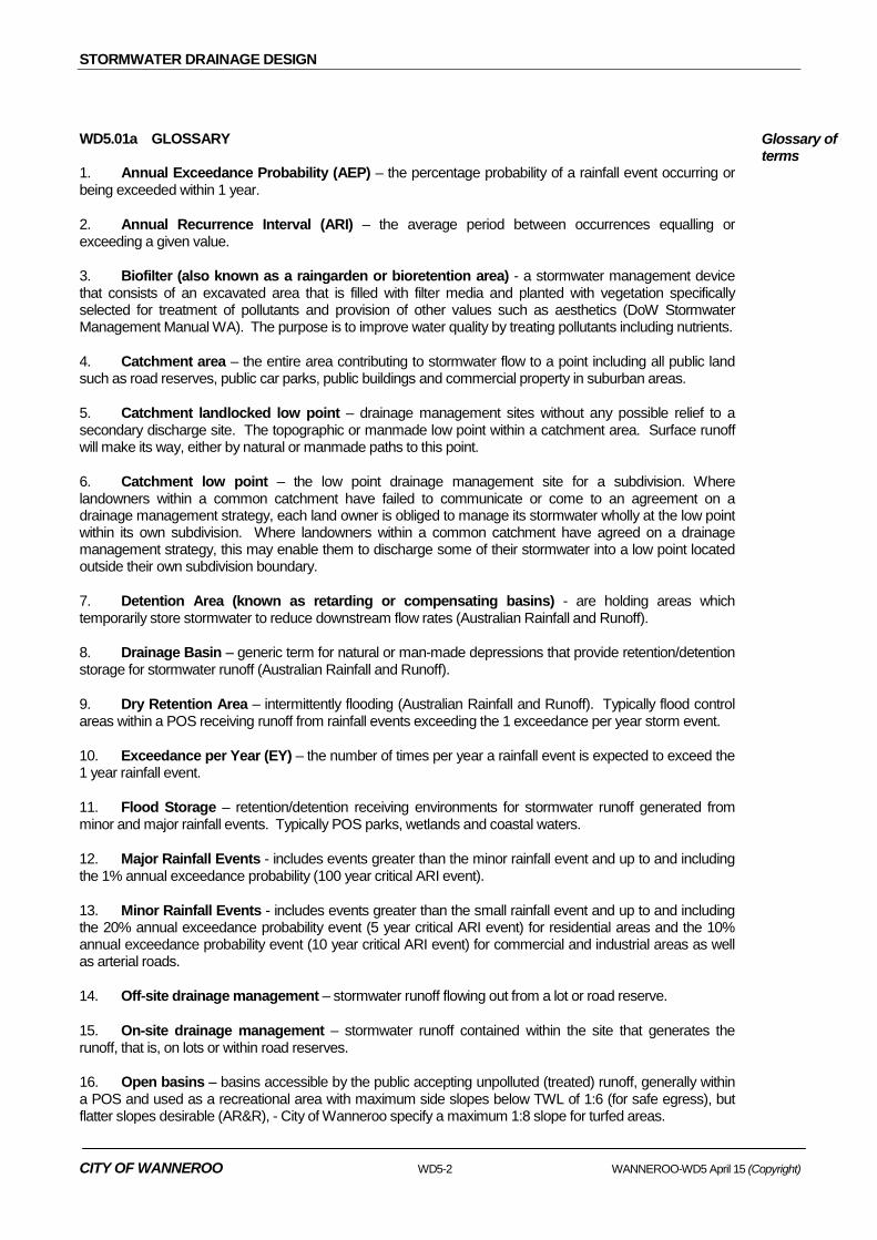
WD5.01a GLOSSARY 1. Annual Exceedance Probability (AEP) – the percentage probability of a rainfall event occurring or being exceeded within 1 year.
2. Annual Recurrence Interval (ARI) – the average period between occurrences equalling or exceeding a given value.
3. Biofilter (also known as a raingarden or bioretention area) - a stormwater management device that consists of an excavated area that is filled with filter media and planted with vegetation specifically selected for treatment of pollutants and provision of other values such as aesthetics (DoW Stormwater Management Manual WA). The purpose is to improve water quality by treating pollutants including nutrients.
4. Catchment area – the entire area contributing to stormwater flow to a point including all public land such as road reserves, public car parks, public buildings and commercial property in suburban areas.
5. Catchment landlocked low point – drainage management sites without any possible relief to a secondary discharge site. The topographic or manmade low point within a catchment area. Surface runoff will make its way, either by natural or manmade paths to this point.
6. Catchment low point – the low point drainage management site for a subdivision. Where landowners within a common catchment have failed to communicate or come to an agreement on a drainage management strategy, each land owner is obliged to manage its stormwater wholly at the low point within its own subdivision. Where landowners within a common catchment have agreed on a drainage management strategy, this may enable them to discharge some of their stormwater into a low point located outside their own subdivision boundary.
7. Detention Area (known as retarding or compensating basins) - are holding areas which temporarily store stormwater to reduce downstream flow rates (Australian Rainfall and Runoff).
8. Drainage Basin – generic term for natural or man-made depressions that provide retention/detention storage for stormwater runoff (Australian Rainfall and Runoff).
9. Dry Retention Area – intermittently flooding (Australian Rainfall and Runoff). Typically flood control areas within a POS receiving runoff from rainfall events exceeding the 1 exceedance per year storm event.
10. Exceedance per Year (EY) – the number of times per year a rainfall event is expected to exceed the 1 year rainfall event.
11. Flood Storage – retention/detention receiving environments for stormwater runoff generated from minor and major rainfall events. Typically POS parks, wetlands and coastal waters.
12. Major Rainfall Events - includes events greater than the minor rainfall event and up to and including the 1% annual exceedance probability (100 year critical ARI event).
13. Minor Rainfall Events - includes events greater than the small rainfall event and up to and including the 20% annual exceedance probability event (5 year critical ARI event) for residential areas and the 10% annual exceedance probability event (10 year critical ARI event) for commercial and industrial areas as well as arterial roads.
14. Off-site drainage management – stormwater runoff flowing out from a lot or road reserve.
15. On-site drainage management – stormwater runoff contained within the site that generates the runoff, that is, on lots or within road reserves.
16. Open basins – basins accessible by the public accepting unpolluted (treated) runoff, generally within a POS and used as a recreational area with maximum side slopes below TWL of 1:6 (for safe egress), but flatter slopes desirable (AR&R), - City of Wanneroo specify a maximum 1:8 slope for turfed areas.
Glossary of terms
CITY OF WANNEROO WD5-2 WANNEROO-WD5 April 15 (Copyright)

STORMWATER DRAINAGE DESIGN
17. Restricted POS - Any POS land encumbered by other policy or land administration factors including drainage infrastructure that impacts on the public usability of land.
18. Retention area – areas that prevent rainfall runoff from being discharged into receiving water bodies by holding it in a storage area. The water may then infiltrate into groundwater, evaporate or be removed by evapotranspiration of vegetation (DoW Stormwater Management Manual WA).
19. Sedimentation trap – a structure designed to intercept and retain sediment transported by water flow (DoW Stormwater Management Manual WA).
20. Small Rainfall Events - includes events up to and including the 1 exceedance per year event which requires runoff management for up to 15mm rainfall depth from constructed impervious areas other than roofs which require management for up to 10mm rainfall depth in the City of Wanneroo. See DoW “Decision Process for Stormwater Management”.
21. Staged development catchment area – when only a portion of a common catchment area is being developed at a particular time, the drainage strategy for the whole catchment should be determined. Where landowners of adjoining parcels of land within this catchment area fail to communicate or agree on a strategy, each land owner will be required to manage its stormwater wholly within its subdivision.
22. Sump – a fenced basin with no public access, accepting polluted (untreated) runoff, having side slopes steeper than 1:6 up to 1:1.5 and a maximum depth of 6.0m.
23. Swale - a drainage interception and conveyance system with relatively gentle side slopes generally maximum 1:6 (except for verge swale max 1:3 where depth < 0.5m), longitudinal slope of 1.0% to 4.0% and shallow flow depths (DoW Stormwater Management Manual WA).
24. Vegetated Swale – a swale with vegetation covering the side slopes and base. Vegetation can range from grass to native sedges and shrubs depending on hydraulic and landscape requirements (DoW Stormwater Management Manual WA).
25. Wet Detention Basin – incorporates a permanent pond (Australian Rainfall and Runoff).
Wetlands – areas of seasonally, intermittently or permanently waterlogged or inundated land whether natural or otherwise, including lakes, sumplands, playas, damplands, floodplains, barlkarras, palusplains, paluslopes, palusmonts or tidal flats (DoW Stormwater Management Manual WA).
WD5.02 STORMWATER MANAGEMENT OBJECTIVES AND CRITERIA
1. Stormwater management systems should mimic natural hydrological processes as much as possible. Stormwater flows resulting from development works should be managed so as to be similar to pre-development flows.
2. The objectives of the stormwater management approach are as follows:
a) Small rainfall event constructed impervious area runoff should be retained/detained on-site at the runoff source in structures/systems to manage water quality and to maintain sensitive receiving environment form and hydrology.
b) Minor rainfall event constructed impervious area runoff should be managed so as to maintain serviceability, amenity and safety of transport networks and public open spaces.
c) Major rainfall event flood levels, peak flow rates and flood storage volumes are to be maintained at pre-development levels for catchments that do not have a published catchment plan. No flooding of building habitable floor levels as well as utility facility floor levels should be allowed to occur.
Mimic natural hydraulic processes
Objectives
Small rainfall event
Minor rainfall event
Major rainfall event
WANNEROO-WD5 April 15 (Copyright) WD5-3 CITY OF WANNEROO
STORMWATER DRAINAGE DESIGN
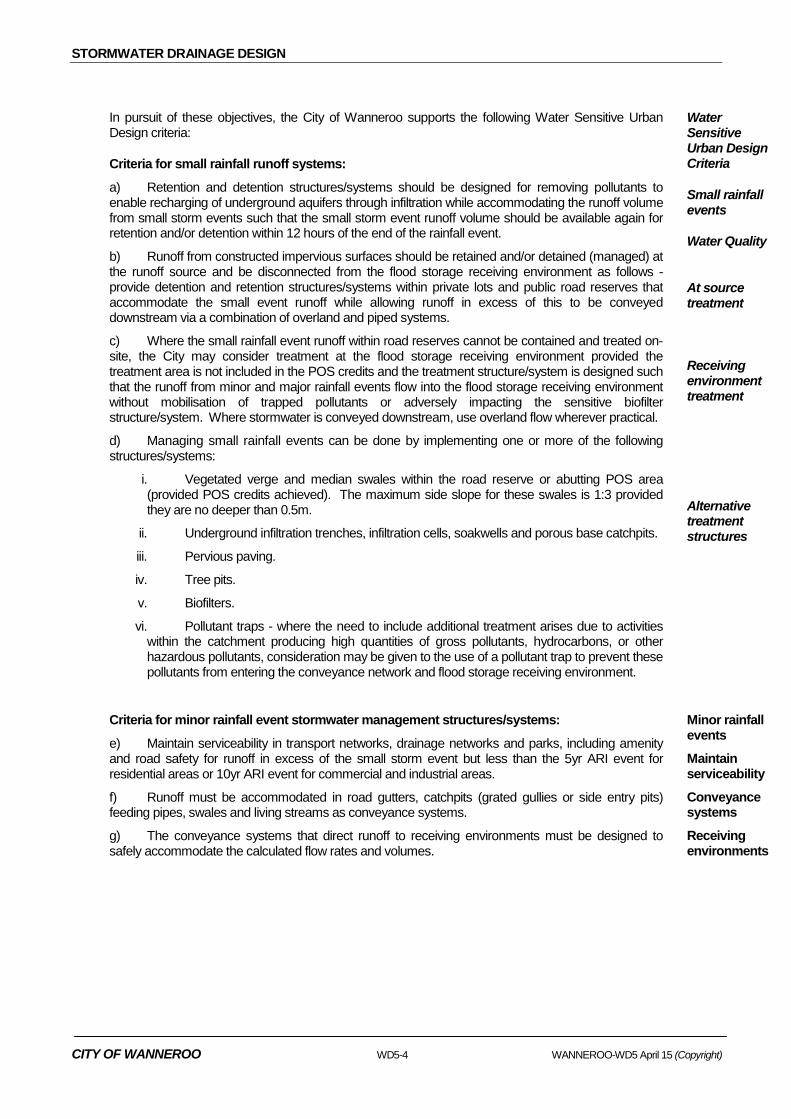
In pursuit of these objectives, the City of Wanneroo supports the following Water Sensitive Urban Design criteria:
Criteria for small rainfall runoff systems:
a) Retention and detention structures/systems should be designed for removing pollutants to enable recharging of underground aquifers through infiltration while accommodating the runoff volume from small storm events such that the small storm event runoff volume should be available again for retention and/or detention within 12 hours of the end of the rainfall event.
b) Runoff from constructed impervious surfaces should be retained and/or detained (managed) at the runoff source and be disconnected from the flood storage receiving environment as follows - provide detention and retention structures/systems within private lots and public road reserves that accommodate the small event runoff while allowing runoff in excess of this to be conveyed downstream via a combination of overland and piped systems.
c) Where the small rainfall event runoff within road reserves cannot be contained and treated on-site, the City may consider treatment at the flood storage receiving environment provided the treatment area is not included in the POS credits and the treatment structure/system is designed such that the runoff from minor and major rainfall events flow into the flood storage receiving environment without mobilisation of trapped pollutants or adversely impacting the sensitive biofilter structure/system. Where stormwater is conveyed downstream, use overland flow wherever practical.
d) Managing small rainfall events can be done by implementing one or more of the following structures/systems:
i. Vegetated verge and median swales within the road reserve or abutting POS area (provided POS credits achieved). The maximum side slope for these swales is 1:3 provided they are no deeper than 0.5m.
ii. Underground infiltration trenches, infiltration cells, soakwells and porous base catchpits.
iii. Pervious paving.
iv. Tree pits.
v. Biofilters.
vi. Pollutant traps - where the need to include additional treatment arises due to activities within the catchment producing high quantities of gross pollutants, hydrocarbons, or other hazardous pollutants, consideration may be given to the use of a pollutant trap to prevent these pollutants from entering the conveyance network and flood storage receiving environment.
Water Sensitive Urban Design Criteria
Small rainfall events
Water Quality
At source treatment
Receiving environment treatment
Alternative treatment structures
Criteria for minor rainfall event stormwater management structures/systems:
e) Maintain serviceability in transport networks, drainage networks and parks, including amenity and road safety for runoff in excess of the small storm event but less than the 5yr ARI event for residential areas or 10yr ARI event for commercial and industrial areas.
f) Runoff must be accommodated in road gutters, catchpits (grated gullies or side entry pits) feeding pipes, swales and living streams as conveyance systems.
g) The conveyance systems that direct runoff to receiving environments must be designed to safely accommodate the calculated flow rates and volumes.
Minor rainfall events
Maintain serviceability
Conveyance systems
Receiving environments
CITY OF WANNEROO WD5-4 WANNEROO-WD5 April 15 (Copyright)

STORMWATER DRAINAGE DESIGN
Criteria for major rainfall event management:
h) Flood levels, peak flow rates and floodplain storage volumes are to be maintained at pre-development levels for catchments that do not have a water management plan.
i) Planners and designers must produce subdivisional lot layouts that accommodate major storm event overland escape routes through the road network system down to receiving environments, such as parks, wetlands and sumps, without impacting on private properties and buildings.
j) Residential, commercial and industrial building habitable floor levels are constructed at least 300mm above the major rainfall event flood level of the urban drainage system and at least 500mm above the flood level of adjacent waterways and land locked flood storage receiving environments (1000mm for special facilities such as Western Power infrastructure, emergency services facilities and schools).
k) Roads in fill are constructed such that a 100mm freeboard is provided between the ponding level of water in the road and the highpoint in the verge footpath.
Major rainfall events
Maintain pre-development
Overland escape routes
Habitable floor levels Elevated road freeboard
WD5.03 REFERENCE AND SOURCE DOCUMENTS
(a) Council Policies LPP 4.1 Wetlands LPP 4.3 Public Open Space LPP 4.4 Urban Water Management
(b) Council Specifications D5 - Stormwater Drainage Design C220 - Stormwater Drainage - General C221 - Pipe Drainage C222 - Precast Box Culverts C223 - Drainage Structures C224 - Open Drains
(c) Australian Standards AS 1254 - Unplasticised PVC (uPVC) pipes and fittings for stormwater or
surface water applications. AS 2032 - Code of practice for installation of uPVC pipe systems. AS 3725 - Loads on buried concrete pipes. AS 4058 - Precast concrete pipes. AS 4139 - Fibre reinforced concrete pipes and fittings.
(d) Standard Drawings TS 03-1-0 - Outlet Structure Details TS 03-2-0 - Headwall Details TS 03-3-0 - Junction Pit Construction Details TS 03-4-0 - Sump and Sump Outfall Details TS 03-5-0 - Gully / Junction Pit Modified - Trapped and Untrapped Gullies TS 03-6-0 - At Grade / Table Drain – Inlet / Outlet Structure TS 03-7-0 - Side Entry Pit – Type 1 (Plain Slab) TS 03-8-0 - Side Entry Pit – Type 2 (Deflector Slab) TS 03-9-0 - Side Entry Pit – Type 3 (Combination Side Entry Pit and Grated Entry) TS 03-10-0 - Side Entry Pit – Type 4 (Combination Side Entry Pit and Flush Entry) TS 01-2-0 - Sump Security TS 01-6-0 - Drainage Sump Site Sign
WANNEROO-WD5 April 15 (Copyright) WD5-5 CITY OF WANNEROO

STORMWATER DRAINAGE DESIGN
HYDROLOGY
WD5.04 DESIGN RAINFALL DATA
1. Generally designers can develop their own IFD tables as outlined in the Australian Rainfall and Run-off. Typical IFD rainfalls for the Perth station are typically used throughout the City (see below).
I-F-D Relationships
Table 1 Rainfall Intensity-Frequency-Duration (IFD) mm/hr Duration Average Storm Return Interval
1yr 5yr 10yr 50yr 100yr 6 min 54.8 95.1 111 168 197 10 min 43.8 74.9 87.3 130 151 30 min 24.2 39.8 45.6 65.5 75.5 1 hour 15.96 25.51 28.63 40.03 45.6 10 hour 3.57 5.52 6.25 8.42 9.52 24 hour 2.02 3.16 3.54 4.89 5.54 48 hour 1.26 2.01 2.28 3.20 3.65 72 hour 0.94 1.50 1.71 2.43 2.78
2. Australian Rainfall and Runoff preferred terminology – Annual Exceedance Probability (AEP)
AEP (%) ARI (Years)
63 1:1
18 1:5
10 1:10
1 1:100
WD5.05 CATCHMENT AREA
1. All sub-dividers with land in a common catchment area have a joint responsibility to ensure that the whole catchment area (including arterial roads) will be served by an effective drainage system. The total catchment area shall include all public land such as road reserves, public car parks, public buildings etc. Stormwater drainage from commercial properties in suburban areas is to be incorporated in the drainage system.
Catchment Extent
2. When only a portion of a catchment is being developed at a particular time (staged development) the drainage strategy for the whole subdivisional catchment should be determined. Subdividers are responsible for negotiating and arranging their own cost sharing arrangements with respect to stormwater drainage. Where landowners of adjoining parcels of land within the catchment area fail to communicate or agree on a drainage strategy, each subdivider will be required to dispose of its stormwater drainage wholly within its subdivision.
3. All stormwater runoff from constructed impervious surfaces within a private property lot should be included as the catchment for the lot (note roof catchment is managed via the Building Code of Australia).
4. The sub-divider shall provide, at their cost, the necessary pipework and system capacity to carry stormwater from arterial road reserves. Drainage pits, and manholes shall be provided at the edge of the arterial road reserve to serve as connection points between the sub-division drainage system and the arterial road drainage system. Council will be responsible for building the pipework in the arterial road reserve when the development of the road is considered to warrant it.
Staged Development
Private property
Arterial road reserves
CITY OF WANNEROO WD5-6 WANNEROO-WD5 April 15 (Copyright)
STORMWATER DRAINAGE DESIGN
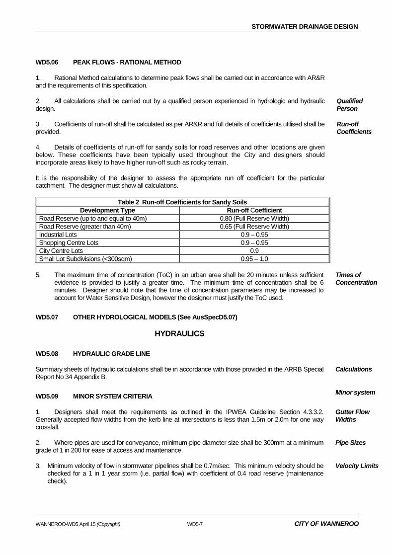
WD5.06 PEAK FLOWS - RATIONAL METHOD
1. Rational Method calculations to determine peak flows shall be carried out in accordance with AR&R and the requirements of this specification.
2. All calculations shall be carried out by a qualified person experienced in hydrologic and hydraulic design.
Qualified Person
3. Coefficients of run-off shall be calculated as per AR&R and full details of coefficients utilised shall be provided.
Run-off Coefficients
4. Details of coefficients of run-off for sandy soils for road reserves and other locations are given below. These coefficients have been typically used throughout the City and designers should incorporate areas likely to have higher run-off such as rocky terrain.
It is the responsibility of the designer to assess the appropriate run off coefficient for the particular catchment. The designer must show all calculations.
Table 2 Run-off Coefficients for Sandy Soils
Development Type Run-off Coefficient Road Reserve (up to and equal to 40m) 0.80 (Full Reserve Width) Road Reserve (greater than 40m) 0.65 (Full Reserve Width) Industrial Lots 0.9 – 0.95 Shopping Centre Lots 0.9 – 0.95 City Centre Lots 0.9 Small Lot Subdivisions (<300sqm) 0.95 – 1.0
5. The maximum time of concentration (ToC) in an urban area shall be 20 minutes unless sufficient evidence is provided to justify a greater time. The minimum time of concentration shall be 6 minutes. Designer should note that the time of concentration parameters may be increased to account for Water Sensitive Design, however the designer must justify the ToC used.
Times of Concentration
WD5.07 OTHER HYDROLOGICAL MODELS (See AusSpecD5.07)
HYDRAULICS
WD5.08 HYDRAULIC GRADE LINE
Summary sheets of hydraulic calculations shall be in accordance with those provided in the ARRB Special Report No 34 Appendix B.
Calculations
WD5.09 MINOR SYSTEM CRITERIA Minor system
1. Designers shall meet the requirements as outlined in the IPWEA Guideline Section 4.3.3.2. Generally accepted flow widths from the kerb line at intersections is less than 1.5m or 2.0m for one way crossfall.
Gutter Flow Widths
2. Where pipes are used for conveyance, minimum pipe diameter size shall be 300mm at a minimum grade of 1 in 200 for ease of access and maintenance.
Pipe Sizes
3. Minimum velocity of flow in stormwater pipelines shall be 0.7m/sec. This minimum velocity should be checked for a 1 in 1 year storm (i.e. partial flow) with coefficient of 0.4 road reserve (maintenance check).
Velocity Limits
WANNEROO-WD5 April 15 (Copyright) WD5-7 CITY OF WANNEROO

STORMWATER DRAINAGE DESIGN
4. For all low points, a 100 year critical storm event should be checked with the system to ensure that there is sufficient capacity in the road drainage minor system to cope with the storm event, without flooding properties. Planners and designers are encouraged to produce subdivisional lot layouts that accommodate major storm events, overland escape routes through the road network system down to secondary storage areas, like parks and reserves, without impacting on private properties and buildings. The size and inundation levels of the receiving environment will need to be checked to ensure that there is sufficient storage capacity at these locations.
Low Points
5. Low points adjacent to residential properties are discouraged and designers should ensure that there are overflow surface runoff routes to parks or other areas which will not cause localised flooding.
At least one set of double side entry pits (SEPs) shall be provided at all low points within a catchment. Notwithstanding, the drainage system must be checked in accordance with the item 4 above. Additional SEPs may be required to capture the surface runoff. Grated gulley pits have the advantage of restricting gross pollutants from entering the piped system, but should be avoided at trapped low points where the grating may become blocked with debris resulting in flooding.
SEPs at Low Points
WD5.10 PITS Pits
1. Inlet pits shall be spaced so that the gutter flow width is limited in accordance with this specification and so that the inlet efficiency is not affected by adjacent inlet openings.
Spacing
2. Side entry pits are to be designed such that there is minimum interference to future crossovers, pedestrian/cyclist ramps and at intersections. Preference will be given to the location of side entry pits at a point approximately 8 metres from the side boundary or centrally located between lot boundaries (allowing for future crossovers).
3. For lots having a frontage of less than 18m, grated gulley pits should be used so as not to restrict crossover access.
Side Entry Pits
Grated Gulley Pits
4. Where gullies and side entry pits are connected to the main-line via junction manholes, the minimum connection pipe diameter should be 300mm.
On-line Pits
5. Where designers choose to incorporate SEPs directly into main-line pipelines, these shall only be used at the upper end of the catchment where small diameter pipes are used. SEPs shall not be connected directly into pipes greater than 600mm.
Side Entry Pits & Main-lines
Where SEPs are permitted to be placed over the main line, the following conditions shall apply:
• Pit depth shall be limited to a maximum of 1.2 metres from the road surface to the outlet invert. The City may consider depths up to 1.8 metres in specific circumstances where it is justified. These need to be discussed and agreed to with the City prior to finalising the design.
• The throat depth at the kerb entry to the pit shall be 95mm (+15/-15mm).
• The SEP access cover is to be secured against removal by unauthorised personnel.
6. Pits shall meet the requirements as laid out in the City’s Standard Drawings. Standard Drawings
CITY OF WANNEROO WD5-8 WANNEROO-WD5 April 15 (Copyright)

STORMWATER DRAINAGE DESIGN
7. Step irons shall be constructed for all pits and manholes where the difference in levels between the base and the surface level exceeds 1.0 metre.
Step Iron requirements
8. Inlet pits (not located on main lines) shall be designed as infiltration devices unless the soil is impervious which would prevent infiltration. Infiltration pits must be designed for sediment and gross pollutant removal by eduction, restricting the mobilisation of trapped pollutants from high volume flows and minimising standing water due to clogging of the porous base.
Infiltration Pits
WD5.11 HYDRAULIC LOSSES
1. The pressure change co-efficient “Ke” shall be determined from the appropriate charts given in ARRB Special Report No 34 or equivalent source. All sources of coefficients used in calculations shall be provide to Council with design summary schedules.
Pit Losses
2. Reductions in “Ke” due to benching are allowable and designers are to provide Council with information concerning the source of coefficients used.
3. Computer program default pressure change co-efficient “Ke” shall not be acceptable unless they are consistent with those from the charts in ARRB special report No 34 or equivalent source.
The chart used and relevant co-efficients for determining “Ke” value from that chart shall be noted on the hydraulic summary sheet provided for plan checking and included on the final design drawings.
Computer Programme Default “Ke”
4. Bends may be permissible in certain circumstances and discussions with Council regarding their use is required prior to detailed design. Appropriate values of pit pressure change co-efficient at bends are to be provided in the hydraulic summary sheet provided for plan checking and included on the final design drawings.
Bend Losses
5. Where possible design should try to avoid clashes between services. However, where unavoidable clashes occur with existing sewer mains, then the pressure change co-efficient Kp shall be determined from the appropriate charts. All sources of coefficients used in calculations shall be provided to Council with design summary schedules.
Service Entry Losses
6. Construction of a junction without a structure should be avoided where possible. Permission to do this is required by Council prior to detailed design. Where this is unavoidable the pressure change co-efficients Ku, for the upstream pipe and Ki, for the lateral pipe, shall be determined from the chart given in the ARRB Special Report No 34.
Pipe Junction Losses
WD5.12 OPEN CHANNELS
Maximum side slopes on grassed lined, unfenced open channels shall be 1 in 4, with a preference given to 1 in 6 side slopes, channel inverts shall generally have minimum cross slopes of 1 in 20.
Side Slopes
WD5.13 MAJOR SYSTEM CRITERIA
1. Freeboard requirements for floor levels and levee bank levels from flood levels in open channels, roadways and major event flow-paths are given below:
Generally:
Freeboard
a) Residential, commercial and industrial building habitable floor levels must be constructed with at least 300mm freeboard above the major rainfall event flood level of the urban drainage system and at least 500mm above the flood level of abutting waterways and land locked flood storage receiving environments.
Freeboard to floor levels
b) Where the road is in fill or overtopping of kerbs and flow through properties may occur a 100mm freeboard shall be provided between the ponding level of water in the road and the high point in the
Freeboard containment for elevated roads
WANNEROO-WD5 April 15 (Copyright) WD5-9 CITY OF WANNEROO
STORMWATER DRAINAGE DESIGN
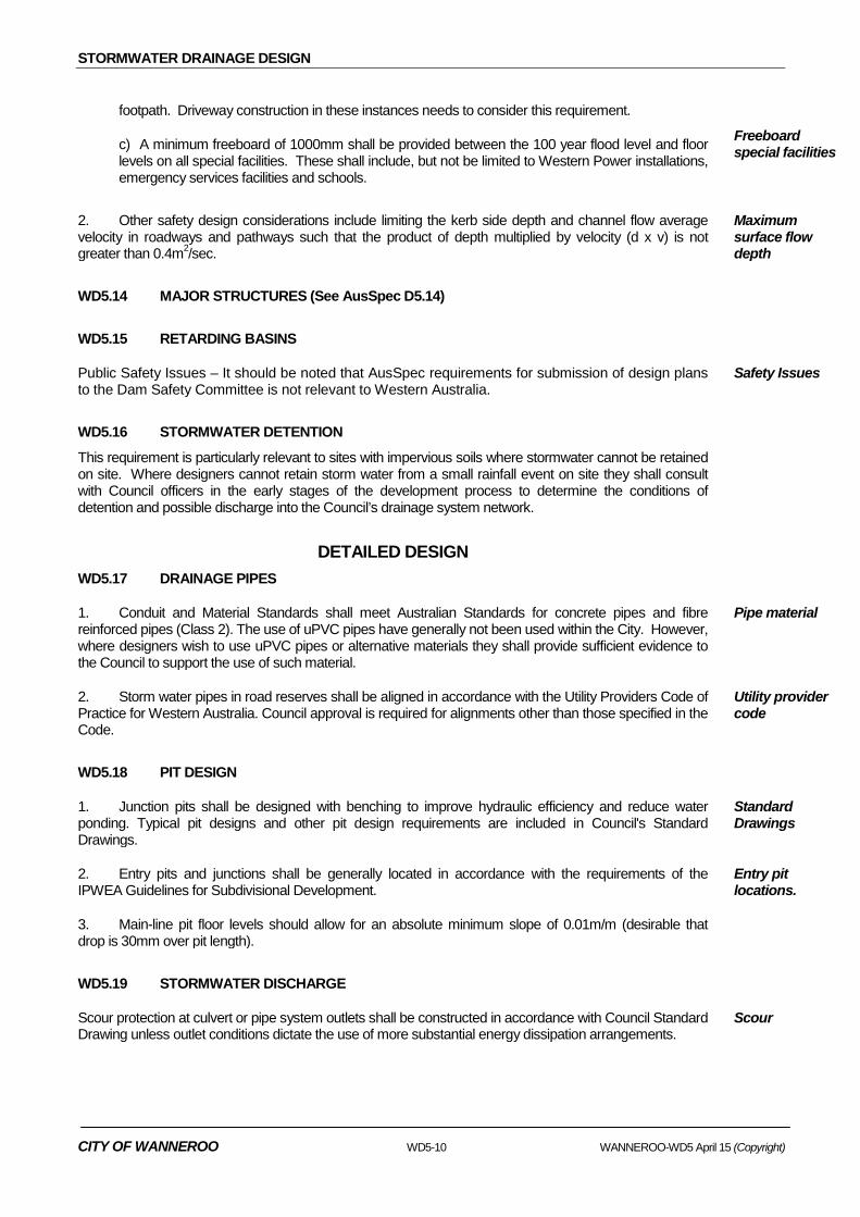
footpath. Driveway construction in these instances needs to consider this requirement.
c) A minimum freeboard of 1000mm shall be provided between the 100 year flood level and floor levels on all special facilities. These shall include, but not be limited to Western Power installations, emergency services facilities and schools.
Freeboard special facilities
2. Other safety design considerations include limiting the kerb side depth and channel flow average velocity in roadways and pathways such that the product of depth multiplied by velocity (d x v) is not greater than 0.4m2/sec.
Maximum surface flow depth
WD5.14 MAJOR STRUCTURES (See AusSpec D5.14)
WD5.15 RETARDING BASINS
Public Safety Issues – It should be noted that AusSpec requirements for submission of design plans to the Dam Safety Committee is not relevant to Western Australia.
Safety Issues
WD5.16 STORMWATER DETENTION
This requirement is particularly relevant to sites with impervious soils where stormwater cannot be retained on site. Where designers cannot retain storm water from a small rainfall event on site they shall consult with Council officers in the early stages of the development process to determine the conditions of detention and possible discharge into the Council’s drainage system network.
DETAILED DESIGN
WD5.17 DRAINAGE PIPES
1. Conduit and Material Standards shall meet Australian Standards for concrete pipes and fibre reinforced pipes (Class 2). The use of uPVC pipes have generally not been used within the City. However, where designers wish to use uPVC pipes or alternative materials they shall provide sufficient evidence to the Council to support the use of such material.
Pipe material
2. Storm water pipes in road reserves shall be aligned in accordance with the Utility Providers Code of Practice for Western Australia. Council approval is required for alignments other than those specified in the Code.
Utility provider code
WD5.18 PIT DESIGN
1. Junction pits shall be designed with benching to improve hydraulic efficiency and reduce water ponding. Typical pit designs and other pit design requirements are included in Council's Standard Drawings.
Standard Drawings
2. Entry pits and junctions shall be generally located in accordance with the requirements of the IPWEA Guidelines for Subdivisional Development.
Entry pit locations.
3. Main-line pit floor levels should allow for an absolute minimum slope of 0.01m/m (desirable that drop is 30mm over pit length).
WD5.19 STORMWATER DISCHARGE
Scour protection at culvert or pipe system outlets shall be constructed in accordance with Council Standard Drawing unless outlet conditions dictate the use of more substantial energy dissipation arrangements.
Scour
CITY OF WANNEROO WD5-10 WANNEROO-WD5 April 15 (Copyright)
STORMWATER DRAINAGE DESIGN
WD5.20 MISCELLANEOUS (See AusSpec D5.21)
PRIVATE PROPERTY
WD5.21 PRIVATE PROPERTY STORMWATER MANAGEMENT
1. The catchment is to include all stormwater runoff from constructed impervious surfaces within the lot (note roof catchment is managed via the Building Code of Australia).
2. Residential lots having a single dwelling must manage small rainfall event runoff from constructed impervious surfaces within the lot.
3. Small rainfall event runoff storage can utilise a combination of detention ponding in areas such as surfaced driveways and car parks plus retention storage in the form of surface swales and underground soakwells. Soakwell sizing may be based on 1cum per 60sqm of constructed impervious surface runoff area. The use of detention ponding is subject to adequate containment being demonstrated and the maximum water depth not exceeding 200mm in areas accessed by pedestrians.
4. Group housing lots and industrial lots must, in addition to small rainfall events, manage minor and major rainfall event runoff on-site as per the stormwater management requirements detailed for public property in this specification.
5. Generally stormwater from private lots shall not be permitted to enter the Council’s stormwater drainage system. In special circumstances where, due to the impervious nature of the natural ground or the occurrence of a high water table, it is demonstrated that it is impractical to manage all of the stormwater runoff from constructed impervious surfaces on site, the Council may grant approval for some of the water to be discharged into the Council storm water drainage system. This will be dependent upon as much of the runoff as practical being managed on the lot and the existing road drainage system being able to accommodate the additional flows.
Use overland flow for runoff from private properties to the Council road drainage system where practical. If overland flow is impractical, piped connection to the Council’s road drainage system is subject to the following requirements:
a) All pipe inlets, including roof and subsoil pipes, shall where possible, enter the main pipe system at junction pits.
b) These shall be finished off flush and if a junction has to be added which is larger than 150mm, then a junction pit shall be built at this location in accordance with this specification.
c) For smaller inlets, the drainage pipes may be broken into to allow interconnection with the main-line. In this case the sideline shall be finished flush with and be grouted into the main-line in accordance with the requirements as detailed in the Water Corporation’s specifications for small inlet connections.
Catchment
Single dwelling private lots
On-site retention / detention
Group housing, industrial and commercial lots
Lot surcharge off-site
WANNEROO-WD5 April 15 (Copyright) WD5-11 CITY OF WANNEROO

STORMWATER DRAINAGE DESIGN
FLOOD STORAGE RECEIVING ENVIRONMENT
WD5.22 WATER QUALITY
1. Small rainfall event runoff must not enter off-site flood storage receiving environments unless the water has been treated.
Where it has been demonstrated that site conditions do not allow for the full runoff volume from small rainfall events to be managed on-site, manage as much as practical on-site, then management of the remaining volume off-site within the POS may be accepted, subject to meeting the following criteria:
a) There is no reduction in POS amenities.
b) The subdivision complies with the POS credit requirements as stated in Liveable Neighbourhoods (the treatment area for managing small rainfall event runoff within the POS will receive 0% POS credits).
c) The treatment area (biofilter or vegetated swale) must not be located within the receiving environment minor or major rainfall event flood storage areas.
d) The treatment area is designed such that the runoff from minor and major rainfall events do not mobilise trapped pollutants or adversely impact the sensitive biofiltration system.
e) The depth below top water level does not exceed 500mm.
f) The treatment area side slopes do not exceed 1:3.
g) The treatment area is planted and landscaped to restrict public access.
h) The treatment area empties within 12 hours after the rainfall event.
Small rainfall event
Off-site management
WD5.23 INFILTRATION
1. Infiltration properties at a site depend very much on the hydraulic conductivity of the soil which vary from site to site, therefore when considering infiltration rates, site investigation and infiltration modelling are necessary for appropriate storage area sizing.
2. The City accepts infiltration in calculating the long duration (minor and major rainfall events) stormwater management volumes for the sizing of stormwater retention facilities subject to the following:
a) Field measurements of soil conductivity (infiltration tests) shall be undertaken by a suitably qualified person to determine the depth to groundwater and the hydraulic properties of the soil.
b) Hydraulic properties of the soil shall be determined in situ at the location of the proposed infiltration system and measurements taken at the depth corresponding to the proposed base elevation of the infiltration facility. Borehole soil samples may be taken for testing in a laboratory where the required depth is too deep for field testing, tests to be undertaken in accordance with recognized standards (examples include: ASTM D3385-09 Standard test method for infiltration rate of soils in the field using the Double Ring Infiltrometer, AS/NZS 1547:2012 appendix G soil permeability measurement constant head test).
c) Measured field test of point soil hydraulic conductivity being adjusted by applying for soil type. Soil moderation factors: sand 0.5; sandy clay 1.0; medium and heavy clay 2.0 (Engineers Australia, 2006) to estimate aerial soil hydraulic conductivity.
d) Where long term or lifespan hydraulic conductivity is used, the soil moderation factor is 1.0 and the hydraulic conductivity is influenced by clogging rates. Clogging rates depend on the amount of directly connected impervious surfaces, the type of infiltration system and the maintenance regime. Clogging factors: grassed or vegetated infiltration basins 0.5, non-vegetated infiltration basins and sumps 0.2 to 0.5, pervious paving 0.2 (John Argue, 2004).
Hydraulic conductivity
Field tests to determine Infiltration Rates
Soil Moderation factor
Clogging factor
CITY OF WANNEROO WD5-12 WANNEROO-WD5 April 15 (Copyright)
STORMWATER DRAINAGE DESIGN
e) Soil profiling by a geotechnical engineer must be provided to a depth of 4.0 metres or to a depth confirming impervious rock whichever is less.
f) The depth to water table shall be confirmed based on monitoring of water table bores installed at the site, correlated to nearby Department of Water bore/s to obtain an estimate of the Maximum Groundwater Level (MGL).
3. The appropriate method for analysis of infiltration systems depends on the depth to water table.
a) The deep water table approach is suitable where the water table is greater than 4.0 metres below the ground surface. Use of PCSUMP (deep water table option) or the spreadsheet model INFIL is recommended.
b) The shallow water table approach is suitable where the water table is within 4.0 metres of the ground surface. Use of PCSUMP (shallow water table option) or MODRET is recommended.
4. Water table separation – the invert level of flood storage areas is to be set at least 0.3 metres above the MGL.
WD5.24 NATURAL WATER BODIES AND WETLAND RECEIVING ENVIRONMENTS
The City will not accept small rainfall event runoff into wetlands.
The City will accept minor and major rainfall event runoff into wetlands where it satisfies the following criteria:
1. The preparation of an Urban Water Management Plan (UWMP) demonstrating onsite management and treatment of all small rainfall events.
2. Stormwater should not be discharged directly into wetlands and should not bypass vegetated buffers around wetlands.
3. Runoff from minor and major rainfall events are to reach wetlands classified for conservation category or resource enhancement category via vegetated overland flowpaths.
4. Maintain pre-development surface water flow rates, runoff volumes and flood level and shallow groundwater recharge rates, unless otherwise established in an approved management strategy or plan and subject to the advice of the City and Department of Parks and Wildlife (DPaW) or Department of Water (DoW).
5. The use of appropriate water sensitive urban design criteria.
Soil profile
Water table depth
Infiltration analysis
Minimum water table separation
Unacceptable discharge
Accepting runoff from minor and major rainfall events
WD5.25 PUBLIC OPEN SPACE RECEIVING ENVIRONMENTS
The City will not accept small rainfall event runoff into a POS.
1. Flood storage areas within a POS will be dry for the majority of time and should be designed as an amenity for public use (nature, recreation or sport). Designers shall consider the health and safety issues associated with the direct discharge of stormwater runoff from minor and major rainfall events into areas accessible by the public.
2. Areas containing drainage infrastructure (such as pipe discharge outlets and energy dissipation structures) and areas where surface flows are such that the product of depth multiplied by velocity exceeds 0.4m2/sec shall be treated as restricted Public Open Space (POS) for purposes of POS liability. Restricted POS is limited to a maximum of 2.0% of the gross sub divisible area (Liveable Neighbourhoods).
3. Flood storage areas in a POS having public access must meet the following criteria:
a) Side slopes below TWL are no steeper than 1:6.
b) Retaining walls are not allowed within the flood storage area where the top of the wall falls below Top Water Level (TWL). For the purposes of this requirement, TWL is taken as the discharge hydraulic grade line at the flood storage area or the major rainfall event flood level.
Integration of POS functions
Restricted POS
Criteria for public access
WANNEROO-WD5 April 15 (Copyright) WD5-13 CITY OF WANNEROO

STORMWATER DRAINAGE DESIGN
c) The maximum allowable water depth below TWL must not exceed 0.9m for events greater than the 1:1 ARI event up to a 1:10 ARI and 1.2m for events over 1:10 ARI and up to a 1:100 ARI event.
d) Stormwater runoff entering the flood storage area must not contain pollutants that pose a risk to the safety of the public.
4. The maximum length of time allowed for drainage infiltration areas to empty is as follows for the rainfall events described. This is measured as from the end of the event (DoW Stormwater Management Manual – Structural Controls Table 5).
a. 1:5 ARI = 36 hrs.
b. 1:100 ARI = 84 hrs.
5. Downstream receiving environments should be sized using the retention/detention capacities of upstream receiving environments including private lot soakwells, road verge swales, upstream basins or sumps.
6. Sizing for flood storage areas should be as follows:
a) Flood storage area not at the catchment low point - storage volume to be calculated using measured infiltration to accommodate the minor rainfall event runoff as generated by the 1:5 year ARI critical storm event in residential areas and the 1:10 year ARI critical storm event in industrial and commercial areas. Allow for a minimum berm freeboard of 300mm.
b) Flood storage area at the catchment low point - storage volume to be calculated using measured infiltration to accommodate the major rainfall event runoff as generated by the 1:100 ARI critical storm event. Allow for a minimum berm freeboard of 300mm or 500mm in the case of a trapped landlocked flood storage area.
Basin gradients
Retaining walls
Maximum water depth
Pollutants
Maximum time to empty
Utilising upstream storage capacity
Flood storage sizing
WD5.26 FENCED SUMP RECEIVING ENVIRONMENTS
The City does not support the use of fenced sumps as flood storage receiving environments. However, where as a necessary result of practical and efficient drainage system design from an engineering perspective, a sump is required (for example a temporary flood storage area), the City will consider this option provided the following criteria are met.
1. Fenced sump sites shall be completely enclosed by a security fence of suitable materials to suit the amenity of the area. A lockable gate and access ramp 4 metres wide at maximum grade of 1 in 4 to the sump base shall be provided for maintenance access.
2. In sizing drainage sumps (generally in sandy conditions), the following design factors shall be met: the depth of the sump should be minimised; the maximum practical depth shall be 6.0 metres measured at the deepest point; the minimum width at the base of the sump shall be 4.0 metres to enable satisfactory maintenance vehicle access; and the base of the sump shall have a slope close to zero.
3. The surface area requirement at TWL may be nominally calculated at a minimum rate of 1m2 for each 40m2 of Equivalent Impervious Area draining into the sump. The surface area of the sump shall be measured at a TWL corresponding to the discharge hydraulic grade line at the sump when available or the lowest level of the incoming pipes.
4. Except where it can be demonstrated by a geotechnical assessment, the horizontal clearance from the top of the sump batter to the closest permitted residence location shall not be less than 5 metres. Consideration shall be given to slope stability and the possible ‘saturation collapse’ of loose sand in the geotechnical assessment.
5. In applying the criteria outlined above, the City will take into account the critical nature and the location of the sump site. Where there are overland flow paths and secondary storage areas located adjacent to the sump site, design requirements may be eased. These alternatives should be discussed with the City at the preliminary design stages.
City position
Fencing
Limiting dimensions
Surface area
Offset from buildings
Secondary storage
CITY OF WANNEROO WD5-14 WANNEROO-WD5 April 15 (Copyright)

STORMWATER DRAINAGE DESIGN
6. Downstream receiving environments should be sized using the retention/detention capacities of upstream receiving environments including private lot soakwells, road verge swales and upstream basins or sumps.
7. Sizing sumps where field infiltration test data is available (retention modelling):
a) Sump not at the catchment low point - sump storage to be sized using infiltration capped at 2m/day to accommodate the minor rainfall event runoff as generated by the 1:5 year ARI critical storm event in residential areas and the 1:10 year ARI critical storm event in industrial and commercial areas. Allow for a minimum berm freeboard of 300mm.
b) Catchment low point sump - sump storage to be sized using infiltration capped at 2m/day to accommodate the major rainfall event runoff as generated by the 1:100 ARI critical storm event. Allow for a minimum berm freeboard of 300mm.
c) Landlocked low point sump - sump to be sized for 1330cum storage per hectare of impervious catchment with no allowance for infiltration to accommodate the 24 hour 1:100 year ARI storm event. Where flooding of properties abutting a land locked sump could result from the sump surcharging, the sump must be designed to have a minimum freeboard of 500mm between the TWL and the habitable floor level of buildings on abutting lots.
8. Sizing sumps where field infiltration test data is unavailable (Empirical Sizing):
a) Sump not at the catchment low point - sump storage to be sized with zero infiltration to accommodate the 1:10 year ARI 10 hour rainfall event runoff of 600cum per hectare of EIA and a freeboard of 300mm.
b) Catchment low point sump - sump storage to be sized with zero infiltration to accommodate the 1:100 year ARI 24 hour rainfall event of 1330cum per hectare of EIA and a berm freeboard of 300mm or 500mm between the TWL and the habitable floor level of buildings on abutting lots in the case of a trapped landlocked sump.
Utilising upstream storage capacity
Sizing using infiltration
Sizing empirical basis
ROAD CROSSINGS
WD5.27 APPLICATION
1. The following conditions apply to development works that necessitate the opening up of existing roads as part of the subdivision. These conditions shall be read in conjunction with the Utility Providers Code of Practice for Western Australia.
Code of Practice
2. A written application indicating the exact location and dimensions of the road crossing shall be submitted to Council.
3. All pipes shall be thrust bored across arterial roads unless otherwise authorised in writing by Council. All requests for open trenching across arterial roads shall include data justifying the need for special approval to open trench.
Arterial roads
4. Reinstatement of the surface of roads, vehicle crossings and footpaths shall be undertaken by the contractor in accordance with the City’s specifications immediately following the works or at the request of the City.
Reinstatement
5. A bond for reinstatement works shall be lodged with Council prior to the commencement of the works. This bond relates to an estimate of costs only and actual expenditure incurred will be charged.
Bond
6. Competent contractors may reinstate road crossings within sub-divisional releases, subject to the prior approval of the Council. The work is to be covered in the maintenance period of the sub-divisional release.
WANNEROO-WD5 April 15 (Copyright) WD5-15 CITY OF WANNEROO

STORMWATER DRAINAGE DESIGN
7. Notification shall be given in writing to Council at least forty-eight (48) hours prior to the commencement of work or re-commencement of work after any prolonged cessation of the works.
Residents shall be advised of intended works at least forty-eight (48) hours prior to the commencement of the works.
Notification to Commence
WD5.28 TRAFFIC CONTROL
1. Roads without approved alternative access such as cul-de-sacs shall be kept open to traffic at all times.
Cul-de-sac
2. Applications for permission to close roads shall be forwarded to Council for approval 6 weeks prior to intended road closure. In certain circumstances, public advertisements may be required prior to the proposed closure which may affect the intended closure date. A traffic management plan shall also be submitted for approval.
In certain cases where it is considered that the closure has minimum impact on traffic and public advertisements are not required, approval may be granted in fourteen (14) days.
Notification in writing shall be given at least forty-eight (48) hours prior to the closing of any road to traffic. Such notification shall also be forwarded to the relevant police, public transport and emergency service authorities.
Road closures shall be kept to a minimum and every cut shall be backfilled and made trafficable immediately after pipe laying has been completed.
Closures
The contractor shall make adequate provision for all traffic using the road or footpath and shall erect such barriers, warning signs, etc., as is required under Australian Standards 1742.3.
Site Control
WD5.29 EXCAVATION
1. The road surface shall be cut to provide a clean straight joint prior to the commencement of excavation works. Stockpiling of any excavated materials other than immediately adjacent to the excavation shall be on approved sites only.
Cutting
2. Cultivated lawns shall be removed for the full top width of the excavation by cutting with a sodding machine and the sods neatly stacked in a manner to ensure the maximum possible preservation of the lawn. After completion, such lawns shall be reinstated as near as practicable to its original condition.
Lawns
WD5.30 EMERGENCIES
1. In the event of any irregularities or emergencies occurring, Council must be notified immediately of the problem(s) occurring and the intended remedial action.
Notification
2. Any damages which may occur to Council facilities or private property during the course of the road cutting operations either directly or indirectly, or which may subsequently be evident from the operations thereof, shall be the sole responsibility of the applicant.
Damages
3. The applicant shall be responsible for the repair, replacement, legal claim liability or result that may arise from the road cutting.
Repair Liability
CITY OF WANNEROO WD5-16 WANNEROO-WD5 April 15 (Copyright)

STORMWATER DRAINAGE DESIGN
BACKFILL OF TRENCHES
WD5.31 MATERIALS
1. Backfill material for road crossings shall be entirely of sand or other road pavement material approved by Council to within 300mm of the road surface. The sand shall be free of clay material, vegetable matter, building debris and disused road paving material.
Sub-base
2. The upper 300mm shall consist of crushed limestone or bitumen stabilised limestone, evenly graded, with a maximum spall size of 100mm. The surface shall be sealed with material matching the existing road pavement to the nominated thickness.
Base Course
WD5.32 COMPACTION
1. Before the general backfill of the trench is commenced, all manholes and spaces around the utility installed shall be carefully compacted with hand rammers. The minimum depth of initial hand compaction above the crown of the pipe shall be no less than 150mm.
Hand Compaction
2. Compaction of the remaining backfill shall be in 150mm layers. Compaction shall be achieved by mechanical means with water to a density of not less than 95% of the maximum dry density when tested in accordance with AS 1289 - 1977 (Part E2-1), or at least equal to that of the surrounding undisturbed road.
Sub-base
3. The limestone base course shall be compacted to 95% of the maximum dry density when tested in accordance with AS 1289 - 1977 (Part E2-1). Base Course
4. Measurement using a properly calibrated standard Perth penetrometer would be acceptable or at least equal to that of the surrounding undisturbed road. Penetrometer
WD5.33 VEHICLE CROSSOVERS
1. Materials for backfilling trenches across driveways shall be as for road crossings, with the minimum depth of limestone being 175mm. Material
2. The compaction standard for driveways shall not be less than 92% of the maximum dry density when tested in accordance with AS 1289 - 1977 (Part E2-1), measurement using a properly calibrated standard Perth penetrometer would be acceptable.
Compaction
WD5.34 FOOTPATHS
1. Materials for backfilling trenches across footpaths shall be clean sand or other material approved by Council to be brought up to the full depth of the trench. No limestone needs to be used.
2. The compaction standard for footpaths shall not be less than 92% of the maximum dry density when tested in accordance with AS 1289 - 1977 (Part E2-1), measurement using a properly calibrated standard Perth penetrometer would be acceptable.
WD5.35 VERGES
1. Verges shall be backfilled to their original level and compacted equivalent to surrounding virgin ground or as required by Council. Verges to be left in a clean and tidy condition free from debris. Material
2. Where verges are stabilised to prevent sand drift, contractors shall endeavour to install services prior to treatment to prevent additional costs. Reinstatement of treatment to be as required by Council after a final inspection at the conclusion of works.
Stabilised Ground
WANNEROO-WD5 April 15 (Copyright) WD5-17 CITY OF WANNEROO

STORMWATER DRAINAGE DESIGN
DOCUMENTATION
WD5.36 PLANS
1. Catchment Area Plans should be drawn at scale of 1:5,000 or 1:1,0000 unless alternative scales are specifically approved by Council. Catchment Area Plans shall show contours, direction of grading of kerb, general layout of the drainage system with pit locations, catchment limits, the 100-year flood level, natural water bodies (e.g. wetlands) and any other information necessary for the design of the drainage system.
Scales for Drawings
2. The Drainage System Layout Plan shall be incorporated on the road layout and long section where practicable and shall be drawn at a preferred scale of 1:500 or 1:1,000 (min). The plan shall show drainage pipeline location, drainage pit location and number and road centre-line chainage, size of opening, the 100-year flood level and any other information necessary for the design and construction of the drainage system.
3. The plan shall also show all drainage easements, reserves and natural water bodies. The plan may be combined with the road layout plan. Drainage plans are to be submitted with landscape plans.
4. The Drainage System Longitudinal Section shall be drawn at a scale of 1:500 horizontally and 1:50 vertically preferably (1:1,000/1:100 may be acceptable depending on the details required), and shall show pipe size, class and type. Information as outlined in IPWEA guideline section 7.5.7 Drainage Plans shall be incorporated on drainage plans submitted for approval.
IPWEA Guidelines
WD5.37 EASEMENTS AND AGREEMENTS (See AusSpec D5.23)
All receiving environments on private land accepting runoff from public land must have an easement in favour of the City, allowing the City to discharge stormwater into the area and securing permission for the City to access the area for maintenance purposes.
Receiving environments on private property
WD5.38 SUMMARY SHEETS
1. A copy of a Hydrological Summary Sheet providing the minimum information set out in the AR&R or Appendix B ARRB Special Report No 34 is required. Hydrology
2. A copy of an Hydraulic Summary Sheet providing the minimum information set out in in the AR&R or Appendix B ARRB Special Report No 34 is required. Hydraulics
WD5.39 COMPUTER PROGRAM FILES AND PROGRAM OUTPUT
For uniformity and ease of checking, all Hydrological and Hydraulic Calculation Summary Sheets must be provided in a tabulated format conforming to those presented in the AR&R publication. These calculations shall also be checked and signed by the consultant’s project engineer.
Program Output Formats
CITY OF WANNEROO WD5-18 WANNEROO-WD5 April 15 (Copyright)

STORMWATER DRAINAGE DESIGN
AUS-SPEC-1\WA-D5 Mar 2000 (Copyright ) CITY OF WANNEROO
WESTERN AUSTRALIA
DEVELOPMENT DESIGN SPECIFICATION
D5
STORMWATER
DRAINAGE DESIGN

STORMWATER DRAINAGE DESIGN
AUS-SPEC-1\WA-D5 Mar 2000 (Copyright ) CITY OF WANNEROO
INSTRUCTION FOR SPECIFICATION PREPARATION
D5 Stormwater Drainage Design COUNCIL'S HANDBOOK FOR DRAINAGE DESIGN CRITERIA This Specification has been designed to be used with Council's own "Handbook of Drainage Design Criteria". This handbook should be designed by Council to include co-efficients, design requirements, design charts, material standards, and summary sheets for calculations so as to control the data and processes that the Consultant shall use in designs submitted to Council. For ease of reviewing or preparing this handbook, the following list contains the requirements that are presented in the Handbook of Drainage Design Criteria and the clauses in D5 - STORMWATER DRAINAGE DESIGN where references are cited to the Handbook. ⋅ Design IFD rainfalls for specific locations and individual zonings. D5.04 ⋅ Percentages impervious for specific locations and individual zonings. D5.06 ⋅ Run off co-efficients for specific locations and individual zonings. ⋅ Sample summary sheet for hydrological calculations. D5.07 ⋅ Additional requirements for use of specified computer analysis programs. ⋅ Sample summary sheet for hydraulic calculations. D5.08 ⋅ Pit capacities. D5.10 ⋅ Pressure change co-efficient "Ke" charts. D5.11 ⋅ Allowable reductions in "Ke" due to benching. ⋅ Pit pressure change co-efficients at bends. ⋅ Chart for pressure change co-efficient Kp. ⋅ Junction pressure change co-efficients Kl and Ku chart. ⋅ Sudden expansion and contraction losses. ⋅ Road capacity charts and flow adjustment factors to Tech Note 4 Chapter 14 of AR&R 1987. D5.12 ⋅ Culvert Design Charts - inlet and exit losses, inlet and outlet control and scour protection. D5.14 ⋅ Requirements for stormwater detention design. D5.16 ⋅ Conduit and material standards. D5.18 ⋅ Conduit jointing details. ⋅ Typical pit designs, and other pit design requirements. D5.19 ⋅ Lists of Standards or Codes relevant to pit design. ⋅ Guidelines for scour protection at outlets. D5.20

STORMWATER DRAINAGE DESIGN
AUS-SPEC-1\WA-D5 Mar 2000 (Copyright ) CITY OF WANNEROO
CONTENTS CLAUSE PAGE
GENERAL ........................................................................................................................... 1
D5.01 SCOPE............................................................................................................................................1
D5.02 OBJECTIVES..................................................................................................................................1
D5.03 REFERENCE AND SOURCE DOCUMENTS ................................................................................1
HYDROLOGY ..................................................................................................................... 2
D5.04 DESIGN RAINFALL DATA .............................................................................................................2
D5.05 CATCHMENT AREA.......................................................................................................................3
D5.06 RATIONAL METHOD .....................................................................................................................3
D5.07 OTHER HYDROLOGICAL MODELS .............................................................................................4
HYDRAULICS ..................................................................................................................... 4
D5.08 HYDRAULIC GRADE LINE ............................................................................................................4
D5.09 MINOR SYSTEM CRITERIA ..........................................................................................................5
D5.10 PITS ................................................................................................................................................5
D5.11 HYDRAULIC LOSSES....................................................................................................................6
D5.12 MAJOR SYSTEM CRITERIA..........................................................................................................7
D5.13 OPEN CHANNELS .........................................................................................................................8
D5.14 MAJOR STRUCTURES..................................................................................................................9
D5.15 RETARDING BASINS...................................................................................................................10
STORMWATER DETENTION........................................................................................... 11
D5.16 STORMWATER DETENTION ......................................................................................................11
INTERALLOTMENT DRAINAGE...................................................................................... 11
D5.17 INTERALLOTMENT DRAINAGE..................................................................................................11
DETAILED DESIGN.......................................................................................................... 12
D5.18 CONDUITS ...................................................................................................................................12

STORMWATER DRAINAGE DESIGN
AUS-SPEC-1\WA-D5 Mar 2000 (Copyright ) CITY OF WANNEROO
D5.19 PIT DESIGN..................................................................................................................................13
D5.20 STORMWATER DISCHARGE......................................................................................................13
D5.21 KERB OUTLETS...........................................................................................................................13
DOCUMENTATION........................................................................................................... 13
D5.22 DRAWINGS ..................................................................................................................................13
D5.23 EASEMENTS AND AGREEMENTS.............................................................................................14
D5.24 SUMMARY SHEETS ....................................................................................................................14
D5.25 COMPUTER PROGRAM FILES AND PROGRAM OUTPUT ......................................................14
SPECIAL REQUIREMENTS ............................................................................................. 15
D5.26 RESERVED ..................................................................................................................................15
D5.27 RESERVED ..................................................................................................................................15
D5.28 RESERVED ..................................................................................................................................15
STORMWATER DRAINAGE DESIGN
AUS-SPEC-1\WA-D5 Mar 2000 (Copyright ) D5-1 CITY OF WANNEROO
DEVELOPMENT DESIGN SPECIFICATION D5 STORMWATER DRAINAGE DESIGN
GENERAL
D5.01 SCOPE
1. The work to be executed under this Specification consists of the design of stormwater drainage systems for urban and rural areas.
D5.02 OBJECTIVES
1. The objectives of stormwater drainage design are as follows:
(a) To ensure that inundation of private and public buildings located in flood-prone areas occurs only on rare occasions and that, in such events, surface flow routes convey floodwaters below the prescribed velocity/depth limits.
(b) To provide convenience and safety for pedestrians and traffic in frequent stormwater flows by controlling those flows within prescribed limits.
(c) Retain within each catchment as much incident rainfall and runoff as is possible and appropriate for the planned use and the characteristics of the catchment.
2. In pursuit of these objectives, the following principles shall apply:
(a) New Developments are to provide a stormwater drainage system in accordance with the "major/minor" system concept set out in Chapter 14 of Australian Rainfall & Runoff, (AR&R); that is, the "major" system shall provide safe, well-defined overland flow paths for rare and extreme storm runoff events while the "minor" system shall be capable of carrying and controlling flows from frequent runoff events.
Design Principles
(b) Redevelopment - Where the proposed development replaces an existing development, the on-site drainage system is to be designed in such a way that the estimated peak flow rate from the site for the design average recurrence interval (ARI) of the receiving minor system is no greater than that which would be expected from the existing development.
D5.03 REFERENCE AND SOURCE DOCUMENTS
(a) Council Specifications C220 - Stormwater Drainage - General C221 - Pipe Drainage C222 - Precast Box Culverts C223 - Drainage Structures C224 - Open Drains

STORMWATER DRAINAGE DESIGN
D5-2 AUS-SPEC-1\WA-D5 Mar 2000 (Copyright ) CITY OF WANNEROO
(b) Australian Standards AS 1254 - Unplasticised PVC (uPVC) pipes and fittings for stormwater
or surface water applications. AS 2032 - Code of practice for installation of uPVC pipe systems. AS/NZS 2566.1 - Buried flexible pipelines, structural design. AS 3725 - Loads on buried concrete pipes. AS 4058 - Precast concrete pipes. AS 4139 - Fibre reinforced concrete pipes and fittings.
(c) Other AUSTROADS - Bridge Design Code. Inst. of Eng. - Australian Rainfall and Runoff (AR&R)- A guide to flood
estimation. Aug 1987. Queensland Urban Drainage Manual, Volumes 1 & 2, 1993. Sangster, WM., Wood, HW., Smerdon, ET., and Bossy, HG. - Pressure Changes at Storm Drain Junction, Engineering
Series, Bulletin No. 41, Eng. Experiment Station, Univ. of Missouri 1958.
Hare CM. - Magnitude of Hydraulic Losses at Junctions in Piped
Drainage Systems. Transactions, Inst. of Eng. Aust., Feb. 1983.
Concrete Pipe Association of Australia - Concrete Pipe Guide, charts for the selection of concrete
pipes to suit varying conditions. Henderson, FM. Open Channel Flow, 1966. Chow, Ven Te - Open Channel Hydraulics, 1959. John Argue - Australian Road Research Board Special Report 34 - Stormwater drainage design in small urban catchments: a
handbook for Australian practice. Australian National Conference On Large Dams, Leederville WA. - ANCOLD 1986, Guidelines on Design Floods for Dams.
HYDROLOGY
D5.04 DESIGN RAINFALL DATA
1. Design Intensity-Frequency-Duration (IFD) Rainfall - IFD relationships shall be derived in accordance with Volume 1, Chapter 2, of AR&R, for the particular catchment under consideration.
I-F-D Relationships

STORMWATER DRAINAGE DESIGN
AUS-SPEC-1\WA-D5 Mar 2000 (Copyright ) D5-3 CITY OF WANNEROO
2. The nine basic parameters read from Maps 1-9 in Volume 2 of AR&R shall be shown in the calculations submitted to Council, except where the Bureau of Meteorology provides a polynomial relationship for the catchment.
3. Where design IFD rainfalls are provided for specific locations these are provided in Council's current Handbook of Drainage Design Criteria.
4. Design Average Recurrence Interval (ARI) - For design under the "major/minor" concept, the design ARIs to be used are given below.
Average Recurrence Intervals
5. Recurrence intervals for minor events depends on the zoning of the land being serviced by the drainage system. The minor system design ARIs are detailed below:- • 10 years for commercial/industrial area "minor" systems • 5 years for residential area "minor" systems • 5 years for rural residential area "minor" systems • 1 year for parks and recreation area "minor" systems.
6. In addition, where a development is designed in such a way that the major system flows involve surcharge across private property, then the underground system (both pipes and inlets) shall be designed to permit flows into and contain flows having an ARI of 100 years from the upstream catchment which would otherwise flow across the property. A surcharge path shall be defined for systems even where 100 year ARI flows can be maintained within the system. Easements are to be provided in private property over pipe systems and surcharge paths.
Easements in Private Property
D5.05 CATCHMENT AREA
1. The catchment area of any point is defined by the limits from where surface runoff will make its way, either by natural or man made paths, to this point. Consideration shall be given to likely changes to individual catchment areas due to the full development of the catchment.
Catchment Definition
2. Where no detailed survey of the catchment is available, 1:4000 orthophoto maps are to be used to determine the catchments and to measure areas.
3. Catchment area land use shall be based on current available zoning information or proposed future zonings, where applicable.
D5.06 RATIONAL METHOD
1. Rational Method calculations to determine peak flows shall be carried out in accordance with Volume 1,Chapter 14, AR&R and the requirements of this Specification.
2. All calculations shall be carried out by a qualified person experienced in hydrologic and hydraulic design.
Qualified Person
3. Co-efficients of Run-off shall be calculated as per Volume 1, Chapter 14.5 of AR&R and full details of co-efficients utilised shall be provided.
Runoff Co-efficients
4. Details of percentage impervious and Co-efficients of Run-off for specific locations and for individual zonings are given in Council's current Handbook of Drainage Design Criteria. These can be used in lieu of more detailed calculations.
5. The time of concentration of a catchment is defined as the time required for storm runoff to flow from the most remote point on the catchment to the outlet of the catchment.
Times of Concentration

STORMWATER DRAINAGE DESIGN
D5-4 AUS-SPEC-1\WA-D5 Mar 2000 (Copyright ) CITY OF WANNEROO
6. Where the flow path is through areas having different flow characteristics or includes property and roadway, then the flow time of each portion of the flow path shall be calculated separately.
Different Flow Characteristics
7. The maximum time of concentration in an urban area shall be 20 minutes unless sufficient evidence is provided to justify a greater time.
8. Flow paths to pits shall be representative of the fully developed catchment considering such things as fencing and the likely locations of buildings and shall be shown for each collection pit on the catchment area plan. Consideration shall be given to likely changes to individual flow paths due to the full development of the catchment.
Flow Paths to Pits
9. Surface roughness co-efficients "n" shall generally be derived from information in Volume 1,Chapter 14 of AR&R. Values applicable to specific zoning types and overland flow path types are given below:
Overland Flow Retardance
Flow across Parks 0.35 Flow across Rural Residential land 0.30 Flow across Residential (2a) 0.21 Flow across Residential (2b) 0.11 Flow across Industrial 0.06 Flow across Commercial 0.04 Flow across Paved Areas 0.01 Flow across Asphalt Roads 0.02 Flow across Gravel Areas 0.02
D5.07 OTHER HYDROLOGICAL MODELS
1. Other hydrological models may be used as long as the requirements of AR&R are met, summaries of calculations are provided and details are given of all program input and output. A sample of a summary sheet for hydrological calculations is given in Council's current Handbook of Drainage Design Criteria.
Alternative Models
2. Where computer analysis programs are used, copies of the final data files shall be provided on submission of the design to Council and with the final drawings after approval by Council. Details on the use of specific programs and additional requirements when using these are given in Council's current Handbook of Drainage Design Criteria.
HYDRAULICS
D5.08 HYDRAULIC GRADE LINE
1. Hydraulic calculations shall generally be carried out in accordance with AR&R and shall be undertaken by a qualified person experienced in hydrologic and hydraulic design. The calculations shall substantiate the hydraulic grade line adopted for design of the system and shown on the drawings. Summaries of calculations are added to the plan and details of all calculations are given including listings of all programme input and output. A sample of a summary sheet for hydraulic calculations is given in the Council's current Handbook of Drainage Design Criteria.
Qualified Person
Calculations
2. The "major" system shall provide safe, well-defined overland flow paths for rare and extreme storm runoff events while the "minor" system shall be capable of carrying and controlling flows from frequent runoff events.

STORMWATER DRAINAGE DESIGN
AUS-SPEC-1\WA-D5 Mar 2000 (Copyright ) D5-5 CITY OF WANNEROO
3. Downstream water surface level requirements are given below:-
(a) Known hydraulic grade line level from downstream calculations including pit losses at the starting pit in the design event.
Downstream Control
(b) Where the downstream starting point is a pit and the hydraulic grade line is unknown, a level of 0.15m below the invert of the pit inlet in the downstream pit is to be adopted.
(c) Where the outlet is an open channel and the design storm is the minor event the top of the outlet pipe shall be the downstream control.
(d) Where the outlet is an open channel, the design storm is the major event and downstream flood levels are not known, the top of the outlet pipe shall be the downstream control.
(e) Where the outlet is an open channel, the design storm is the major event and downstream flood levels are known, the downstream control shall be the 1% probability flood level.
4. The water surface in drainage pits shall be limited to 0.150m, below the gutter invert for inlet pits and 0.150m below the underside of the lid for junction pits.
Water Surface Limits
D5.09 MINOR SYSTEM CRITERIA
1. The acceptable gutter flow widths in the 20% probability event is 2.5 metres maximum. Wider flow widths may be approved on roads with flat grades.
Gutter Flow Widths
2. Minimum conduit sizes shall be as follows: • Pipes 375mm diameter. • Box Culverts 600mm wide x 300mm high.
Conduit Sizes
3. Minimum and maximum velocity of flow in stormwater pipelines shall be 0.6m/sec and 6m/sec respectively.
Velocity Limits
D5.10 PITS
1. Inlet Pits shall be spaced so that the gutter flow width is limited in accordance with this Specification and so that the inlet efficiency is not affected by adjacent inlet openings. Preference shall be given to the location of drainage pits at the upstream side of allotments.
Spacing
2. Other pits shall be provided: • To enable access for maintenance. • At changes in direction, grade, level or class of pipe. • At junctions.
3. The maximum recommended spacing of pits where flow widths are not critical are given in Table D5.1 below:
Pipe Size (mm) Spacing (m)
Generally less than 1200 100
1200 or larger 150
In tidal influence all 100

STORMWATER DRAINAGE DESIGN
D5-6 AUS-SPEC-1\WA-D5 Mar 2000 (Copyright ) CITY OF WANNEROO
Table D5.1 Pit Spacing
4. Kerb inlet lengths to side entry pits are to be a preferred maximum of 3.0m, with an absolute maximum of 5.0m where the grade is 10% or more, and an absolute maximum of 4.0m where the grade is less than 10%.
Inlet Capacity
5. Information on pit capacities is available in the following sources:-
• Council's current Handbook of Drainage Design Criteria.
• Pit relationships given in Volume 1, Chapter 14 of AR&R.
6. None of these pit charts include any blockage factors. The percentage of theoretical capacity allowed in relation to type of pit is given in Table D5.2 below:-
Allowance for Inlet Blockage
Condition Inlet Type Percentage of Theoretical Capacity Allowed
Sag Side entry 80%
Sag Grated 50%
Sag Combination Side inlet capacity only Grate assumed completely blocked
Sag "Letterbox" 50%
Continuous Grade Side entry 80%
Continuous Grade Grated 50%
Continuous Grade Combination 90%
Table D5.2 Allowable Pit Capacities
D5.11 HYDRAULIC LOSSES
1. The pressure change co-efficient "Ke" shall be determined from the appropriate charts given in council's current Handbook of Drainage Design Criteria.
Pit Losses
2. Allowable reduction in "Ke" due to benching is given in Council's current Handbook of Drainage Design Criteria.
3. Computer program default pressure change co-efficient "Ke" shall not be acceptable unless they are consistent with those from the charts in Council's current Handbook of Drainage Design Criteria. The chart used and relevant co-efficients for determining "Ke" value from that chart shall be noted on the hydraulic summary sheet provided for plan checking and included on the final design drawings.
4. Bends may be permissible in certain circumstances and discussions with Council regarding their use is required prior to detailed design. Appropriate values of pit pressure change co-efficient at bends are given in Council's current Handbook of Drainage Design Criteria.
Bend Losses
5. Where possible design should try to avoid clashes between services. However, where unavoidable clashes occur with existing sewer mains then the pressure change co-efficient Kp shall be determined from the chart given in Council's current Handbook of Drainage Design Criteria.
Service Entry Losses
STORMWATER DRAINAGE DESIGN
AUS-SPEC-1\WA-D5 Mar 2000 (Copyright ) D5-7 CITY OF WANNEROO
6. Requirements for private pipes entering Council's system are given below:-
(a) All pipe inlets, including roof and subsoil pipes, shall where possible, enter the main pipe system at junction pits. These shall be finished off flush with and be grouted into the pit wall.
(b) If a junction has to be added which is larger than 225mm then a junction pit shall be built at this location in accordance with this Specification.
(c) For smaller inlets, the drainage pipes may be broken into to allow interconnection with the main line. In this case the sideline shall be finished flush with and be grouted into the main line.
7. Construction of a junction without a structure should be avoided where possible. Permission to do this is required by Council prior to detailed design. Where this is unavoidable the pressure change co-efficients Ku, for the upstream pipe and Kl, for the lateral pipe, shall be determined from the chart given in Council's current Handbook of Drainage Design Criteria.
Pipe Junction Losses
8. Going from larger upstream to smaller downstream conduits is not permitted without approval of Council prior to detailed design. In going from smaller to larger pipes benching shall be provided in pits to enable a smooth flow transition. Losses in sudden expansions and contractions are given in Council's current Handbook of Drainage Design Criteria.
Contraction/ Expansion Losses
9. Drainage pipe systems shall be designed as an overall system, with due regard to the upstream and downstream system and not as individual pipe lengths. Drainage pipeline systems shall generally be designed as gravity systems flowing full at design discharge, but may be pressurised with the use of appropriate pits and joints. Pipe friction losses and pipe sizes in relation to discharge shall be determined using the Colebrook-White formula with the acceptable roughness co-efficients being 0.6mm for concrete pipes and 0.06mm for FRC pipes.
Pipe Friction Losses
D5.12 MAJOR SYSTEM CRITERIA
1. Surcharging of drainage systems which would provide for water depth above the top of kerb will not be permitted except:
Surcharging
(a) Surcharging of drainage system for storm frequencies greater than 5% probability may be permitted across the road centreline where the road pavement is below the natural surface of the adjoining private property.
(b) Flow across footpaths will only be permitted in situations specifically approved by Council, where this will not cause flooding of private property.
2. The velocity x depth product of flow across the footpath and within the road reserve shall be such that safety of children and vehicles is considered. The maximum allowable depth of water is 0.2 metres and the maximum velocity x depth product of 0.4m2/s is permitted. Where the safety of only vehicles can be affected, a maximum velocity x depth product of 0.6m2/s is permitted. In open channels the above velocity x depth product criteria will be followed where possible or the design shall address the requirements for safety in relation to children by providing safe egress points from the channel or other appropriate methods.
Velocity/ Depth Criteria

STORMWATER DRAINAGE DESIGN
D5-8 AUS-SPEC-1\WA-D5 Mar 2000 (Copyright ) CITY OF WANNEROO
3. Freeboard requirements for floor levels and levee bank levels from flood levels in roadways, stormwater surcharge paths and open channels are given below:
In Roadways:-
(a) A minimum freeboard of 0.3m shall be provided between the 100 year flood level and floor levels on structures and entrances to underground car parks. A higher freeboard may be required in certain circumstances.
(b) Where the road is in fill or overtopping of kerbs and flow through properties may occur a 100mm freeboard shall be provided between the ponding level of water in the road and the high point in the footpath. Driveway construction in these instances needs to consider this requirement.
Freeboard
In Stormwater Surcharge Paths:-
(c) A minimum freeboard of 0.3 shall be provided between the 100 year flood level and floor levels on structures and entrances to underground car parks.
In Open Channels:-
(d) A minimum freeboard of 0.5m shall be provided between the 100 year flood level and floor levels on structures and entrances to underground car parks.
4. Road capacity charts are provided in the Council's current Handbook of Drainage Design Criteria for some standard road designs. For other road designs, flow capacities of roads should be calculated using Technical Note 4 in Volume 1,Chapter 14 of AR&R with a flow adjustment factor as given in Council's current Handbook of Drainage Design Criteria.
Roadway Capacities
D5.13 OPEN CHANNELS
1. Generally, open channels will only be permitted where they form part of the trunk drainage system and shall be designed to have smooth transitions with adequate access provisions for maintenance and cleaning. Where Council permits the use of an open channel to convey flows from a development site to the receiving water body, such a channel shall comply with the requirements of this Specification.
Safety
2. Design of open channels shall be generally in accordance with Volume 1, Chapter 14, of AR&R. Open channels will be designed to contain the major system flow less any flow that is contained in the minor system, with an appropriate allowance for blockage of the minor system.

STORMWATER DRAINAGE DESIGN
AUS-SPEC-1\WA-D5 Mar 2000 (Copyright ) D5-9 CITY OF WANNEROO
3. Friction losses in open channels shall be determined using Mannings "n" values given below:-
Mannings "n" Roughness Co-efficients for open channels shall generally be derived from information in Chapter 14 of AR&R. Mannings "n" values applicable to specific channel types are given below:-
Concrete Pipes or Box Sections 0.011 Concrete (trowel finish) 0.014 Concrete (formed without finishing) 0.016 Sprayed Concrete (gunite) 0.018 Bitumen Seal 0.018 Bricks or pavers 0.015 Pitchers or dressed stone on mortar 0.016 Rubble Masonry or Random stone in mortar 0.028 Rock Lining or Rip-Rap 0.028 Corrugated Metal 0.027 Earth (clear) 0.022 Earth (with weeds and gravel) 0.028 Rock Cut 0.038 Short Grass 0.033 Long Grass 0.043
Channel Roughness
4. Where the product of average Velocity and average flow Depth for the design flow rate is greater than 0.4m2/s, the design will be required to specifically provide for the safety of persons who may enter the channel in accordance with Volume 1, Chapter 14, of AR&R.
5. Maximum side slopes on grassed lined open channels shall be 1 in 4, with a preference given to 1 in 6 side slopes, channel inverts shall generally have minimum cross slopes of 1 in 20.
Side Slopes
6. Low flow provisions in open channels (man-made or altered channels) will require low flows to be contained within a pipe system or concrete lined channel section at the invert of the main channel. Subsurface drainage shall be provided in grass lined channels to prevent waterlogging of the channel bed. The width of the concrete lined channel section shall be the width of the drain invert or at least sufficiently wide enough to accommodate the full width of a tractor.
Low Flows
7. Transition in channel slopes to be designed to avoid or accommodate any hydraulic jumps due to the nature of the transition.
Hydraulic Jumps
D5.14 MAJOR STRUCTURES
1. All major structures in urban areas, including bridges and culverts shall be designed for the 100 year ARI storm event without afflux. Some afflux and upstream inundation may be permitted in certain rural and urban areas provided the increased upstream flooding is minimal and does not inundate private property.
Afflux
2. A minimum clearance of 0.3m between the 100 year ARI flood level and the underside of any major structure superstructure is required to allow for passage of debris without blockage.
Freeboard
3. Certified structural design shall be required on bridges and other major culvert structures and may be required on some specialised structures. Structural design shall be carried out in accordance with the Specification for STRUCTURES BRIDGE DESIGN.
4. Culverts (either pipe or box section) shall be designed in accordance with charts provided in Council's current Handbook of Drainage Design Criteria, with due regard being given to inlet and exit losses, inlet and outlet control and scour protection.
Culverts

STORMWATER DRAINAGE DESIGN
D5-10 AUS-SPEC-1\WA-D5 Mar 2000 (Copyright ) CITY OF WANNEROO
D5.15 RETARDING BASINS
1. For each ARI a range of storm events shall be run to determine the peak flood level and discharge from the retarding basin. Storm patterns shall be those given in Volume 1, Chapter 11 of AR&R. Sensitivity to storm pattern should be checked by reversing these storm patterns.
Critical Storm Duration
2. The critical storm duration with the retarding basin is likely to be longer than without the basin. A graph showing the range of peak flood levels in the basin and peak discharges from the basin shall be provided for the storms examined.
3. Flood Routing should be modelled by methods outlined in AR&R. Routing
4. The high level outlet to any retarding basin shall have capacity to contain a minimum of the 100 year ARI flood event. Additional spillway capacity may be required due to the hazard category of the structure. The hazard category should be determined by reference to ANCOLD.
High Level Outlet
5. The spillway design shall generally be in accordance with the requirements for Open Channel Design in this Specification.
6. Pipe systems shall contain the minor flow through the Retarding Basin wall. Outlet pipes shall be rubber ring jointed with lifting holes securely sealed. Pipe and culvert bedding shall be specified to minimise its permeability, and cut off walls and anti seepage collars installed where appropriate.
Low Flow Provision
7. The low flow pipe intake shall be protected to prevent blockages.
8. Freeboard - Minimum floor levels of dwelling shall be 0.5m above the 100 year ARI flood level in the basin.
Freeboard at Dwellings
9. Public Safety Issues - Basin design is to consider the following aspects relating to public safety.
Safety Issues
• Side slopes are to be a maximum of 1 in 6 to allow easy egress. Side slopes of greater than 1 in 4 may require handrails to assist in egress.
• Water depths shall be, where possible, less than 1.2m in the 20 year ARI storm event. Where neither practical or economic greater depths may be acceptable. In that case the provision of safety refuge mounds should be considered.
• The depth indicators should be provided indicating maximum depth in the basin.
• Protection of the low flow intake pipe shall be undertaken to reduce hazards for people trapped in the basin.
• Signage of the spillway is necessary to indicate the additional hazard.
• Basins shall be designed so that no ponding of water occurs on to private property or roads.
• No planting of trees in basin walls is allowed.
• No basin spillway is to be located directly upstream of urban areas.
• Submission of design Drawings to the Dam Safety Committee is required where any of these guidelines are not met or Council specifically

STORMWATER DRAINAGE DESIGN
AUS-SPEC-1\WA-D5 Mar 2000 (Copyright ) D5-11 CITY OF WANNEROO
requires such submission.
STORMWATER DETENTION
D5.16 STORMWATER DETENTION
1. Installation of Stormwater Detention is required on redevelopment sites within the City where under capacity drainage systems exist. A redevelopment site is defined as a site which used to have or was originally zoned to have a lower density development than is proposed.
Re-development
2. The requirements for Stormwater Detention Design are outlined in the Council's current Handbook for Drainage Criteria.
INTERALLOTMENT DRAINAGE
D5.17 INTERALLOTMENT DRAINAGE
1. Interallotment Drainage shall be provided for every allotment which does not drain directly to its frontage street or a natural watercourse.
2. Interallotment drainage shall be contained within an easement not less than 1.0m wide , and the easement shall be in favour of the upstream allotments.
3. Pipe Capacity - The interallotment drain shall be designed to accept concentrated drainage from buildings and paved areas on each allotment for flow rates having a design ARI the same as the "minor" street drainage system.
4. In lieu of more detailed analysis, the following areas of impervious surface are assumed to be contributing runoff to the interallotment drain:- Development Type % of Lot Area • Residential (2a) 40 • Residential (2b) 70 • Industrial 80 • Commercial 90
Impervious Area
5. Pipes shall be designed to flow full at the design discharge without surcharging of inspection pits.
6. Interallotment drainage pits shall be located at all changes of direction. Pits shall be constructed of concrete, with 100mm thick walls and floor and have a minimum 600 x 600 internal dimensions. Pits shall be with a 100mm concrete lid finished flush with the surface of works. Depressed grated inlets are acceptable.
Pits
7. Pipes - Minimum Grade - The interallotment drainage shall have a minimum longitudinal gradient of 0.5% .
Grade
8. Interallotment Drainage Pipe Standards - The interallotment drainage shall be constructed from rubber ring jointed pipes of either fibre reinforced concrete drainage pipe, reinforced concrete pipe, or UPVC pipe which shall conform respectively to the requirements of AS 4139, AS 4058 and AS 1254. In public road and recreation reserves where vehicle loads may be encountered, reinforced concrete pipe only, shall be used.
Pipe Type
9. Interallotment Drainage Pipe - Relationship to Sewer Mains - Where interallotment drainage and sewer mains are laid adjacent to each other they are to be
Sewer

STORMWATER DRAINAGE DESIGN
D5-12 AUS-SPEC-1\WA-D5 Mar 2000 (Copyright ) CITY OF WANNEROO
spaced 1.5 metres between pipe centrelines (where the pipe inverts are approximately equal).
10. Where there is a disparity in level between inverts the spacing is to be submitted for approval.
11. Where sewer mains are in close proximity to interallotment drainage lines they are to be shown on the interallotment drainage plan.
DETAILED DESIGN
D5.18 CONDUITS
1. Conduits and materials shall be in accordance with the standards detailed in Council's current Handbook for Drainage Design Criteria.
Materials
2. Pipe bedding and cover requirements for reinforced and fibre reinforced concrete pipes shall be determined from the Concrete Pipe Association "Concrete Pipe Guide" or AS 3725. For uPVC pipes, the requirements shall be to AS 2032.
Bedding and Cover
3. Conduit jointing shall be in accordance with Council's current Handbook for Drainage Design Criteria.
Jointing
4. Drainage lines in road reserves shall generally be located behind the kerb line and parallel to the kerb. Drainage lines in easements shall generally be centrally located within easements.
Location
5. Bulkheads shall be designed on drainage lines where the pipe gradient exceeds 5 per cent. The design details shall address the size, and position in the trench as well as spacing along the line.
Bulkheads
ADVICE TO THE DEVELOPER’S DESIGNER BURIED FLEXIBLE DRAINAGE PIPES
Particular situations may be identified during the design of a development for the use of buried flexible pipes instead of the pipes specified in Council’s Handbook or the AUS-SPEC Specification C221 for PIPE DRAINAGE.
In such cases, the Developer’s Designer will be required to select the flexible pipe type appropriate for the particular application and prepare the relevant technical specification clauses for supply and construction with reference to AS/NZS 2566.1, Buried flexible pipelines Part 1: Structural design. The proposed additional clauses would then be submitted by the Developer, as a variation to the development consent, for approval by Council. If use is approved, then the supply and construction specification clauses shall be inserted in the Special Requirements section of the AUS-SPEC Specification C221 for PIPE DRAINAGE.

STORMWATER DRAINAGE DESIGN
AUS-SPEC-1\WA-D5 Mar 2000 (Copyright ) D5-13 CITY OF WANNEROO
D5.19 PIT DESIGN
1. Pits shall be designed with benching to improve hydraulic efficiency and reduce water ponding. Typical pit designs and other pit design requirements are included in Council's current Handbook for Drainage Design. Safety and safe access are important considerations in pit design. Step irons shall be detailed where required and grates shall be of “bicycle safe” design. A list of the Standards or Codes relevant to pit designs are included in Council's current Handbook for Drainage Design.
D5.20 STORMWATER DISCHARGE
1. Scour protection at culvert or pipe system outlets shall be constructed in accordance with guidelines set down in Council's current Handbook of Drainage Design Criteria unless outlet conditions dictate the use of more substantial energy dissipation arrangements.
Scour Protection
2. At points of discharge of gutters or stormwater drainage lines or at any concentration of stormwater from one or on to adjoining properties, either upstream or downstream, Council will require the Developer to enter into a Deed of Agreement with the adjoining owner(s) granting permission to the discharge of stormwater drainage and the creation of any necessary easements with the cost of the easement being met by the Developer.
Easements, Adjoining Owners
3. Where the drainage is to discharge to an area under the control of another statutory authority eg, Water Corporation, the design requirements of that Statutory Authority are also to be met.
Other Authorities’ Requirements
4. The minimum drainage easement width shall be 3.0m for drainage systems to be taken over by Council. The overall width of the easement in Council's favour will be such as to contain the full width of overland flow or open channel flow in the major system design event.
Council Easement
5. Piped stormwater drainage discharging to recreation reserves is to be taken to a natural water course and discharged in an approved outlet structure or alternatively taken to the nearest trunk stormwater line.
Recreation Reserves
D5.21 KERB OUTLETS
1. Termination of Kerb and Associated Scour Protection - Kerb shall be extended to drainage pit or natural point of outlet. Where outlet velocity is greater than 2.5m per second or where the kerb discharge causes scour, then protection shall be provided to prevent scour and dissipate the flow.
Kerb Termination
DOCUMENTATION
D5.22 DRAWINGS
1. Catchment Area Plans shall be drawn to scales of 1:500, 1:4000 or 1:25000, unless alternative scales are specifically approved by Council and shall show contours, direction of grading of kerb and gutter, general layout of the drainage system with pit locations, catchment limits and any other information necessary for the design of the drainage system.
Catchment Areas
2. The Drainage System Layout Plan shall be drawn to a scale of 1:500 and shall show drainage pipeline location, drainage pit location and number and road centreline chainage, size of opening and any other information necessary for the design and construction of the drainage system.
Drainage System Layout

STORMWATER DRAINAGE DESIGN
D5-14 AUS-SPEC-1\WA-D5 Mar 2000 (Copyright ) CITY OF WANNEROO
3. The plan shall also show all drainage easements, reserves and natural water courses. The plan may be combined with the road layout plan.
4. The Drainage System Longitudinal Section shall be drawn to a scale of 1:500 horizontally and 1:50 vertically and shall show pipe size, class and type, pipe support type in accordance with AS 3725 or AS 2032 as appropriate, pipeline and road chainages, pipeline grade, hydraulic grade line and any other information necessary for the design and construction of the drainage system.
Longitudinal Section
5. Open Channel Cross Sections shall be drawn to a scale of 1:100 natural and shall show the direction in which the cross sections should be viewed. Reduced levels are to be to Australian Height Datum, (AHD), unless otherwise approved by Council where AHD is not available. Cross sections may alternatively be provided on floppy disk in HEC2 format as a data input file for the design flow rates.
Open Channels
6. Details including standard and non-standard pits and structures, pit benching, open channel designs and transitions shall be provided on the Drawings to scales appropriate to the type and complexity of the detail being shown.
Details
7. Work-as-Executed Drawings shall be submitted to Council upon completion of the drainage construction and prior to the issue of the subdivision certificate. The detailed Drawings may form the basis of this information, however, any changes must be noted on these Drawings.
Work-as- Executed Drawings
D5.23 EASEMENTS AND AGREEMENTS
1. Evidence of any Deed of Agreement necessary to be entered into as part of the drainage system will need to be submitted prior to any approval of the engineering Drawings. Easements will need to be created prior to the issue of the subdivision certificate.
2. Where an agreement is reached with adjacent landowners to increase flood levels on their property or otherwise adversely affect their property, a letter signed by all the landowners outlining what they have agreed to and witnessed by an independent person shall be submitted prior to any approval of the engineering Drawings.
D5.24 SUMMARY SHEETS
1. A copy of a Hydrological Summary Sheet providing the minimum information set out in Council's current Handbook of Drainage Design Criteria is required.
Hydrology
2. A copy of a Hydraulic Summary Sheet providing the minimum information set out in Council's current Handbook of Drainage Design Criteria is required.
Hydraulics
D5.25 COMPUTER PROGRAM FILES AND PROGRAM OUTPUT
1. Computer program output may be provided as long as summary sheets for Hydrological and Hydraulic calculations in accordance with this Specification are provided with plans submitted for checking and with final Drawings.
2. Copies of final computer data files, for both hydrological and hydraulic models shall be provided for Council's data base of flooding and drainage information in formats previously agreed with Council.

STORMWATER DRAINAGE DESIGN
AUS-SPEC-1\WA-D5 Mar 2000 (Copyright ) D5-15 CITY OF WANNEROO
SPECIAL REQUIREMENTS
D5.26 RESERVED
D5.27 RESERVED
D5.28 RESERVED