walter h langille, m.a.sc., p.eng sales engineer keeprite...
TRANSCRIPT

Understanding Head Pressure Control
Walter H Langille, M.A.Sc., P.Eng
Sales Engineer
KeepRite Refrigeration

1. Why We Need Head Pressure Control ?
2. How Do We Control Head Pressure - Methods ?
• Energy Consumption
• Sounds Levels
4. Examine Head Pressure Control Methods In
Terms Of:
WE WILL LOOK AT:
3. EC – Electronically Commutated Motors
• Performance & Reliability
What is an EC Motor ? Why use an EC Motor in a Commercial Refrigeration Application ?
5. Compare Methods and Quantify Energy Savings
6. Floating Head Pressure Design/Concepts

Constant Head Pressure Is Needed To Ensure:
WHY WE NEED HEAD PRESSURE CONTROL
• Proper TXV Operation
• Optimized System Performance
• Good Oil Return

2. HOW DO WE CONTROL HEAD PRESSURE ?
1. Fan Cycling
4. Condenser Splitting
3. Condenser Flooding
2. Variable Fan Seed Control
(Lead Fan with Fan Cycling or Speed Control ALL Fans)
2 (ORI/ORD) Flooding Valves 1 Flooding Valve

• Virtually eliminates Heat transfer in off cycled cells
• There is a lower ambient T limit ( works in warmer regions)
• Many flare fittings
• Shock to system when bank cycles off/on
• Still requires Variable Speed on last Fan (Low Ambient) closest to header
FAN CYCLING
SOURCE:
PARKER
HANNIFIN

Liquid is backed up in the condenser eliminating effective heat transfer area.
Section of condenser filled with liquid does not act as a condenser.
• Obvious choice for 1 fan condensers
Should NOT Cycle Lead Fan – Thermal Shock to Header
CONDENSER FLOODING
• Provides constant Head Pressure
• Fan Motors run @ 100% speed
• Requires More Refrigerant and Larger Receivers
1 (Fixed)
or
2 (ORI/ORD-Variable)
Flooding Valves

Condenser Splittting
• Eliminates Half the tubes and the Secondary Surface SOURCE: PARKER HANNIFIN
• Slightly more money than fan cycling (Piping & Valves)
• Saves some refrigerant when only having to flood half the condenser
• Can be combined with fan cycling

Variable Fan Speed Control
• Reduced Air flow reduces coil heat transfer effectiveness
• Benefits are:
• Reduced Watt consumption ( Energy saving )
• Sound reduction ( Lower Sound Power Levels )
• Less refrigerant ( Cost Saving )
• Technology has limited the confidence in this method
• Triac controls, VFDs, and now…ECM

3. ECM – ELECTRONICALLY COMMUTATED MOTORS
What is an EC Motor?
EC Motors are DC Motors that connect direct to AC mains, EC = Electronically Commutated
The ECM (Electronically Commutated Motor) is:
Integrated AC to DC Conversion and Motor Commutation within the motor body
Programmable - Connect to Controller / BMS
Ultra High Efficiency
DC motors are significantly more energy efficient than AC motors and much easier
to control. Typically 0 to 10v DC Signal
Brushless
DC motor which uses a permanent magnet rotor and a built in inverter.

AC Motor Construction
Rotor
Stator
Rotor conductors
Stator windings
Air gap

DC Motor Construction
Rotor
Permanent magnet
Stator Stator windings
Commutation

Electronically Commutatted ( EC) Motor
AC to DC conversion
Permanent magnet
Rotor
Stator
Commutation AC mains input

Why use an EC Motor in a Commercial Refrigeration Application ?
Typical motor efficiency for a 50 W motor
0
20
40
60
80
100
Shaded pole single phase
capacitor
three phase EC
Motor type
Eff
icie
ncy
2. Energy Efficiency EC motors are much more efficient than PSC or Shaded Pole motor offerings. EC motors are up to 75%
to 80 % efficient—that’s a 51-59% increase over shaded-pole motors and a 30-35% increase over
permanent split-capacitor (PSC) motors. Additionally, these motors run cooler than PSC or shaded pole
motors, introducing less heat into the refrigerated space and further increasing energy savings.
1. Regulatory Compliance Effective January 1, 2008, California Energy Commission (CEC) Title 20 will require all new unit coolers used in
walk-in coolers and freezers to be equipped with EC motors. Other states are also considering this legislation and
will likely adopt similar language within the next few years..

Features and Benefits of EC motors
> Efficiency
> Noise (Low Sound Power Level)
> Straight Forward Speed Control (DC)
> Energy Savings

• Energy Consumption
• Sounds Levels
4. Head Pressure Control Methods
In Terms Of:
• Performance & Reliability

SOURCE: EBM PAPST
ENERGY CONSUMPTION

SOURCE: EBM PAPST
SOUND LEVELS

PERFORMANCE & RELIABILITY

Condenser Mains (230V or 460V or 575)
TRIAC (P-66) CONTROL & FAN CYCLING
• Most cost ( capital ) effective
• Poorest performance (High heat generation at low speeds)
• Capillary tube leak potential issues
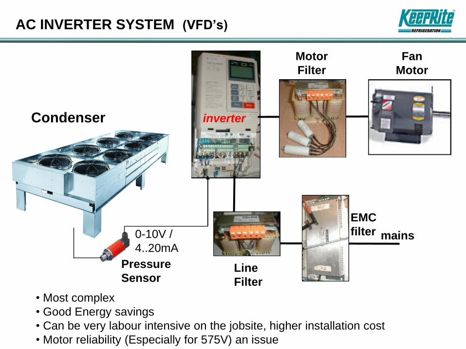
AC INVERTER SYSTEM (VFD’s)
inverter
Motor
Filter
Pressure
Sensor
mains
EMC
filter
Line
Filter
0-10V /
4..20mA
Condenser
• Most complex
• Good Energy savings
• Can be very labour intensive on the jobsite, higher installation cost
• Motor reliability (Especially for 575V) an issue
Fan
Motor

pressure
sensor
EC MOTOR SYSTEM (Factory Controls)
0-10V /
4..20mA
0-10V
Condenser mains
• No Filters
• Easier to understand & setup
• More reliable
• Best energy savings
0-10V
0-10V

0-10V / 4..20mA
0-10V
Condenser mains
0-10V
0-10V
From Rack
Controller
EC MOTOR SYSTEM (Controls by others)

LETS INVESTIGATE FURTHER
MOST COMMON APPLICATIONS
AIR COOLED CONDENSERS
FAN CYCLING vs. EC MOTORS
AIR COOLED CONDENSING UNITS
FLOODED SYSTEM vs. EC MOTORS

4.5 X less energy or
80% Savings
66 dBA
52 dBA
59 dBA
65 dBA
Payback on 8 EC Fan Condenser < 1 Year
SOURCE: KEEPRITE REFRIGERATION ENGINEERING

76 dBA
68 dBA
60 dBA
56 dBA
SOURCE: KEEPRITE REFRIGERATION ENGINEERING
-85% vs. 1140
-70% vs. 850
-50% vs. 550
@ Typical Op
Range
Let’s Quantify

ENERGY SAVINGS (BIN ANALYSIS)
EC Fan Motors with
Fan Speed Control ( All Fans ) AC Motors with
Fan Cycling
VS.
5. Let’s Quantity Further

67% LESS ENERGY = 58,307 kWh
@ $0.10/kWh = $5,831
Payback ≈ 2 years***
***Depending on location
Philadelphia, PA

Let’s Quantity Further
AIR COOLED CONDENSING UNITS
2 HP System - Cooler
Flooded System
for HPC
VS.
Variable Speed
EC Fan Motor
for HPC
ENERGY SAVINGS (BIN ANALYSIS)

ENERGY SAVINGS (BIN ANALYSIS) 2 HP COOLER w/ FLOODED VALVE

-2934
-$235
+32%
SAME BIN ANALYSIS AS BEFORE ENERGY SAVINGS (BIN ANALYSIS) 2 HP COOLER w/ Variable Speed EC

WHAT MAKES EC MOTOR SO SPECIAL
• HIGHEST EFFICIENCY AT REDUCED SPEED
• LOW HEAT GENERATION AT LOW SPEEDS
• ABILITY TO REDUCE TO LOWER SPEEDS
• SOFT STARTS AND NO START UP TORQUES
• ABILITY TO BE CONTROLLED BY LOW VOLTAGE SIGNAL
• HIGHEST RELIABILITY IN LOW AMBIENTS
• GIVES MORE ENERGY SAVINGS AND MORE RELIABILITY
• SIMPLE TO INSTALL AND UNDERSTAND
• CONVENIENCE OF SETTING ADJUSTABLE HEAD PRESSURE…

6. Floating Head Pressure Design / Concepts
• NEEDED TO MEET ENERGY AND GREEN DEMANDS
• NEED TO MEET CURRENT AND FUTURE LEGISLATION (CALIFORNIA TILTE 20 & 24, EISA 2007 etc)
Capacity / Power Input at +40°F Evap T
10
11
11.5
12
12.5
13
13.5
85 105 125
Condensing T °F
Cap
ac
ity T
ON
S
6
7
8
9
10
11
12
13
14
Po
we
r in
pu
t k
W
Q P
Allowing Head Pressure ( Condensing Temperature ) in Refrigeration Systems to operate at reduced
levels ( “Float Down” ) during periods of Low Ambient can result in:
Increased Compressor
Efficiency
Lower Compressor
Motor Amperage
(Power Input )

X ELIMINATE
FLOODING VALVE
FOCUS ON
CONDENSER
FIND WAY
TO OPERATE
AS LOW AS
POSS.
ENSURE 100%
LIQUID @ TXV
ENSURE PROPER
APPLICATION /
BALANCE AT
EVAP
ADEQUATE
SUPERHEAT
AT COMP
REFRIGERANT
SAVINGS
WHAT NEEDS TO BE DONE?
OPTIMIZE
BTUH/W
Floating Head Pressure Design / Concepts

Floating Head Pressure Design Concepts
When Ambient T is below the design Ambient T we can take advantage of the greater condenser capacity.
We can benefit by lowering the head pressure ( “Float Down”) and get more compressor capacity
To a point !
IF Head Pressure is allowed to fall below certain Minimum Values
System Performance can be adversely affected in the following areas:
1. Starving Evaps by Underfeeding TXV’s
2. Oil Return / Oil Logging
3. Compressor Efficiency and Higher Discharge T’s / Super Heat

Floating Head Pressure Design/Concepts
1. Starving Evaps by Underfeeding TXV’s
Lowering Head Pressure
(Cond T) results in a
ΔP reduction which will
DECREASE
TXV Capacity
Lower Condensing T
( Lower Liquid T) will
INCREASE
TXV Capacity
The effect of
LowerΔP - (Reduced Valve Capacity) and
Lower Liquid Temperature ( Increased Valve Capacity)
Will tend to offset each other without any significant change in TXV Capacity
Lower Head Pressure requires less motor current and increases compressor efficiency.
There is a Limit
If Lowered Too Far the TXV Capacity will not be able to meet Evaporator load
Starving the Evap of Liquid Refrigerant Reducing Evap Capacity.

Floating Head Pressure Design/Concepts
2. Oil Return / Oil Logging
• Refrigerant and Oil do not mix completely
• For all the Oil to return properly to the compressor requires a
minimum refrigerant velocity in the suction line (particularly the riser).
• If the Evap is starved ( from lower head pressure, available ΔP) the
refrigerant mass flow in the evaporator will start decreasing.
• If the velocity is too low refrigerant will not return to the suction
riser – It will LOG in the Evaporator.
• Oil logged in the evaporator will coat the inner wall of the coil and
reduce heat transfer through the walls. This will cause a loss of
capacity and poor performance and may rob the compressor of oil
for lubrication.
Floating Head Pressure Design/Concepts
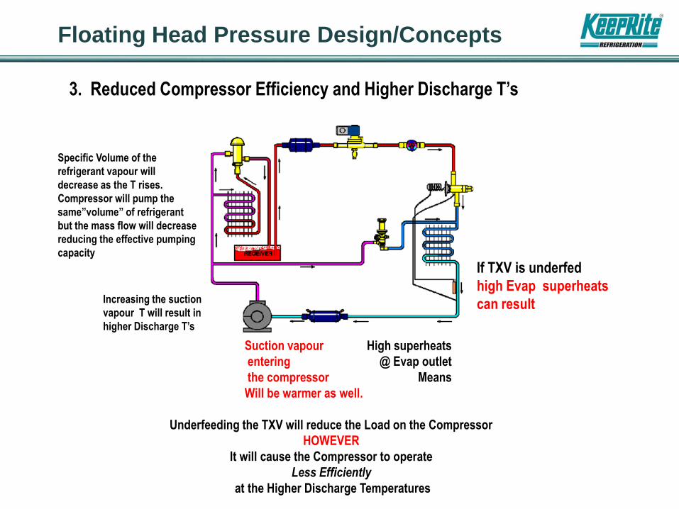
3. Reduced Compressor Efficiency and Higher Discharge T’s
If TXV is underfed
high Evap superheats
can result
High superheats
@ Evap outlet
Means
Increasing the suction
vapour T will result in
higher Discharge T’s
Suction vapour
entering
the compressor
Will be warmer as well.
Underfeeding the TXV will reduce the Load on the Compressor
HOWEVER
It will cause the Compressor to operate
Less Efficiently
at the Higher Discharge Temperatures
Specific Volume of the
refrigerant vapour will
decrease as the T rises.
Compressor will pump the
same”volume” of refrigerant
but the mass flow will decrease
reducing the effective pumping
capacity

• Reducing Head Pressure Lowers the Operating Expense of the Compressor
FLOATING HEAD CONSIDERATIONS
• The determining factor for deciding what the minimum allowable Head Pressure should be is the minimum TXV ΔP required for it’s capacity to meet the demands
of it’s Evaporator Load
• Potential For Lots Of Savings (Up to Approx. 30%)
• System Head Pressure Controls then adjusted to maintain that minimum.
Standard JCI Controls
“A SYSTEM CONFIGURATION THAT CAN OPERATE IN A WIDE RANGE OF AMBIENTS
AND
SAVE ENERGY AND REFRIGERANT”

FLOATING HEAD CONSIDERATIONS / FINDINGS
Potential for Reduced
Amount
Of Refrigerant –
EC Fans + Condenser
Splitting
Be Aware Of Your Ambient T
and Compressor Limitations
Lowest condensing temp is
not necessary optimal
Liquid -Suction Heat Xer
Needed To Ensure
Pure (100%) Liquid at Evap
Balanced Port TXV Will Work
Many Locations & Applications
HOWEVER
EEV Is Recommended for
System Optimization &
Especially For Proper Operation
in Low Ambient T
Low Ambient T’s May Need To Still
Consider Use of Flooding Valve(s)

40
• Standard fixed port valve does not cut it, balance port is better
• Additional hpc needed for lower ambient (EC as variable)
• Lowest condensing temp is not necessary optimal
• Too much capacity leads to high TD’s and low humidity levels
• High TD’s will effect product integrity and amount of
condensate on the coil (icing issues)
• SLHX needed to ensure 100% liquid
• EEV’s increase operating envelope of operation but does not
resolve the issue of too much capacity!
• More system modification needed to allow to operate in lower
ambient...ORI/ORD?

Thank You For Your Attention
NOW
Questions / Discussion / Input