w i version 2016q1 - cncrouterparts · cnc r p mx4660 diy kit w i version 2016q1.1. mx4660 diy...
TRANSCRIPT
CNC R����� P����MX4660 DIY KitW����� I�����������
Version 2016Q1.1

MX4660 DIY Instructions CONTENTS
Contents
1 Introduction 3
2 Power Wiring 4
3 Motor Wiring 6
4 Emergency Stop Connection 8
5 Dip Switch Settings 9
6 PC Connection 10
7 Proximity Switch Wiring 117.1 Terminal Block Setup . . . . . . . . . . . . . . . . . . . . . . . . . . . . . . . . 127.2 Strip Wires for Switches . . . . . . . . . . . . . . . . . . . . . . . . . . . . . . . 147.3 Install Wires in Terminal Blocks . . . . . . . . . . . . . . . . . . . . . . . . . . . 167.4 Install X+ and X- Sensors . . . . . . . . . . . . . . . . . . . . . . . . . . . . . . 177.5 Install Y+ and Y- Sensors . . . . . . . . . . . . . . . . . . . . . . . . . . . . . . 177.6 Install Slaved Homing Sensor . . . . . . . . . . . . . . . . . . . . . . . . . . . 187.7 Connect Terminals to MX4660 . . . . . . . . . . . . . . . . . . . . . . . . . . 197.8 Connect Ground Terminals . . . . . . . . . . . . . . . . . . . . . . . . . . . . 197.9 Connect 12V Power Terminals . . . . . . . . . . . . . . . . . . . . . . . . . . 207.10 Connect Input Signal Terminals . . . . . . . . . . . . . . . . . . . . . . . . . . 21
MX4660 DIY InstructionsVersion 2016Q1.1
Copyright©2015 CNC Router Parts LLC.All Rights Reserved. 1

DisclaimerWorking with electricity can expose you to dangerous or lethal AC currents. While thisguide contains helpful information, you are responsible for keeping yourself safe. If youare at all unsure about completing any aspect of your electrical wiring, hire a licensedelectrician or qualified electrical contractor to assist you. Users of this content agreethat use of this guide and all products or content contained herein are at your ownrisk, and there is no warranty expressly made or implied herein.

MX4660 DIY Instructions
1 IntroductionThe integrated design of the MX4660 greatly simplifies the wiring and setup of a Nema23 system. However, it can still be a bit daunting for those new to electronics andCNC, so in that light we have created this step by step guide to help get you goingwith our products. The first step is to insure you have all of the parts needed – theseare shown below. You will need an AC power cable, a DC power supply, some 18AWG or larger wire to connect the power supply, a motor, a motor cable, a parallelport cable (or optional Ethernet Smooth Stepper and ribbon cable), and the MX4660drive. It’s also recommended to have an emergency stop, but if you don’t have one,you can jumper this out initially while you’re testing motors o� of your machine. Theinstructions below show you how to hook the system up with a jumper installed at theemergency stop input.
Next you will want to make sure you have a few tools handy – a Philips head screwdriverfor the power supply, a small Philips for the MX4660 connections, and a set of wirestrippers will be needed. For a professional install, ferrules and crimps can be used onyour wire ends, but this isn’t strictly necessary.
MX4660 DIY InstructionsVersion 2016Q1.1
Copyright©2015 CNC Router Parts LLC.All Rights Reserved. 3

MX4660 DIY Instructions
2 Power WiringStart by verifying that the DC power supply is set to the correct input voltage for yourapplication (in the US it should be 115V as shown). This can be changed by sliding thered switch to the left or right.
Next you will need to cut the female end o� of an AC power cord. Almost any cordwill su�ce – a standard PC power cord is a good choice. Strip the ends o� of thewires (make sure the cable is not plugged into the wall!), and crimp on ring or spadeterminals if desired.
MX4660 DIY InstructionsVersion 2016Q1.1
Copyright©2015 CNC Router Parts LLC.All Rights Reserved. 4
MX4660 DIY Instructions
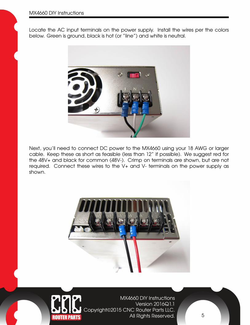
Locate the AC input terminals on the power supply. Install the wires per the colorsbelow. Green is ground, black is hot (or ”line”) and white is neutral.
Next, you’ll need to connect DC power to the MX4660 using your 18 AWG or largercable. Keep these as short as feasible (less than 12” if possible). We suggest red forthe 48V+ and black for common (48V-). Crimp on terminals are shown, but are notrequired. Connect these wires to the V+ and V- terminals on the power supply asshown.
MX4660 DIY InstructionsVersion 2016Q1.1
Copyright©2015 CNC Router Parts LLC.All Rights Reserved. 5
MX4660 DIY Instructions
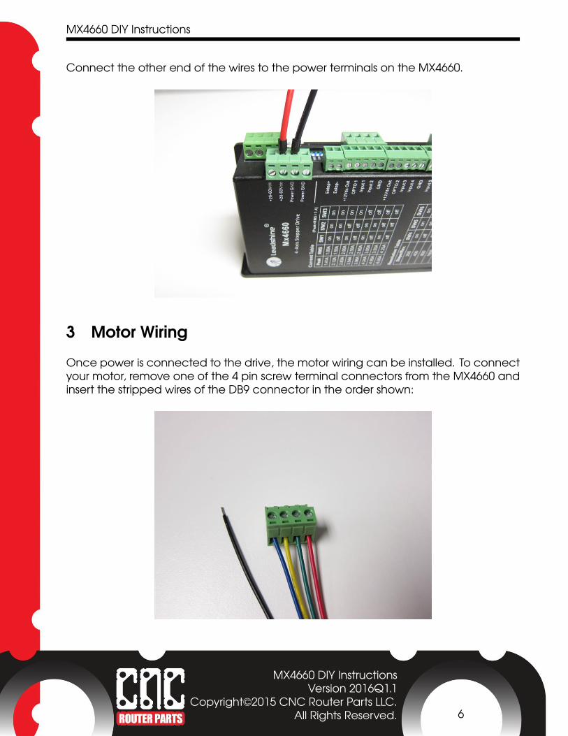
Connect the other end of the wires to the power terminals on the MX4660.
3 Motor WiringOnce power is connected to the drive, the motor wiring can be installed. To connectyour motor, remove one of the 4 pin screw terminal connectors from the MX4660 andinsert the stripped wires of the DB9 connector in the order shown:
MX4660 DIY InstructionsVersion 2016Q1.1
Copyright©2015 CNC Router Parts LLC.All Rights Reserved. 6

MX4660 DIY Instructions
This 4 pin screw terminal connector should then be reinserted into the MX4660:
The DB9 wire from the motor can now be connected to the DB9 panel mount wiredto the MX4660:
MX4660 DIY InstructionsVersion 2016Q1.1
Copyright©2015 CNC Router Parts LLC.All Rights Reserved. 7
MX4660 DIY Instructions
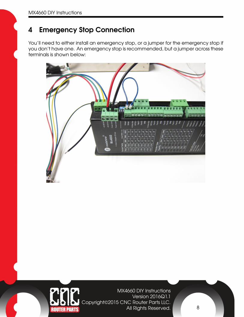
4 Emergency Stop ConnectionYou’ll need to either install an emergency stop, or a jumper for the emergency stop ifyou don’t have one. An emergency stop is recommended, but a jumper across theseterminals is shown below:
MX4660 DIY InstructionsVersion 2016Q1.1
Copyright©2015 CNC Router Parts LLC.All Rights Reserved. 8
MX4660 DIY Instructions
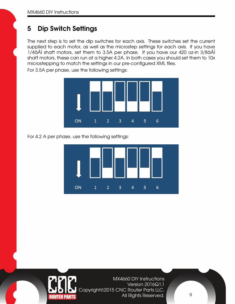
5 Dip Switch SettingsThe next step is to set the dip switches for each axis. These switches set the currentsupplied to each motor, as well as the microstep settings for each axis. If you have1/4� shaft motors, set them to 3.5A per phase. If you have our 420 oz-in 3/8�shaft motors, these can run at a higher 4.2A. In both cases you should set them to 10xmicrostepping to match the settings in our pre-configured XML files.For 3.5A per phase, use the following settings:
For 4.2 A per phase, use the following settings:
MX4660 DIY InstructionsVersion 2016Q1.1
Copyright©2015 CNC Router Parts LLC.All Rights Reserved. 9

MX4660 DIY Instructions
6 PC ConnectionTo connect the drive to your PC, we highly recommend the Ethernet Smoothstepper(ESS). This board eliminates a number of issues with older parallel port interfaces, andalso allows you to run on modern operating systems or laptops. If you are using one ofthese units, use the supplied ribbon cable and gender changer to plug into the DB-25port on the MX4660.
Connect the 26 pin ribbon connector on the Smoothstepper, using PORT 1 on theSmoothstepper.
MX4660 DIY InstructionsVersion 2016Q1.1
Copyright©2015 CNC Router Parts LLC.All Rights Reserved. 10

MX4660 DIY Instructions
If you need help setting up your Ethernet Smooth Stepper with Mach3, please see ourEthernet Smoothstepper GuideIf you’re using a parallel port cable, make sure any DB25 cable you use is fully pop-ulated – many cheap printer cables do not have all of the pins going through, andare often missing conductors that are assigned to step and direction signals on theMX4660. Run this cable from the DB-25 port on the MX4660 directly to your PC parallelport in this configuration.All that is left in order to get moving is to configure Mach 3 for operation of the MX4660.This can be done with the XML File we provide for this system – you will want the CRP100XML file.
7 Proximity Switch WiringWhile it’s not necessary to get your machine moving, the MX4660 o�ers support forlimit and home switches. The MX4660 o�ers on-board 12V power that can be usedfor powered proximity switches, which are documented below. In addition to limitswitches, we recommend using terminal blocks for connecting up power and groundsignals, and for combining X+/X- and Y+/Y- signals into a single input.The instructions below go through the physical wiring of limit switches into the MX4660.For instructions on setting up limit and homing switches on your machine and in soft-ware, see our Proximity Limit Switch Instructions
MX4660 DIY InstructionsVersion 2016Q1.1
Copyright©2015 CNC Router Parts LLC.All Rights Reserved. 11
MX4660 DIY Instructions 7.1 Terminal Block Setup
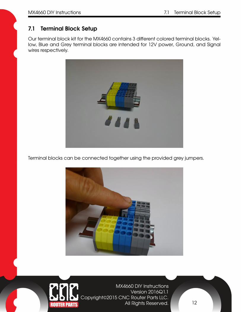
7.1 Terminal Block SetupOur terminal block kit for the MX4660 contains 3 di�erent colored terminal blocks. Yel-low, Blue and Grey terminal blocks are intended for 12V power, Ground, and Signalwires respectively.
Terminal blocks can be connected together using the provided grey jumpers.
MX4660 DIY InstructionsVersion 2016Q1.1
Copyright©2015 CNC Router Parts LLC.All Rights Reserved. 12
MX4660 DIY Instructions 7.1 Terminal Block Setup
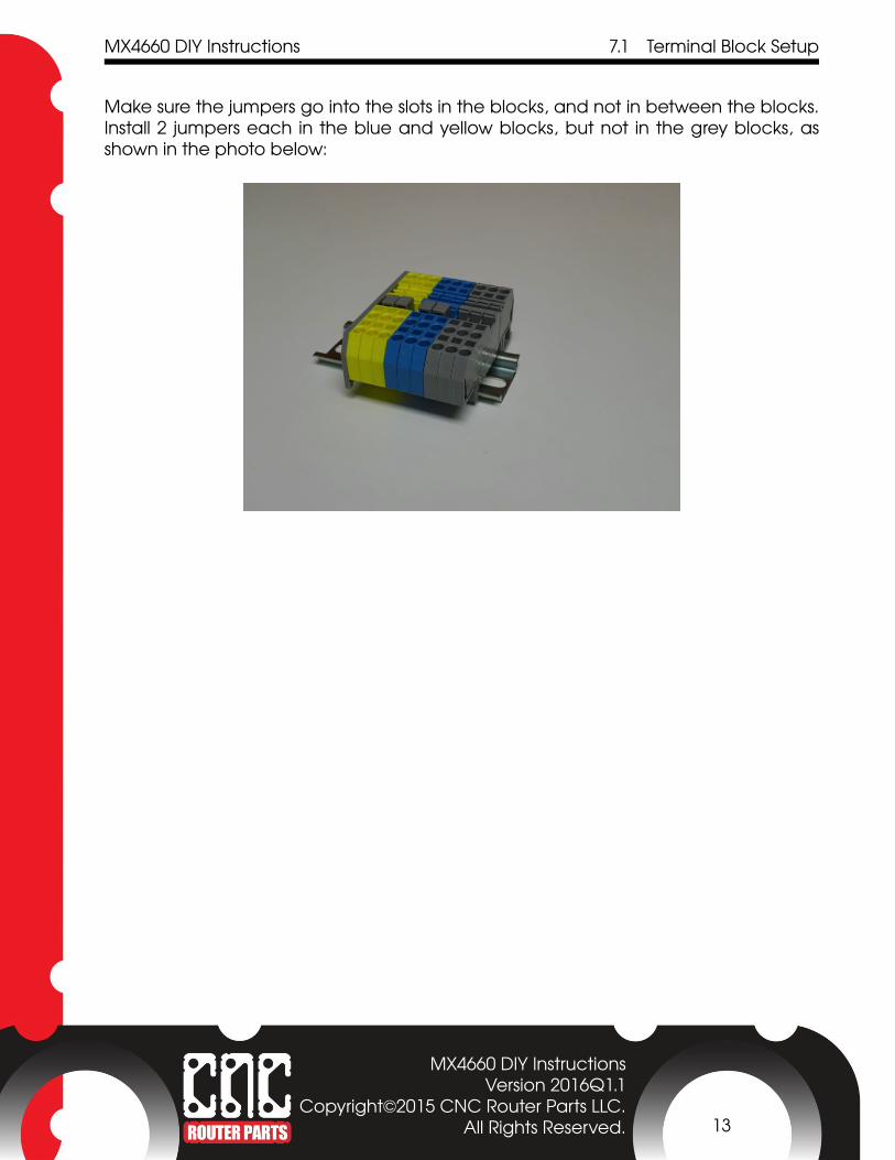
Make sure the jumpers go into the slots in the blocks, and not in between the blocks.Install 2 jumpers each in the blue and yellow blocks, but not in the grey blocks, asshown in the photo below:
MX4660 DIY InstructionsVersion 2016Q1.1
Copyright©2015 CNC Router Parts LLC.All Rights Reserved. 13

MX4660 DIY Instructions 7.2 Strip Wires for Switches
7.2 Strip Wires for SwitchesThe next step is to prepare your switches to install into the terminal blocks. First, you willneed to cut the male end o� of the supplied M12 cables.
MX4660 DIY InstructionsVersion 2016Q1.1
Copyright©2015 CNC Router Parts LLC.All Rights Reserved. 14
MX4660 DIY Instructions 7.2 Strip Wires for Switches
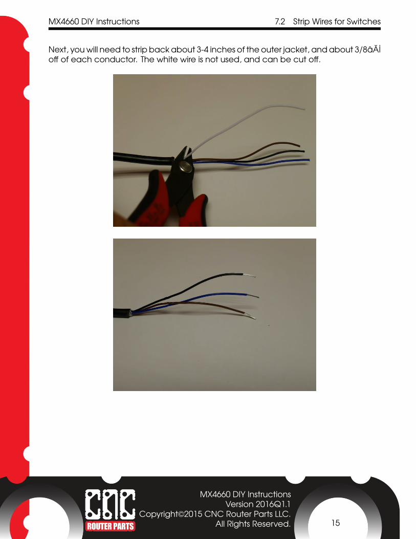
Next, you will need to strip back about 3-4 inches of the outer jacket, and about 3/8�o� of each conductor. The white wire is not used, and can be cut o�.
MX4660 DIY InstructionsVersion 2016Q1.1
Copyright©2015 CNC Router Parts LLC.All Rights Reserved. 15
MX4660 DIY Instructions 7.3 Install Wires in Terminal Blocks
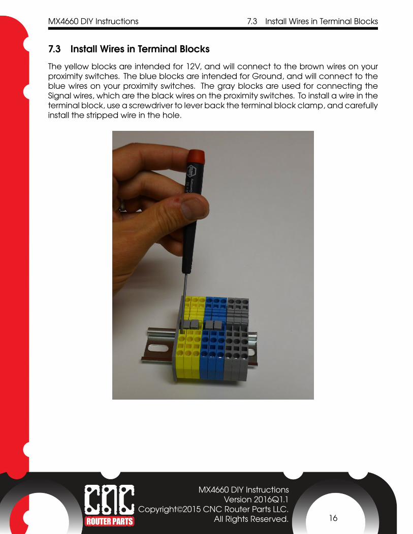
7.3 Install Wires in Terminal BlocksThe yellow blocks are intended for 12V, and will connect to the brown wires on yourproximity switches. The blue blocks are intended for Ground, and will connect to theblue wires on your proximity switches. The gray blocks are used for connecting theSignal wires, which are the black wires on the proximity switches. To install a wire in theterminal block, use a screwdriver to lever back the terminal block clamp, and carefullyinstall the stripped wire in the hole.
MX4660 DIY InstructionsVersion 2016Q1.1
Copyright©2015 CNC Router Parts LLC.All Rights Reserved. 16
MX4660 DIY Instructions 7.4 Install X+ and X- Sensors
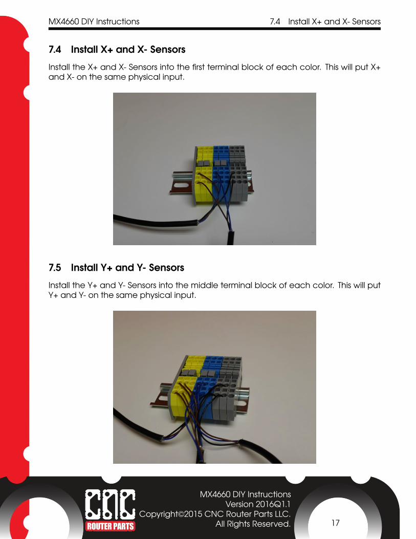
7.4 Install X+ and X- SensorsInstall the X+ and X- Sensors into the first terminal block of each color. This will put X+and X- on the same physical input.
7.5 Install Y+ and Y- SensorsInstall the Y+ and Y- Sensors into the middle terminal block of each color. This will putY+ and Y- on the same physical input.
MX4660 DIY InstructionsVersion 2016Q1.1
Copyright©2015 CNC Router Parts LLC.All Rights Reserved. 17
MX4660 DIY Instructions 7.6 Install Slaved Homing Sensor
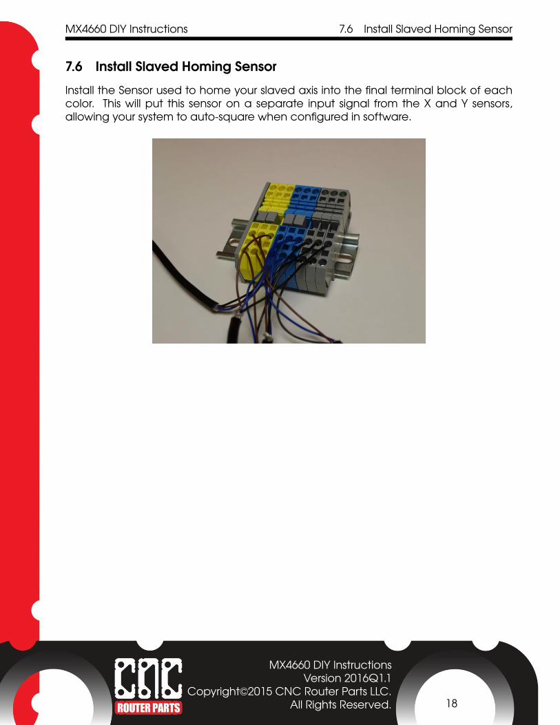
7.6 Install Slaved Homing SensorInstall the Sensor used to home your slaved axis into the final terminal block of eachcolor. This will put this sensor on a separate input signal from the X and Y sensors,allowing your system to auto-square when configured in software.
MX4660 DIY InstructionsVersion 2016Q1.1
Copyright©2015 CNC Router Parts LLC.All Rights Reserved. 18

MX4660 DIY Instructions 7.7 Connect Terminals to MX4660
7.7 Connect Terminals to MX4660The next step in the process is to wire these signals into the terminals on the MX4660.You will be connecting 12V power, Ground, and Signal Wires.
7.8 Connect Ground TerminalsPrepare 2 wires to connect between the blue Ground terminal blocks and the MX4660.
Connect these wires to the screw terminals labeled GND on the MX4660. It does notmatter which wire goes to which terminal block. When you are finished, your setupshould look like the setup below.
MX4660 DIY InstructionsVersion 2016Q1.1
Copyright©2015 CNC Router Parts LLC.All Rights Reserved. 19
MX4660 DIY Instructions 7.9 Connect 12V Power Terminals
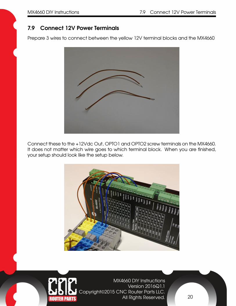
7.9 Connect 12V Power TerminalsPrepare 3 wires to connect between the yellow 12V terminal blocks and the MX4660
Connect these to the +12Vdc Out, OPTO1 and OPTO2 screw terminals on the MX4660.It does not matter which wire goes to which terminal block. When you are finished,your setup should look like the setup below.
MX4660 DIY InstructionsVersion 2016Q1.1
Copyright©2015 CNC Router Parts LLC.All Rights Reserved. 20

MX4660 DIY Instructions 7.10 Connect Input Signal Terminals
7.10 Connect Input Signal TerminalsPrepare 3 wires to connect between the grey Signal terminal blocks and the MX4660.
Connect these to the Input 1, Input 2, and Input 3 screw terminals on the MX4660.The order in which you install these will impact the pin assignments for your proximityswitches in Mach, so we recommend installing these in order left to right (input 1 to theleft terminal block, input 3 on the right terminal block). When you are finished, yoursetup should look like the setup below.
MX4660 DIY InstructionsVersion 2016Q1.1
Copyright©2015 CNC Router Parts LLC.All Rights Reserved. 21

MX4660 DIY Instructions 7.10 Connect Input Signal Terminals
You have completed the wiring setup. Go to our Proximity Limit Switch Instructions tocomplete installation on your machine and set up your switches in software.
MX4660 DIY InstructionsVersion 2016Q1.1
Copyright©2015 CNC Router Parts LLC.All Rights Reserved. 22