mk6 diy contents: description qty.description - cim · pdf file · 2010-07-10mk6...
TRANSCRIPT

MK6 DIY Contents:
Warning! This DIY is reserved for those who are confident in taking the risk of installing their own boost gauge. If you are unsure for any reason whatsoever, please let a professional install this setup. Concepts In Motion is not and will not be held responsible for any damages or mishaps that may occur during installation. Please proceed at your own risk! Installation instructions: 1. Remove Contents from Box
Description Qty. Description Qty. 45mm Gauge 1 Attachment screws 1 Boost Sensor 1 Vent Pod 1 Power wiring harness 1 Misc. electrical
hardware kit 1
Vacuum line 1 Zip ties 6 In-line filter 1 Boost Tap (Optional) 1 Resistor (red/white gauge only)
1
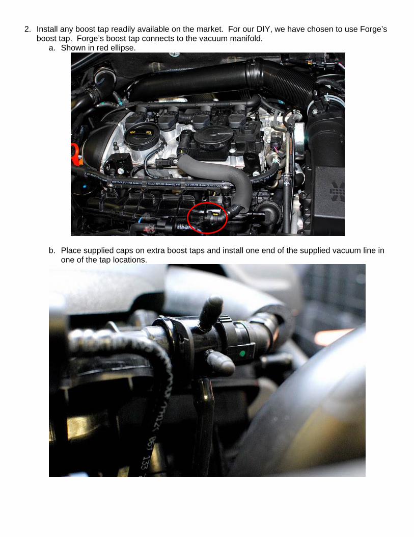
2. Install any boost tap readily available on the market. For our DIY, we have chosen to use Forge’s boost tap. Forge’s boost tap connects to the vacuum manifold.
a. Shown in red ellipse.
b. Place supplied caps on extra boost taps and install one end of the supplied vacuum line in one of the tap locations.
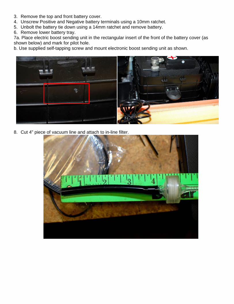
3. Remove the top and front battery cover. 4. Unscrew Positive and Negative battery terminals using a 10mm ratchet. 5. Unbolt the battery tie down using a 14mm ratchet and remove battery. 6. Remove lower battery tray. 7a. Place electric boost sending unit in the rectangular insert of the front of the battery cover (as shown below) and mark for pilot hole. b. Use supplied self-tapping screw and mount electronic boost sending unit as shown.
8. Cut 4” piece of vacuum line and attach to in-line filter.
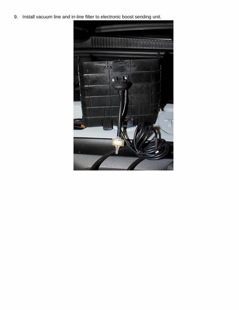
9. Install vacuum line and in-line filter to electronic boost sending unit.

10. Next step is to route the sending unit wires through the firewall. To the left of the battery, along the firewall, is a little rubber boot. Use a coat hanger, or something sharp, to puncture a hole through the rubber boot and feed the hanger through. Make sure to leave slack so you can pull the coat hanger back.
Battery tray

11. Tape the sending unit wire and plug to the coat hanger. Feed/pull coat hanger back through the firewall. *NOTE: BE SURE TO SECURE THE PLUG ON THE HARNESS PROPERLY SO THE WIRES DO NOT GET PULLED OUT OF THE PLUG DURING THIS STEP!
Engine Bay View Interior View
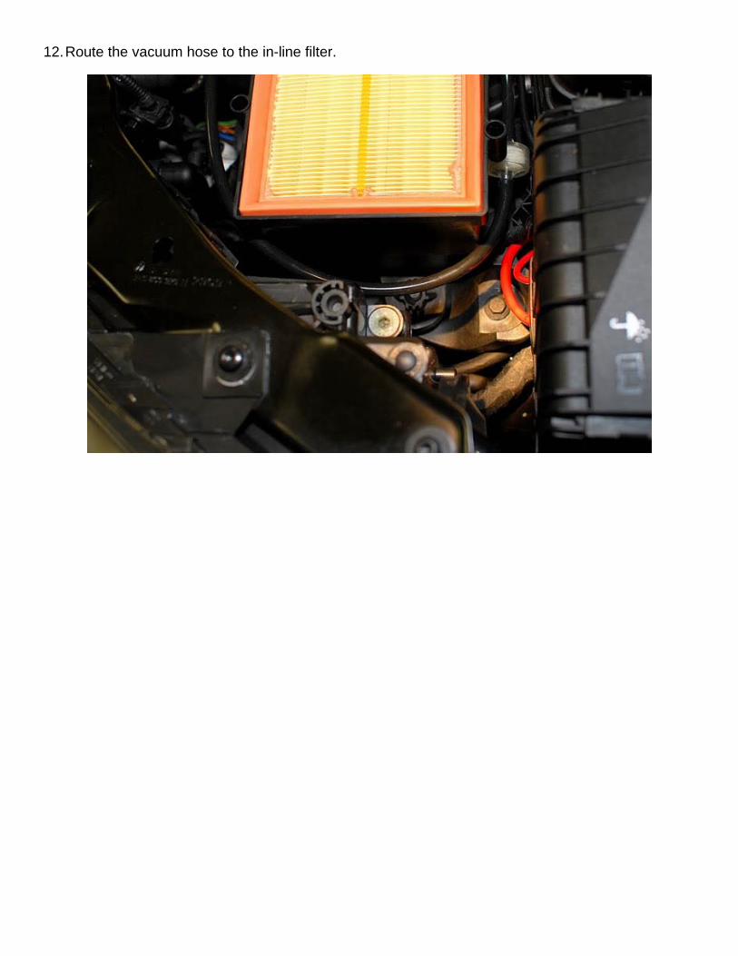
12. Route the vacuum hose to the in-line filter.
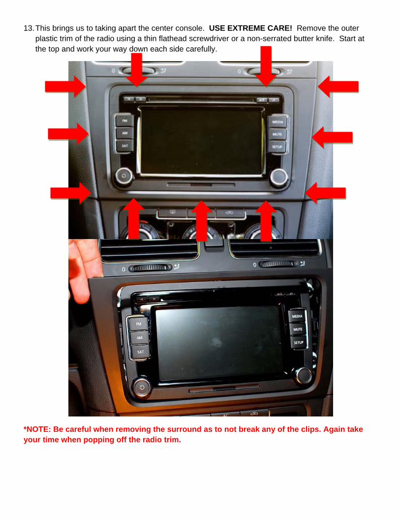
13. This brings us to taking apart the center console. USE EXTREME CARE! Remove the outer plastic trim of the radio using a thin flathead screwdriver or a non-serrated butter knife. Start at the top and work your way down each side carefully.
*NOTE: Be careful when removing the surround as to not break any of the clips. Again take your time when popping off the radio trim.
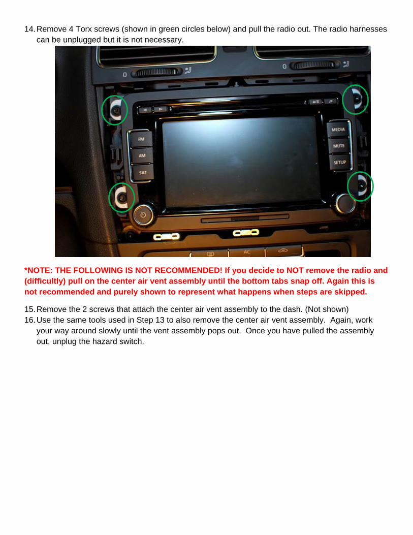
14. Remove 4 Torx screws (shown in green circles below) and pull the radio out. The radio harnesses can be unplugged but it is not necessary.
*NOTE: THE FOLLOWING IS NOT RECOMMENDED! If you decide to NOT remove the radio and (difficultly) pull on the center air vent assembly until the bottom tabs snap off. Again this is not recommended and purely shown to represent what happens when steps are skipped.
15. Remove the 2 screws that attach the center air vent assembly to the dash. (Not shown) 16. Use the same tools used in Step 13 to also remove the center air vent assembly. Again, work
your way around slowly until the vent assembly pops out. Once you have pulled the assembly out, unplug the hazard switch.

17. Once the vent assembly is removed and the hazard switch wiring is detached remove the entire hazard switch by using a flat head screw driver and pushing in on the metal clips on each side while pushing the switch from the front.
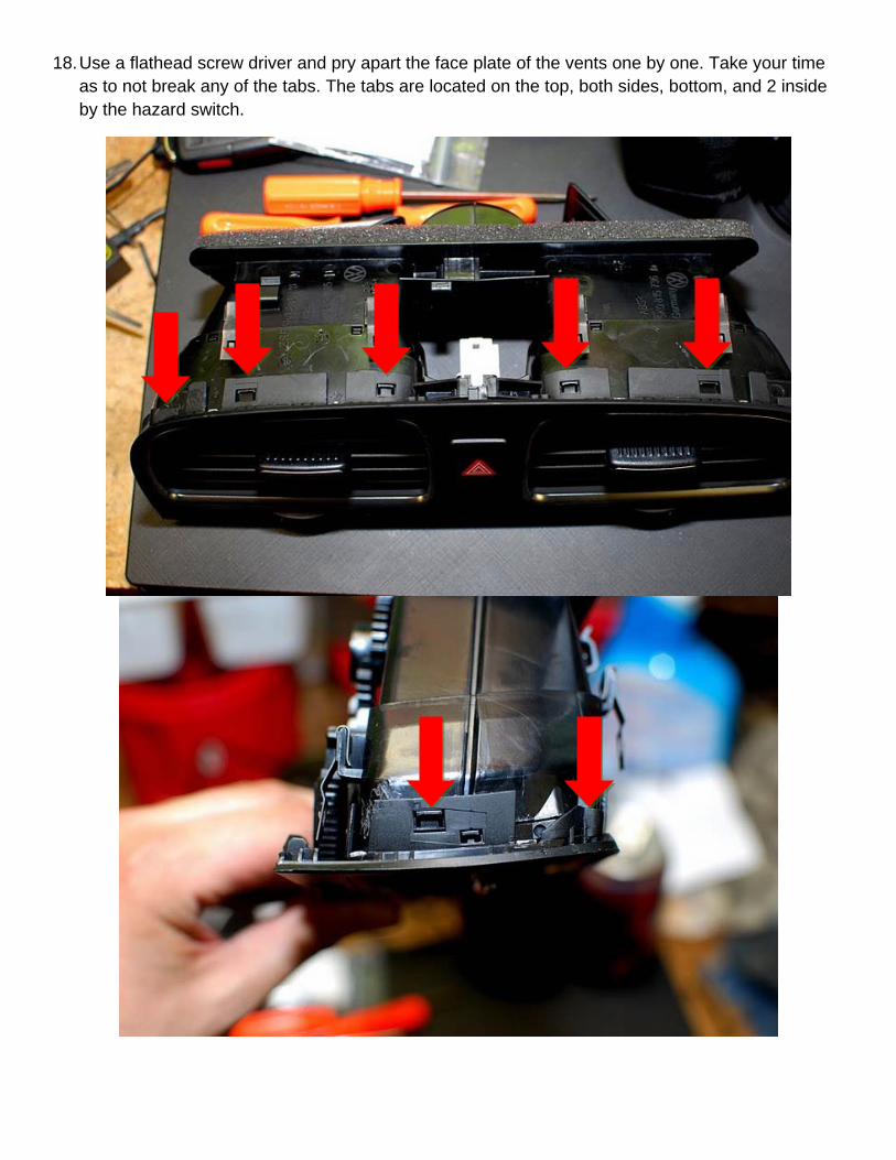
18. Use a flathead screw driver and pry apart the face plate of the vents one by one. Take your time as to not break any of the tabs. The tabs are located on the top, both sides, bottom, and 2 inside by the hazard switch.
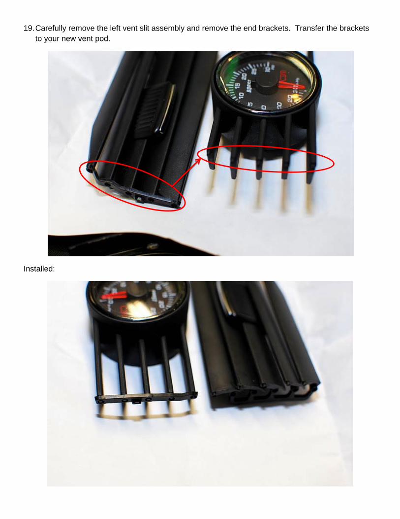
19. Carefully remove the left vent slit assembly and remove the end brackets. Transfer the brackets to your new vent pod.
Installed:

Both sides installed : NOTE: Clear protective film is still on the gauge and not recommended to be removed until install is complete
20. Remove vertical air vents by using a flat head screw driver to pop out the bottom.

21. Drill a 3/8” hole on side of vent as shown below:
22. Using the same coat hanger as before, route the hanger, with the boost sensor harness still attached, from underneath the driver’s dash to the center console. Detach the hanger from the plug. Now attach the power harness in the same manner and route it from the center console down underneath the driver’s dash.
23. Once the wires are pulled through, leave some slack to make the vent gauge reassembly easier.
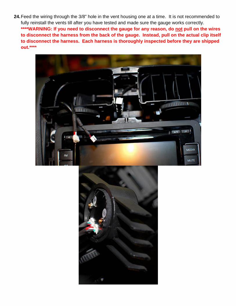
24. Feed the wiring through the 3/8” hole in the vent housing one at a time. It is not recommended to fully reinstall the vents till after you have tested and made sure the gauge works correctly. ****WARNING: If you need to disconnect the gauge for any reason, do not pull on the wires to disconnect the harness from the back of the gauge. Instead, pull on the actual clip itself to disconnect the harness. Each harness is thoroughly inspected before they are shipped out.****
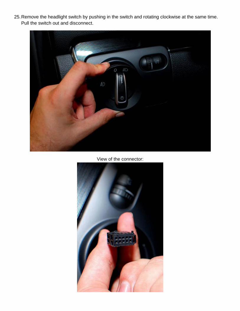
25. Remove the headlight switch by pushing in the switch and rotating clockwise at the same time. Pull the switch out and disconnect.
View of the connector:
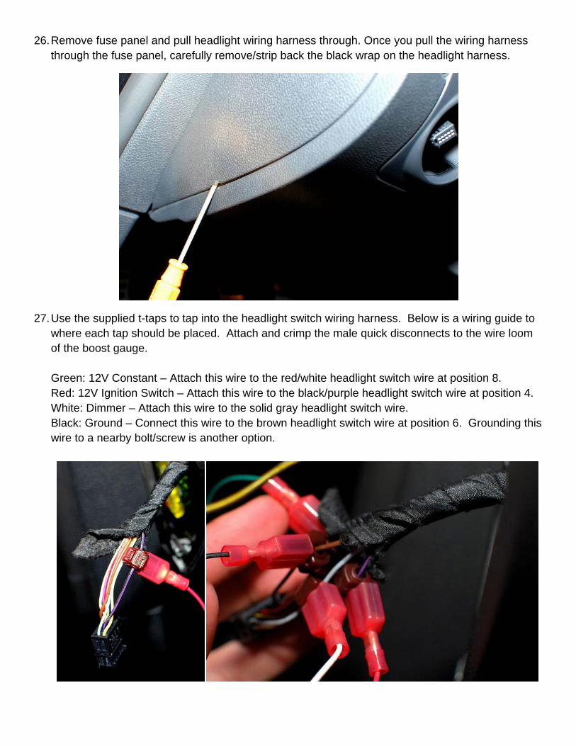
26. Remove fuse panel and pull headlight wiring harness through. Once you pull the wiring harness through the fuse panel, carefully remove/strip back the black wrap on the headlight harness.
27. Use the supplied t-taps to tap into the headlight switch wiring harness. Below is a wiring guide to where each tap should be placed. Attach and crimp the male quick disconnects to the wire loom of the boost gauge. Green: 12V Constant – Attach this wire to the red/white headlight switch wire at position 8. Red: 12V Ignition Switch – Attach this wire to the black/purple headlight switch wire at position 4. White: Dimmer – Attach this wire to the solid gray headlight switch wire. Black: Ground – Connect this wire to the brown headlight switch wire at position 6. Grounding this wire to a nearby bolt/screw is another option.

28. Feed the wiring loom down under the dash using a coat hanger just as before. Run the new wiring from the headlight under the dash to the wiring of the gauge. Make sure the wiring does not interfere with the pedals zip tying along the way. Trim excess wiring (make sure not to cut the supplied resistor off the white wire) and attach male quick disconnects to the gauge side and female quick disconnects to the wire loom side coming from the headlight T-Splice.
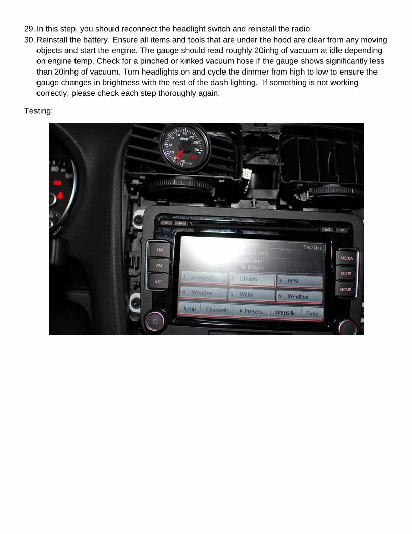
29. In this step, you should reconnect the headlight switch and reinstall the radio. 30. Reinstall the battery. Ensure all items and tools that are under the hood are clear from any moving
objects and start the engine. The gauge should read roughly 20inhg of vacuum at idle depending on engine temp. Check for a pinched or kinked vacuum hose if the gauge shows significantly less than 20inhg of vacuum. Turn headlights on and cycle the dimmer from high to low to ensure the gauge changes in brightness with the rest of the dash lighting. If something is not working correctly, please check each step thoroughly again.
Testing:

Dash fully reinstalled: