vuelock™ anterior cervical plate system
TRANSCRIPT

© 2009 EBI, LLC. All rights reserved. P/N 207001L rev. 2/09
All trademarks are the property of Biomet, Inc. or one of its subsidiaries, unless otherwise indicated.Rx Only.
100 Interpace ParkwayParsippany, NJ 07054www.biometspine.com800-526-2579

VueLock® Anterior Cervical Plate System
Surgical Technique
Contents
Introduction................................................................ Page 1
Design Features.......................................................... Page 2
System Components .................................................. Page 3
Surgical Technique .................................................... Page 6
Additional Surgical Options........................................ Page 17
Closure & Postoperative Care .................................... Page 18
Indications For Use .................................................... Page 19
Contraindications ...................................................... Page 19
Warnings.................................................................... Page 20
Sterilization Reccomendations .................................. Page 20
Ordering Information.................................................. Page 21
Further Information .................................................... Page 23

The VueLock® Anterior Cervical Plate System offers spine
surgeons simplicity, efficiency, and versatility. Overall, the
VueLock Anterior Cervical Plate System’s low profile and
various component options provide a competitive edge
within the cervical spine market.
Introduction
1

VueLock Cervical System
Design Features
2
One-step locking mechanism
The system includes Self-Tapping and Self-Drilling Bone
Screws, which are positioned and locked in a one-step
procedure that facilitates surgeon ease of use. This unique
locking mechanism eliminates the need for additional locking
components. Additionally, the bone screws may be
positioned at a fixed or variable angle.
The unique open design provides excellent intra-operative
visualization of the bone graft and endplates, allowing for
greater postoperative visualization on the AP x-ray.
Self-Tapping Bone Screw designprovides exceptional purchase.
Excellent intra-operative andpost-operative visualization ofthe intervertebral space.
Self-Drilling Bone Screw designoffers optimized cutting flutes thatprovide quicker bone screw purchase.No pre-drilling required.

System Components - Implants
3
The VueLock Anterior Cervical Plate System is an anterior
cervical spinal fixation device made from titanium alloy
(Ti-6Al-4V). Precontoured plates that conform to the natural
lordotic curvature of the spine are available in one, two, three
and four level configurations ranging from 12mm - 92mm in
length. The system also includes Self-Tapping and Self-Drilling
Bone Screws available in two diameters and several lengths.
Bone Screws
Plates
12mm 14mm 16mm
Self-DrillingSelf-Tapping
• One, two, three and four level configurations
• Sizes ranging from 12mm - 92mm in length
VueLock Cervical System
• Color Coded Bone Screw Lengths
- 12mm - green
- 14mm - silver
- 16mm - blue
• 4.0mm and 5.0mm diameters
• Self-Tapping / Self-Drilling
4.0mm 5.0mm
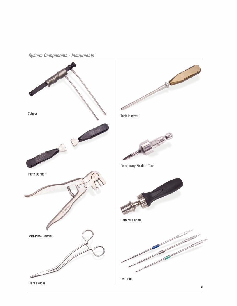
System Components - Instruments
4
Temporary Fixation Tack
CaliperTack Inserter
General Handle
Drill BitsPlate Holder
Mid-Plate Bender
Plate Bender

Fixed Drill Guide
Standard Awl
Variable Drill Guide
Self Centering Awl
Screw Inserter
Screw Retaining Sleeve
Final Tightener
Screw Remover
5

Surgical Technique
6
Surgical Approach and Preparation
The patient is positioned supine on the operative table with a
folded towel beneath the intrascapular region to maintain the
head in slight extension. The use of a head halter attached to
an outrigger for traction may be helpful. If fluoroscopy is
used, it can be utilized at this point to confirm positioning
and check that the desired vertebral levels can be
adequately visualized. (See Figure 1)
The standard anterior approach to the mid and lower cervical
spine is utilized. This can be through one of several incisions
with the exposure typically medial to the carotid sheath and
lateral to the trachea and esophagus. Adequate fascial plane
release is important for optimal exposure. After identification
of the disc space through intraoperative confirmation of
levels with x-ray, preparation for anterior interbody fusion
is begun. (See Figure 2)
The discectomy and resection of osteophytes is performed.
Further preparation of the interbody fusion bed or for
corpectomy is performed as indicated. (See Figure 3)
Interbody grafts or a strut graft is then positioned and
impacted into place. Any distraction previously applied
can be released at this point to assess graft stability. It is
critical to remove anterior osteophytes for proper plate
placement. Repeat the procedure at each disc space as
necessary. (See Figure 4)
Figure 1
Figure 2
Figure 3
Figure 4

The Plate Holder may be utilized to insert and hold the plate
during the selection process.
The Plate Holder will lock onto any portion of the central
post(s). To attach the Plate Holder to the plate, engage the
distal tips around the central post and depress the handles
together to lock in place.
The VueLock plates are available in one, two, three and four
level styles and range in length from 12mm to 92mm.
Select the desired style and estimated plate length.
The appropriate plate length is determined by utilizing the
Caliper. Position the legs of the Caliper until the desired
screw position is achieved at the superior and inferior ends.
This allows for cephalad and caudal screw angulation and
helps ensure that the plate does not extend over the adjacent
unfused disc spaces.
Insert and position the plate on the anterior surface of the
spine with the Plate Holder. Review landmarks to ensure
that the plate is centered appropriately medially/laterally on
the spine. Confirm that the superior and inferior screw holes
are in correct position on the vertebral bodies.
7
Plate Selection and Positioning
Surgical Technique (Continued)
8
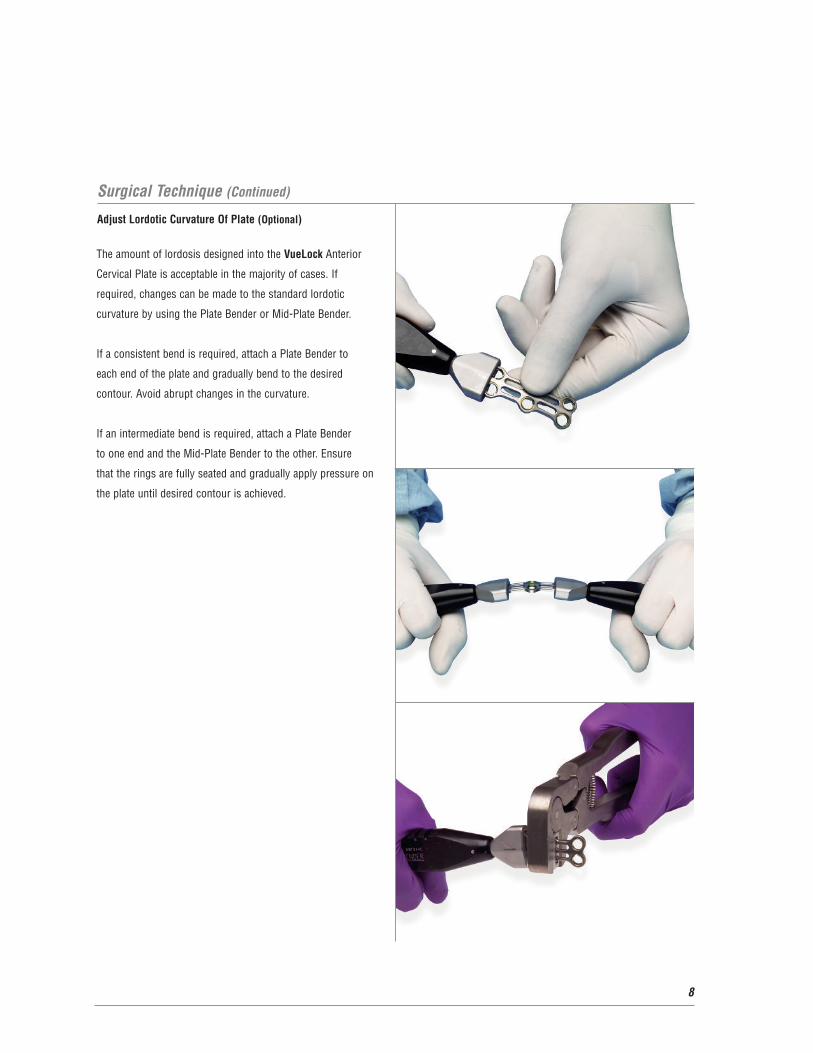
Adjust Lordotic Curvature Of Plate (Optional)
The amount of lordosis designed into the VueLock Anterior
Cervical Plate is acceptable in the majority of cases. If
required, changes can be made to the standard lordotic
curvature by using the Plate Bender or Mid-Plate Bender.
If a consistent bend is required, attach a Plate Bender to
each end of the plate and gradually bend to the desired
contour. Avoid abrupt changes in the curvature.
If an intermediate bend is required, attach a Plate Bender
to one end and the Mid-Plate Bender to the other. Ensure
that the rings are fully seated and gradually apply pressure on
the plate until desired contour is achieved.

After the plate has been positioned, a Temporary Fixation
Tack may be inserted into any of the screw holes to provide
fixation while drilling holes and inserting bone screws.
The Temporary Fixation Tack is positioned utilizing the
Temporary Fixation Tack Inserter. The fixation tacks are
loaded into the tack inserter by pulling back on the locking
sleeve and sliding the tack into place.
The Temporary Fixation Tack is inserted by turning the
tack inserter in a clockwise direction. Once the tack
shoulder is fully seated into the screw hole, the tack inserter
is removed by pulling back on the locking sleeve and
releasing. Additional fixation tacks may be inserted, if desired.
9
Temporary Fixation Tack Insertion (Optional)

Surgical Technique (Continued)
10
Drill Guide Positioning
Drill Guide options are as follows:
• The Fixed Drill Guide presets the convergent angle at 10°
toward the midline of the plate. The cranial/caudal angle
is neutral.
• The Variable Angle Drill Guide allows for a 20° cone of
angulation.
For each guide, the drill guide tip should be fully seated
into the screw hole of the plate. Once the drill guide is
inserted into the bone screw hole, the Variable Angle Drill
Guide is securely locked into the plate by applying light
downward pressure on the drill guide handle. The drill
guide is considered to be fully locked when the distal tip is
flush with the plate. The drill guide tip will engage within
the snap ring in the screw hole.
If the Fixed Drill Guide is used, the guide is locked by
compressing the Rongeur handle and rotating the wheel
180° clockwise.

As an alternative to drilling, an awl may be used to pierce
the anterior cortex to the minor diameter of a 4.0mm bone
screw within the vertebral body. Awl options are as follows:
• The Standard Awl penetrates to a 9mm depth with a Fixed
or Variable Drill Angle Guide.
• The Self Centering Awl pierces the cortex within the
desired depth range of 8-16mm.
Note: To adjust the depth of the Self Centering Awl, depress
the button on the handle and turn the sleeve clockwise to
desired depth marking.
11
Awl Positioning (Optional)

Surgical Technique (Continued)
12
Drill Holes For Bone Screws
The appropriate size Drill Bit is selected based on the
corresponding bone screw size. Bone screw length is measured
by the overall length. After the bone screw is inserted through
the plate, the bone screw purchase is 1mm less (i.e. 14mm
length bone screw results in 13mm of bone purchase).
Screws are available in the following dimensions:
Drill Bits (Color Coded)
• 12mm (Green)
• 14mm (Silver)
• 16mm (Blue)
• 4.0/5.0mm diameters
Bone Screw Diameters:
• 4.0mm (Primary)
• 5.0mm (Salvage/Rescue)
Bone Screw Lengths:
• 12 mm (Green)
• 14mm (Silver)
• 16mm (Blue)
Bone Screw Styles:
• Self-Drilling
• Self-Tapping
12mm 14mm
Self-DrillingSelf-Tapping
4.0mm 5.0mm
16mm

The depth of drilling is controlled by the preset drill stop at
the length of the bone screw. The Drill Bit is designed to
pierce the anterior cortex of the vertebral body and create
the appropriate size and trajectory for the bone screw. Select
the appropriate Drill Bit. The Drill Bits are color-coded and
correspond with the bone screw length colors.
The Drill Bit may be inserted with power or by hand utilizing
the General Handle. If utilizing by hand, attach the desired Drill
Bit to the General Handle by pulling the locking sleeve back
and inserting the Drill Bit into the opening.
Insert the Drill Bit into the drill guide barrel and advance
the drill into the anterior vertebral body to the maximal depth
allowed by the drill stop. For standard applications, bicortical
screw purchase is not necessary. The Self-Tapping Bone
Screw design does not require a separate tap.
Note: Remove the Variable Drill Guide by tilting the guide
medially to release. If utilizing the Fixed Drill Guide, rotate the
wheel until the straight edge releases the guide.
13
Surgical Technique (Continued)
14
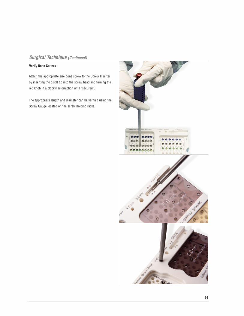
Verify Bone Screws
Attach the appropriate size bone screw to the Screw Inserter
by inserting the distal tip into the screw head and turning the
red knob in a clockwise direction until “secured”.
The appropriate length and diameter can be verified using the
Screw Gauge located on the screw holding racks.
15
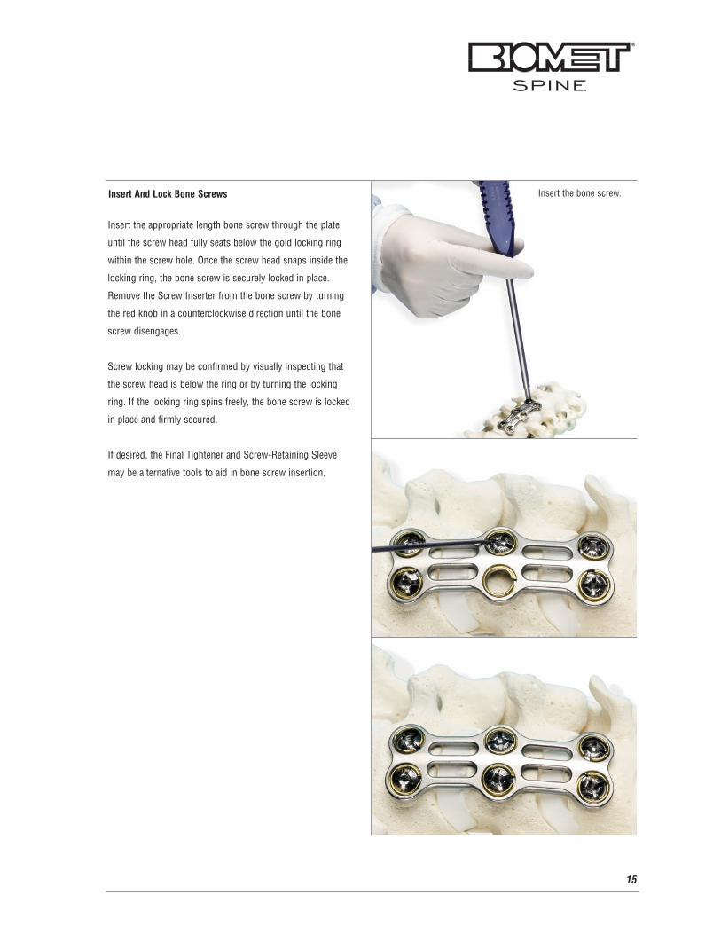
Insert the bone screw.Insert And Lock Bone Screws
Insert the appropriate length bone screw through the plate
until the screw head fully seats below the gold locking ring
within the screw hole. Once the screw head snaps inside the
locking ring, the bone screw is securely locked in place.
Remove the Screw Inserter from the bone screw by turning
the red knob in a counterclockwise direction until the bone
screw disengages.
Screw locking may be confirmed by visually inspecting that
the screw head is below the ring or by turning the locking
ring. If the locking ring spins freely, the bone screw is locked
in place and firmly secured.
If desired, the Final Tightener and Screw-Retaining Sleeve
may be alternative tools to aid in bone screw insertion.

Surgical Technique (Continued)
16
Screw Removal
If a bone screw needs to be repositioned, the Screw
Remover is utilized. Position the distal tip of the
Screw Remover until the cross seats into the bone screw.
Turn the small red knob clockwise until the threads on the inner
shaft engage with the threads in the bone screw. Turn the
silver handle until the cylindrical shaft expands the locking ring.
Turn the red handle counterclockwise until the bone screw
releases. To ease bone screw removal, a Plate Holder may
be used to apply light downward pressure onto the plate.
The screw may now be repositioned utilizing the Screw Inserter.

17
Additional Surgical Options
For cleaning purposes, the Screw Inserter components
may be disassembled by hand. Unthread the inner shaft
counterclockwise until the inner shaft has exited the large
blue outer housing.
For cleaning purposes, the Screw Remover components may
be disassembled by hand. Unthread the inner shaft
counterclockwise until the inner shaft has exited the red
housing. In addition, unthread the silver outer handle clockwise
until the shaft has been completely removed. The components
may be sterilized according to sterilization recommendations.

18
Closure and Post-Operative Care
Closure
After implantation of the VueLock Anterior Cervical Plate
System is complete, closure is performed in layers according
to standard protocol.
Post-Operative Care
A soft collar may be used postoperatively for patient comfort.
Postoperative radiographs should be taken.
Implant Removal
Removal of the VueLock Anterior Cervical Plate System is
performed by reversing the order of the implant procedure.
The Screw Remover is used first to remove the screws from
the locking rings.

19
Indications For Use
The VueLock Anterior Cervical Plate System is intended for
anterior interbody screw fixation of the cervical spine. The
system is indicated for use in the temporary stabilization of
the anterior spine during the development of cervical spinal
fusions in patients with degenerative disc disease (as defined
by neck pain of discogenic origin confirmed by patient history
and radiographic studies), trauma (including fractures),
tumors, deformity (defined as kyphosis, lordosis, or scoliosis),
pseudarthroses, and/or failed previous fusions.
Contraindications
The VueLock Anterior Cervical Plate System is
contraindicated in patients with spinal infection or
inflammation; morbid obesity; mental illness, alcoholism
or drug abuse; pregnancy; metal sensitivity/foreign body
sensitivity; inadequate tissue coverage over the operative
site; or open wounds local to the operative area.

20
Warnings
This device is not approved for screw attachment to the
posterior elements (pedicles) of the cervical, thoracic, or
lumbar spine. Benefit of spinal fusions utilizing any screw
fixation system has not been adequately established in
patients with stable spines. Potential risks identified with
the use of this device system, which may require additional
surgery, include device component fracture, loss of fixation,
non-union, fracture of the vertebra, neurological injury,
and vascular or visceral injury. See the Warnings,
Precautions, and Possible Adverse Effects sections of the
package insert for a complete list of potential risks.
Sterilization Recommendations
The VueLock Anterior Cervical Plate System is provided
nonsterile and must be sterilized prior to use. All packaging
materials must be removed prior to sterilization. The following
steam sterilization parameters are recommended.
Cycle: High Vacuum
Temperature: 270º F/ 132° C
Time: 4 minutes
Note: Allow For Cooling
See Package Insert

21
83112 12mm Plate 2
83114 14mm Plate 2
83116 16mm Plate 2
83118 18mm Plate 2
83120 20mm Plate 2
83122 22mm Plate 2
83124 24mm Plate 2
Ordering Information
VueLock Cervical System Implants
1-Level Plates
Catalog# Description Qty
2-Level Plates
Catalog# Description Qty.
83226 26mm Plate 2
83228 28mm Plate 2
83230 30mm Plate 2
83232 32mm Plate 2
83234 34mm Plate 2
83236 36mm Plate 2
83238 38mm Plate 2
83240 40mm Plate 2
83242 42mm Plate 2
3-Level Plates
Catalog# Description Qty.
83344 44mm Plate 2
83346 46mm Plate 2
83348 48mm Plate 2
83350 50mm Plate 2
83352 52mm Plate 2
83354 54mm Plate 2
83356 56mm Plate 2
83358 58mm Plate 2
83360 60mm Plate 2
83362 62mm Plate 2
83364 64mm Plate 2
83366 66mm Plate 2
4-Level Plates
Catalog# Description Qty.
83460 60mm Plate 2
83464 64mm Plate 2
83468 68mm Plate 2
83472 72mm Plate 2
83476 76mm Plate 2
83480 80mm Plate 2
83484 84mm Plate 2
83488 88mm Plate 2
83492 92mm Plate 2
VueLock Cervical System Bone Screws
Self-Tapping Bone Screws
Catalog# Description Qty.
63025 4.0mm x 12mm 8
63027 4.0mm x 14mm 16
63029 4.0mm x 16mm 8
63050 5.0mm x 12mm 6
63052 5.0mm x 14mm 6
63054 5.0mm x 16mm 6
Self-Drilling Bone Screws
Catalog# Description Qty.
63024 4.0mm x 12mm 1
63028 4.0mm x 14mm 1
63030 4.0mm x 16mm 1
63051 5.0mm x 12mm 2
63053 5.0mm x 14mm 2
63055 5.0mm x 16mm 2

22
Ordering Information (Continued)
VueLock Cervical System Instruments
Instruments
Catalog# Description Qty.
63068 4.0mm Screw Drill Bit with Stop, 12mm 1
63069 4.0mm Screw Drill Bit with Stop, 14mm 1
63070 4.0mm Screw Drill Bit with Stop, 16mm 1
63071 5.0mm Screw Drill Bit with Stop, 12mm 1
63072 5.0mm Screw Drill Bit with Stop, 14mm 1
63073 5.0mm Screw Drill Bit with Stop, 16mm 1
63075 Final Tightener 1
63074 Standard Awl 1
63077 Plate Holder 1
63079 General Handle 1
63080 Temporary Fixation Tack 1
63081 Self Centering Awl 1
63085 Fixed Drill Guide 1
63092 Screw Retaining Sleeve 1
63093 Caliper 1
63094 Screw Remover 1
63095 Screw Inserter 4
63096 Temporary Fixation Tack Inserter 4
63098 Variable Drill Guide 1
63099 Plate Bender 1
63599 Mid-Plate Bender 1

23
Further Information
CAUTION: Federal Law (USA) restricts this device to sale by
or on the order of a physician. This brochure describes the
surgical technique used by Dr. Paul Glazer, M.D. Biomet Spine,
as the manufacturer of this device, does not practice medicine
and does not recommend this product or any specific surgical
technique for use on any individual patient. The surgeon who
performs any implant procedure is responsible for determining
the appropriate product(s) and utilizing the appropriate
technique(s) for said implantation in each individual patient.
For further information, please contact the Customer Service
Department at:
Biomet Spine
100 Interpace Parkway
Parsippany, NJ 07054
(973) 299-9300, (800) 526-2579

24
Notes: