vsd series quick start guide - files.hvacnavigator.com
TRANSCRIPT
Powered by
Eaton’s Technology
VSD Series Quick Start Guide
LIT-1201858
For more information visit:
www.johnsoncontrols.com
1
November 2009
VSD Series Quick Start Guide
Table of Contents
Description Page
NEMA Type 1/12 Open Drives (1 – 250 HP) . . . . . . . . . . . . . .
2
NEMA Type 1 IntelliPass/IntelliDisconnect Drive . . . . . . . . .
5
Enclosed NEMA Type 12/3R . . . . . . . . . . . . . . . . . . . . . . . . . .
10
Appendix A — Main Control Board Wiring . . . . . . . . . . . . .
15
Appendix B — Interlock Damper Start Example Using 4 – 20 mA Control Signal . . . . . . . . . . . . . . . . . . .
16
Appendix C — Interlock Damper Start Example Using PID Duct Static Control Signal . . . . . . . . . . . . . . .
17
Appendix D — Bypass Wiring Diagram . . . . . . . . . . . . . . . .
18
Appendix E — Keypad Navigation . . . . . . . . . . . . . . . . . . . .
19
Appendix F — Main Menu Navigation . . . . . . . . . . . . . . . . .
20
Appendix G — Start-Up Wizard . . . . . . . . . . . . . . . . . . . . . . .
21
Appendix H — Static Checking . . . . . . . . . . . . . . . . . . . . . . .
25
Appendix I — Fault and Warning Codes . . . . . . . . . . . . . . . .
27
Technical Support Phone Numbers
Branch: 800-281-3792 (Option 1)
Third Party (ABCS/DIST): 800-445-4757 (Option 1)
General
Upon receipt of the unit, verify that the catalog number and unit options stated on the shipping container match those stated on the order/purchase form.
Inspect the equipment upon delivery. Report any carton damage to the carrier prior to accepting the delivery. Have this information noted on the freight bill. Johnson Controls is not responsible for damage incurred in shipping.
Unpacking
Remove all packing material from the unit. Be sure to remove all packing material from lug location. Also, make sure no packing material is left behind that would block the airflow to the fan.
Check the unit for any signs of shipping damage. If damage to the product is found after unpacking, report it to the freight company. Retain the packing materials for the carrier to review.
Storage
It is recommended that the unit be stored in its original shipping box/crate until it is to be installed.
The unit should be stored in a location where:
•
The ambient temperature is between -40°F and 158°F (-40°C and 70°C)
•
The relative humidity is between 0% and 95%, non-condensing
•
The environment is dry, clean, and non-corrosive
•
The unit will not be subjected to high shock or vibration conditions
Mandatory Ground Wiring
(See Appendix D on Page 18)
Be sure to pull low impendance ground wiring from customer power to drive and ground wire from drive to motor.
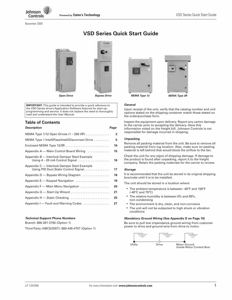
Bypass Drive NEMA Type 12 NEMA Type 3ROpen Drive
IMPORTANT:
This guide is intended to provide a quick reference to the VSD Series drive’s Application Software features for start-up, programming and service. It does not replace the need to thoroughly read and understand the User Manual.
Utility Drive Motor Ground(Inside Motor Conduit Box)
VSD Series Quick Start Guide
Powered by
Eaton’s Technology
2
For more information visit:
www.johnsoncontrols.com
LIT-1201858
November 2009
NEMA Type 1/12 Open Drives (1 – 250 HP)
Table 1: Control Wiring Instructions
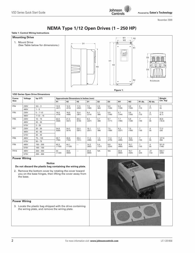
Mounting Drive
1. Mount Drive(See Table below for dimensions.)
Figure 1:
VSD Series Open Drive Dimensions
Frame
Size
Voltage hp (VT) Approximate Dimensions in Inches (mm) Weight Lbs. (kg)
H1 H2 H3 D1 D2 D3 W1 W2 R1 dia. R2 dia.
FR4 230V 3/4 – 3 12.9(327)
12.3(313)
11.5(292)
7.5 (190)
2.5 (64)
5.0 (126)
5.0 (128)
3.9 (100)
.5 (13)
.3 (7)
11 (5)
480V 1 – 5
FR5 230V 5 – 7-1/2 16.5(419)
16.0(406)
15.4(391)
8.4 (214)
2.7 (68)
5.8 (148)
5.7 (144)
3.9 (100)
.5 (13)
.3 (7)
17.9 (8.1)
480V 7-1/2 – 15
FR6 230V 10 – 15 22.0(558)
21.3(541)
20.4(519)
9.3 (237)
2.7 (68)
6.7 (171)
7.7 (195)
5.8 (148)
.7 (18)
.4 (9)
40.8(18.5)
480V 20 – 30
575V 2 – 25
FR7 230V 20 – 30 24.8(630)
24.2(614)
23.3(591)
10.1(257)
2.7 (68)
7.5 (189)
9.3 (237)
7.5 (190)
.7 (18)
.4 (9)
77.2 (35)
480V 40 – 60
575V 30 – 40
FR8 480V 75 – 125 29.7(755)
28.8(732)
28.4(721)
11.3(288)
1.3 (34)
11.0(279)
11.2(285)
10.0(255)
.7 (18)
.4 (9)
127.8(58)
575V 50 – 75
FR9 480V 150 – 200 45.3(1150)
44.1(1120)
— 14.3(362)
5.4 (137)
8.8 (224)
18.9(480)
15.7(400)
.7 (18)
.4 (9)
321.9(146)
575V 100 – 150
FR10 480V 250 – 350 44(1120)
33.5(850)
— 23.6(600)
NA NA 23.6(600)
16.7(425)
.9(23)
.47(12)
550.7(250)
575V 200 – 300
Power Wiring
Notice
Do not discard the plastic bag containing the wiring plate.
2. Remove the bottom cover by rotating the cover toward you on the base hinges, then lifting the cover away from the base.
Power Wiring
3. Locate the plastic bag shipped with the drive containing the wiring plate, and remove the wiring plate.
R2
W1W2
R2
R1
H1
H2
D1
H3
D2
D3
Knockouts
Powered by
Eaton’s Technology
VSD Series Quick Start Guide
LIT-1201858
For more information visit:
www.johnsoncontrols.com
3
November 2009
NEMA Type 1/12 Open Drives (1 – 250 HP)
Table 1: Control Wiring Instructions (continued)
Power Wiring
4. If conduit is being used, attach the wiring plate to it.
5. Pass the motor and input power wires/cables through the holes of the wiring plate.
6. If shielded cable is used, connect the shields of the input line power cable and the motor cable to the motor and power ground terminals of the VSD Series drive.
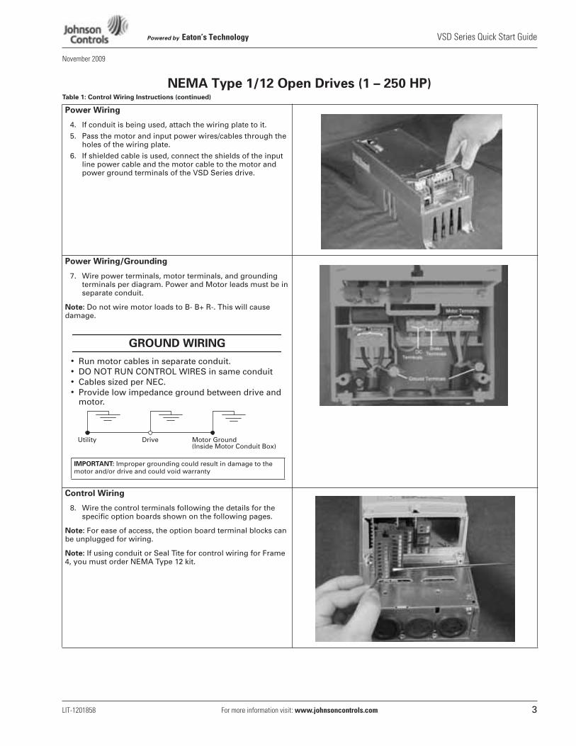
Power Wiring/Grounding
7. Wire power terminals, motor terminals, and grounding terminals per diagram. Power and Motor leads must be in separate conduit.
Note:
Do not wire motor loads to B- B+ R-. This will cause damage.
•
Run motor cables in separate conduit.
•
DO NOT RUN CONTROL WIRES in same conduit
•
Cables sized per NEC.
•
Provide low impedance ground between drive and motor.
Control Wiring
8. Wire the control terminals following the details for the specific option boards shown on the following pages.
Note:
For ease of access, the option board terminal blocks can be unplugged for wiring.
Note:
If using conduit or Seal Tite for control wiring for Frame 4, you must order NEMA Type 12 kit.
GROUND WIRING
Utility Drive Motor Ground(Inside Motor Conduit Box)
IMPORTANT: Improper grounding could result in damage to the motor and/or drive and could void warranty
VSD Series Quick Start Guide
Powered by
Eaton’s Technology
4
For more information visit:
www.johnsoncontrols.com
LIT-1201858
November 2009
NEMA Type 1/12 Open Drives (1 – 250 HP)
Table 1: Control Wiring Instructions (continued)
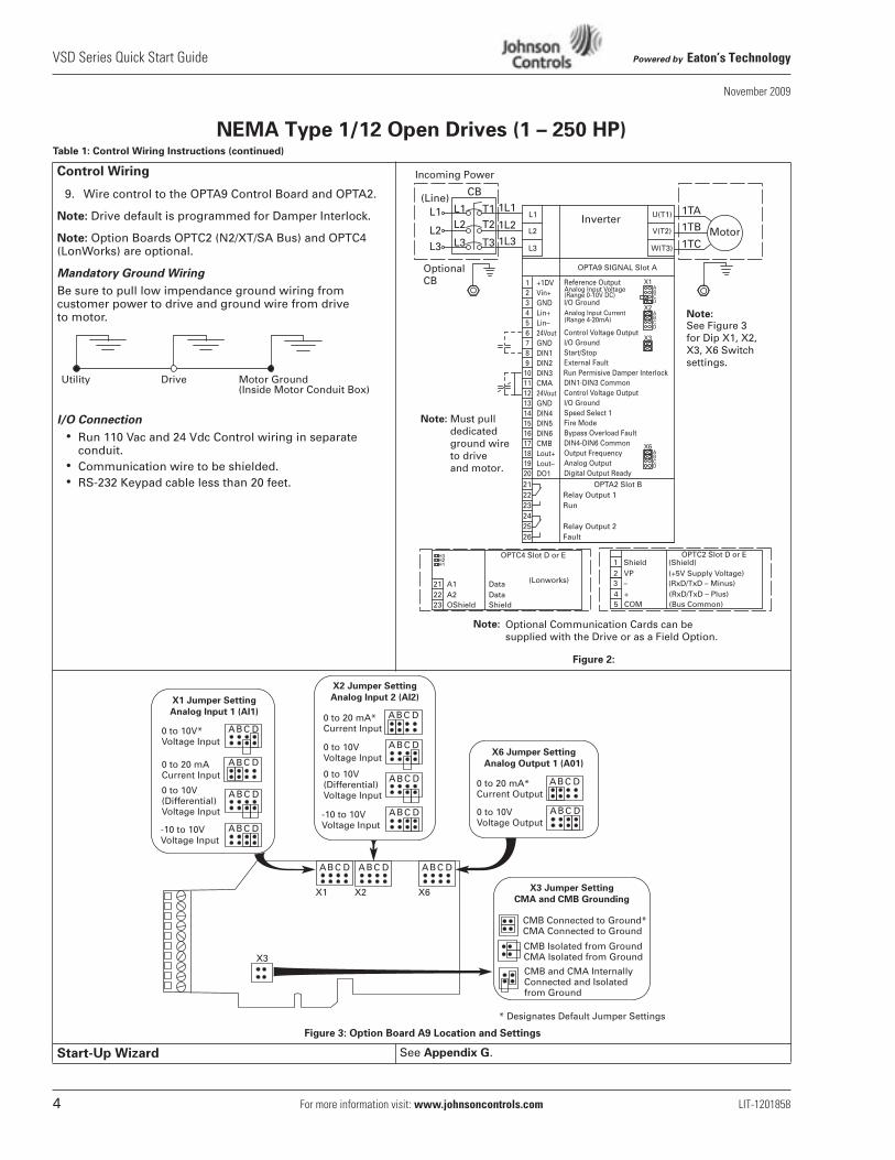
Control Wiring
9. Wire control to the OPTA9 Control Board and OPTA2.
Note:
Drive default is programmed for Damper Interlock.
Note:
Option Boards OPTC2 (N2/XT/SA Bus) and OPTC4 (LonWorks) are optional.
Mandatory Ground Wiring
Be sure to pull low impendance ground wiring from customer power to drive and ground wire from drive to motor.
I/O Connection
•
Run 110 Vac and 24 Vdc Control wiring in separate conduit.
•
Communication wire to be shielded.
•
RS-232 Keypad cable less than 20 feet.
Figure 2:
Figure 3: Option Board A9 Location and Settings
Start-Up Wizard
See
Appendix G
.
Utility Drive Motor Ground(Inside Motor Conduit Box)
Note:
+1DVVin+GNDLin+Lin–24VoutGNDDIN1DIN2DIN3CMA24VoutGNDDIN4DIN5DIN6CMBLout+Lout–DO1
1234567891011121314151617181920
Reference Output
I/O Ground
Control Voltage OutputI/O GroundStart/StopExternal Fault
DIN1-DIN3 CommonControl Voltage OutputI/O GroundSpeed Select 1Fire ModeBypass Overload FaultDIN4-DIN6 CommonOutput FrequencyAnalog OutputDigital Output Ready
Analog Input Voltage(Range 0-10V DC)
X1
X2
X3
ABCD
ABCD
Analog Input Current(Range 4-20mA)
X6ABCD
Note: Must pull dedicated ground wire to drive and motor.
Run Permisive Damper Interlock
Note: See Figure 3 for Dip X1, X2, X3, X6 Switch settings.
Optional Communication Cards can besupplied with the Drive or as a Field Option.
OptionalCB
Incoming Power
CMB and CMA InternallyConnected and Isolatedfrom Ground
X1 Jumper Setting
Analog Input 1 (AI1)
X2 Jumper Setting
Analog Input 2 (AI2)
X6 Jumper Setting
Analog Output 1 (A01)
X3 Jumper Setting
CMA and CMB Grounding
0 to 10V*Voltage Input
-10 to 10VVoltage Input
0 to 20 mACurrent Input
0 to 10V(Differential)Voltage Input
CMB Connected to Ground*CMA Connected to Ground
CMB Isolated from GroundCMA Isolated from Ground
* Designates Default Jumper Settings
0 to 20 mA*Current Input
0 to 10VVoltage Input
0 to 10V(Differential)Voltage Input
-10 to 10VVoltage Input
0 to 20 mA*Current Output
0 to 10VVoltage Output
ABC D ABC D ABC D
X1
X3
X2 X6
ABC D
ABC D
ABC D
ABC D
ABC D
ABC D
ABC D
ABC D
ABC D
ABC D
Powered by
Eaton’s Technology
VSD Series Quick Start Guide
LIT-1201858
For more information visit:
www.johnsoncontrols.com
5
November 2009
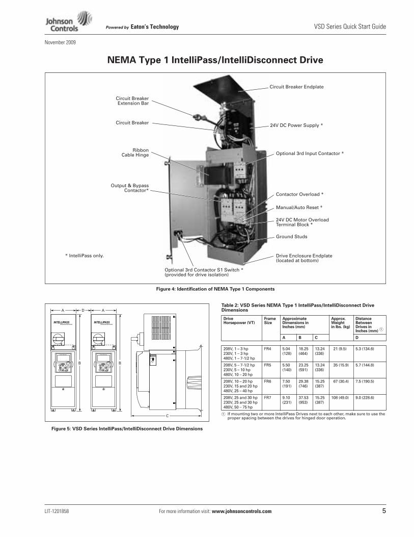
NEMA Type 1 IntelliPass/IntelliDisconnect Drive
Figure 4: Identification of NEMA Type 1 Components
Figure 5: VSD Series IntelliPass/IntelliDisconnect Drive Dimensions
Table 2: VSD Series NEMA Type 1 IntelliPass/IntelliDisconnect Drive Dimensions
�
If mounting two or more IntelliPass Drives next to each other, make sure to use the proper spacing between the drives for hinged door operation.
Optional 3rd Contactor S1 Switch *(provided for drive isolation)
Circuit BreakerExtension Bar
24V DC Power Supply *
RibbonCable Hinge Optional 3rd Input Contactor *
Output & BypassContactor*
Contactor Overload *
Manual/Auto Reset *
24V DC Motor Overload Terminal Block *
Circuit Breaker Endplate
Circuit Breaker
Ground Studs
Drive Enclosure Endplate (located at bottom)
* IntelliPass only.
Drive Horsepower (VT)
Frame Size
Approximate Dimensions in Inches (mm)
Approx.Weight in lbs. (kg)
Distance Between Drives inInches (mm)
�
A B C D
208V, 1 – 3 hp230V, 1 – 3 hp480V, 1 – 7-1/2 hp
FR4 5.04 (128)
18.25 (464)
13.24 (336)
21 (9.5) 5.3 (134.6)
208V, 5 – 7-1/2 hp230V, 5 – 10 hp480V, 10 – 20 hp
FR5 5.50 (140)
23.25 (591)
13.24 (336)
35 (15.9) 5.7 (144.8)
208V, 10 – 20 hp230V, 15 and 20 hp480V, 25 – 40 hp
FR6 7.50 (191)
29.38 (746)
15.25 (387)
67 (30.4) 7.5 (190.5)
208V, 25 and 30 hp230V, 25 and 30 hp480V, 50 – 75 hp
FR7 9.10 (231)
37.53 (953)
15.25 (387)
108 (49.0) 9.0 (228.6)
VSD Series Quick Start Guide
Powered by
Eaton’s Technology
6
For more information visit:
www.johnsoncontrols.com
LIT-1201858
November 2009
NEMA Type 1 IntelliPass/IntelliDisconnect Drive
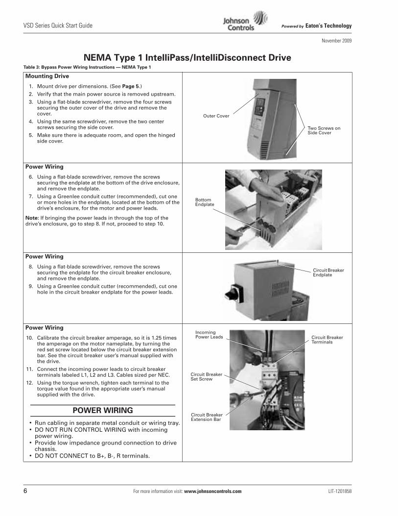
Table 3: Bypass Power Wiring Instructions — NEMA Type 1
Mounting Drive
1. Mount drive per dimensions. (See
Page 5
.)
2. Verify that the main power source is removed upstream.
3. Using a flat-blade screwdriver, remove the four screws securing the outer cover of the drive and remove the cover.
4. Using the same screwdriver, remove the two center screws securing the side cover.
5. Make sure there is adequate room, and open the hinged side cover.
Power Wiring
6. Using a flat-blade screwdriver, remove the screws securing the endplate at the bottom of the drive enclosure, and remove the endplate.
7. Using a Greenlee conduit cutter (recommended), cut one or more holes in the endplate, located at the bottom of the drive’s enclosure, for the motor and power leads.
Note:
If bringing the power leads in through the top of the drive’s enclosure, go to step 8. If not, proceed to step 10.
Power Wiring
8. Using a flat-blade screwdriver, remove the screws securing the endplate for the circuit breaker enclosure, and remove the endplate.
9. Using a Greenlee conduit cutter (recommended), cut one hole in the circuit breaker endplate for the power leads.
Power Wiring
10. Calibrate the circuit breaker amperage, so it is 1.25 times the amperage on the motor nameplate, by turning the red set screw located below the circuit breaker extension bar. See the circuit breaker user’s manual supplied with the drive.
11. Connect the incoming power leads to circuit breaker terminals labeled L1, L2 and L3. Cables sized per NEC.
12. Using the torque wrench, tighten each terminal to the torque value found in the appropriate user’s manual supplied with the drive.
•
Run cabling in separate metal conduit or wiring tray.
•
DO NOT RUN CONTROL WIRING with incoming power wiring.
•
Provide low impedance ground connection to drive chassis.
•
DO NOT CONNECT to B+, B-, R terminals.
Outer Cover
Two Screws on Side Cover
Bottom Endplate
Circuit Breaker Endplate
POWER WIRING
Circuit Breaker Set Screw
Circuit Breaker Terminals
Incoming Power Leads
Circuit Breaker Extension Bar
Powered by
Eaton’s Technology
VSD Series Quick Start Guide
LIT-1201858
For more information visit:
www.johnsoncontrols.com
7
November 2009
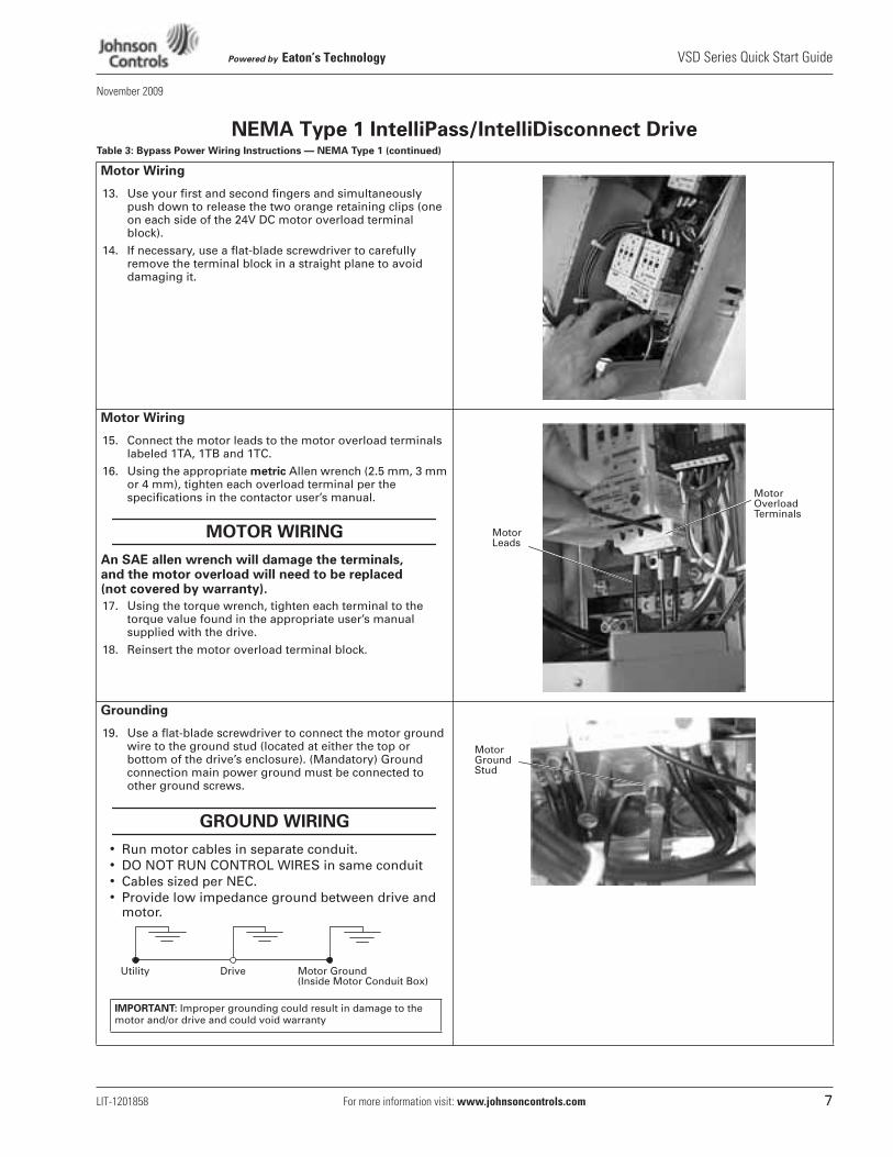
NEMA Type 1 IntelliPass/IntelliDisconnect Drive
Table 3: Bypass Power Wiring Instructions — NEMA Type 1 (continued)
Motor Wiring
13. Use your first and second fingers and simultaneously push down to release the two orange retaining clips (one on each side of the 24V DC motor overload terminal block).
14. If necessary, use a flat-blade screwdriver to carefully remove the terminal block in a straight plane to avoid damaging it.
Motor Wiring
15. Connect the motor leads to the motor overload terminals labeled 1TA, 1TB and 1TC.
16. Using the appropriate
metric
Allen wrench (2.5 mm, 3 mm or 4 mm), tighten each overload terminal per the specifications in the contactor user’s manual.
An SAE allen wrench will damage the terminals, and the motor overload will need to be replaced (not covered by warranty).
17. Using the torque wrench, tighten each terminal to the torque value found in the appropriate user’s manual supplied with the drive.
18. Reinsert the motor overload terminal block.
Grounding
19. Use a flat-blade screwdriver to connect the motor ground wire to the ground stud (located at either the top or bottom of the drive’s enclosure). (Mandatory) Ground connection main power ground must be connected to other ground screws.
•
Run motor cables in separate conduit.
•
DO NOT RUN CONTROL WIRES in same conduit
•
Cables sized per NEC.
•
Provide low impedance ground between drive and motor.
MOTOR WIRING Motor Leads
Motor Overload Terminals
GROUND WIRING
Utility Drive Motor Ground(Inside Motor Conduit Box)
IMPORTANT: Improper grounding could result in damage to the motor and/or drive and could void warranty
Motor Ground Stud
VSD Series Quick Start Guide
Powered by
Eaton’s Technology
8
For more information visit:
www.johnsoncontrols.com
LIT-1201858
November 2009
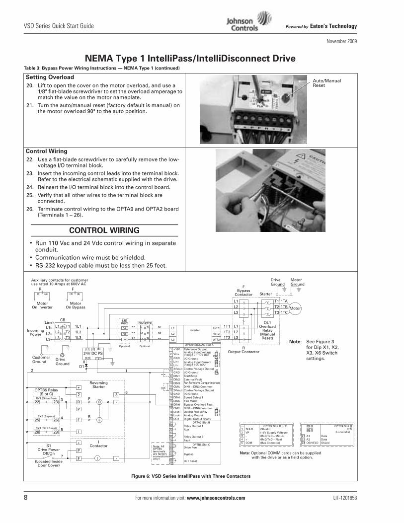
NEMA Type 1 IntelliPass/IntelliDisconnect Drive
Table 3: Bypass Power Wiring Instructions — NEMA Type 1 (continued)
Setting Overload
20. Lift to open the cover on the motor overload, and use a1/8" flat-blade screwdriver to set the overload amperage to match the value on the motor nameplate.
21. Turn the auto/manual reset (factory default is manual) on the motor overload 90° to the auto position.
Control Wiring
22. Use a flat-blade screwdriver to carefully remove the low- voltage I/O terminal block.
23. Insert the incoming control leads into the terminal block. Refer to the electrical schematic supplied with the drive.
24. Reinsert the I/O terminal block into the control board.
25. Verify that all other wires to the terminal block are connected.
26. Terminate control wiring to the OPTA9 and OPTA2 board (Terminals 1 – 26).
•
Run 110 Vac and 24 Vdc control wiring in separate conduit.
•
Communication wire must be shielded.
•
RS-232 keypad cable must be less then 25 feet.
Figure 6: VSD Series IntelliPass with Three Contactors
Auto/Manual Reset
CONTROL WIRING
DriveGround
MotorGround
Note: Optional COMM cards can be suppliedNote: with the drive or as a field option.
CustomerGround
DriveGround
Speed Select 1Fire ModeBypass Overload Fault
Start/Stop
Note: See Figure 3 for Dip X1, X2, X3, X6 Switch settings.
OptionalOptional
Powered by
Eaton’s Technology
VSD Series Quick Start Guide
LIT-1201858
For more information visit:
www.johnsoncontrols.com
9
November 2009
NEMA Type 1 IntelliPass/IntelliDisconnect Drive
able 3: Bypass Power Wiring Instructions — NEMA Type 1 (continued)
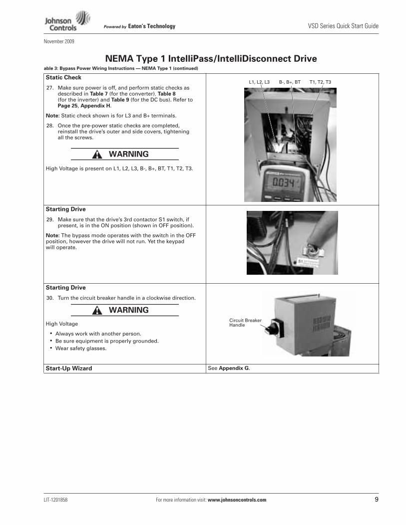
Static Check
27. Make sure power is off, and perform static checks as described in
Table 7
(for the converter)
, Table 8 (for the inverter) and Table 9 (for the DC bus). Refer to Page 25, Appendix H.
Note: Static check shown is for L3 and B+ terminals.
28. Once the pre-power static checks are completed, reinstall the drive’s outer and side covers, tightening all the screws.
High Voltage is present on L1, L2, L3, B-, B+, BT, T1, T2, T3.
Starting Drive
29. Make sure that the drive’s 3rd contactor S1 switch, if present, is in the ON position (shown in OFF position).
Note: The bypass mode operates with the switch in the OFF position, however the drive will not run. Yet the keypad will operate.
Starting Drive
30. Turn the circuit breaker handle in a clockwise direction.
High Voltage
• Always work with another person.• Be sure equipment is properly grounded.• Wear safety glasses.
Start-Up Wizard See Appendix G.
WARNING
L1, L2, L3 B-, B+, BT T1, T2, T3
WARNING
Circuit Breaker Handle
VSD Series Quick Start Guide Powered by Eaton’s Technology
10 For more information visit: www.johnsoncontrols.com LIT-1201858
November 2009
Enclosed NEMA Type 12/3R
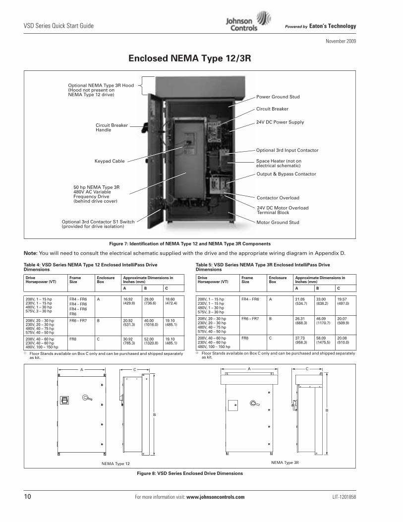
Figure 7: Identification of NEMA Type 12 and NEMA Type 3R Components
Note: You will need to consult the electrical schematic supplied with the drive and the appropriate wiring diagram in Appendix D.
Table 4: VSD Series NEMA Type 12 Enclosed IntelliPass Drive Dimensions
� Floor Stands available on Box C only and can be purchased and shipped separately as kit.
Table 5: VSD Series NEMA Type 3R Enclosed IntelliPass Drive Dimensions
� Floor Stands available on Box C only and can be purchased and shipped separately as kit.
Figure 8: VSD Series Enclosed Drive Dimensions
24V DC Power Supply
Optional 3rd Input Contactor
Space Heater (not on electrical schematic)
Output & Bypass Contactor
Circuit Breaker
50 hp NEMA Type 3R 480V AC Variable Frequency Drive (behind drive cover)
Optional 3rd Contactor S1 Switch(provided for drive isolation)
Keypad Cable
Circuit BreakerHandle
Power Ground Stud
Contactor Overload
24V DC Motor Overload Terminal Block
Motor Ground Stud
Optional NEMA Type 3R Hood(Hood not present on NEMA Type 12 drive)
Drive Horsepower (VT)
Frame Size
Enclosure Box
Approximate Dimensions in Inches (mm)
A B C
208V, 1 – 15 hp230V, 1 – 15 hp480V, 1 – 30 hp575V, 3 – 30 hp
FR4 – FR6FR4 – FR6FR4 – FR6FR6
A 16.92 (429.8)
29.00 (736.6)
18.60 (472.4)
208V, 20 – 30 hp230V, 20 – 30 hp480V, 40 – 75 hp575V, 40 – 50 hp
FR6 – FR7 B 20.92 (531.3)
40.00 (1016.0)
19.10 (485.1)
208V, 40 – 60 hp230V, 40 – 60 hp480V, 100 – 150 hp
FR8 C 30.92 (785.3)
52.00 (1320.8)
19.10 (485.1)
Drive Horsepower (VT)
Frame Size
Enclosure Box
Approximate Dimensions in Inches (mm)
A B C
208V, 1 – 15 hp230V, 1 – 15 hp480V, 1 – 30 hp575V, 3 – 30 hp
FR4 – FR6 A 21.05 (534.7)
33.00 (838.2)
19.57(497.0)
208V, 20 – 30 hp230V, 20 – 30 hp480V, 40 – 75 hp575V, 40 – 50 hp
FR6 – FR7 B 26.31 (668.3)
46.09 (1170.7)
20.07(509.9)
208V, 40 – 60 hp230V, 40 – 60 hp480V, 100 – 150 hp
FR8 C 37.73 (958.3)
58.09 (1475.5)
20.08(510.0)
NEMA Type 12
Powered by Eaton’s Technology VSD Series Quick Start Guide
LIT-1201858 For more information visit: www.johnsoncontrols.com 11
November 2009
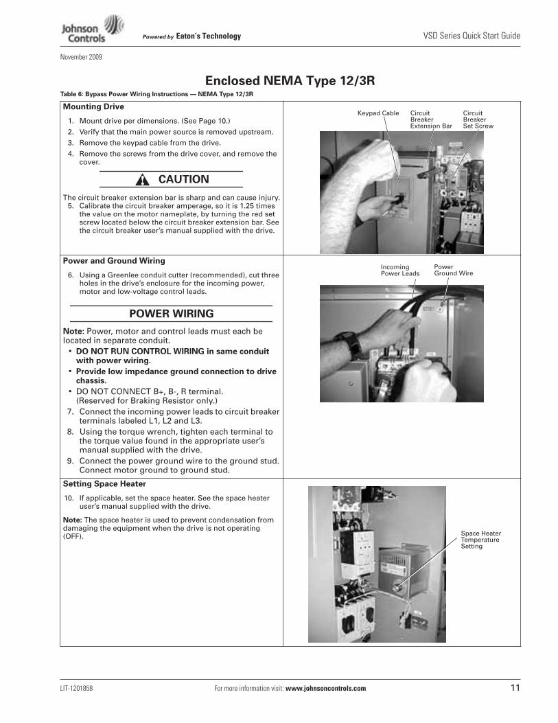
Enclosed NEMA Type 12/3RTable 6: Bypass Power Wiring Instructions — NEMA Type 12/3R
Mounting Drive
1. Mount drive per dimensions. (See Page 10.)
2. Verify that the main power source is removed upstream.
3. Remove the keypad cable from the drive.
4. Remove the screws from the drive cover, and remove the cover.
The circuit breaker extension bar is sharp and can cause injury.5. Calibrate the circuit breaker amperage, so it is 1.25 times
the value on the motor nameplate, by turning the red set screw located below the circuit breaker extension bar. See the circuit breaker user’s manual supplied with the drive.
Power and Ground Wiring
6. Using a Greenlee conduit cutter (recommended), cut three holes in the drive’s enclosure for the incoming power, motor and low-voltage control leads.
Note: Power, motor and control leads must each be located in separate conduit.
• DO NOT RUN CONTROL WIRING in same conduit with power wiring.
• Provide low impedance ground connection to drive chassis.
• DO NOT CONNECT B+, B-, R terminal. (Reserved for Braking Resistor only.)
7. Connect the incoming power leads to circuit breaker terminals labeled L1, L2 and L3.
8. Using the torque wrench, tighten each terminal to the torque value found in the appropriate user’s manual supplied with the drive.
9. Connect the power ground wire to the ground stud. Connect motor ground to ground stud.
Setting Space Heater
10. If applicable, set the space heater. See the space heater user’s manual supplied with the drive.
Note: The space heater is used to prevent condensation from damaging the equipment when the drive is not operating (OFF).
CAUTION
Circuit Breaker Set Screw
Circuit Breaker Extension Bar
Keypad Cable
POWER WIRING
Power Ground Wire
Incoming Power Leads
Space HeaterTemperature Setting
VSD Series Quick Start Guide Powered by Eaton’s Technology
12 For more information visit: www.johnsoncontrols.com LIT-1201858
November 2009
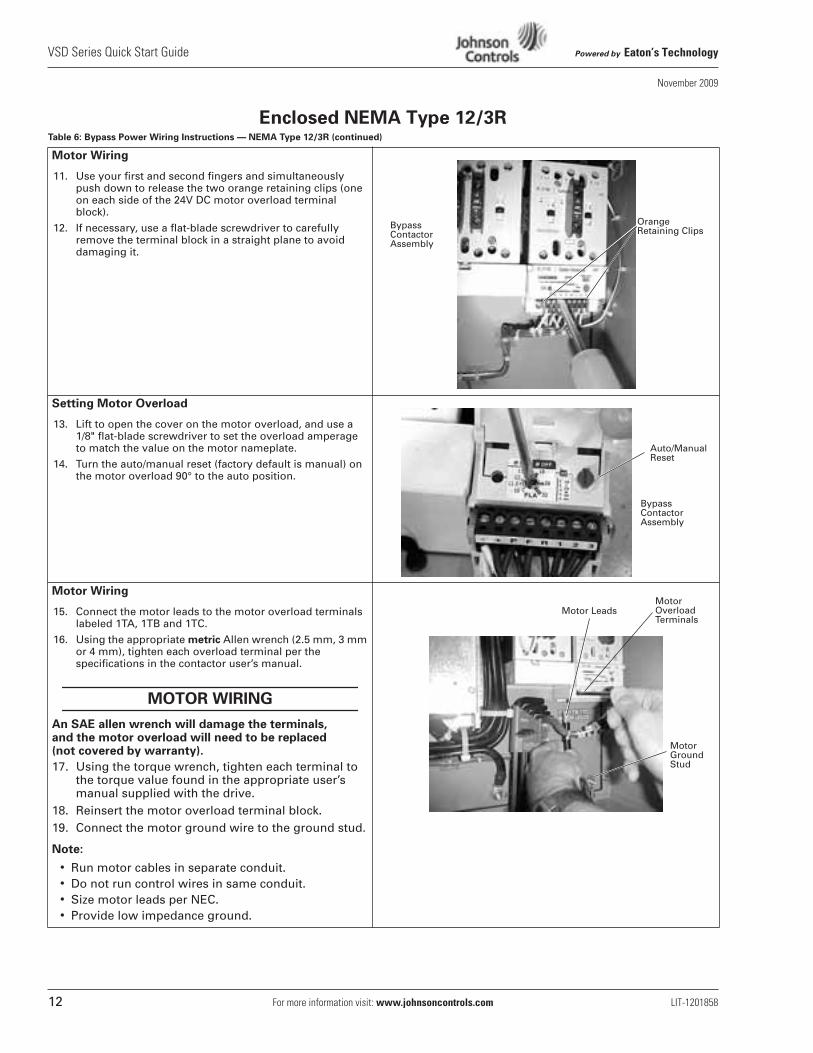
Enclosed NEMA Type 12/3RTable 6: Bypass Power Wiring Instructions — NEMA Type 12/3R (continued)
Motor Wiring
11. Use your first and second fingers and simultaneously push down to release the two orange retaining clips (one on each side of the 24V DC motor overload terminal block).
12. If necessary, use a flat-blade screwdriver to carefully remove the terminal block in a straight plane to avoid damaging it.
Setting Motor Overload
13. Lift to open the cover on the motor overload, and use a1/8" flat-blade screwdriver to set the overload amperage to match the value on the motor nameplate.
14. Turn the auto/manual reset (factory default is manual) on the motor overload 90° to the auto position.
Motor Wiring
15. Connect the motor leads to the motor overload terminals labeled 1TA, 1TB and 1TC.
16. Using the appropriate metric Allen wrench (2.5 mm, 3 mm or 4 mm), tighten each overload terminal per the specifications in the contactor user’s manual.
An SAE allen wrench will damage the terminals, and the motor overload will need to be replaced (not covered by warranty).
17. Using the torque wrench, tighten each terminal to the torque value found in the appropriate user’s manual supplied with the drive.
18. Reinsert the motor overload terminal block.19. Connect the motor ground wire to the ground stud.
Note:
• Run motor cables in separate conduit.• Do not run control wires in same conduit.• Size motor leads per NEC.• Provide low impedance ground.
OrangeRetaining Clips
Bypass Contactor Assembly
Auto/Manual Reset
Bypass Contactor Assembly
MOTOR WIRING
Motor LeadsMotor Overload Terminals
Motor Ground Stud
Powered by Eaton’s Technology VSD Series Quick Start Guide
LIT-1201858 For more information visit: www.johnsoncontrols.com 13
November 2009
Enclosed NEMA Type 12/3RTable 6: Bypass Power Wiring Instructions — NEMA Type 12/3R (continued)
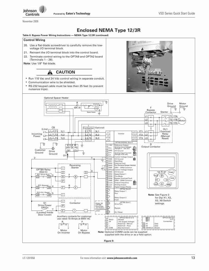
Control Wiring
20. Use a flat-blade screwdriver to carefully remove the low-voltage I/O terminal block.
21. Reinsert the I/O terminal block into the control board.
22. Terminate control wiring to the OPTA9 and OPTA2 board (Terminals 1 – 26).
Note: Use 1/8" flat-blade.
• Run 110 Vac and 24 Vdc control wiring in separate conduit.• Communication wire to be shielded.• RS-232 keypad cable must be less then 25 feet (to prevent
nuisance trips).
Figure 9:
CAUTION
DriveGround
MotorGround
Note: Optional COMM cards can be suppliedNote: supplied with the drive or as a field option.
CustomerGround
DriveGround
(Optional)
Speed Select 1Fire ModeBypass Overload Fault
Start/Stop
Note: See Figure 3 for Dip X1, X2, X3, X6 Switch settings.
(DC 2)
R
FAN
Space Heater
Optional Spacer Heater
VSD Series Quick Start Guide Powered by Eaton’s Technology
14 For more information visit: www.johnsoncontrols.com LIT-1201858
November 2009
Enclosed NEMA Type 12/3RTable 6: Bypass Power Wiring Instructions — NEMA Type 12/3R (continued)
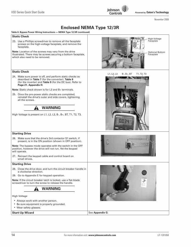
Static Check
23. Use a Phillips screwdriver to remove all the faceplate screws on the high-voltage faceplate, and remove the faceplate.
Note: Location of the screws may vary from the drive illustrated. There may be screws securing a bottom faceplate, which also need to be removed.
Static Check
24. Make sure power is off, and perform static checks as described in Table 7 (for the converter), Table 8 (for the inverter) and Table 9 (for the DC bus). Refer to Page 21, Appendix H.
Note: Static check shown is for L3 and B+ terminals.
25. Once the pre-power static checks are completed, reinstall the drive’s outer and side covers, tightening all the screws.
High Voltage is present on L1, L2, L3, B-, B+, BT, T1, T2, T3.
Starting Drive
26. Make sure that the drive’s 3rd contactor S1 switch, if present, is in the ON position (shown in OFF position).
Note: The bypass mode operates with the switch in the OFF position, however the drive will not run. Yet the keypad will operate.
27. Reinsert the keypad cable and control board on small drives.
Starting Drive
28. Close the drive door, and turn the circuit breaker handle in a clockwise direction.
29. Go to Appendix E for keypad operation.
Note: If the circuit breaker latch is locked, use a flat-blade screwdriver to turn the screw to release the handle.
High Voltage
• Always work with another person.• Be sure equipment is properly grounded.• Wear safety glasses.
Start-Up Wizard See Appendix G.
High-Voltage Faceplate
Optional Bottom Faceplate
WARNING
L1, L2, L3 B-, B+, BT T1, T2, T3
WARNING
Powered by Eaton’s Technology VSD Series Quick Start Guide
LIT-1201858 For more information visit: www.johnsoncontrols.com 15
November 2009
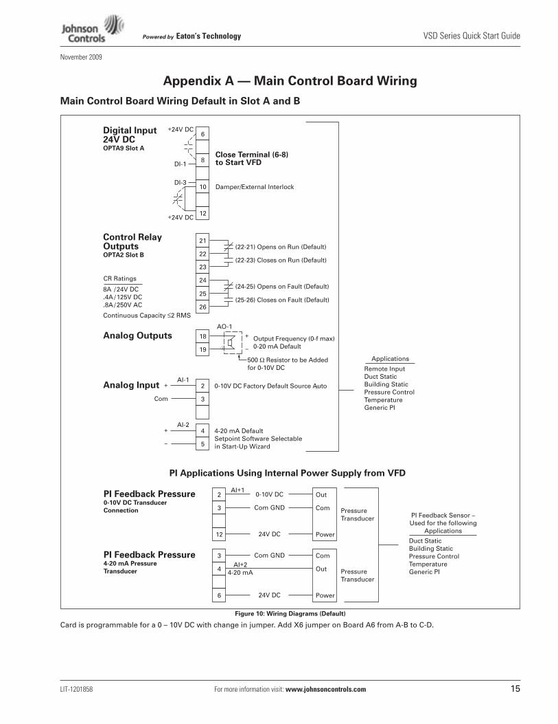
Appendix A — Main Control Board Wiring
Main Control Board Wiring Default in Slot A and B
Figure 10: Wiring Diagrams (Default)
Card is programmable for a 0 – 10V DC with change in jumper. Add X6 jumper on Board A6 from A-B to C-D.
Digital Input 24V DCOPTA9 Slot A
+24V DC
+24V DC
6
Control RelayOutputsOPTA2 Slot B
8A / 24V DC.4A / 125V DC.8A / 250V AC
Continuous Capacity ≤2 RMS
CR Ratings
21
22
23
24
25
26
(22-21) Opens on Run (Default)
Remote InputDuct StaticBuilding StaticPressure ControlTemperatureGeneric PI
Applications
Analog OutputsAO-1
18
19
Analog InputAI-1
2
3
+
–
–
Output Frequency (0-f max)0-20 mA Default
0-10V DC Factory Default Source Auto
500 Ω Resistor to be Added for 0-10V DC
(22-23) Closes on Run (Default)
(24-25) Opens on Fault (Default)
(25-26) Closes on Fault (Default)
8
10
12
Close Terminal (6-8)to Start VFD
PressureTransducer
Damper/External Interlock
+
Com
AI-2
DI-1
DI-3
4
5
4-20 mA DefaultSetpoint Software Selectablein Start-Up Wizard
+
PI Applications Using Internal Power Supply from VFD
PI Feedback Sensor –Used for the following
Applications
PI Feedback Pressure0-10V DC Transducer
Connection
PI Feedback Pressure4-20 mA Pressure
Transducer
2
3
12
Out
Com
Power
0-10V DCAI+1
AI+24-20 mA
Com GND
PressureTransducer
24V DCDuct StaticBuilding StaticPressure ControlTemperatureGeneric PI
3
4
6
Com
Out
Power
Com GND
24V DC
VSD Series Quick Start Guide Powered by Eaton’s Technology
16 For more information visit: www.johnsoncontrols.com LIT-1201858
November 2009
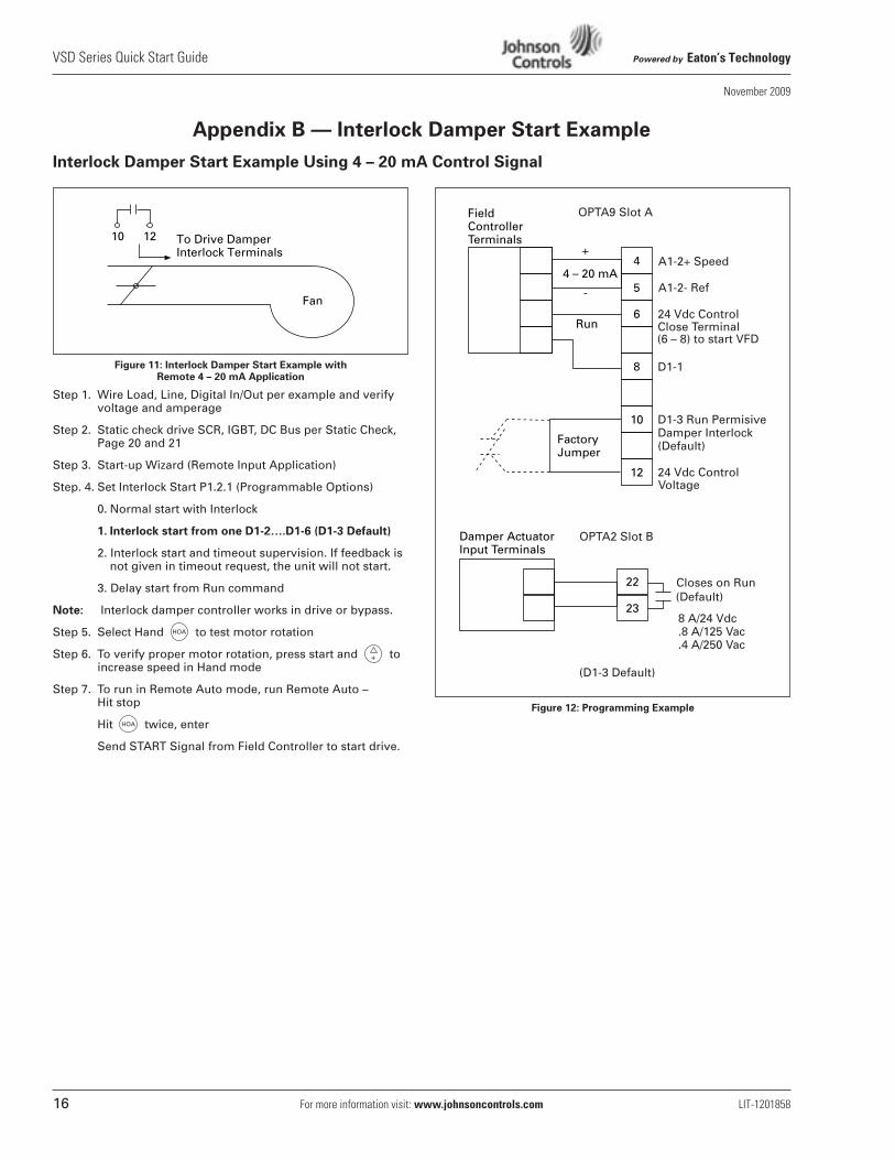
Appendix B — Interlock Damper Start Example
Interlock Damper Start Example Using 4 – 20 mA Control Signal
Figure 11: Interlock Damper Start Example with Remote 4 – 20 mA Application
Step 1. Wire Load, Line, Digital In/Out per example and verifyvoltage and amperage
Step 2. Static check drive SCR, IGBT, DC Bus per Static Check, Page 20 and 21
Step 3. Start-up Wizard (Remote Input Application)
Step. 4. Set Interlock Start P1.2.1 (Programmable Options)
0. Normal start with Interlock
1. Interlock start from one D1-2….D1-6 (D1-3 Default)
2. Interlock start and timeout supervision. If feedback is not given in timeout request, the unit will not start.
3. Delay start from Run command
Note: Interlock damper controller works in drive or bypass.
Step 5. Select Hand to test motor rotation
Step 6. To verify proper motor rotation, press start and toincrease speed in Hand mode
Step 7. To run in Remote Auto mode, run Remote Auto – Hit stop
Hit twice, enter
Send START Signal from Field Controller to start drive.
Figure 12: Programming Example
To Drive Damper Interlock Terminals
10 12
Fan
HOA
+
HOA
4
5
6
8
10
12
4 – 20 mA
+
-
Run
FieldControllerTerminals
FactoryJumper
22
23
Damper ActuatorInput Terminals
A1-2+ Speed
A1-2- Ref
24 Vdc ControlClose Terminal(6 – 8) to start VFD
D1-1
D1-3 Run PermisiveDamper Interlock(Default)
24 Vdc ControlVoltage
Closes on Run(Default)
8 A/24 Vdc.8 A/125 Vac.4 A/250 Vac
(D1-3 Default)
OPTA2 Slot B
OPTA9 Slot A
Powered by Eaton’s Technology VSD Series Quick Start Guide
LIT-1201858 For more information visit: www.johnsoncontrols.com 17
November 2009
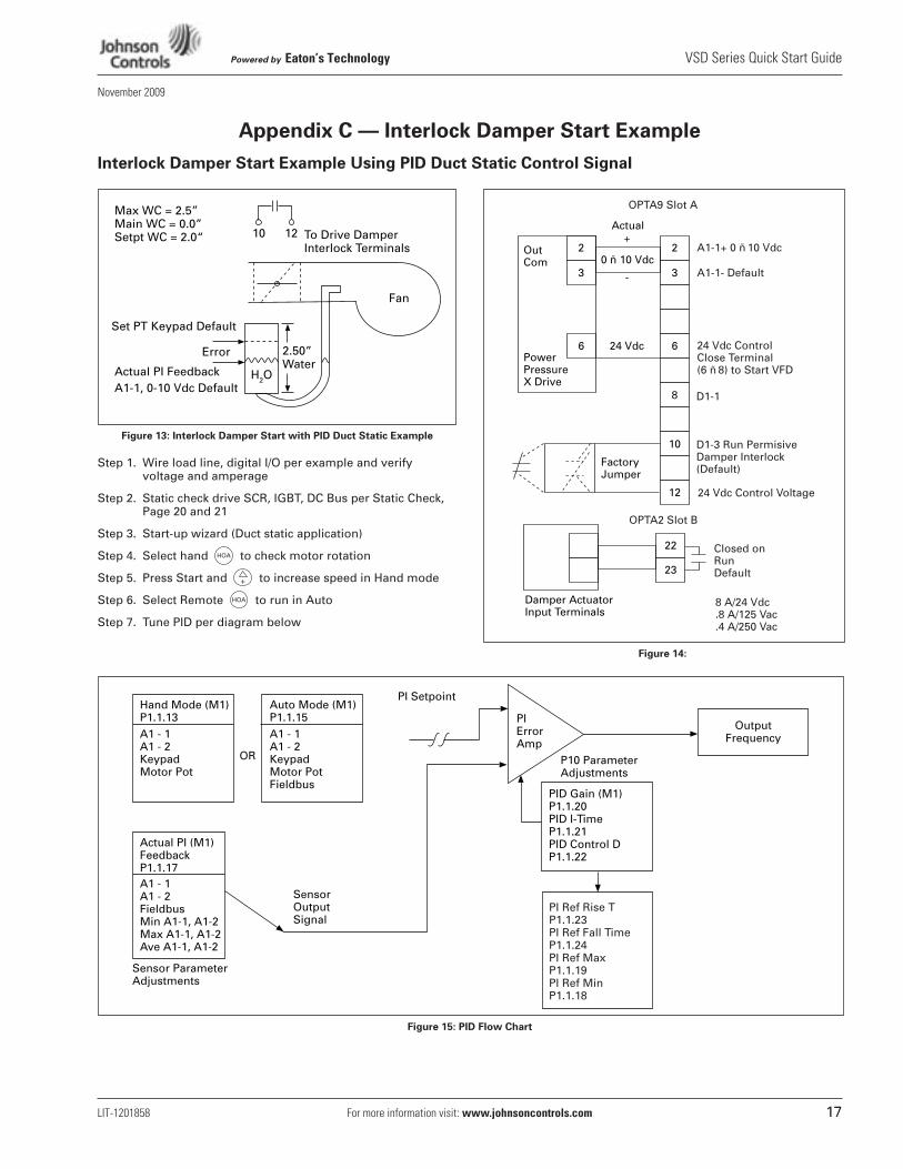
Appendix C — Interlock Damper Start Example
Interlock Damper Start Example Using PID Duct Static Control Signal
Figure 13: Interlock Damper Start with PID Duct Static Example
Step 1. Wire load line, digital I/O per example and verify voltage and amperage
Step 2. Static check drive SCR, IGBT, DC Bus per Static Check, Page 20 and 21
Step 3. Start-up wizard (Duct static application)
Step 4. Select hand to check motor rotation
Step 5. Press Start and to increase speed in Hand mode
Step 6. Select Remote to run in Auto
Step 7. Tune PID per diagram below
Figure 14:
Figure 15: PID Flow Chart
Max WC = 2.5”Main WC = 0.0”Setpt WC = 2.0“ To Drive Damper
Interlock Terminals10 12
Fan
Set PT Keypad Default
Actual PI FeedbackA1-1, 0-10 Vdc Default
2.50”Water
H2O
Error
HOA
+
HOA
2
3
2
3
66
8
10
12
0 ñ 10 Vdc
Actual+
-
24 Vdc
OutCom
PowerPressureX Drive
FactoryJumper
22
23
A1-1+ 0 ñ 10 Vdc
A1-1- Default
24 Vdc ControlClose Terminal(6 ñ 8) to Start VFD
D1-1
D1-3 Run PermisiveDamper Interlock(Default)
24 Vdc Control Voltage
Closed onRunDefault
8 A/24 Vdc.8 A/125 Vac.4 A/250 Vac
OPTA9 Slot A
OPTA2 Slot B
Damper ActuatorInput Terminals
Hand Mode (M1)P1.1.13A1 - 1A1 - 2KeypadMotor Pot
Actual PI (M1) FeedbackP1.1.17 A1 - 1A1 - 2FieldbusMin A1-1, A1-2Max A1-1, A1-2Ave A1-1, A1-2
Auto Mode (M1)P1.1.15A1 - 1A1 - 2KeypadMotor PotFieldbus
PID Gain (M1)P1.1.20PID I-TimeP1.1.21PID Control DP1.1.22
OutputFrequency
PIErrorAmp
PI Setpoint
PI Ref Rise TP1.1.23PI Ref Fall TimeP1.1.24PI Ref MaxP1.1.19PI Ref MinP1.1.18
OR P10 ParameterAdjustments
Sensor OutputSignal
Sensor ParameterAdjustments
VSD Series Quick Start Guide Powered by Eaton’s Technology
18 For more information visit: www.johnsoncontrols.com LIT-1201858
November 2009
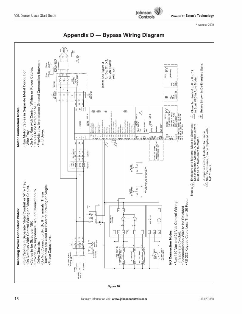
Appendix D — Bypass Wiring Diagram
Figure 16:
Inco
min
g P
ow
er
Co
nn
ecti
on
No
tes:
Mo
tor
Co
nn
ecti
on
No
tes:
I/O
Co
nn
ecti
on
No
tes:
Ru
n 1
10 V
ac a
nd
24
Vd
c C
on
tro
l Wir
ing
in
Sep
arat
e C
on
du
it.
Co
mm
un
icat
ion
Wir
e to
be
Sh
ield
ed.
RS
-232
Key
pad
Cab
le L
ess
Th
an 2
0 Fe
et.
No
tes:
En
clo
sure
an
d M
oto
r(s)
Mu
st b
e G
rou
nd
ed.
See
Inst
ruct
ion
Man
ual
. A c
on
tin
uo
us
wir
em
ust
be
run
fro
m d
rive
to
mo
tor.
Jum
per
is F
acto
ry In
stal
led
to
En
able
Sta
rt P
erm
issi
ve. C
an b
e R
epla
ced
wit
hN
/C C
on
tact
.
Clo
se T
erm
inal
s 6
to 8
or
8 to
12
to S
tart
VFD
in A
uto
Mo
de.
Rel
ays
Sh
ow
n in
De-
En
erg
ized
Sta
te.
1 2
3 4
Dri
veG
rou
nd
Mo
tor
Gro
un
d
Cu
sto
mer
Gro
un
dD
rive
Gro
un
d
Ru
n C
ablin
g in
Sep
arat
e M
etal
Co
nd
uit
or
Wir
e Tr
ay.
Do
No
t R
un
Wit
h C
on
tro
l Wir
ing
or
Mo
tor
Cab
les.
Cab
les
to b
e S
ized
per
NE
C.
Pro
vid
e Lo
w Im
ped
ance
Gro
un
d C
on
nec
tio
n t
oD
rive
Ch
assi
s.D
o N
ot
Co
nn
ect
to B
+, B
-, R
Ter
min
als.
Th
ese
Term
inal
s ar
e U
sed
fo
r E
xter
nal
Bra
kin
g o
r S
ing
le-
Ph
ase
Cap
acit
ors
.
Ru
n M
oto
r C
able
s in
Sep
arat
e M
etal
Co
nd
uit
or
Wir
e Tr
ay.
Do
No
t R
un
wit
h C
on
tro
l Wir
ing
or
Po
wer
Cab
les.
Cab
les
to b
e S
ized
per
NE
C.
Pro
vid
e Lo
w Im
ped
ance
Gro
un
d C
on
nec
tio
n B
etw
een
an
d D
rive
.
+1D
V
Vin+
GN
D
Lin+
Lin–
24Vo
ut
GN
D
DIN
1
DIN
2
DIN
3
CM
A
24Vo
ut
GN
D
DIN
4
DIN
5
DIN
6
CM
B
Lout
+
Lout
–
DO
1
Ref
eren
ce O
utpu
t
I/O G
roun
d
Con
trol
Vol
tage
Out
put
I/O G
roun
d
Exte
rnal
Fau
lt
DIN
1-D
IN3
Com
mon
Con
trol
Vol
tage
Out
put
I/O G
roun
d
Byp
ass
Ove
rloa
d Fa
ult
DIN
4-D
IN6
Com
mon
Out
put F
requ
ency
Ana
log
Out
put
Dig
ital O
utpu
t Rea
dy
X1
X2
X3
A B C D A B C D
X6
A B C D
Ana
log
Inpu
t Vol
tage
(Ran
ge 0
-10V
DC
)
Ana
log
Inpu
t Cur
rent
(Ran
ge 4
-20m
A)
Spe
ed S
elec
t 1
Fire
Mod
e
Sta
rt/S
top
Op
tio
nal
Op
tio
nal
No
te: S
ee F
igu
re 3
fo
r D
ip X
1, X
2, X
3, X
6 S
wit
ch s
etti
ng
s.
Powered by Eaton’s Technology VSD Series Quick Start Guide
LIT-1201858 For more information visit: www.johnsoncontrols.com 19
November 2009
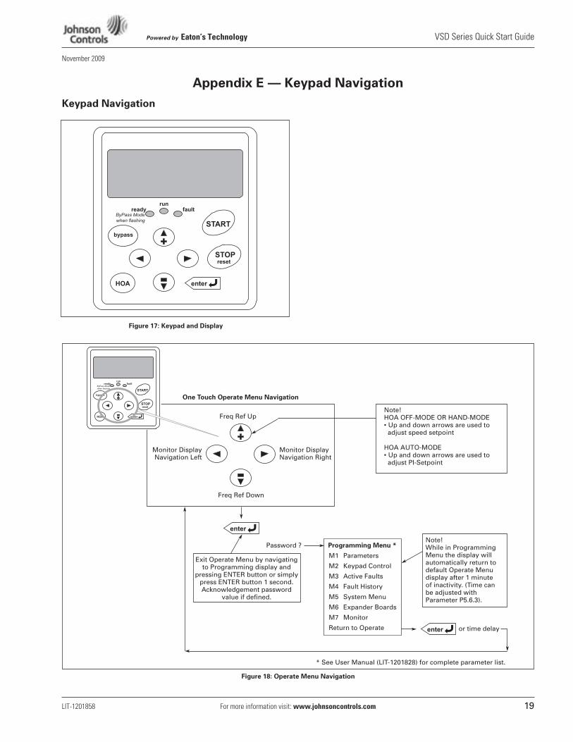
Appendix E — Keypad Navigation
Keypad Navigation
Figure 17: Keypad and Display
Figure 18: Operate Menu Navigation
One Touch Operate Menu Navigation
Freq Ref Up
Password ?
Freq Ref Down
Exit Operate Menu by navigatingto Programming display and
pressing ENTER button or simplypress ENTER button 1 second.Acknowledgement password
value if defined.
Monitor DisplayNavigation Left
Monitor DisplayNavigation Right
Programming Menu *
Note!HOA OFF-MODE OR HAND-MODE• Up and down arrows are used to adjust speed setpoint
HOA AUTO-MODE• Up and down arrows are used to adjust PI-Setpoint
Note!While in ProgrammingMenu the display will automatically return todefault Operate Menudisplay after 1 minuteof inactivity. (Time canbe adjusted withParameter P5.6.3).
or time delay
M1 Parameters
M2 Keypad Control
M3 Active Faults
M4 Fault History
M5 System Menu
M6 Expander Boards
M7 Monitor
Return to Operate
* See User Manual (LIT-1201828) for complete parameter list.
VSD Series Quick Start Guide Powered by Eaton’s Technology
20 For more information visit: www.johnsoncontrols.com LIT-1201858
November 2009
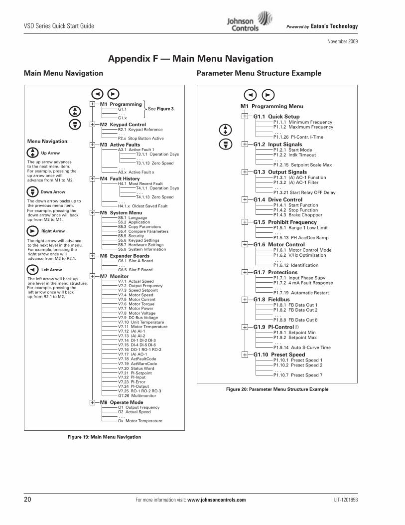
Appendix F — Main Menu Navigation
Main Menu Navigation
Figure 19: Main Menu Navigation
Parameter Menu Structure Example
Figure 20: Parameter Menu Structure Example
M1 Programming
M2 Keypad Control
M3 Active Faults
M6 Expander Boards
M7 Monitor
G1.1 . . .
. . .R2.1 Keypad Reference
P2.x Stop Button Active
A3.1 Active Fault 1T3.1.1 Operation Days . . .T3.1.13 Zero Speed
A3.x Active Fault x
V7.1 Actual SpeedV7.2 Output FrequencyV7.3 Speed Setpoint
G1.x
G6.1 Slot A Board . . .G6.5 Slot E Board
+
+
+
+
V7.4 Motor SpeedV7.5 Motor CurrentV7.6 Motor TorqueV7.7 Motor PowerV7.8 Motor VoltageV7.9 DC-Bus VoltageV7.10 Unit TemperatureV7.11 Motor TemperatureV7.12 (A) AI-1V7.13 (A) AI-2V7.14 DI-1 DI-2 DI-3V7.15 DI-4 DI-5 DI-6V7.16 DO-1 RO-1 RO-2V7.17 (A) AO-1V7.18 ActFaultCode
Menu Navigation:
The up arrow advances to the next menu item.For example, pressing theup arrow once willadvance from M1 to M2.
The down arrow backs up to
The right arrow will advance
the previous menu item.
to the next level in the menu.
The left arrow will back up one level in the menu structure.
For example, pressing the down arrow once will back up from M2 to M1.
For example, pressing the right arrow once will advance from M2 to R2.1.
For example, pressing the left arrow once will back up from R2.1 to M2.
V7.19 ActWarnCodeV7.20 Status WordV7.21 PI-SetpointV7.22 PI-Input
V7.24 PI-OutputV7.23 PI-Error
M8 Operate Mode O1 Output FrequencyO2 Actual Speed . . .Ox Motor Temperature
+G7.26 MultimonitorV7.25 RO-1 RO-2 RO-3
+
+
M5 System MenuS5.1 LanguageS5.2 ApplicationS5.3 Copy Parameters
+
S5.4 Compare ParametersS5.5 SecurityS5.6 Keypad SettingsS5.7 Hardware SettingsS5.8 System Information
. . .
M4 Fault HistoryH4.1 Most Recent Fault
T4.1.1 Operation Days . . .T4.1.13 Zero Speed
H4.1.x Oldest Saved Fault . . .
Up Arrow
Down Arrow
Right Arrow
Left Arrow
See Figure 3.
G1.1 Quick Setup
G1.2 Input Signals
G1.3 Output Signals
G1.6 Motor Control
G1.7 Protections
G1.8 Fieldbus
P1.1.1 Minimum Frequency
. . .
. . .
P1.2.1 Start ModeP1.2.2 Intlk Timeout
P1.2.15 Setpoint Scale Max
P1.3.1 (A) AO-1 Function
P1.7.1 Input Phase SupvP1.7.2 4 mA Fault Response . . .
P1.1.26 PI-Contr. I-Time
P1.6.1 Motor Control Mode
. . .P1.6.12 Identification
P1.8.1 FB Data Out 1P1.8.2 FB Data Out 2 . . .P1.8.8 FB Data Out 8
+
+
+
P1.3.2 (A) AO-1 Filter
P1.3.21 Start Relay OFF Delay . . .
P1.4.1 Start FunctionP1.4.2 Stop FunctionP1.4.3 Brake Choppper
P1.7.19 Automatic Restart
P1.1.2 Maximum Frequency
+
+
+
+
G1.9 PI-Control
G1.10 Preset Speed
P1.9.1 Setpoint MinP1.9.2 Setpoint Max . . .P1.9.14 Auto S-Curve Time
+
P1.10.1 Preset Speed 1P1.10.2 Preset Speed 2 . . .P1.10.7 Preset Speed 7
+
M1 Programming Menu
P1.6.2 V/Hz Optimization
G1.5 Prohibit FrequencyP1.5.1 Range 1 Low Limit . . .
+
P1.5.13 PH Acc/Dec Ramp
G1.4 Drive Control
Powered by Eaton’s Technology VSD Series Quick Start Guide
LIT-1201858 For more information visit: www.johnsoncontrols.com 21
November 2009
Appendix G — Start-Up Wizard
Start-Up Wizard
Duct Static, Building Static, Pressure Control, Temperature Control, Generic PI
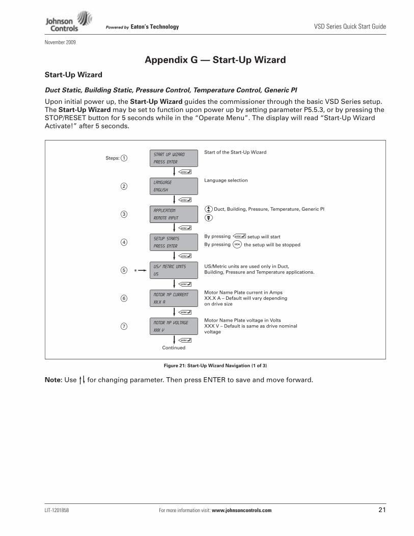
Upon initial power up, the Start-Up Wizard guides the commissioner through the basic VSD Series setup. The Start-Up Wizard may be set to function upon power up by setting parameter P5.5.3, or by pressing the STOP/RESET button for 5 seconds while in the “Operate Menu”. The display will read “Start-Up Wizard Activate!” after 5 seconds.
Figure 21: Start-Up Wizard Navigation (1 of 3)
Note: Use for changing parameter. Then press ENTER to save and move forward.
start up wizard
press enter
Start of the Start-Up Wizard
language
english
Language selection
application
remote input
Duct, Building, Pressure, Temperature, Generic PI
setup starts
press enter
By pressing
By pressing
setup will start
the setup will be stopped
US/ metric units
us*
motor Np current
XX.X A
Motor Name Plate current in AmpsXX.X A – Default will vary dependingon drive size
US/Metric units are used only in Duct, Building, Pressure and Temperature applications.
motor Np voltage
XXX V
Motor Name Plate voltage in VoltsXXX V – Default is same as drive nominalvoltage
Continued
1Steps:
2
3
4
5
6
7
VSD Series Quick Start Guide Powered by Eaton’s Technology
22 For more information visit: www.johnsoncontrols.com LIT-1201858
November 2009
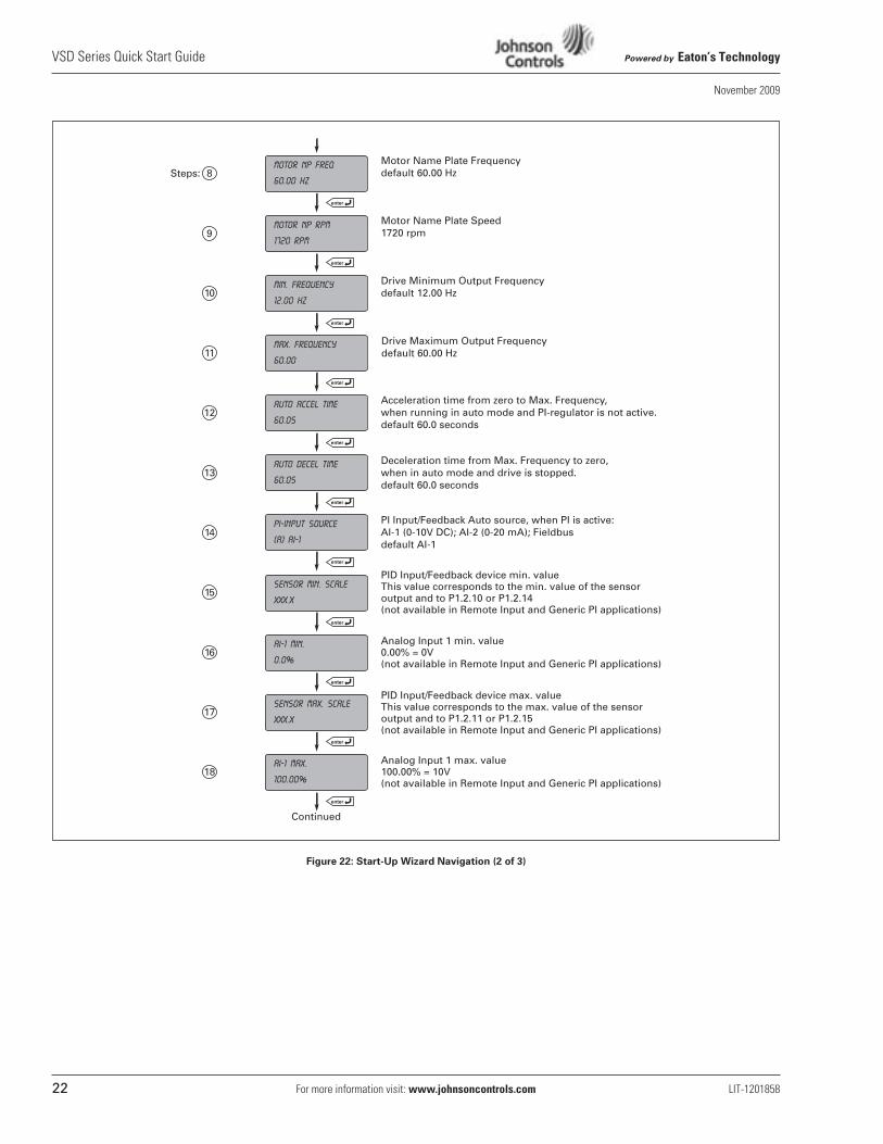
Figure 22: Start-Up Wizard Navigation (2 of 3)
motor NP rpm
1720 rpm
Motor Name Plate Speed1720 rpm
min. frequency
12.00 Hz
Drive Minimum Output Frequencydefault 12.00 Hz
max. frequency
60.00
Drive Maximum Output Frequencydefault 60.00 Hz
AUTO ACCEL Time
60.0s
Acceleration time from zero to Max. Frequency,when running in auto mode and PI-regulator is not active.default 60.0 seconds
AUTO DECEL time
60.0s
Deceleration time from Max. Frequency to zero,when in auto mode and drive is stopped.default 60.0 seconds
PI-input source
(a) ai-1
PI Input/Feedback Auto source, when PI is active:AI-1 (0-10V DC); AI-2 (0-20 mA); Fieldbusdefault AI-1
motor NP freq
60.00 Hz
Motor Name Plate Frequencydefault 60.00 Hz
sensor min. scale
XXX.X
PID Input/Feedback device min. valueThis value corresponds to the min. value of the sensoroutput and to P1.2.10 or P1.2.14(not available in Remote Input and Generic PI applications)
AI-1 Min.
0.0%
Analog Input 1 min. value 0.00% = 0V(not available in Remote Input and Generic PI applications)
8Steps:
9
10
11
12
13
14
15
16
sensor max. scale
XXX.X
Analog Input 1 max. value100.00% = 10V(not available in Remote Input and Generic PI applications)
17
AI-1 Max.
100.00%
PID Input/Feedback device max. valueThis value corresponds to the max. value of the sensoroutput and to P1.2.11 or P1.2.15(not available in Remote Input and Generic PI applications)
Continued
18
Powered by Eaton’s Technology VSD Series Quick Start Guide
LIT-1201858 For more information visit: www.johnsoncontrols.com 23
November 2009
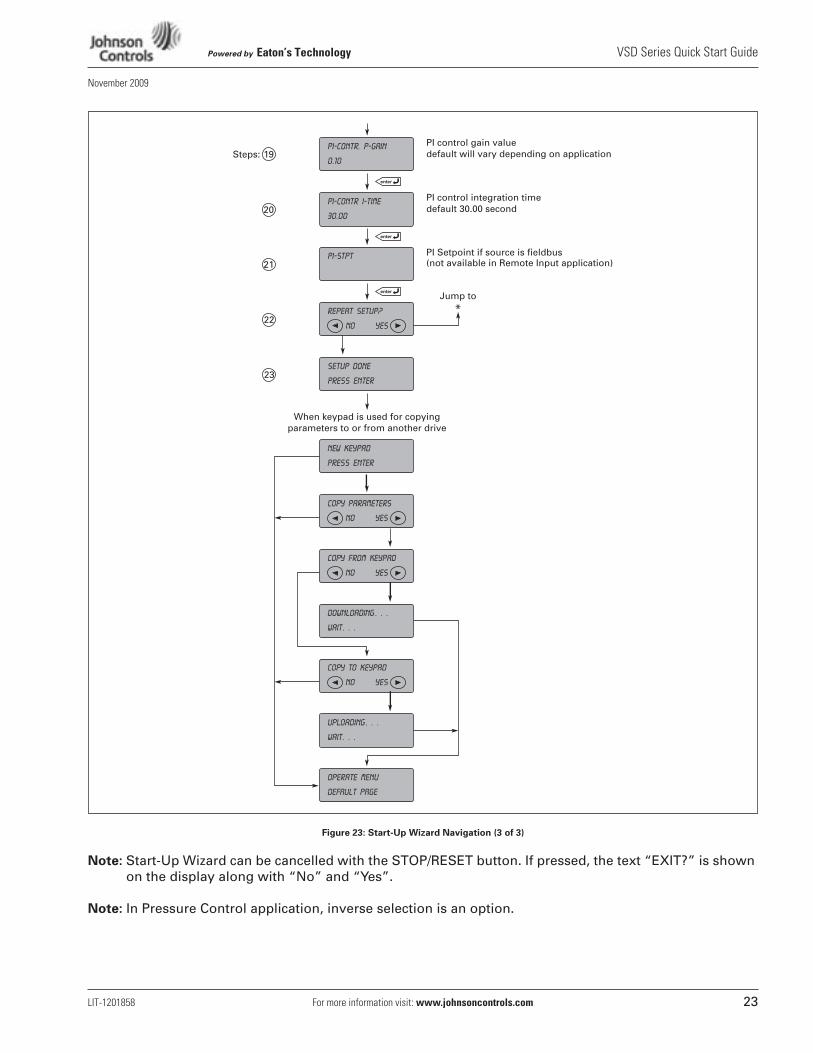
Figure 23: Start-Up Wizard Navigation (3 of 3)
Note: Start-Up Wizard can be cancelled with the STOP/RESET button. If pressed, the text “EXIT?” is shown on the display along with “No” and “Yes”.
Note: In Pressure Control application, inverse selection is an option.
copy from keypad
NO yes
PI-contr I-time
30.00
PI control integration timedefault 30.00 second
repeat setup?
NO yes
Jump to
*
setup done
press enter
new keypad
press enter
When keypad is used for copying parameters to or from another drive
PI-contr. p-gain
0.10
PI control gain valuedefault will vary depending on application
downloading . . .
wait. . .
copy to keypad
NO yes
operate menu
default page
uploading . . .
wait. . .
copy parameters
NO yes
PI-stpt PI Setpoint if source is fieldbus(not available in Remote Input application)
19Steps:
20
21
22
23
VSD Series Quick Start Guide Powered by Eaton’s Technology
24 For more information visit: www.johnsoncontrols.com LIT-1201858
November 2009
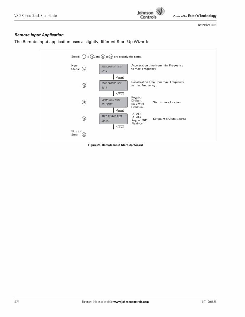
Remote Input Application
The Remote Input application uses a slightly different Start-Up Wizard:
Figure 24: Remote Input Start-Up Wizard
deceleration time
60 s
Deceleration time from max. Frequencyto min. Frequency
Start source location
Set point of Auto Source
start srce auto
DI-1 start
KeypadDI-StartI/O 3 wireFieldbus
stpt source auto
(a) ai-1
(A) AI-1(A) AI-2Keypad StPtFieldbus
acceleration time
60 s
Acceleration time from min. Frequencyto max. Frequency12
1 4 6 10Steps: to , and to are exactly the same.
NewSteps:
Skip toStep:
13
14
15
22
Powered by Eaton’s Technology VSD Series Quick Start Guide
LIT-1201858 For more information visit: www.johnsoncontrols.com 25
November 2009
Appendix H — Static Checking
Static Checking
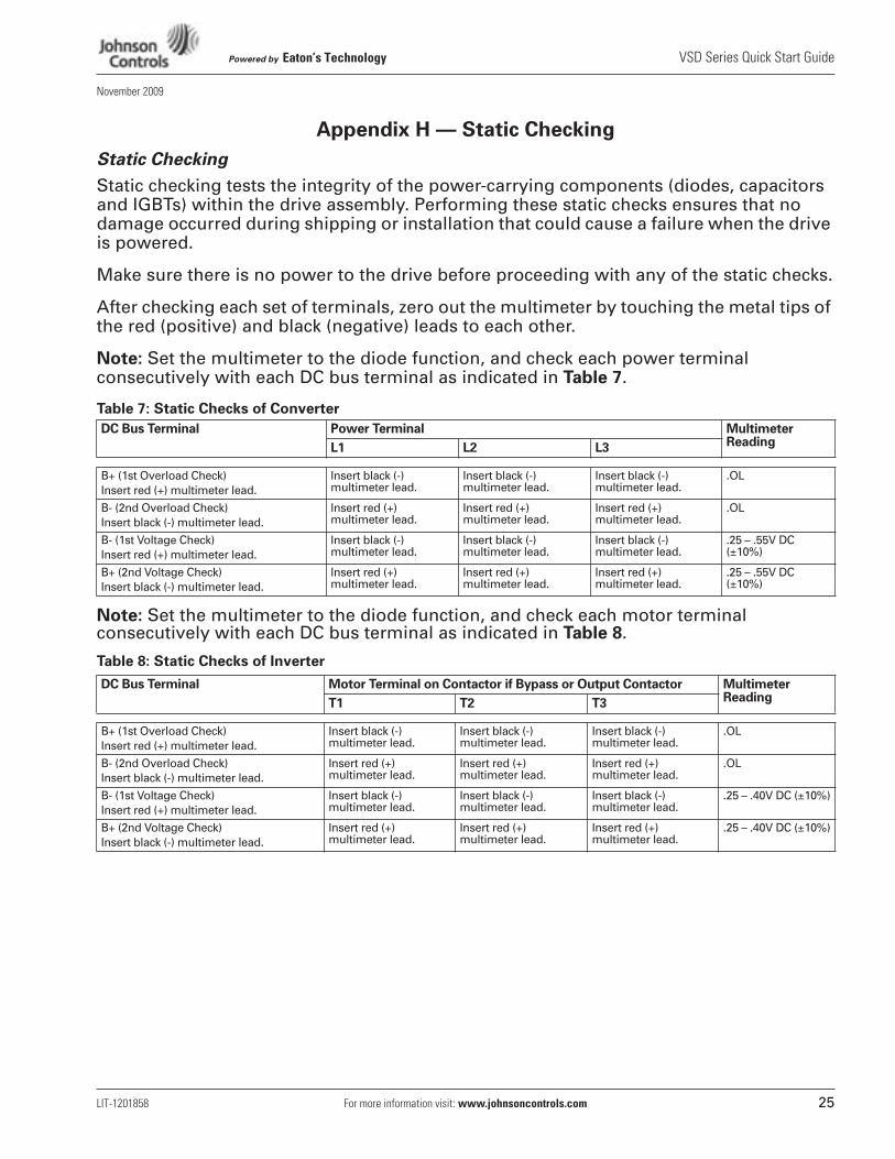
Static checking tests the integrity of the power-carrying components (diodes, capacitors and IGBTs) within the drive assembly. Performing these static checks ensures that no damage occurred during shipping or installation that could cause a failure when the drive is powered.
Make sure there is no power to the drive before proceeding with any of the static checks.
After checking each set of terminals, zero out the multimeter by touching the metal tips of the red (positive) and black (negative) leads to each other.
Note: Set the multimeter to the diode function, and check each power terminal consecutively with each DC bus terminal as indicated in Table 7.
Table 7: Static Checks of Converter
Note: Set the multimeter to the diode function, and check each motor terminal consecutively with each DC bus terminal as indicated in Table 8.
Table 8: Static Checks of Inverter
DC Bus Terminal Power Terminal Multimeter ReadingL1 L2 L3
B+ (1st Overload Check)Insert red (+) multimeter lead.
Insert black (-) multimeter lead.
Insert black (-) multimeter lead.
Insert black (-) multimeter lead.
.OL
B- (2nd Overload Check)Insert black (-) multimeter lead.
Insert red (+) multimeter lead.
Insert red (+) multimeter lead.
Insert red (+) multimeter lead.
.OL
B- (1st Voltage Check)Insert red (+) multimeter lead.
Insert black (-) multimeter lead.
Insert black (-) multimeter lead.
Insert black (-) multimeter lead.
.25 – .55V DC (±10%)
B+ (2nd Voltage Check)Insert black (-) multimeter lead.
Insert red (+) multimeter lead.
Insert red (+) multimeter lead.
Insert red (+) multimeter lead.
.25 – .55V DC (±10%)
DC Bus Terminal Motor Terminal on Contactor if Bypass or Output Contactor Multimeter ReadingT1 T2 T3
B+ (1st Overload Check)Insert red (+) multimeter lead.
Insert black (-) multimeter lead.
Insert black (-) multimeter lead.
Insert black (-) multimeter lead.
.OL
B- (2nd Overload Check)Insert black (-) multimeter lead.
Insert red (+) multimeter lead.
Insert red (+) multimeter lead.
Insert red (+) multimeter lead.
.OL
B- (1st Voltage Check)Insert red (+) multimeter lead.
Insert black (-) multimeter lead.
Insert black (-) multimeter lead.
Insert black (-) multimeter lead.
.25 – .40V DC (±10%)
B+ (2nd Voltage Check)Insert black (-) multimeter lead.
Insert red (+) multimeter lead.
Insert red (+) multimeter lead.
Insert red (+) multimeter lead.
.25 – .40V DC (±10%)
VSD Series Quick Start Guide Powered by Eaton’s Technology
26 For more information visit: www.johnsoncontrols.com LIT-1201858
November 2009
Appendix H — Static Checking, continued
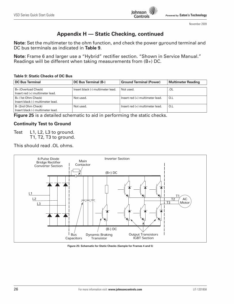
Note: Set the multimeter to the ohm function, and check the power gµround terminal and DC bus terminals as indicated in Table 9.
Note: Frame 6 and larger use a “Hybrid” rectifier section. “Shown in Service Manual.” Readings will be different when taking measurements from (B+) DC.
Table 9: Static Checks of DC Bus
Figure 25 is a detailed schematic to aid in performing the static checks.
Continuity Test to Ground
Test L1, L2, L3 to ground.T1, T2, T3 to ground.
This should read .OL ohms.
Figure 25: Schematic for Static Checks (Sample for Frames 4 and 5)
DC Bus Terminal DC Bus Terminal (B-) Ground Terminal (Power) Multimeter Reading
B+ (Overload Check)Insert red (+) multimeter lead.
Insert black (-) multimeter lead. Not used. .OL
B+ (1st Ohm Check)Insert black (-) multimeter lead.
Not used. Insert red (+) multimeter lead. O.L
B- (2nd Ohm Check)Insert black (-) multimeter lead.
Not used. Insert red (+) multimeter lead. O.L
Powered by Eaton’s Technology VSD Series Quick Start Guide
LIT-1201858 For more information visit: www.johnsoncontrols.com 27
November 2009
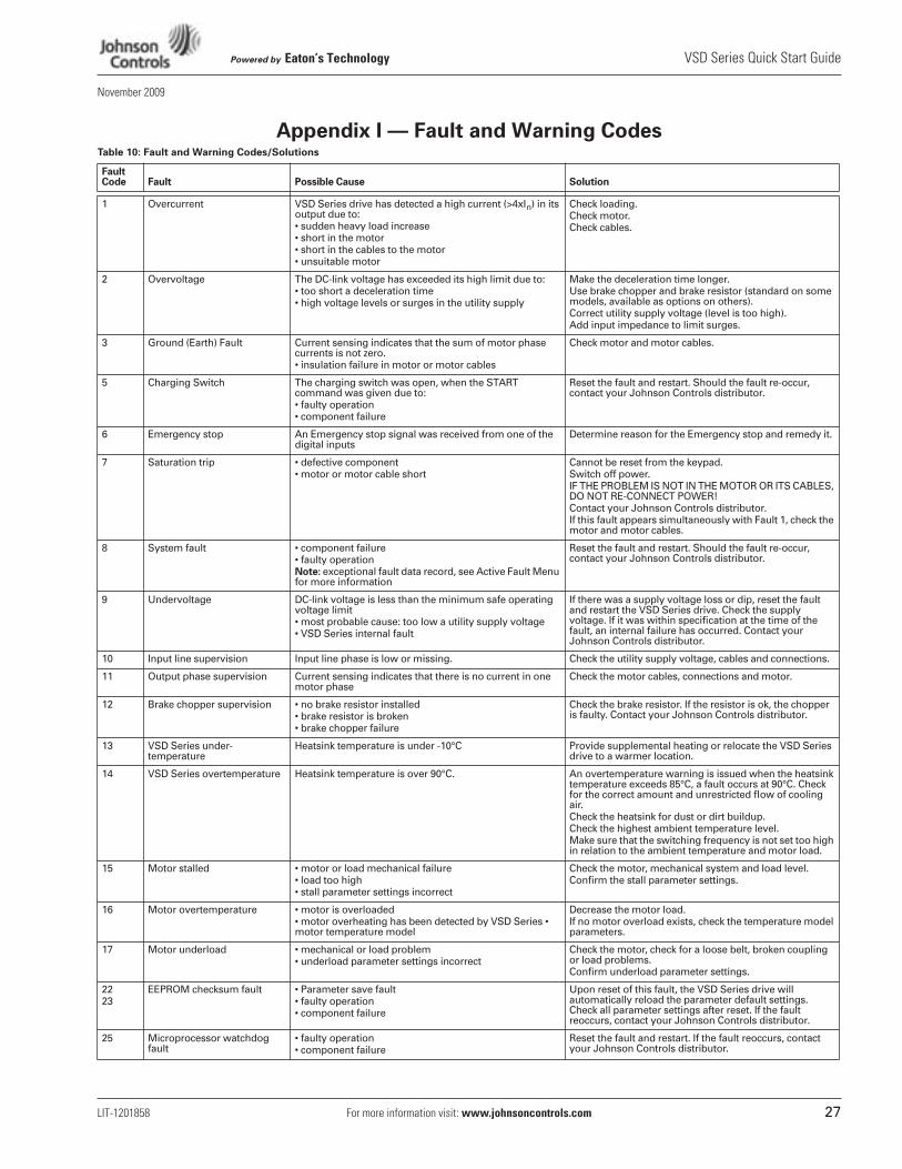
Appendix I — Fault and Warning CodesTable 10: Fault and Warning Codes/Solutions
Fault Code Fault Possible Cause Solution
1 Overcurrent VSD Series drive has detected a high current (>4xIn) in its output due to:• sudden heavy load increase• short in the motor• short in the cables to the motor• unsuitable motor
Check loading.Check motor.Check cables.
2 Overvoltage The DC-link voltage has exceeded its high limit due to:• too short a deceleration time• high voltage levels or surges in the utility supply
Make the deceleration time longer. Use brake chopper and brake resistor (standard on some models, available as options on others).Correct utility supply voltage (level is too high).Add input impedance to limit surges.
3 Ground (Earth) Fault Current sensing indicates that the sum of motor phase currents is not zero.• insulation failure in motor or motor cables
Check motor and motor cables.
5 Charging Switch The charging switch was open, when the START command was given due to:• faulty operation• component failure
Reset the fault and restart. Should the fault re-occur, contact your Johnson Controls distributor.
6 Emergency stop An Emergency stop signal was received from one of the digital inputs
Determine reason for the Emergency stop and remedy it.
7 Saturation trip • defective component• motor or motor cable short
Cannot be reset from the keypad. Switch off power.IF THE PROBLEM IS NOT IN THE MOTOR OR ITS CABLES, DO NOT RE-CONNECT POWER!Contact your Johnson Controls distributor.If this fault appears simultaneously with Fault 1, check the motor and motor cables.
8 System fault • component failure• faulty operationNote: exceptional fault data record, see Active Fault Menu for more information
Reset the fault and restart. Should the fault re-occur, contact your Johnson Controls distributor.
9 Undervoltage DC-link voltage is less than the minimum safe operating voltage limit• most probable cause: too low a utility supply voltage• VSD Series internal fault
If there was a supply voltage loss or dip, reset the fault and restart the VSD Series drive. Check the supply voltage. If it was within specification at the time of the fault, an internal failure has occurred. Contact your Johnson Controls distributor.
10 Input line supervision Input line phase is low or missing. Check the utility supply voltage, cables and connections.
11 Output phase supervision Current sensing indicates that there is no current in one motor phase
Check the motor cables, connections and motor.
12 Brake chopper supervision • no brake resistor installed• brake resistor is broken• brake chopper failure
Check the brake resistor. If the resistor is ok, the chopper is faulty. Contact your Johnson Controls distributor.
13 VSD Series under-temperature
Heatsink temperature is under -10°C Provide supplemental heating or relocate the VSD Series drive to a warmer location.
14 VSD Series overtemperature Heatsink temperature is over 90°C. An overtemperature warning is issued when the heatsink temperature exceeds 85°C, a fault occurs at 90°C. Check for the correct amount and unrestricted flow of cooling air.Check the heatsink for dust or dirt buildup.Check the highest ambient temperature level.Make sure that the switching frequency is not set too high in relation to the ambient temperature and motor load.
15 Motor stalled • motor or load mechanical failure• load too high• stall parameter settings incorrect
Check the motor, mechanical system and load level.Confirm the stall parameter settings.
16 Motor overtemperature • motor is overloaded• motor overheating has been detected by VSD Series • motor temperature model
Decrease the motor load.If no motor overload exists, check the temperature model parameters.
17 Motor underload • mechanical or load problem• underload parameter settings incorrect
Check the motor, check for a loose belt, broken coupling or load problems.Confirm underload parameter settings.
2223
EEPROM checksum fault • Parameter save fault• faulty operation• component failure
Upon reset of this fault, the VSD Series drive will automatically reload the parameter default settings. Check all parameter settings after reset. If the fault reoccurs, contact your Johnson Controls distributor.
25 Microprocessor watchdog fault
• faulty operation• component failure
Reset the fault and restart. If the fault reoccurs, contact your Johnson Controls distributor.
Controls Group507 E. Michigan StreetP.O. Box 423Milwaukee, WI 53201
© 2009 Johnson ControlsAll Rights ReservedPrinted in USALIT-1201858www.johnsoncontrols.comNovember 2009
Powered by Eaton’s Technology
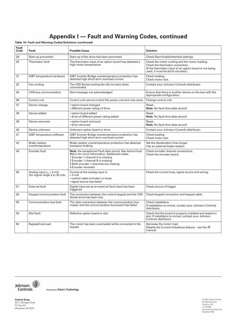
Appendix I — Fault and Warning Codes, continuedTable 10: Fault and Warning Codes/Solutions (continued)
Fault Code Fault Possible Cause Solution
26 Start-up prevented Start-up of the drive has been prevented. Check Start Enable/Interlock settings.
29 Thermistor fault The thermistor input of an option board has detected a high motor temperature
Check the motor cooling and the motor loading.Check the thermistor connection.(If the thermistor input of an option board is not being used, it must be short-circuited.)
31 IGBT temperature hardware IGBT Inverter Bridge overtemperature protection has detected high short term overload current
Check loading.Check motor size.
32 Fan cooling The VSD Series cooling fan did not start when commanded
Contact your Johnson Controls distributor.
34 CAN bus communication Sent message not acknowledged Ensure that there is another device on the bus with the appropriate configuration.
36 Control unit Control unit cannot control the power unit and vise-versa Change control unit.
37 Device change • option board changed• different power rating of drive
Reset.Note: No fault time data record!
38 Device added • option board added• drive of different power rating added
Reset.Note: No fault time data record!
39 Device removed • option board removed• drive removed
Reset.Note: No fault time data record!
40 Device unknown Unknown option board or drive Contact your Johnson Controls distributor.
41 IGBT temperature software IGBT Inverter Bridge overtemperature protection has detected high short term overload current
Check loading.Check motor size.
42 Brake resistor overtemperature
Brake resistor overtemperature protection has detected excessive braking
Set the deceleration time longer.Use an external brake resistor.
43 Encoder fault Note: the exceptional Fault data record. See Active Fault Menu for more information. Additional codes:1 Encoder 1 channel A is missing2 Encoder 1 channel B is missing3 Both encoder 1 channels are missing4 Encoder reversed
Check encoder channel connections.Check the encoder board.
50 Analog input Iin < 4 mA (for signal range 4 to 20 mA)
Current at the analog input is < 4 mA• control cable is broken or loose• signal source has failed
Check the current loop, signal source and wiring.
51 External fault Digital input set as an external fault input has been triggered.
Check source of trigger.
52 Keypad communication fault The connection between the control keypad and the VSD Series drive has been lost.
Check keypad connection and keypad cable.
53 Communication bus fault The data connection between the communication bus master and the communication bus board has failed
Check installation.If installation is correct, contact your Johnson Controls distributor.
54 Slot fault Defective option board or slot Check that the board is properly installed and seated in slot. If installation is correct, contact your Johnson Controls distributor.
82 BypassOverLoad The motor has been overloaded while connected to the bypass
Decrease the motor load.Disable the Current Imbalance feature – see the IT. manual.