vs 220/ 400/ 400-viti/ vs600
TRANSCRIPT

VS 220/ 400/ 400-VITI/ VS600
Operator's manualEdition 08.2014Date of printing 09.2015Language EN- USAMachine number 1001 Type VN223/ VN224/ VN225/ VN226Document Number VN70051799-1

VS 220/ 400/ 400-VITI/ VS600
Machine identificationYour supplier needs your machine’s particulars in order to assist you as soon as possible.Please enter this information here.
Name
Working width
Weight
Machine number
Accessories
Address of thesupplier
Manufacturer's address
Kverneland Group Nieuw-Vennep B.V. Hoofdweg 1278 NL-2153 LR Nieuw-VennepThe Netherlands
Author's right and copyright are vested in the Kverneland Group Nieuw-Vennep B.V., The Netherlands. Making copies, acquisition in other media,translation and use of excerpts or portions of this manual without the express permission of Kverneland is prohibited. All rights reserved. Thecontents of this manual may be changed without notice. Subject to technical changes.
ft
_________ lbs
VN_ _ _ _

Content
3
Content
Preface ....................................................... 4Target group of this manual 4Meaning of symbols 5
Safety ......................................................... 6For your safety 6Other guidelines 6Safety labels 7Safety regulations 11
Getting familiar with the machine ........... 26Applications of the machine 26SuperFlow spreading system 26Spreading pattern 27Spreading pattern 28Adjust carefully 30Technical specifications 33
Assembly instruction ............................... 35Inspection of the supplied machine 35General 35Assembly VS220-330 37VS400- 500 44VS 600 - 1000 50
Before first use ......................................... 60Tractor provisions 60Mounting the coupling shaft 61
Hitching to the tractor .............................. 64Connecting the machine 65
To be done before spreading .................. 71Online spreading chart service 71
To be done before spreading .................. 75Finding the correct setting for your spreading work 75Setting the spreader 80Fine application 84Filling 89Calibration test 91Check the spreading pattern (tray test) 94
Driving on the road ................................... 102Before taking the road 102Preparing the machine to be transported 103
Use on the land .......................................... 104Adjusting the machine 105Set driving paths 107Spreading 109Border spreading 111Failure and stoppage 116
Storing the machine .................................. 119Cleaning 119Disconnecting the machine 120
Maintenance ............................................... 122Maintenance intervals 124Lubricate with oil and grease 125Coupling shaft 125Manual or hydraulic operation pin joint 126Spreading unit 126Torques 129Checking the hydraulic system 130Control of the pendulum mechanism 133Spreading spout check 135
Accessories ............................................... 136
Trouble shooting ....................................... 142Troubleshooting table 142
Falling into disuse ..................................... 144
Liability ....................................................... 145Liability 145Complaints regarding product completeness 146Guarantee 146
EGC declaration of conformity ................ 147
Notes .......................................................... 148
Index ........................................................... 149

Preface
4
Preface
Target group of this manual
This operator’s manual is intended for agrarians and others trained inworking in the field of agriculture, people that are competent tooperate these machine, and who have knowledge of assemblyactivities, and familiarity with assembling equipment.
For your safetyEnsure that you are familiar with the contents of this manual beforeyou start using or assembling the implement. This will ensure that youobtain an optimum result and are working safely. See paragraph »Safety regulations« on page 11.Should you have any questions or if anything is unclear, pleasecontact the manufacturer.Make sure that this manual is available to all persons who will beworking with this machine. In this way, you will:
• avoid accidents,
• respect the warranty conditions,
• always have a good functioning machine in good working order.
For the employer
• All personnel who operate this machine must be authorized to do so in terms of the knowledge and experience.
• All personnel are to be trained in the use of the machine regularly (at least once a year). Untrained or unauthorized individuals are not permitted to use the machinery.
• You are responsible for the safe operation and maintenance of your machine. You must ensure that you and anyone else who is going to operate, maintain or work around the unit be familiar with the operating and maintenance procedures and related safety information as mentioned in this manual.
• You are responsible for providing personal protective gear to personnel who use the machine or who are performing maintenance or repairs on it as appropriate. This includes: safety goggles, safety shoes, safety gloves, etc.

Preface
5
Meaning of symbols
Various symbols are used to provide a clear understanding of the text.These are explained below
• A dot is placed before lists.
A triangle marks tasks you have to perform.
An arrow refers to a different place in the text.
In addition, we use pictograms to help you easily find certain textsections.
INDICATION The words "Tip" and "Hint" are followed by tips or hints for operation.
The spanner indicates tips for assembly or adjustment work.
A star indicates that examples will follow that are intended to clarify thetext.
All directional rotations are to be interpreted when facing in directionof travel.
California Proposition 65
\ WARNINGEngine exhaust, some of its constituents, certain machinecomponents and fluids, contain or emit chemicals known to theState of California to cause cancer and birth defects or otherreproductive harm
\ SAFETY FIRSTThis symbol, the industry's "Safety Alert Symbol", is usedthroughout this manual and on labels on the machine itself to warnof the possibility of personal injury. Read these instructionscarefully. It is essential that you read the instructions and safetyregulations before you attempt to assemble or use this unit.
\ DANGERIndicates an imminently hazardous situation which, if not avoided,will result in death or serious injury.
\ WARNINGIndicates a potentially hazardous situation which, if not avoided,could result in death or serious injury.
\ CAUTIONIndicates a potentially hazardous situation which, if not avoided,could result in minor or moderate injury.

Safety
6
Safety
For your safety Know your equipment and it's limitations.
Read this entire manual before attempting start and operate the units.
In this chapter you will find general safety instructions. In every nextchapter you will find more specific safety instructions not describedhere.
Do not risk injury or death by ignoring good safety instructions.Many risks can happen when working with agricultural machines.Avoid accidents! Do not take risks! Be alert!Think safety! Work in safety!
Disregard of the 'Safety instructions', inadequate maintenance, use ofthe machine other than for its intended purpose, overloading orunauthorized modification of the machine, renders the manufacturer'swarranty and responsibility void.
Familiarise yourself with the function of all machine controls and thesafety instructions, prior to any usage of the machine.
Incorrect use of the machine may lead to dangerous situations. Forthis reason, you should always work carefully and never under timepressure.
Other guidelines Comply with the rulesIn addition to the instructions above you should comply with thefollowing:
• measures to prevent accidents,
• general safety instructions, occupational health requirements and road traffic regulations,
• instructions in this operator’s manual,
• Rules regarding use, maintenance and repairs.

Safety
7
Safety labels Various safety labels have been affixed to the machine for safetyreasons. Do not remove them! Always follow the instructions suppliedand be alert to possible dangers.Always keep the safety labels clean and clearly legible. Replacesafety labels that are missing, damaged or have become illegible. Iforiginal parts on which a safety label or sign was installed are fixed, besure that the replacement part also displays the current safety labels.
VS 220 - 330
CAUTION
READ THE MANUAL• THE MACHINE MUST NOT BE
USED BEFORE READING THE OPERATING MANUAL.
TO AVOID FATAL OR SERIOUS INJURY:READ THE MANUAL FIRST V
F166
6151
2
DANGERPARTS EJECTED AT SPEED• PARTS MAY BECOME DETACHED AND
EJECTED AT SPEED.
TO AVOID DEATH OR SERIOUS INJURY:KEEP IN A SAFE DISTANCE V
F166
6149
3
WARNING
VERTICAL MOVEMENT• RISK OF INJURY BY LIFTING
OR LOWERING MACHINEPARTS.
TO AVOID DEATH OR SERIOUS INJURY:KEEP OUT OF THIS AREA
VF1
6661
574
WARNING
AREA OF RISK• RISK OF DEATH OR INJURY ON
COUPLING, UNCOUPLING OR OPERATING.
TO AVOID DEATH OR SERIOUS INJURY:NO PERSONS IN THIS AREA
VF1
6661
498
WARNING
UNEXPECTED MOVEMENT• MACHINE PARTS MAY STILL
ROTATE AFTER ENGINE ISSWITCHED OFF.
TO AVOID FATAL OR SERIOUS INJURY:KEEP AWAY UNTIL PARTS STOP MOVING V
F166
6151
0
WARNING
INADVERTENT OPERATION• RISK OF DEATH OR INJURY BY
INADVERTENT OPERATION.
TO AVOID DEATH OR SERIOUS INJURY:SWITCH OF THE ENGINE
VF1
6661
500
620maxrpm
CAUTION
PTO SHAFT SPEED 620 RPM• THE SPECIFIED MAXIMUM SHAFT SPEED OF 620 RPM
MUST NOT BE EXCEEDED.
TO AVOID MACHINE DAMAGE AND INJURY:MAINTAIN THE PERMITTED SHAFT SPEED V
F166
6157
6
CAUTION
MAXIMUM HYDRAULIC PRESSURE• THE TRACTOR’S HYDRAULIC
PRESSURE MUST NOTEXCEED 210 BAR (3045 PSI).
TO AVOID MACHINE DAMAGE AND INJURY:CHECK THE HYDRAULIC PRESSURE
max210 bar
VF1
6661
516
SHIELD MISSINGDO NOT OPERATE
ROTATING DRIVELINE
KEEP AWAY!CONTACT CAN CAUSE DEATH
DO NOT OPERATE WITHOUT-ALL DRIVELINE, TRACTOR ANDEQUIPMENT SHIELDS IN PLACE.DRIVELINES SECURELY ATTACHEDAT BOTH ENDS.DRIVELINE SHIELDS THAT TURNFREELY ON DRIVELINE.
WARNING
RISK OF CRUSHING• NEVER REACH INTO AN AREA
WHERE PARTS ARE STILLLIKELY TO MOVE.
TO AVOID FATAL OR SERIOUS INJURY:KEEP YOUR HANDS OUT V
F166
6149
6
\

Safety
8
VS 400 - 500
SHIELD MISSINGDO NOT OPERATE
ROTATING DRIVELINE
KEEP AWAY!CONTACT CAN CAUSE DEATH
DO NOT OPERATE WITHOUT-ALL DRIVELINE, TRACTOR ANDEQUIPMENT SHIELDS IN PLACE.DRIVELINES SECURELY ATTACHEDAT BOTH ENDS.DRIVELINE SHIELDS THAT TURNFREELY ON DRIVELINE.
WARNING
UNEXPECTED MOVEMENT• MACHINE PARTS MAY STILL
ROTATE AFTER ENGINE ISSWITCHED OFF.
TO AVOID FATAL OR SERIOUS INJURY:KEEP AWAY UNTIL PARTS STOP MOVING V
F166
6151
0
WARNING
INADVERTENT OPERATION• RISK OF DEATH OR INJURY BY
INADVERTENT OPERATION.
TO AVOID DEATH OR SERIOUS INJURY:SWITCH OF THE ENGINE
VF1
6661
500
CAUTION
READ THE MANUAL• THE MACHINE MUST NOT BE
USED BEFORE READING THE OPERATING MANUAL.
TO AVOID FATAL OR SERIOUS INJURY:READ THE MANUAL FIRST V
F166
6151
2
DANGERPARTS EJECTED AT SPEED• PARTS MAY BECOME DETACHED AND
EJECTED AT SPEED.
TO AVOID DEATH OR SERIOUS INJURY:KEEP IN A SAFE DISTANCE V
F166
6149
3
WARNING
AREA OF RISK• RISK OF DEATH OR INJURY ON
COUPLING, UNCOUPLING OR OPERATING.
TO AVOID DEATH OR SERIOUS INJURY:NO PERSONS IN THIS AREA
VF1
6661
498
WARNING
VERTICAL MOVEMENT• RISK OF INJURY BY LIFTING
OR LOWERING MACHINEPARTS.
TO AVOID DEATH OR SERIOUS INJURY:KEEP OUT OF THIS AREA
VF1
6661
574
WARNING
RISK OF CRUSHING• NEVER REACH INTO AN AREA
WHERE PARTS ARE STILLLIKELY TO MOVE.
TO AVOID FATAL OR SERIOUS INJURY:KEEP YOUR HANDS OUT V
F166
6149
6
620maxrpm
CAUTION
PTO SHAFT SPEED 620 RPM• THE SPECIFIED MAXIMUM SHAFT SPEED OF 620 RPM
MUST NOT BE EXCEEDED.
TO AVOID MACHINE DAMAGE AND INJURY:MAINTAIN THE PERMITTED SHAFT SPEED V
F166
6157
6
CAUTION
MAXIMUM HYDRAULIC PRESSURE• THE TRACTOR’S HYDRAULIC
PRESSURE MUST NOTEXCEED 210 BAR (3045 PSI).
TO AVOID MACHINE DAMAGE AND INJURY:CHECK THE HYDRAULIC PRESSURE
max210 bar
VF1
6661
516
\

Safety
9
VS 600 - 1000
WARNING
AREA OF RISK• RISK OF DEATH OR INJURY ON
COUPLING, UNCOUPLING OR OPERATING.
TO AVOID DEATH OR SERIOUS INJURY:NO PERSONS IN THIS AREA
VF1
6661
498
WARNING
VERTICAL MOVEMENT• RISK OF INJURY BY LIFTING
OR LOWERING MACHINEPARTS.
TO AVOID DEATH OR SERIOUS INJURY:KEEP OUT OF THIS AREA
VF1
6661
574
CAUTION
READ THE MANUAL• THE MACHINE MUST NOT BE
USED BEFORE READING THE OPERATING MANUAL.
TO AVOID FATAL OR SERIOUS INJURY:READ THE MANUAL FIRST VF
1666
1512
WARNING
UNEXPECTED MOVEMENT• MACHINE PARTS MAY STILL
ROTATE AFTER ENGINE ISSWITCHED OFF.
TO AVOID FATAL OR SERIOUS INJURY:KEEP AWAY UNTIL PARTS STOP MOVING V
F166
6151
0
WARNING
INADVERTENT OPERATION• RISK OF DEATH OR INJURY BY
INADVERTENT OPERATION.
TO AVOID DEATH OR SERIOUS INJURY:SWITCH OF THE ENGINE
VF1
6661
500
DANGERPARTS EJECTED AT SPEED• PARTS MAY BECOME DETACHED AND
EJECTED AT SPEED.
TO AVOID DEATH OR SERIOUS INJURY:KEEP IN A SAFE DISTANCE V
F166
6149
3
WARNING
RISK OF CRUSHING• NEVER REACH INTO AN AREA
WHERE PARTS ARE STILLLIKELY TO MOVE.
TO AVOID FATAL OR SERIOUS INJURY:KEEP YOUR HANDS OUT V
F166
6149
6
620maxrpm
CAUTION
PTO SHAFT SPEED 620 RPM• THE SPECIFIED MAXIMUM SHAFT SPEED OF 620 RPM
MUST NOT BE EXCEEDED.
TO AVOID MACHINE DAMAGE AND INJURY:MAINTAIN THE PERMITTED SHAFT SPEED V
F166
6157
6
CAUTION
MAXIMUM HYDRAULIC PRESSURE• THE TRACTOR’S HYDRAULIC
PRESSURE MUST NOTEXCEED 210 BAR (3045 PSI).
TO AVOID MACHINE DAMAGE AND INJURY:CHECK THE HYDRAULIC PRESSURE
max210 bar
VF1
6661
516
SHIELD MISSINGDO NOT OPERATE
ROTATING DRIVELINE
KEEP AWAY!CONTACT CAN CAUSE DEATH
DO NOT OPERATE WITHOUT-ALL DRIVELINE, TRACTOR ANDEQUIPMENT SHIELDS IN PLACE.DRIVELINES SECURELY ATTACHEDAT BOTH ENDS.DRIVELINE SHIELDS THAT TURNFREELY ON DRIVELINE.
\

Safety
10
Safety labels
DANGERPARTS EJECTED AT SPEED• PARTS MAY BECOME DETACHED AND
EJECTED AT SPEED.
TO AVOID DEATH OR SERIOUS INJURY:KEEP IN A SAFE DISTANCE V
F166
6149
3
ROTATING DRIVELINE
KEEP AWAY!CONTACT CAN CAUSE DEATH
DO NOT OPERATE WITHOUT-ALL DRIVELINE, TRACTOR ANDEQUIPMENT SHIELDS IN PLACE.DRIVELINES SECURELY ATTACHEDAT BOTH ENDS.DRIVELINE SHIELDS THAT TURNFREELY ON DRIVELINE.
SHIELD MISSINGDO NOT OPERATE
WARNING
AREA OF RISK• RISK OF DEATH OR INJURY ON
COUPLING, UNCOUPLING OR OPERATING.
TO AVOID DEATH OR SERIOUS INJURY:NO PERSONS IN THIS AREA
VF1
6661
498
WARNING
INADVERTENT OPERATION• RISK OF DEATH OR INJURY BY
INADVERTENT OPERATION.
TO AVOID DEATH OR SERIOUS INJURY:SWITCH OF THE ENGINE
VF1
6661
500
WARNING
UNEXPECTED MOVEMENT• MACHINE PARTS MAY STILL
ROTATE AFTER ENGINE ISSWITCHED OFF.
TO AVOID FATAL OR SERIOUS INJURY:KEEP AWAY UNTIL PARTS STOP MOVING V
F166
6151
0
CAUTION
READ THE MANUAL• THE MACHINE MUST NOT BE
USED BEFORE READING THE OPERATING MANUAL.
TO AVOID FATAL OR SERIOUS INJURY:READ THE MANUAL FIRST V
F166
6151
2
WARNING
RISK OF CRUSHING• NEVER REACH INTO AN AREA
WHERE PARTS ARE STILLLIKELY TO MOVE.
TO AVOID FATAL OR SERIOUS INJURY:KEEP YOUR HANDS OUT V
F166
6149
6
620maxrpm
CAUTION
PTO SHAFT SPEED 620 RPM• THE SPECIFIED MAXIMUM SHAFT SPEED OF 620 RPM
MUST NOT BE EXCEEDED.
TO AVOID MACHINE DAMAGE AND INJURY:MAINTAIN THE PERMITTED SHAFT SPEED VF
1666
1576
CAUTION
MAXIMUM HYDRAULIC PRESSURE• THE TRACTOR’S HYDRAULIC
PRESSURE MUST NOTEXCEED 210 BAR (3045 PSI).
TO AVOID MACHINE DAMAGE AND INJURY:CHECK THE HYDRAULIC PRESSURE
max210 bar
VF1
6661
516
WARNING
VERTICAL MOVEMENT• RISK OF INJURY BY LIFTING
OR LOWERING MACHINEPARTS.
TO AVOID DEATH OR SERIOUS INJURY:KEEP OUT OF THIS AREA
VF1
6661
574
\

Safety
11
Safety regulations This chapter contains all the requirements, everything that is notpermitted and requirements for each form of usage, maintenance andreparation of the machine.The chapters in the manual contain additional safety measures.
Knowledge of the safety regulations forms the basis for safety andproper usage of the machine.Always follow the safety instructions. most accidents are avoidable.Do not run the risk of serious or fatal accidents through ignorance ofthese safety instructions.
Intended use The machine is exclusively intended for spreading:
• granules and powdery types of fertilizer,
• sand and fine split,
• grains and seeds.
Any other application would be considered to be irregular. Themanufacturer is not responsible for damage that may result from suchusage; risks are taken exclusively by the user.The instructions, maintenance requirements and reparation stipula-tions as indicated by the producer must be adhered to at all times.
Person Responsibility of the userThe user may only operate the machine if he/she:
• is familiar with the basic safety requirements and the working conditions requirements,
• is familiar with current traffic regulations,
• has been duly instructed on how to work on/with the machine and the related dangers,
• has read and understood this manual,
• is familiar with all the systems and operating elements and their functions,
• is familiar with the regulations for using, maintaining and repairing machines.
It will be too late for that once you are working!Irresponsible usage could lead to injury to the user or third parties andcould lead to damage to the machine.
\

Safety
12
Authorization Only to be used by an authorized personThe machine may be used by authorized people only. A person isauthorized if he/she:
• received training as required by the national authorities,
• has taken responsibility as described in
paragraph »Person« on page 11.
Maintenance and repairs by expertsMaintenance, replacement of parts and repairs to the machine mayonly be performed by experts.A person is considered to be an expert if he/she has sufficientknowledge in the fields of safety, maintenance, production and repairsas a result of training and experience.Maintenance or repairs performed by a person who is not so qualifiedcould lead to injury and damage to the machine.
Clothes/protection Wear close-fitting clothingAvoid wearing loose fitting clothing. Loose clothing could becomeentangled with moving parts, which could lead to seriousconsequences.
Ensure personal protectionEnsure your personal protection. Outfit:
• safety goggles,
• safety shoes,
• safety gloves.
Prevent hearing damageYour hearing could be damaged when working with the tractor andmachine with noise levels in excess of 80 dB. Use the appropriate earprotection in order to prevent hearing damage. Remaining in an areawith high noise levels for a long period of time could lead to seriousdamage to your hearing.
What to do in the event of injuryIn the event of injury and if you suspect that you made contact withmaterials you should:
• clean the point of contact with a lot of water,
• consult a physician immediately!
\

Safety
13
Workplace To be used and operated by 1 personThe machine may only be operated by one person, from the tractor.Operating the machine from the tractor will keep you out of harm'sway. Other people should not be in the direct vicinity of the machineand the tractor. Those who are within the working area and the dangerzone could be injured.
Check the direct surroundingsCheck the immediate environment and keep a constant eye on it at thestart, as well as while you are working with the machine. Familiarizeyourself with the immediate vicinity. Do not start working until allpeople and obstacles within the working area and danger zone of thetractor and machine have been removed.Never stay or allow anyone to stay within the danger area while themachine is running! If there are people within the working area and thedanger zone it could lead to injury.
Tractor Check the state of the tractor and machineOnly work with the tractor and machine if they are in good condition.Always check that:
• all lighting, safety and warning provisions must be mounted correctly and be in good working condition,
• the lifting and pulling capabilities must be sufficient,
See »Calculate the axle load with tractor-mounted machines« on page 15,
• the tractor must be suitable for the machine, such as in the area of brakes, stability, engine capability, axle load and total weight,
• it is sufficient for the work with the machine and for transport.
Adhere to maximum permissible axle loads, total weights andtransport dimensions! Using a tractor which is not proper can causeserious or deadly injuries or machine damage. See the tractor’s technical details.
Put a fire extinguisher in placeCarry a fire extinguisher at all times, especially when operating in drycrop materials. This should be a multi-purpose ABC rated extinguisherwith a 11 lbs capacity, approved by the appropriate authority. Mountthis on the tractor and/or on the machine. Fire could damage themachine and cause injury.
Use active carbon filtersDepending on use harmful gasses and mists could enter the air ductof the tractor while it is in use. An active carbon filter should thereforebe mounted in the air ventilation of the tractor. Harmful materials couldcause serious personal injury. Use appropriate personal protectivegear.
\

Safety
14
When the implement obscures the illumination or signsIf the implement, in the transport position, obscures the illumination ofany flashing, extremity, tail or stop lamp on the tractor, the implementmust be fitted with lighting appropriate to take the place oft he lamp(s)obscured. See your authorized dealer for an appropriate lighting kit.
Ensure the tractor is safe when leaving itNever leave the tractor without:
• switching off the PTO shaft,
• switching off the electronic control system,
• lowering all implements to the ground,
• releasing the pressure from the hydraulic system,
• switching off the tractor engine,
• the key must be removed from the ignition,
• engage the parking brake of the tractor.
• Placing all controls in their neutral or park position
Leaving the tractor unsafe could create dangerous situations thatcould lead to injury.
Responding to problemsIn the event of operational problems you should:
• stop immediately,
• switch the tractor and machine off,
• attend to the problem or call in the assistance of an expert.
Never use the tractor in a closed areaThe tractor must never be used in a closed area. Exhaust fumescollect without being noticed. Exhaust fumes can cause serious ordeadly injuries.
\

Safety
15
Calculate the axle load with tractor-mounted machines
The following is of importance with the loading machine to ensure safeoperation:
• the maximum load of the machine,
• the maximum axle load of the tractor,
• weight distribution over the axles,
• and the carry load per wheel.
At least 20% of the total weight of the tractor must rest on the front axleand 45% on the rear axle in order to maintain good manoeuvrability.Check if these conditions are adhered to before purchasing amachine! Adhere to maximum permissible axle loads, total weightsand transport dimensions! Using a tractor which is not proper cancause serious or deadly injuries or tractor and machine damage.
\

Safety
16
Required details The following details are necessary in order to calculate the minimumrequirements and actual axle load, as well as the actual and maximumtotal weight. The details of the tractor should be given in the tractormanual. The details of the tires should be supplied by the manufac-turer. The details of the machine are in this manual. in paragraph »Technical specifications« on page 33.
Letter Description Unit
A The basic weight of the tractor without the machine (1)
lb
B The weight on the front axle of the tractor without the machine (1)
lb
C The weight on the rear axle of the tractor without the machine (1)
lb
D The total weight of the forward end hooked machine or weights
lb
E The total weight of the rear-end hooked machine or weights
lb
f The distance between the centre of gravity of the machine and the middle point of the axle
ft
g Wheel base of the tractor ft
h The distance between the centre of the rear axle and the centre point of attachment of the lifting arm
ft
i The distance between the centre of gravity of the machine and the middle of the point of attachment of the lifting arm (2)
ft
(1) Also include the weight of the accessories and the weight of the water in the tires
(2) If unknown, suppose i = half the machine length
D B C
A
E
ihgf
\

Safety
17
Calculations The calculations can be made with the values given in the above-mentioned chart.
Actual total weightThe actual total weight must not exceed the permitted total weight.The actual total weight (in lb) is calculated as follows:
Actual front axle loadThe actual front axle load may not exceed the permitted maximumload. The actual total front axle load (in lb) is calculated as follows:
Actual rear axle loadThe actual rear axle load must not exceed the permitted maximumload. The actual total rear axle load (in lb) is calculated as follows:
Ballast required in the frontThe minimum load on the front axle must be 20% of the basic weightof the tractor. With a mounted machine in the power lift behind thetractor the minimum required ballast (in lb) in front of the tractor iscalculated as follows:
If the calculated value is negative no additional ballast is required.
Actual total weight (lb) = A + D + E
gActual front axle load =
D x ( f + g ) + ( B + g ) - E x (h + i )
actual rear axle load (lb) =
actual total weight (lb) -
Actual front axle load (lb)
f + gFront ballast required (lb) =
E x ( h + i ) - ( B + g ) + (0.2 x A x g )
\

Safety
18
Ballast required in the rearThe minimum load on the rear axle must be 45% of the basic weightof the tractor. With a machine mounted in the front power lift theminimum required ballast (in lb) in the power lift behind the tractor iscalculated as follows:
If the calculated value is negative no additional ballast is required.
The calculated value must be less or equal to (<) the permitted values.The front and rear axle loads must be greater than the minimum loadof the front and rear axles respectively.
TIP If you have access to a weigh bridge with sufficient measuring rangethe total weight and the front and rear axle load can also bedetermined by weighing them.
g + h + iRear ballast required (lb) =
( D x f ) - ( C + g ) + (0.45 x A x g )
Actual calculated value
Value permitted in the manual
Load capacity of 2 wheels
Front/rear axle minimum load
/ lb -- --
Total weight lb < lb --
Front axle load lb < lb < lb
Rear axle load lb < lb < lb
\

Safety
19
Machine Check the condition of the machine before useCheck the following before using the machine:
• is the machine in a proper, functioning condition?
• are all lights, safety and warning provisions correctly mounted and in good working condition?
• are the brakes of the machine working properly and have they been adjusted to the correct position?
Using an unsafe machine could result in personal injury and damageto the machine.
The machine should only carry, not pull!It is not permitted to use the machine for pulling as this would havedetrimental consequences to its construction. This could lead todangerous situations for bystanders, unsafe operation or damage tocrops.
Do not stand on the machineBeing on the machine during activities and transport is prohibited. Youmay only be on the parts of the machine intended for the purpose if itis standing still and prevented from rolling by means of hand brakeand wheel chocks. Being on the machine while in any other statecould lead to serious injury.
Never work on a running machineNever work on the machine while it is running. A running machine hasseveral moving parts which can not be seen. Wait until all parts havecome to a complete halt. Moving parts can cause serious injuries.
Safety labels Follow the instructions on the safety labelsThe safety labels on the machine give important instructions for a risk-free operation. Respect them to ensure your safety.
Replace any missing or illegible safety labelsWhen parts with a safety label are replaced, the replacement partmust be provided with the same safety label. Safety labels that are notlegible must be replaced so that they would be clearly legible at alltimes.
\

Safety
20
Coupling shaft Use the correct coupling shaftOnly use coupling shafts complying with the manufacturer’s specifi-cation for that specific use! In order to ensure protection of both manand machine exercise extreme caution when working at a couplingshaft other then described in this manual and/or on the instruction atthe coupling shaft.Modification of, and other special jobs on coupling shafts, requirewritten explicit order and procedure of both machine and couplingshaft manufacturer is available! Use the correct tools and originalparts to ensure a good performance and maximum safety. The use ofan incorrect coupling shaft can cause damage to the machine.
Mount the appropriate protectionExternally accessible coupling shafts, the tractor's PTO shafts andmachine input-axle must be equipped with appropriate guards andtubes. Working without guarding can cause serious or deadly injuries.
Always mount the check chains of the protection sleevesThe check chains prevent the protection sleeves from rotating with thecoupling shaft. Crop or pieces of clothing can be wound around rotatingprotection sleeves and cause material damage and possibly severephysical injury.
Replace the protection sleeves of the coupling shaft in timeReplace the coupling shaft protection sleeves at the first sign of wearand tear. Protection sleeves can wear without being noticed.Worn or damaged protection sleeves can cause serious or deadlyinjuries.
Protect the PTO shaft end wellSlide the protection sleeve over the PTO shaft as soon as the couplingshaft has been removed. Clothing could become entangled into anunprotected PTO shaft end that could lead to serious injury.
\

Safety
21
Hydraulic system Hydraulic oil is under high pressureNever try to stop a leak with your fingers. Never try to locate ahydraulic leak or try to contain it by hand! During inspection alwaysuse appropriate aid (e.g. a piece of wood or sheet metal) and wearsafety goggles, and gloves! High pressure fluid easily penetrates skinand clothes, causing severe injuries. In the event of injury, contactyour physician immediately!
Do not exceed the maximum hydraulic pressure of 210 bar/3045 psiPrevent the pressure in the hydraulic system from exceeding 210 bar/3045 psi! Working with higher pressure may damage your machine andresult in dangerous situations.
Electric control system Disconnect the control boxDisconnect the control box of the electrical system as soon as it doesnot perform any functions anymore in order to prevent unintentionaloperation. Keeping the control box connected can be dangerous andcan damage the machine as well as cause bodily injury.
Battery cables must be connected properlyAlways disconnect the battery cable (negative pole) from the electricsystem when working on the machine. Connect the battery cablescorrectly: Positive pole first, followed by the negative pole. Alwaysequip the positive pole with the appropriate protective cap to avoid ashort circuit as this could lead to damage to the tractor and machine.
CAUTION
MAXIMUM HYDRAULIC PRESSURE• THE TRACTOR’S HYDRAULIC
PRESSURE MUST NOTEXCEED 210 BAR (3045 PSI).
TO AVOID MACHINE DAMAGE AND INJURY:CHECK THE HYDRAULIC PRESSURE
max210 bar
\

Safety
22
Use Only use after trainingThe machine may not be operated before the user has been properlyinstructed by the dealer or an authorized representative of themanufacturer.Ensure that you are familiar with all systems and control machines andtheir functions prior to working with them! It will be too late for that onceyou are working! Careless usage could lead to injury and damage tothe machine.
To be used and operated by 1 personThe machine may only be operated by one person, from the tractor.Operating the machine from the tractor will keep you out of harm'sway.Other people should not be in the direct vicinity of the machine and thetractor. Those who are within the working area and the danger zonecould be injured.
Check the direct surroundingsCheck the immediate environment and keep a constant eye on it at thestart, as well as while you are working with the machine. Familiariseyourself with the immediate vicinity. Do not start working until allpeople and obstacles within the working area and danger zone of thetractor and machine have been removed.Never stay or allow anyone to stay within the danger area while themachine is running! If there are people within the working area and thedanger zone it could lead to injury.
Do not stand on the machineBeing on the machine during activities and transport is prohibited. Youmay only be on the parts of the machine intended for the purpose if itis standing still and prevented from rolling. Being on the machine whilein any other state could lead to serious injury.
Keep the protection intactThe protection of the machine, e.g. plating and guards, preventsaccess to danger areas! Therefore all protection must be kept inoptimal condition and moved into the right position prior to starting towork!The absence of protective gear could lead to injury.
Safety for children
• Never assume that children will remain where you last saw them.
• Be alert and shut your machine down if children enter into the work area.
• Never allow children to play on or operate the machine.
\

Safety
23
Transport Check the decoupling ropes of the quick couplingThe decoupling ropes must never be tense and must provide sufficientfreedom for movement, even with the power lift in the lowest positionas it could otherwise accidentally disconnect the quick coupling.
Slow moving vehicle sign
A slow moving vehicle (SMV) sign is a reflective orange triangle witha red border that warns other road users that the vehicle displaying thesign is travelling at 40 km/h (25 mph) or less.
This reflector should then be placed behind your implement if it hidesthe reflector from your tractor.
Drive carefullyMoving behavior, manoeuverability and braking performance areinfluenced by a trailed machine. When taking turns, pay attention tothe extended width/length (turning circle) and/or large mass(sluggishness) of the machine. Ensure sufficient braking effect andsafe manageability!Careless driving could lead to serious injury and damage to themachine
Adjust the driving speedHigh driving speeds and uneven surfaces on the road or field can putconsiderable strain on the machine and cause the tractor or machineto be over strained, which could lead to damage. Always adjust thedriving speed to the conditions of the environment and the terrain!When driving up and down hills and across slopes, do not make anysudden turns!
On the field Do not leave the driving cabinNever leave the operator’s seat during operation or transport. Thedriver can be in the danger zone of the tractor or the machine andcould not have a proper view of the immediate vicinity. This could leadto injury to the driver or third parties.
Do not allow the machine to tiltWhen driving up and down hills and across slopes, do not make anysudden turns! Do not drive transverse on a slope with a steep angle.Tilting can cause serious machine damage.
Blockade of a security deviceIn case of blockade or operation of a security device, never work onthe machine without:
• switching off the PTO shaft,
• switching off the electric control system,
• lowering all implements to the ground,
• releasing the pressure from the hydraulic system,
• switching off the tractor engine,
• the key must be removed from the ignition,
• engage the parking brake of the tractor,
• Placing all controls in their neutral or park position.
\

Safety
24
PTO shaft rotates after disengagingAfter switching off the PTO shaft, the machine will continue runningbecause of inertia. Keep a safe distance to the machine until themoving parts have come to a complete stop. Approaching themachine while it is rotating can cause serious or deadly injuries.
Maintenance activities Always keep to the prescribed maintenance intervalsTake the machine for inspection and maintenance at the intervals asprescribed in this manual. All of the manufacturer's responsibility andthe guarantee will become null and void if the prescribed intervals arenot adhered to.
Performed by an authorized personAlways have an authorized expert perform maintenance and repairs,as described in paragraph »Authorization« on page 12.Maintenance performed in an inexpert manner could lead to unsafework situations or damage to the machine or crops.
Never use the tractor in a closed areaThe tractor must never be used in a closed area. Exhaust fumescollect without being noticed. Exhaust fumes can cause serious ordeadly injuries.
Protect the machineFertilizer and other salts have a great influence on the rate ofcorrosion. Empty the hopper at the end of activities. Protect themachine by always cleaning it after using such material and patchbreaks in the paint. Corrosion affects the strength of the constructionand the operation of the machine, which could lead to a shortened lifespan.
Only use original parts when replacingUsing other none genuine parts could lead to problems and unsafesituations when using the machine.
Never work on the machine while it is runningNever work on the machine while it is running. A running machine hasseveral moving parts which can not be seen. These can cause seriousinjuries.
\

Safety
25
Do not change the machineDo not modify the machine in any way. Unauthorized modificationsmay impair the function and/or safety and affect the life of themachine.
Avoid contact with materialsYou should only come into contact with the materials when cleaningthe machine. Always wear protective clothing, such as safety gloves,shoes and goggles. Read and adhere to the additional safety instruc-tions and the of the material producer. Contact with the materials couldlead to injury. Contact your physician in such an event!
Explosion danger because of nitrateFertilizers hat contain nitrate can create an explosion danger if theycome into contact with fire.All fertilizer remnants should therefore be removed from voids,corners, tubes and tubing before welding, cutting or grinding on themachine.Explosions could cause damage to the machine and lead to personalinjury.
Prevent unintentional operationRender all parts that could contain residual energy safe, as well as allparts that conduct energy such as compressed air, hydraulics andelectricity. Release all pressure from the system and disconnect thepipes and cables. Unintended operation could lead to injury.
\

Getting familiar with the machine
26
Getting familiar with the machine
Applications of the machine
This PTO shaft driven machine is suitable for amongst othersspreading granular and powdery fertilizer types on the field andgrazing land. The machines can also be used as salt, sand and finesplit spreader in road construction and maintenance.
It is attached in the three-point linkage of the tractor:
• Cat. II for the VS 600-1000
• Cat. I/II for the VS 400 / 500 and VITI
• Cat. I for the VS 220 / 330
Border spreading is possible by using the following:
• border spreading plate,
• border-spreading cylinder.
Other fields of usePowder, salt and gravel spreading is possible with type VS 220-330,600-800-1000.A choice of accessories and modifications to the machine is available. See chapter »Accessories« on page 136 for possibilities.
Environment This fertilizer spreader is equipped with a calibration container andborder-spreading plate that comply with environmental standard EN13739-2.
SuperFlow spreading system
The pendulum spreader spreads fertilizers, powders, grains, seeds,salts, etc. with a spreading spout. The movement of the spreadingspout is symmetrical, and therefore the spreading pattern is alsosymmetrical. The spreading quantity is regulated by a dosing plateunder the hopper. Both of the dosing plates are located right on top ofthe middle of the discharge opening to the spreading spout.At the beginning of the spreading spout, the movement speed of thegranules is low. The speed increases towards the end of the spreadingspout.
Less dust and grain breakageGrain breakage and powder formation are prevented by gradualspeed change in the spreading spout.The agitator mounted below in the hopper provides for a steady,constant stream of fertilizer, powders, seeds, etc. to the spreadingspout. Moreover, the agitator prevents the chunks of fertilizer fromblocking one or more dosing openings.
Transverse distributionThe movement of the spreading spout brings about a strongdistribution to both sides without ejecting far behind. This preventsirregularity of the distribution due to and strongly sloping fields.
Hopper
Spreading spout
Spreading bracket
Spreading spout
\

Getting familiar with the machine
27
Spreading pattern The quality of the spread fertilizer and a well-set machine are essentialfor a good spreading pattern.The spreading pattern is also determined by:
• the working width,
• the type of spreading spout,
• the set angle of the turn of the spreading spout
• the PTO shaft rpm,
• the use of the border-spreading plate or the border-spreading cylinder.
Depending on the above, a working width of 3 - 49 feet is possible.
Full overlapThe spreading pattern is a triangle with full overlap with all workingwidths up to 45 feet.
PTO shaft RPMWith working widths up to 40 feet, the PTO shaft rpm is as a rule 540rpm.
Larger working widths (40-49 feet)A higher rpm is recommended for larger working widths.
NOTE Set only 620 rpm where the spreading chart indicates this!

Getting familiar with the machine
28
Spreading pattern Optimum distribution of the fertilizer with minimum impact on theenvironment can be achieved through the settings and tools describedhere.
Full field spreading pattern
The full-field spreading pattern with triangular spreading patternYou can expect a triangular spreading pattern with full overlap atworking widths of 26 to 49 feet for most types of fertilizers.
One-sided boundary spreading with border spreading plate
While driving along the field boundary, you can supplement half thespreading pattern to 100% with the border-spreading plate.You can optimise the spreading pattern at the field edge and therebyovercome environmental pollution with the border-spreading plate.
Working width = X feet
X - 10 feet
Working width = X feet
10 feet

Getting familiar with the machine
29
Boundary track spreading with border-spreading cylinder
It is possible to spread right up to the edge from the first sprayertramline with the hydraulic border-spreading cylinder (boundary trackspreading).
Selecting the pattern for border spreadingIt is not possible to spread 100% of the application rate to the fieldborder with the border-spreading cylinder and not have anything gobeyond the border. Current environmental standards only allow forminimal loss over the field edge. You can adjust the spreading patternand the supplement to the edge by inclining the spreader more or less.
1/2 working width1 working width

Getting familiar with the machine
30
Adjust carefully The spreader enables you to set the application rate and workingwidth independently of each other. Moreover, it is possible to shut 2 ofthe 3 dosing openings so that the application rate can also be setprecisely with a low flow rate, while the risk of blockages remainslimited.
Set the application rate (lb/acre) The machine is standard equipped with a regulating rod which
determines the opening of the dosing plate for accurate adjustment ofthe dosing quantities. You can set the dosing with the regulating rodbetween 0 - 90.
Calculating or querying the setting data
Slide rule and spreading chartThe mode to be set is determined by using the slide rule andspreading chart decal. See paragraph »Use a slide rule and spreading chart decal« on
page 76.
Slide rule
Spreading chart decal
Online spreading charts on www.kubotaspreadingcharts.comThrough the website, it is possible to call up the setting of yourspreader in your own language. If necessary in (English/French)imperial units.Fill in the data and an extensive spreading recommendation will becalculated.
Regulating rod
Adjusting nut

Getting familiar with the machine
31
Fine application (accessory)
Normal dosingA dosing unit with 3 holes is applied to adjust the application rateaccurately over a large adjustment range.
Fine applicationLow application rates lead to smaller dosing openings. You can adjustthe spreader to spread low application rates with a fine application kit.This fine application kit contains a hopper sheet which drops in the 2frontal dosing openings.For:
• to finely adjust the settings
• and to counter the blockage
one opening, which is open wider, it is desirable.
2 of the 3 dosing openings are closed by the hopper sheet.The entire stream of granules now goes through one large opening.This gives a more accurate and reliable flow at very low applicationrates.
Spreading spout angle adjustment (accessory) Working widths vary with the angle of the spreading spout
The pendulum action of the spreading spout can be set to a smallerangle with an optional key.This enables you to reduce the working width by approx. 25%.The standard spreading spout spreads with the small angle settingapprox. 29 feet working width instead of 40 feet with the larger angle.
Hopper sheet
Dosing openings
Spreading spout angle adjustment
Key
Angle min. 48oAngle max. 56o

Getting familiar with the machine
32
Operating the spreaderManual, hydraulic or electronic operationDosing opening and closing is carried out with:
Manual operation • a manual lever from the tractor seat,
Hydraulic operation (accessory)
• a single-acting hydraulic tractor valve opens and closes the dosing from the closed cabin.
ED II electronic dosing (accessory)
• or via the control panel of the ED II electronic dosing system. An actuator controls the dosing from the closed cabin.
ED II spreading computer functionsThe ED II also has several useful remote-controlled functions.
• With the preset working width, driving speed and selected application rate the ED II calculates the expected flow rate for the calibration test and carries it out.
• The ED II adjusts the dosing to the actual driving speed. This makes the set application rate constant when the driving speed is changed.
• The ED II provides information about driving speed, driven distance, PTO shaft rpm and also acre counting.
Manual operation by open window
Hydraulic operation
Actuator sends the dosing
PS-ED II control box

Getting familiar with the machine
33
Technical specifications
* Including spreading spout and coupling shaft.** Standard up to 40 feet working width,
• for 49 feet: with adjusted tractor rpm,
Mo
del
Ho
pp
er
co
nte
nt
[Ga
llo
n]
Ma
xim
um
lo
ad
ing
we
igh
t[l
b]
Ho
pp
er
wid
th[i
nch
]
Ho
pp
er le
ng
th[i
nch
]
Fil
lin
g h
eig
ht
[in
ch]
Em
pty
we
igh
t*[l
b]
Hit
ch[c
ate
go
ry]
Ma
xim
um
w
ork
ing
wid
th[f
t]
220 58.4 728 42 41 30 183 I 40
330 87.5 728 42 41 39 187 I 40
400 105.6 1102 57 44 35 276 I / II 40
500 132.4 1102 57 44 40 287 I / II 40
400 VITI 105.6 1102 45 57 35 276 I / II 40
500 VITI 132.4 1102 45 57 40 287 I / II 40
600 158.5 3638 69 61 38 386 II 49**
800 211 3638 69 61 42 395 II 49**
1000 264 3638 69 61 47 417 II 49**

Getting familiar with the machine
34
Sound level Closed cabin Rear window opened
Tractor at 540 rpm. (dB) 69.2 71.8
Tractor + operating, empty spreader (dB) 77.9 80.1
Tractor + spreading spreader (Kali 60) (dB) 80.5 83.0
Lubrication
Grease type EP 00/000
Number of grease nipples VS 220 - 330 5 (manually and hydraulically operated); 6 (with EDII)
Number of grease nipples VS 400 - 1000 6
Coupling shaft lubricating points (grease) (oil)
5 (4 nipples and the contact surfaces of the profiled tubes)1
Miscellaneous
Number of hydraulic control valves on the tractor
0 = Standard manual operation
1 single for hydraulic operation of the application handle (accessory)
1 single for hydraulic border-spreading cylinder (accessory)

Assembly instruction
35
Assembly instruction
Inspection of the supplied machine
Because of the transport, the machine will be delivered as compact aspossible. It is possible that your dealer has already assembled themachine.The spreader consists of the following parts:
• the frame,
• the spreading unit,
• the hopper and possibly a hopper extension,
• the spreading spout,
• the control lever or the hydraulic / electronic operation,
• the regulating rod,
• the coupling shaft,
• chosen accessories,
see chapter »Accessories« from page 136.
The dealer is responsible for providing instructions for use andmaintenance. He/she must also ensure that the required documentsare provided, such as:
• manual,
• spare parts manual
• Spreading chart decal
• slide ruler.
If parts are missing or have been damaged during transport, youshould report that to your dealer directly on delivery.
General Before the machine can be used, various parts and suppliedaccessories must be unpacked and assembled.
The different models have their own frame and relevant assemblyinstructions.
INDICATION In addition to these assembly instructions, use the parts book to locatethe parts and their positions on the machine.
\ WARNINGUse the correct bolts and nutsUse the correct bolts and nuts in the correct place, as described inthe spare parts manual. These are calculated on the forces onsite. Using other bolts and nuts could result in damage to themachine and possible physical injury.
Use sturdy hoisting equipmentOnly use approved straps or hoisting chains to lift the machine orparts of the machine. Carefully choose the fastening bolts on themachine.If the machine is hoisted incorrectly or with inferior equipment itcould fall from the sling, resulting in material damage and possiblephysical injury.

Assembly instruction
36
\ WARNINGWork on a clean surfaceBefore you start mounting, you should clean the surface and thedirectly surrounding area where you place the machine.A machine that is placed on pieces of packaging or parts, mayslide away during mounting with material damage and possiblyphysical injury as a result.
Accessories and parts must be correctly mountedAssemble accessories and parts according to specifications andattach them only for their designated purpose; ensure that it islocked correctly. Accessories and parts which are not fastenedsecurely could lead to personal injury and damage to the crop andmachine.
Tighten all bolts and nutsCheck that all the nuts and bolts are well set. Check this againafter one hour of use
• after delivery and
• carrying out maintenance or repair activities.
Never check holes to be lined up by inserting your fingersUse a pin. Movement of the machine or parts may cause severephysical injury.
Be careful that nothing gets jammedIt is easy for parts to get jammed while mounting the spreader.Work carefully:
• place the machine on adequate supports,
• switching off the PTO shaft,
• releasing the pressure from the hydraulic system,
• switch the tractor off and remove the key from the ignition,
• engage the parking brake of the tractor,
• wear protective clothing, such as safety gloves and shoes,
• carefully follow the instructions given,
Contact with these materials could cause physical injury.

Assembly instruction
37
Assembly VS220-330 Assembly order VS220-330
• Construction of the spreading unit with hopper and accessory supports.
• Construction of the basic frame with various parts.
• Assembly of spreading unit (with protective plate) in the frame.
• Hopper fitting (with hopper extension).
• Final assembly of the
• control parts,
• Spreading spout
• and coupling shaft.
• Hose and cable holders
Building the spreading unit
Combining VS220 hopper support assembly with possible accessoriesThe VS220 has 2 hopper supports fitted on the spreading unit.
Fit the hopper supports under the ring of the bolt used to fasten the hood.
Fit multiple accessories at the same time
You may need to combine this with the assembly of the following parts to be attached on the same place:
• Supports with protection sleeve and possible lighting
See paragraph »Mounting lighting« on page 42.
• Hooks for the calibration container
Assemble the hooks and lock clips on the supports of the protection sleeves for the optional calibration container.
Assemble the entire support when the protection sleeves set is missing.
Hood Hopper support
Protection sleeve
Support
Support for calibration container
Hooks

Assembly instruction
38
• Support for dosing mechanism's hydraulic cylinder.
You will need to drill an extra hole in the cap of the spreading unit if the spreader has hydraulic operation.
See paragraph »Hydraulic operation« on page 53.
• ED II actuator
For electric operation of the spreader by PS-ED II the spreadermust be equipped with an actuator.
Mount the actuator with bracket to the spreading unit if the spreader is equipped with ED II.
You will find the actuator assembly instructions in the PS-ED II user manual.
Wheel ring assembly Regulating rod with manual and hydraulic operationFit the regulating rod with the manual and hydraulic operation.
Rotate the dosing plate of the dosing unit to close the dosing openings.
Push the pin of the regulating rod into the hole of the lip that is situated at the dosing plate.
Turn the dosing plate back against the stop.
Cylinder bracket on unit cap
EDII actuator
Stop
Regulating rod
Dosing baffle

Assembly instruction
39
VS220 frame assembly
Assemble the support for the coupling shaft.
Mount the cord with the lock clip.
Put the top pin in the top connection.
Secure the top pin with the lock clip.
Place the lock clips on the linkage pins.
Assembly of VS220 control partsThe supplied control parts should be fitted to the basic framedepending on the model.
Manual operation
Fit the two arms with the hinge bushings to the frame
Bring the arms together with the lever in between and connect these with the two bolts and nuts.
Hydraulic operationThe lever for the manual operation is not used with the hydraulicoperation. In its place is a strip as filler between the two arms. See »Hydraulic operation« on page 53 for further assembly
instructions of the hydraulic operation.
Lock clip
Top pin
Linkage pins
Lock clip
Coupling shaft support
Coupling shaft support attachment point
Connecting points for regulating rod and cylinder
Lever for manual operation
Hydraulic operation

Assembly instruction
40
Assembly of the spreading unit in the frame
Place the spreading unit on the frame.
Keep the protective plate under the spreading unit against the frame.
Push the bolts from above through the spreading unit, the frame and the protective plate.
Turn the nuts on the bolts.
After placing the hopper tighten the nuts with the right tension.
Connect operation with the regulating rod
Secure the regulating rod to the lower hole of the hinge pin.
Assemble, if delivered, the hydraulic operation.
See the »Hydraulic operation« on page 53.
VS220 hopper assembly VS220 (without hopper extension)
Fit, if provided, the steel hopper lining.
Place the hopper on the dosing of the spreading unit so that the holes of the hopper are opposite the holes of the supports.
Push the carriage bolts from inside through the strip, the hopper and the hopper support.
Fasten the nuts.
Tighten the 4 fastening bolts, with which the spreading unit is attached to the frame, with 119 ft.lbs.
See paragraph »Assembly of the spreading unit in the frame« on page40.
Steel hopper lining assembly (accessory)
To prevent excessive wear and tear of the hopper a steel liningprotects the hopper at the height of the stirring device.
Put the lining in the hopper and mark the drilling holes.
Drill the marked holes with an 7/16” drill.
Fasten the lining with the carriage bolts from the inside and the washers and nuts on the outside.
Protective plate
Spreading unit
Strip under the bolt head
Bolt head on the inside
7/16”

Assembly instruction
41
Stirring device and sieve assembly (accessories)
The accessories stirring device and sieve are always supplied together with the machine.
NOTE: VS 220-330 has its own stirring device which is different from the other types!
stirring device assembly Place the stirrer on the agitator and secure it with the spring.
See paragraph »Assembly of the stirring device and the sieve« on page 55.
Then mount the sieve.
VS 220-330 sieve assembly 3 longer bolts are supplied for assembly of the sieve in the hopper.
Remove the upper bolt from the middle of the hopper support plate left and right.
Place the longer bolts and washers from the inside into the holes that have become open.
Unscrew the nuts on the bolt.
Place the sieve with the slot holes behind the washers and bolt heads.
Mark the place where the extra hole should be drilled.
Remove the sieve and drill the 7/16” hole.
Place the third bolt and washer and the nut loose on the bolt.
Place the sieve with the slot holes behind the three bolt heads.
Fasten the nuts on 11 ft.lbs.
\ WARNINGAlways mount the sieve on top of the stirring device.The sieve will prevent direct contact with the strongly movingstirring device.Leaving the sieve out can lead to serious injury.
Replace the 2 bolts with longer ones

Assembly instruction
42
VS330 hopper extension assembly Only VS330
Fit, if provided, the steel hopper lining.
Place the hopper extension on the hopper.
Drill 11/32” holes in the coaming.
Push the bolts from above through the washers and holes.
Fit with a washer and tighten the nuts.
Put the plastic caps on all the bolt heads of the hopper extension.
Mount the hopper with extension as described in
»VS220 hopper assembly« on page 40.
Tighten the 4 fastening bolts, with which the spreading unit is attached to the frame, with 119 ft.lbs.
See paragraph »Assembly of the spreading unit in the frame« on page 40.
Bracket for mounting the hydraulic hose
Mount the bracket for hanging the disconnected hose of the hydraulicoperation.
Select the place in such a way that the hook is easily accessible during disconnecting and storing the hose.
Drill a hole of 7/16” on the marked place.
Push the bolts with the washer from the inside through the hopper wall.
Fit the bracket with the nut on the outside of the hopper.
Mounting lighting The lighting set is mounted on the protection sleeve support of thespreader.
Determine which lamp unit is mounted left or right.
Check on the back of the lamp unit:
• L = left lamp unit
• R = right lamp unit
If this letter indication is missing
Use a tractor or car connection.
The left lamp unit can be seen on the photo: brake light outside andrear light situated inside.
Plastic cap
11/32”
Bracket
7/16”
Direction indicator
Brake light outside Rear light inside
Left lamp unit

Assembly instruction
43
Bring the two cables with the lamp around the hopper to the assembly points on the support.
Take care that moving control parts do not touch the cable.
That way damage by moving parts is prevented.
Mount the lamps with the protective cap on the supports with two washers and M5 nuts each.
Use the provided cable ties to conceal and tie up the cables well. The two large ties are used to fasten the joined cable with plug.
Mount the free socket on the hopper
Socket for lighting plugIf the machine is equipped with lighting the free socket is mounted onthe hopper. Placed in this spot the plug stays clean and undamagedduring the storage of the machine.
Mark the 3 holes on the hopper.
Select the place in such a way that during disconnecting and storing the cable the socket is easily accessible.
Drill holes 7/32”.
Fit the socket.
Spreading spout assembly The spreading spout has a quick lock through which the spout canquickly be fitted or removed. See paragraph »Spreading spout assembly« on page 56.
Attach hopper cover The hopper cover must be pulled over the coaming or hopperextension to protect the contents against rain or splashing water.
Take care that the elastic edge fits loosely around the coaming.
Only then will the hopper cover stay in place!
Cable with plug
Protective cover Lamp
Socket
Lighting plug
3x
Hopper cover for coaming

Assembly instruction
44
VS400- 500 Assembly orderVS400-500
• Construction of the spreading unit with hopper and accessory supports.
• Construction of the basic frame with various parts.
• Assembly of spreading unit (with protective plate) in the frame.
• Hopper fitting (with hopper extension).
• Final assembly of the
• control parts,
• spreading spout
• and coupling shaft.
• Hose and cable holders
Building the spreading unit Before placing the spreading unit in the basic frame, you should mount
the following parts:
• Supports with protection sleeve and possible lighting
See paragraph »Mounting lighting« on page 42.
• Hooks for the calibration container
Mount the hooks with the lock clips for the optional calibration container to the supports of the protection sleeve.
Assemble the entire support when the protection sleeves set is missing.
• Support for dosing mechanism's hydraulic cylinder.
You will need to drill an extra hole in the cap of the spreading unit if the spreader has hydraulic operation.
See paragraph »Hydraulic operation« on page 53.
• Wheel ring assembly
Fit the regulating rod with the manual and hydraulic operation. See paragraph »Wheel ring assembly« on page 38.
Protection sleeve
Support
Support for calibration container
Hooks
Cylinder bracket on unit cap

Assembly instruction
45
• ED II actuator
For electric operation of the spreader by PS-ED II the spreader mustbe equipped with an actuator.
Mount the actuator with bracket to the spreading unit if the spreader is equipped with PS-ED II.
You will find the actuator assembly instructions in the PS-ED II user manual.
• or the border-spreading plate handle (not on VS220-330)
See paragraph »Fitting the border-spreading plate« on page 58.
VS 400 frame assembly Base frame with various partsIt is standard that the machine is fitted with manual operation for thedosing mechanism. Hydraulic and electric operation is available asaccessories.
Control parts dosing Mount the (manual) control parts on the frame.
• With the hydraulic design only the arm in the hinge point and the retaining sleeve
• With manual operation the arm and the lengthwise adjustable lever. Max. lever length is 34 1/2”.
Manual operation
Apply grease to the hinge pin of the arm and in the hinge pivot.
Place the arm in the hinge pivot and place the manual control lever on the hinge pin.
Secure these with the clamping pin.
Hydraulic operation
Apply grease to the hinge pin of the arm and in the hinge pivot.
Place the retaining sleeve.
Secure these with the clamping pin.
EDII actuator
Border-spreading plate support
(not on VS220-330)
Lever for manual operation
Arm
Length adjustment
Retaining sleeve for hydraulic operation
max. 34 1/2”

Assembly instruction
46
* Fit the VS-VITI top frame longitudinally.
Mount the frame supports to the top frame.
The forks of the frame supports must face the front.
Fasten the top frame to the lower frame with the provided spacers, bolts and nuts.
Mount simultaneously the coupling shaft support to the fastening point on the front of the machine.
Mount the linkage pins, the top pin and their lock clips.
VS 400-500 VITIThe procedure is the same as the above-described assemblyinstruction for the VS400-500. Only the top frame is mountedlengthwise.
Top frame*
Lock clip
Lower frame
Frame supports
Coupling shaft support
Linkage pin with lock clip
Top pin
Forks facing forward

Assembly instruction
47
Assembly of the spreading unit in the frame
Place the spreading unit on the frame.
Keep the protective plate under the spreading unit against the frame.
Push the bolts from above through the spreading unit, the frame and the protective plate.
Turn the two nuts to the right hand tight on the bolts.
Mount the parking support at the two left spreading unit bolts.
After placing the hopper tighten the nuts with the right tension.
Connect operation with the regulating rod
Secure the regulating rod to the lower hole of the hinge pin.
Assemble, if delivered, the hydraulic operation.
VS400 hopper assembly
Lubricate the rubber fasteners with Vaseline or grease and place them from the inside into the hopper holes.
Fit the hopper supports on the outside of the hopper.
Push the bolts from inside through the hopper.
Fit, if provided, the steel hopper lining.
Protective plate
Spreading unit
Parking support
Fork
Fastener
Hopper supports
11/32”

Assembly instruction
48
Steel hopper lining assembly (accessory)
To prevent excessive wear and tear of the hopper a steel liningprotects the hopper at the height of the optional stirring device.
Put the lining in the hopper and mark the drilling holes.
Drill the marked holes with an 7/16” drill.
Fasten the lining with the carriage bolts from the inside and the washers and nuts on the outside.
VS 500 hopper extension assembly
The hopper extension is equipped with bolt holes that must be markedand drilled in the hopper.
Lay the extension on the hopper.
Mark the holes on the hopper.
Drill the marked holes in the hopper with a 11/32” drill.
Mount the hopper extension on the hopper with the nuts on the underside of the coaming.
Fasten the nuts on 11 ft.lbs.
Put the plastic caps on all bolt heads in the coaming.
Place the hopper in the frame and pull the fasteners in the forks onto the vertical frame tubes.
Fastening spreading unit
Tighten the 4 fastening bolts with 119 ft.lbs with which the spreading unit is fastened to the frame.
See paragraph »Assembly of the spreading unit in the frame« on page 40.
Stirring device and sieve assembly (accessories)
The accessories stirring device and sieve are always supplied together with the machine.
Place the stirrer on the agitator and secure it with the spring.
See paragraph »Assembly of the stirring device and the sieve« on page 55.
Then mount the sieve.
Bolt head on the inside
7/16”
Plastic cap
\ WARNINGAlways mount the sieve on top of the stirring device.The sieve will prevent direct contact with the strongly movingstirring device.Leaving the sieve out can lead to serious injury.

Assembly instruction
49
VS 400 sieve assembly Lay the sieve in the hopper.
Mark the four holes on the hopper.
Drill the holes with a 11/32” drill.
Fit the sieve with
• the bolt heads on the inside,
• washer and nut outside the hopper.
Fasten the nuts on 11 ft.lbs.
Spreading spout assembly The spreading spout has a quick lock through which the spout canquickly be fitted or removed. See paragraph »Spreading spout assembly« on page 56.
Fitting the border-spreading plate
If the machine is supplied with the border spreading plate, the supportframe is fitted to the spreading unit. Furthermore, a bracket is fitted tothe hopper to store the spreading plate, if not in use. See paragraph »Fitting the border-spreading plate« on page 58.
Attach hopper cover The hopper cover must be pulled over the coaming or hopperextension to protect the contents against rain or splashing water.
Take care that the elastic edge fits loosely around the coaming.
Only then will the hopper cover stay in place!
Bolt head on the inside
11/32”
Hopper cover for coaming

Assembly instruction
50
VS 600 - 1000 VS 600-1000 assembly order
• Construction of the spreading unit with hopper and accessory supports.
• Construction of the basic frame with various parts.
• Assembly of spreading unit (with protective plate) in the frame.
• Hopper fitting (with hopper extension).
• Final assembly of the
• control parts,
• spreading spout,
• and coupling shaft,
• Hose and cable holders,
• Fit other accessories.
Building the spreading unit Before placing the spreading unit in the basic frame, you should mountthe following parts:
• Supports with protection sleeve and possible lighting
See paragraph »Building the spreading unit« on page 37 and »Mounting lighting« on page 42.
• Hooks for the calibration container
See paragraph »Building the spreading unit« on page 37.
• the border-spreading plate handle (not on VS220-330)
See paragraph »Fitting the border-spreading plate« on page 58.
• Support for dosing mechanism's hydraulic cylinder.
See paragraph »Building the spreading unit« on page 37 and »Hydraulic operation« on page 53.
• Assembly of the regulating rod in manual operation
See paragraph »Wheel ring assembly« on page 38.
• PS-ED II actuator
Refer to the assembly instructions in the PS-ED II user manual.
VS 600-1000 frame assemblyBase frame with various partsIt is standard that the machine is fitted with manual operation for thedosing mechanism. Hydraulic and electric operation is available asaccessories.

Assembly instruction
51
VS 600 - 800 With or without smallest hopper extensionThe models with or without the smallest hopper extension do not havereinforcement between the linkage pins.
Mount the linkage pins or the border-spreading cylinder accessory.
Mount the cord with the lock clip and the top pin.
Attach the coupling shaft support.
VS 1000 Reinforcement axle or border-spreading cylinderThe models VS1000 has a reinforcement axle between the linkagepins to prevent distortion of the frame.
NOTE The border spreading cylinder (accessory), if included, replaces thereinforcement axle.
TIP Combine this assembly with the parking wheels accessory.
See page 52 for »Fitting parking wheels (accessory)«
Mount the reinforcement axle and the linkage pins or the border-spreading cylinder accessory.
Hold the bend in the reinforcement axle downwards at an angle of 25 degrees to the back.
Push the linkage pins from the outside of the frame through the linkage pin holes in the reinforcement axle.
First fasten the linkage pins to the frame with the bolts and nuts (horizontal holes).
Next mount the reinforcement axle to the linkage pins (vertical holes).
Mount the cord with the lock clip.
Attach the coupling shaft support.
Reinforcement axle
Top-pin lock clip with cord
Coupling shaft support
Linkage pin
Reinforcement axle

Assembly instruction
52
Fitting parking wheels (accessory)
At the same time fit the parking wheels, if supplied.
The frame is then stable for the rest of the assembly.
Oil the lower levels of the four wheels and the two pivot arms
Tighten the bolts of the pivot wheel holders at 37 ft.lbs.
Tip:
Place the frame in the power lift of the tractor if the spreader is ordered without parking wheels.
Put the machine on a supporting beam before moving in between the tractor and machineThis will ensure that the machine cannot drop if the power lift shouldinadvertently be operated while you are between the tractor andmachine. Switch the tractor motor off. Without the support, a power liftthat drops could wedge you in, resulting in possible serious physicalinjury.
Remove the ignition key from the tractor.
Assembly of dosing mechanism control
It is standard that the machine is fitted with manual operation for thedosing mechanism. Hydraulic and electric operation is available asaccessories.
Mount the (manual) control parts on the frame.
• With the hydraulic design only the arm in the hinge point and the retaining sleeve
• With manual operation the arm and the lengthwise adjustable lever. Max. lever length is 34 1/2”.
Manual operation
Apply grease to the hinge pin of the arm and in the hinge pivot.
Place the arm in the hinge pivot and place the manual control lever on the hinge pin.
Secure these with the clamping pin.
Hydraulic operation
Apply grease to the hinge pin of the arm and in the hinge pivot.
Place the retaining sleeve.
Secure these with the clamping pin.
Apply oil
37 ft.lbs
Lever for manual operation
Arm
Length adjustment
Retaining sleeve for hydraulic operation
max. 34 1/2”

Assembly instruction
53
Hydraulic operation In the case of hydraulic operation the dosing mechanism can beoperated with a single-acting hydraulic valve from the tractor.
Fasten the hinge pin to the frame with a washer and clamping pin.
Attach the fastening plate to the spreader unit. Use the outermost hole in the plate. Tighten the nut manually.
Drill the blinded hole in the cap of the spreader unit with an 7/16” drill.
Lay the spacer ring on the drilled hole.
Push a nut from the underside through the hole, the washer and the plate.
Fasten the plate by tightening the nuts with the correct tension.
Secure the regulating rod to the lower hole of the hinge pin.
Mount the hydraulic cylinder to the fastening plate. The accumulator must face outwards.
Fit the cylinder fork to the middle hole of the hinge pin.
Fasten the hose to the cylinder.
Attach the hydraulic hose to a hydraulic valve of the tractor and to the valve.
Check the hydraulic components for leakage and damage.
See paragraph »Checking the hydraulic system« on page 130.
AccumulatorFixing plate
Hinge pin
Regulating rodØ 7/16”
Outermost hole
Fork
Tap closed

Assembly instruction
54
Electric operation For electric operation of the spreader by PS-ED II the spreader mustbe equipped with an actuator. The assembly instruction of the actuatorcan be found in PS-ED II user manual.
VS-600 hopper assembly In the VS 600 a steel hopper lining can be fitted.
Steel hopper lining assembly VS 600 (accessory)
To prevent excessive wear and tear of the hopper a steel liningprotects the hopper at the height of the stirring device.
NOTE: A steel lining in the hopper is available only for the VS 600 hopper.
Put the lining in the hopper and mark the drilling holes.
Drill the marked holes with an 7/16” drill.
Fasten the lining with the carriage bolts from the inside and the washers and nuts on the outside.
Fasten the nuts on 11 ft.lbs.
Lubricate the rubber fasteners with Vaseline or grease and place them into the hopper with the handle to the outside.
Hopper extensions assembly All hopper extensions are equipped with bolt holes that must bemarked and drilled in the hopper.
VS 800 - 1000
Lay the hopper extension on the hopper and mark the holes on the coaming.
Drill the holes into the coaming with an 7/16” drill.
Mount the hopper extension onto the hopper with the washers and nuts on the top of the coaming. The torque should be 11 ft.lbs.
Protect the bolts and nuts on the top of the coaming with the suppliedplastic caps.
Place the plastic caps on all the nuts in the coaming.
7/16”
Bolt head on the inside
Fork
Fastener
Plastic cap

Assembly instruction
55
Placing the hopper into the frame
Place the hopper in the frame and pull the fasteners in the forks onto the vertical frame tubes.
Tighten the 4 fastening bolts with 119 ft.lbs with which the spreading unit is fastened to the frame.
See paragraph »Assembly of the spreading unit in the frame« on page 40.
Assembly of the stirring device and the sieve
For the spreading of powders and damp fertilizer types we advise thefitting of an stirring device. The additional agitator movement improvesthe flow to the dosing openings. The risk of blockages and bridgeformation in the hopper is reduced.
Stirring device assembly The points of the stirring device must be above the dosing openings.Therefore the stirring device can only be placed on the agitator in oneway.
Place the stirring device with the largest hole over the widest arm of the agitator.
Hook the lock clip in the middle behind the widest arm of the agitator.
Let the stirring device drop over the other two arms of the agitator.
Press the points of the lock clip to the inside and then let the hooks
\ WARNINGAlways mount the sieve on top of the stirring device.The sieve will prevent direct contact with the strongly movingstirring device.Leaving the sieve out can lead to serious injury.

Assembly instruction
56
of the lock clip drop over the other two arms of the agitator.
Fit the sieve into the hopper after attaching the stirring device.
VS 600 sieve assembly The sieve and its assemblyThe VS 600 hopper has a fixed sieve.
VS600 sieve assembly Lay the sieve in the hopper.
Mark the four holes on the hopper.
Drill the holes with a 11/32” drill.
Fit the sieve with
• the bolt heads on the inside,
• washer and nut outside the hopper.
Fasten the nuts on 11 ft.lbs.
Spreading spout assembly The spreading spout has a semi-quick lock through which the spoutcan quickly be fitted or removed.
Push the bolts with washer through the aluminium holder.
Hold the aluminium holder against the flange of the discharge opening and tighten the bolts in the square nut on the back of the flange.
Loosen both bolts again several times.
Push the spreading spout through the holder.
Turn the spreading spout to the right against the stop. The
Lock clip
Agitator arm
Stirring device
Bolt head on the inside
11/32”
Flange
Container
Container
Spreading spout

Assembly instruction
57
spreading bracket on the spreading spout must now be in a horizontal position.
Tighten the bolts of the holder with 59 ft.lbs tension.
Submit the machine to a 1-minute trial run.
Check if the spreading spout and spreading bracket are still mounted properly.
Check the torque: 59 ft.lbs.

Assembly instruction
58
Fitting calibration container The calibration container is used for the calibration test with fittedspreading spout.
Fit the brackets to which the container is fastened on
• the spreading unit
• or directly to the supports of the protection sleeve.
See also paragraph »Building the spreading unit« on page 37.
Place the calibration container over the spreading spout.
Hook the container into the 2 pins.
Secure the container with the lock clips through the 2 pin ends that protrude above the container.
Fitting the border-spreading plate Mounting border-spreading plate support frame
If the machine is supplied with the border-spreading plate, first mountthe support frame on the right-hand side of the spreading unit.Possibly in combination with the other accessories which are fitted tothe spreading unit.
On the right-hand side of the spreading unit remove the bolt of the spreading plate and the two bolts of the cap.
Fit the support frame to the spreading unit with the two supplied bolts on the cap.
Put the two spacers on the hole of the spreading plate.
Push the longer bolt from the inside through the cap, spreading plate, washers and the top arm of the support frame.
Take care that the bolt head drops into the hexagon of the cap before you tighten the nut!
Tighten the nut on the bolt with 11 ft.lbs.
Border-spreading plate assemblyThe large surface area of the border spreading plate is the reason forits great susceptibility to changes in temperature. A rigid assembly willupset the flat shape during expansion.Therefore the plate must be able to move to some degree on thefastening points. That way distortion of the border-spreading plate isprevented.
Fit the two clamping pins into the two top tubes of the border-spreading plate frame.
Mount the plate onto the frame with the bolt heads and the washers on the plate side, the nuts on the frame.
Tighten the nuts until the washer rests on the plate without play.
Take care that the plate can be shifted between washer and frame!
This prevents the buckling of the spreading plate.
Secure with 2 clips
Support frame for border-spreading plate
2 distance spacers
Placing longer bolt with the head in the hexagon of the cap
Support frame for border-spreading plate
Border spreading plate
Frame of the border-spreading plate
Clamping pins

Assembly instruction
59
Fitting the storage hookA bracket is fitted on the hopper to store the spreading plate, if not inuse.
Turn the border-spreading plate with the lug to the top and the pipes pointing to the back.
Push the bottom pipe into the bottom holder pipe.
Secure the lock clip.
Hook the lug onto the hopper hook and secure them with the clip.
Press the hook against the hopper.
Mark the two holes on the hopper.
See the illustration on the left for the correct type of hopper.
Drill the two 7/16” holes into the hopper.
Fit the hook with the washers and bolts from the inside.
Fasten the nuts on 11ft.lbs.
Attach hopper cover The hopper cover must be pulled over the hopper or hopper extensionto protect the contents against rain or splashing water.
Take care that the elastic edge goes past the coaming.
Only then will the hopper cover stay in place!
Lug with hook
Bottom holder pipe
Drill two holes
Lock clip 7/16”
VS 600-1000 hopper VS 400 / 500 hopper
7/16” 7/16”
Hopper cover for coaming

Before first use
60
Before first useTractor provisions Working with the machine requires a tractor that at least meets thefollowing requirements:
• sufficient carrying and lifting capacity and engine power,
see paragraph »Technical specifications« on page 33,
• correct type of properly adjustable power lift,
• adequate number of hydraulic control valves,
Power lift The tractor must be supplied with a cat. I (VS 220/330), cat. I/II (VS400/500) or cat. II (VS 600-1000) three-point linkage respectively.Light operation of top link and lift rod adjustment is important. Thissystem is used for several machine settings.
The tractor must be equipped with stabiliser rods or chains for:
• to limit the sideways movements of the machine to 1-2” and
• being able to select the correct position of the machine relative to the tractor.
Hydraulic system of the tractor
The tractor must at least have a double acting valve to operate themachine without accessories.This number can increase, depending on the accessories selected.Required hydraulic control valves
Electrical installation LightingA seven pin socket is required for the lights.
SAE J560 connector overview
Observe the local regulations concerning lights and markings for roadtransport. Contact your dealer if lighting does not work as stated.
ED IIThe ED II has its own connection to the tractor battery with fuse.
Stabiliser chain/rod
Valves
Lift rod adjustment
Function Single Double
Standard spreader - -
Accessories
Hydraulic operation dosing 1 -
border-spreading cylinder 1 -
Pin Cable Connection
1 White Ground
2 Black Not used
3 Yellow Left indicator
4 Red Brake lights
5 Green Right indicator
6 Brown Rear lights
7 Blue Not used

Before first use
61
Mounting the coupling shaft
See the paragraph »Checking the coupling shaft length«, and the paragraph »Shortening the coupling shaft«.
During lifting and lowering of the power lift, the coupling shaft requiresadequate space for
• sliding in and out,
• sufficient overlap between the profiled tubes when driving the machine in the extreme operating angle of the coupling shaft.
Connect the machine to the tractor but keep the coupling shaft loose!
See chapter »Hitching to the tractor« on page 64.
Checking the coupling shaft length
NOTE! The length of the coupling shaft and the shortening thereof must bedone after the power lift has been connected, but before the couplingshaft has been connected.
Lift the machine with the power lift until the PTO shaft and the machine drive axle are level.
This is the shortest possible length between the two shafts.
Place the machine on a supporting beam.
Switch the tractor engine off and remove the keys from the ignition.
Engage the parking brake of the tractor.
Disconnect the coupling shaft for it to be two halves.
Remove the protection sleeves
Mount the loose tractor section of the coupling shaft to the tractor PTO shaft.
\ WARNINGThe coupling shaft provided is too long for most types of tractorsThe coupling shaft must be made on the correct length beforeconnecting it to the tractor. A coupling shaft that is too long couldlead to serious damage to the machine and the tractor.
\ WARNINGPut the machine on a supporting beam before moving in between the tractor and machineThis will ensure that the machine cannot drop if the power liftshould inadvertently be operated while you are between thetractor and machine. Without the support, a power lift that dropscould wedge you in, resulting in possible serious physical injury.
Axles on the same height
Safety plate

Before first use
62
Setting the safety clutch There is a safety clutch on the machine side of the coupling shaft. Thissafety clutch protects the machine against overloading.
First check the setting of the pressure springs in the safety clutch.
The spring length must be 1 1/16”.
A static calibration test can be performed with a torque wrench.
Set the torque wrench to 220 ft.lbs.
Friction should occur as soon as it is turned.TIP It is possible that the coupling should be “broken out” at a higher
torque for the first time.
Attach the loose machine component of the coupling shaft to the drive axle.
At the side of the machine the coupling shaft is secured with a bolt.
Shift the coupling shaft onto the drive axle of the machine.
Take care that the large hole in the coupling shaft hub is above the chamber in the hole of the drive axle.
Push the bolt through the coupling shaft and drive axle.
Don’t tighten the nut yet, you still have to adjust the length of thecoupling shaft and put back the protection sleeves. See paragraph »Checking the coupling shaft length« on page 61.
Manually align the two coupling shaft halves.
Check the length and set it as described in paragraph »Shortening the coupling shaft« on page 62.
After shortening and assembling the coupling shaft, tighten the nut at 52 ft.lbs.
Shortening the coupling shaft
The profiled tubes must overlap as far as possible, with a 6” minimum.At the outer edges, the profiled tubes must have at least 1” freeclearance, when the tractor PTO shaft and the machine drive axle arelevel.
Cut off the two profiled tubes to achieve the 1” clearance.
Deburr both ends.
Clean the coupling shaft.
Shorten the protection sleeves by the same length.
Slide the coupling shaft halves into each other.
Connect the coupling shaft of the machine and the tractor.
Lift the machine with the power lift in the highest operating position.
Securing bolt
Coupling shaft
Drive axle
Chamber in the drive axle

Before first use
63
Extreme working angle coupling shaft
The maximum operating angle of the coupling shaft is 30° when lifted
and 30° when lowered.This is the maximum length between the PTOshaft and the machine drive axle.
Place the machine on a supporting beam wit the power lift in the highest position.
Switch the tractor off and remove the keys from the ignition.
Engage the parking brake of the tractor.
Check if the furthest working angle is less than 30°.
Check that the overlap of the profiled tubes is still at least 6”.
Remove the tractor section.
Apply grease to the profiled tubes.
Attach the protection sleeves.
Slide the coupling shaft halves into each other.
Mount the coupling shaft to the machine.
Fit the check chains to both ends of the coupling shaft protection sleeves.
Mount the other ends of the chains to a fixed point of the tractor, respectively the machine.
\ WARNINGPut the machine on a supporting beam before moving in between the tractor and machineThis will ensure that the machine cannot drop if the power liftshould inadvertently be operated while you are between thetractor and machine. Without the support, a power lift that dropscould wedge you in, resulting in possible serious physical injury.
\ WARNINGAlways mount the check chains of the protection sleevesThe check chains prevent the protection sleeves from rotating withthe coupling shaft. Crop or pieces of clothing can be woundaround rotating protection sleeves and cause material damageand possibly severe physical injury.
max.30o
max.30o
max.30o
max.30o

Hitching to the tractor
64
Hitching to the tractor
\ WARNINGNeutralize the controlsControl devices, e.g. ropes, hoses, etc. for remote actuation ofdevices such as cylinders, shall be guided and positioned in a waythey never inadvertently release nor block desired movements/actuations!Unintentional movements can lead to serious injury.
\ WARNINGConnecting and disconnecting safelyThere are risks of injury involved in connecting and disconnectingthe machine.Work carefully:
• a tractor with sufficient carrying capacity and stability must be used,
See paragraph »Calculate the axle load with tractor-mounted machines« on page 15.
• engage the parking brake of the tractor,
• a mobile machine must also be protected from rolling away while being connected,
• the machine must only be connected and disconnected from the tractor on a firm, dry and flat surface so that the machine cannot tilt and/or sink into the ground,
• ensure no other people are in the direct vicinity of the tractor or the machine,
• work in accordance with the guidelines provided in this user’s manual.
• a power lift that conforms with the regulations must be used,
• never stand between the tractor and machine while the power lift is operated externally while connecting or disconnecting the machine,
• the machine must only be connected to the points intended for that purpose,
• the machine must only be connected or disconnected while the PTO shaft is off,
• check the state of the machine in order to ensure that it can safely be operated and transported.
Connecting or disconnecting the machine in an unsafe mannercould lead to serious personal injury and damage to the machine.

Hitching to the tractor
65
Connecting the machine The space between the spreader and the tractor is limited as far aspossible in order to keep the center of gravity as closely to the tractoras possible. This promotes stability and the road behaviour of thetractor. As a result the coupling shaft, hydraulic hoses and electricplugs must be connected first, followed by the power lift.
Preparation Move the tractor to the front of the spreader so that the catch hooks of the power lift are around 8” from the spreader (the maximum distance depends on the reach of the coupling shaft; the halves must always overlap each other).
\ WARNINGCheck the coupling shaftCheck the following points before the PTO shaft is attached. Hasthe coupling shaft:
• no damage, including the protection sleeves?
• are there sufficient lubricants as prescribed?
• is there the prescribed overlap of the coupling shaft halves and protection sleeves, both in transport and in working position?
• Are the protection sleeves attached with chains to a fixed point to guard against turning?
An unsafe or improperly mounted coupling shaft could lead toserious or deadly injury.If the coupling shaft does not comply with the points mentionedabove, it must be replaced before using the machine.
\ WARNINGAlways mount the check chains of the protection sleevesThe check chains prevent the protection sleeves from rotating withthe coupling shaft. Crop or pieces of clothing can be woundaround rotating protection sleeves and cause material damageand possibly severe physical injury.
\ WARNINGEnsure the tractor is safe when leaving itNever leave the tractor without:
• switching off the PTO shaft,
• switching off the electronic control system,
• lowering all implements to the ground,
• releasing the pressure from the hydraulic system,
• switching off the tractor engine,
• the key must be removed from the ignition,
• engage the parking brake of the tractor.
• Placing all controls in their neutral or park position
Leaving the tractor unsafe could create dangerous situations thatcould lead to injury.

Hitching to the tractor
66
Bring the lower links of a tractor with fixed eyes to the same height as the linkage pins of the machine.
Take the pressure off the hydraulic system of the tractor.
Switch the tractor off, remove the key from the ignition and engage the parking brake of the tractor.
Set the stabiliser chains in such a way that the sideways movements of the machine are no more than 1-2”.
Compensate for any height difference with the lift rod adjustment of the power lift.
Mount the appropriate ball bearings to the linkage pins and the top pin.
Secure the linkage pins and top pin again.
Front power lift Only connect the machine to the front power lift if:
• it has sufficient lifting power,
• it is within the same linkage pin category as the machine,
• the minimum and maximum load of the front and rear weight would not be exceeded,
• the tractor has a closed cabin and proper air filters (active carbon filters).
Lift rod adjustment Stabiliser chain
(: - 2")
(1-2”)
Horizontal adjustment
Lift rod adjustment

Hitching to the tractor
67
Connecting the coupling shaft
Check the PTO shaft and the connector for dirt or damage.
Press the safety plate on the connector in.
Slide the connector on the PTO shaft.
Let go of the safety plate.
Check if the safety plate latches by moving the connector.
Attach the check chains to both outer edges of the coupling shaft protection sleeves.
Mount the other ends of the chains to a fixed point of the tractor, respectively the machine.
During lifting and lowering of the power lift, the coupling shaft requiresadequate space for
• sliding in and out,
• sufficient overlap between the profiled tubes when driving the machine in the extreme operating angle of the coupling shaft.
TIP The maximum operating angle of the coupling shaft is 30° when lifted
and 30° when lowered. The maximum distance allowed between thePTO shaft of the tractor and the driving axle of the machine is reachedin this position. A greater working angle could damage the couplingshaft.
\ WARNINGThe coupling shaft provided is too long for most tractorsThe coupling shaft must be cut to the correct length beforeconnecting it to the tractor.A coupling shaft that is too long could lead to serious damage tothe machine and the tractor. See paragraph »Checking the coupling shaft length« on page
61 and paragraph »Shortening the coupling shaft« on page 62.
Safety plate
max.30o
max.30o
max.30o
max.30o

Hitching to the tractor
68
Connecting hydraulic hoses
Remove the hose from the hose support and check the quick coupling for dirt.
Clean the quick coupling if required.
Put the quick coupling in the correct valve connection point of the tractor. Keep the flow direction of the oil in mind (+ and – or P and T).
See paragraph »Required hydraulic control valves« on page 60.
Place the hose so that it would not pinch or damage.
Checking the hydraulic system
Regularly inspect the hydraulic system.
See also paragraph »Checking the hydraulic system« on page 130.
Connecting electric plugs
Check the plugs and the connections on the tractor for dirt. Clean if necessary.
Connect the electric plugs.
Place the cables so that they would not get pinched during working activities.
\ WARNINGColour codes of the hydraulic connectionsPrevent interference and errors in the controls by marking theconnectors with colours and oil direction on the machine and thetractor (+ and - or P and T). Incorrect connection of the hydraulichoses could lead to the functions working the other way around(such as lifting instead of lowering). This could lead to dangeroussituations and could damage the crops.
\ WARNINGHigh pressure in the hydraulic systemKeep your distance from the hydraulics during inspecting and testrunning. The hydraulic system is under high pressure. Oil jets orhoses that snap back may cause serious physical injury and firedue to the prevailing pressure and temperature. High pressurefluid easily penetrates skin and clothes, causing severe injuries. Inthe event of injury, contact your physician immediately!
\ WARNINGConnect electric plugs safelyConnect the electric plugs and cables only after the machine hasbeen attached. Place the electric plugs and cables in such a waythat they would not get pinched or damaged.Only use the electric stream as intended. Do not use the cigarettelighter.

Hitching to the tractor
69
Connecting the power lift
Start the tractor again.
Reverse carefully so that the catch hooks of the lower links are exactly under the ball bearings.
Open the quick coupling of the catch hooks with the release ropes.
Engage the power lift until the ball bearings are correctly located in the catch hooks and close the quick coupling.
Check if the catch hooks have locked correctly by lowering the power lift carefully.
Turn the top link to the appropriate length and secure if possible.
Open the quick coupling of the catch hook with the release rope.
Let the catch hook fall over the ball bearing at the top pin and close the quick coupling.
Check if the catch hook is correctly secured by pushing and pulling the machine.
\ WARNINGCheck the decoupling ropes of the quick couplingThe decoupling ropes must never be tense and must providesufficient freedom for movement, even with the power lift in thelowest position as it could otherwise accidentally disconnect thequick coupling.Accidental disconnection could cause damage to the machine andmay lead to personal injury.

Hitching to the tractor
70
Checking and setting the machine
Always check the machine after connection and set it horizontally ifrequired.
Lift the spreader until it is lifted from the ground or ramp.
Preferably set the machine at working height: centre spreading spout 29 1/2” above the ground or crop.
NOTE! Take care that the hopper or control lever does not touch the tractor during lifting.
Switch the tractor off, remove the key from the ignition and engage the parking brake of the tractor.
Check the locking system of the catch hooks of the lower links and the top link.
Make sure that the electric cables and hydraulic hoses do not get jammed. Lead them or tie them up in order to prevent dangerous situations. Make sure that there is sufficient space for movement when lifting or lowering the machine.
Set the machine laterally so that it is level with the lift rod adjustment.
Turn the top link until the machine is standing horizontally.
Lock the top link when that is possible.
Check the stabiliser chains:
• Chains may not be taut.
• The sideways movements of the machine may not be more than 1-2”.
Check the fastening of the spreading spout.
Check the spreading spout and spreading bracket for wear and tear, damage and hairline cracks. Replace them if necessary.
(292@)
(: - 2")
75 cm
(291/2”)

To be done before spreading
71
To be done before spreadingOnline spreading chart service
Setting dosing via the InternetInformation about the settings for the spreader can be found in thespreading chart decal, as well as on the online spreading chartservice. This will also provide information about additional types offertilizer that have been tested recently.You enter the working width, application rate, driving speed and typeof fertilisation. The website will provide instructions on the settings ofthe spreader for your type of fertilizer.
Setting the dosing without the websiteDo you not have an Internet connection?
Follow the steps as described in:
»Finding the correct setting for your spreading work« on page 75.
Methods for setting the spreader can be found at: chapter »Setting the spreader« on page 80.
Make sure you check the instructions given on the online spreadingchart service. Do a calibration test to check the dosing setting. Thencheck the spreading pattern with a tray test. See paragraph »Calibration test« on page 91 and paragraph »Check the spreading pattern (tray test)« on page 94.
Spreading charts website
You can reach the spreading chart service as follows:
Go to the spreading charts website:
http://www.kubotaspreadingcharts.com
Language and unit selection
At the top right of the page you will find the option for your languageand units.
Choose your language.
• English (imperial) shows the units according to the imperial system.
• All the other languages show the metric units.
Machine group optionOn the page you will further find the machine menu.
Select the link to the Superflow VS.
The option is displayed.
Push the button to confirm your option and to continue.
Now appears a screen with important instructions.
Read this information carefully.
Confirm that you agree with what is not shown.
The spreading charts service starts and displays the screen

To be done before spreading
72
Spreading data screen This screen asks you for the required data in order to complete thespreading instructions.
Enter the required data.
Example 1:You are going to spread with the following values:
Confirm the entered spreading data
Menu grain qualities The spreading charts service requests the selection of the grainqualities.
In the example you use a granular with an irregular surface.
Make your selection by activating the button in front of the text.
Confirm your option by pressing in the button
The spreading charts service now displays the possible types ofgranules.
Desired application rate (lbs/acre) 200
Desired working width (ft) 49
Desired driving speed (mph) 5
Type of fertilizer (-) granular
Granular

To be done before spreading
73
Option spreading granules The list of granules for which instructions can be given is alwaysupdated and expanded.
TIP Check the site regularly in order to use the most current data.
Select the type with which you spread or the one that resembles it most by clicking on it.
In the example you spread Extran 33.5% N.
Spreading instructions Now the spreading instructions are given for your option and data:
• PTO shaft rpm 540 t/min.
• Accessories required (see Help page)
• Do not use the fine application kit
• 5 mph driving speed
• Application rate with regulating rod in position 35 is 200 lbs/acre.
• Outflow with the calibration test is 98 lbs/ min.
Follow these instructions carefully for a good spreading result!
Where necessary, follow instructions on the use of the fineapplication kit in the case of smaller application rates or higherPTO shaft rpm for larger working widths.
Fine application recommendationsThere is a danger that the dosing openings could become cloggedwith low application rates. 2 of the 3 openings can be closed of toprevent this, while the remaining hole must be opened further. Use fine application if the flow rate is less than 45 lbs/min.
See paragraph »Fine application« on page 84.
Consult the Help page by clicking on Help; top left of the page.

To be done before spreading
74
Printing instructions You can print the instructions page with a connected printer.
Print the page.
Checking the complete chart
You can also have a look at the complete chart for more applicationrates and their settings
For this purpose, press this key.
Before making the setting follow the procedure as described in the
paragraph »Setting the spreader« on page 80.
After adjusting the spreader:
Do a calibration test to check the application rate,
refer to the instructions for »Carrying out calibration test« on page 92.
Do a check on the spreading pattern (tray test),
refer to the instructions for »Check the spreading pattern (tray test)« on page 94.

To be done before spreading
75
To be done before spreadingFinding the correct setting for your spreading work
At the bottom of the spreading chart decal there is an illustration thatexplains how to determine the setting in 6 steps:
6-step method: Explanation of the 6-step method:
1 Determine the working width you are going to drive in feet.
2 Determine the application rate you want to spread in lbs/acre.
3 Determine your driving speed in mph.
4 Calculate the flowrate in lbs/minute.
5 Search for the setting data of the fertilizer type on the spreading chart decal.
6 Set the regulating rod and fit the recommended accessories.
• The right column next to the positions gives instructions on the accessories you use during the spreading work.
• The columns on the extreme right display the PTO shaft rpm at the working width.

To be done before spreading
76
Use a slide rule and spreading chart decal
Now that the fertilizer type has been determined, the other data areprocessed for the correct setting of the spreader.
Calculation of the flowrate (lbs/min)
If you do not have access to the Internet, first calculate the dosing inlbs/min that applies to your application rate, working width and drivingspeed.
For this use
• the discharge formula lbs/min.
• or the slide rule.
Example 2:You are going to spread with the following values:
Flowrate calculation formula (lbs/min)
The calculation of the flowrate of fertilizer per minute in formula formis:
The flowrate becomes 98 lbs/min.
Use this value for finding the correct setting value for your fertilizer type on the spreading chart decal.
The machine has been supplied with a slide rule with which you caneasily determine the flowrate in lbs/min. See paragraph »Determining the flowrate (lbs/min.) with the slide
rule« on page 77.
Desired application rate (lbs/acre) 200
Desired working width (ft) 49
Desired driving speed (mph) 5
Type of fertilizer (-) granular
Flowrate (lbs/min) =500
Application rate (lbs/acre) x driving speed (mph) x working width (ft)
Flowrate (lbs/min) =500
200 x 5 x 49

To be done before spreading
77
The slide rule The slide rule that has been supplied with your spreader is used fordetermining the flowrate in lbs per minute (step 1-4).You use it for:
• finding the setting of the regulating rod on the spreading chart decal (steps 5 and 6).
• and for performing a calibration test.
(step 7 is for the disc spreaders)
Metric and Imperial On the front of the slide rule are metric units and on the back imperialunits.
The slide rule consists of three parts:
• Transparent ruler with hairline; can slide along outer case.
• Outer case with 6 steps to determine the setting.
• Sliding ruler with the values lbs/acre and lbs/min on the imperial side; can slide to the left or right.
Determining the flowrate (lbs/min.) with the slide rule Select step by step the following values on the slide rule:
1. Working width (ft)
Set the hairline of the ruler on your working width; in this example 49 feet.
2. Application rate (lbs/acre)
Push the ruler at the left slot to the right
Outer case Imperial side Ruler with hairline RulerSlot
Hairline on working width 49 feet
Push ruler to the right

To be done before spreading
78
Pull the ruler further to the right until the application rate of 200 lbs/acre is level with the hairline and the 49 feet working width.
Grasp the outer case between the left thumb and the forefinger.
Now the ruler cannot move in the outer case.
3. Driving speed (mph)
Move the hairline onto the driving speed with which you are going to spread; 5 mph.
4. Flowrate (lbs/min.)
Read the flowrate given under the 5 mph:
In this example, 98 lbs/min.
With this flowrate you can find all the settings on the spreading chartdecal for the fertilizer to be used.

To be done before spreading
79
Spreading chart decal
The spreading chart indicates what type of fertilizer is best suited toachieving a good distribution.The construction of the chart is based on the result of the steps 1 to 4with which you have determined the flowrate. See paragraph »Determining the flowrate (lbs/min.) with the slide
rule« on page 77.
Finding the correct spreading chart
With the flowrate in lbs/min. you search for the dosing setting on thespreading chart decal for the fertilizer to be used.
Step 5 is the selection of the correct fertilizer type in the left column..
In this example, Amoniumnitrate 33.5% N with the flowrate of 98 lbs/min. is used.
5. Select the fertilizer type, Amoniumnitrate 33.5% N, which you are going to spread, from the left column.
Search for the correct flowrate; here 97.3 lbs/min.
6. Read off the setting of the adjusting nut above the column found.
The position found is 36. See further paragraph »Setting the spreader« on page 80.

To be done before spreading
80
Setting the spreader
Spreader settings for full-field spreading
On the basis of the example’s data you can now set the spreader.
• Setting regulating rod for correct application rate
The spreader application rate is set on the regulating rod with thenumber found on the spreader chart decal or the website. In theexample position 36.
Turn the adjusting nut on the regulating rod to position 36.
INDICATION: The adjusting nut has 6 positions per rotationTurn the adjusting nut of the regulating rod with the equivalent numberto set the correct discharge per minute. The numbers run on bynumbers in 6.They are the six intermediate positions (“clicks”) per rotation of theadjusting nut. The third intermediate position also has an identifyingmark on the regulating rod. See also paragraph »Use a slide rule and spreading chart decal«
on page 76 and the paragraph »Online spreading chart service« on page 71.
\ WARNINGAvoid contact with the fertilizer and other materialYou will most likely get into contact with the fertilizer and othermaterial you may wish to spread while filling, adjusting and testingthe spreader. Wear protective clothing and safety gloves, read thesafety instructions provided by the supplier and follow theirdirections. Contact with the materials could lead to personal injury.Be careful that nothing gets jammedIt is easy for parts to get jammed while adjusting the spreader.Work carefully, while adjusting the spreader while there is anabandoned tractor:
• switch it off and remove the key from the ignition,
• engage the parking brake,
• wait for all machine parts to come to a standstill before you start with filling, adjusting or testing,
• never go underneath an unsecured, elevated spreader,
• carefully follow the instructions given.
Friction with these materials could cause physical injury.
Protecting the environmentSpreading a too high dose of materials outside of the perimeter,especially on water surface, creates a heavy burden on theenvironment. Protect the environment by applying a correctdosing setting in a correct working method.
Work with a closed cabinFertilizer dust can blow indoors through open windows, doors orother openings. Moreover, the sound level is higher in an opencabin. It is therefore recommended to always work with a closedcabin with active carbon filters in the air inlets. Fertilizer dust anda high sound level can cause physical damage.
Setting number with the adjusting nut
Identifying mark third intermediate position (position

To be done before spreading
81
• Setting PTO shaft rpm
Working widths up to 40 feet are spread with 540 rpm.Type depends on the PTO shaft revolutions of 620 rpm for workingwith larger working width.It is only possible if it is stated on the spreading chart website or the spreading chart decal!
Set the PTO shaft rpm on 620 rpm for the 49 feet working width as per example.
Check if the spreading spout angle is in the correct position (min. or max.)
See »Spreading spout angle adjustment (accessory)« on page 31.
• Use accessories
• Use powder set
For powdery fertilizer such as lime and basic slag you must
• use a 220 or 600-litre hopper with a steep hopper shape,
• an stirring device
• and sieve.
For the type in the example no accessory is recommended.
• Use fine application under 45 lbs/min.
With outflow values below 45 lbs/min the inlet of the three dosingholes is small. Mount the fine application onto the spreading plate.This accessory seals 2 holes. With a larger opening the setting ismore accurate and blockage is prevented. See paragraph »Fine application« on page 84.
The calculated flowrate in the example is 98 lbs/min.
Do not use the fine application.
• Whether or not to use the stirring device
Some types of fertilizer can quickly cause larger chunks and causebridge formation. A stirring device and a sieve prevent this.
TIP Remove the stirring device in well-flowing fertilizer. The stirring devicecan cause crushing and dust formation. This has a detrimental effecton the quality of the spreading.
\ WARNING
Always mount the sieve on top of the stirring device.The sieve will prevent direct contact with the strongly movingstirring device.Leaving the sieve out can lead to serious injury.
Instruction PTO shaft rpm
3
5
4
2
Whether or not to use fine application
closed 2 dosingholes
Whether or not to use the stirring device

To be done before spreading
82
Dosing setting with a different driving speed
If your tractor is not able to drive at the given PTO shaft rpm at thespeed displayed in the spreading chart, you have to determine thedosing setting again via the online spreading chart, the slide rule or theformula.
Enter the correct driving speed again on the online spreading chart.
Or
Use the slide rule.
Or
Calculate the flowrate required with your driving speed.
The following will be achieved with the fertilizer and spreading chartfrom the example: Refer to »Example 2:« on page 76.Suppose you want to spread with a working width of 49 feet and anapplication rate of 200 lbs/acre, but your tractor drives 5.9 mph at aPTO shaft rpm of 540, instead of 5 mph.
The required flowrate is obtained from the formula:
Flowrate: 112.7 lbs/min.
.
Determining an intermediate dosing setting
The calculated value cannot be read directly on the rule.The calculated value of 112.7 lbs/min. lies between the 97.3 and 126.2lbs/min.It follows from the spreading chart that the dosing setting is between36 and 42.This translates to 6 steps or clicks of the adjusting nut.
500Flowrate (lbs/min) =
application rate (lbs/acre) x working width (ft) x speed (mph)
500Flowrate (lbs/min) =
200 (lbs/acre) x 49 (ft) x 5.8 (mph)

To be done before spreading
83
The adjusting nut has 6 positions or “clicks” per rotation.
Per click the flowrate increases by 4.82 lbs/min.
Positions 36 to 42 increase as shown in the chart below
Position 39 corresponds to the calculated flowrate.
Set the nut of the regulating rod on position 39.
This is 3 “clicks” further than position 36.
Do a calibration test to check the setting.
See »Carrying out calibration test« on page 92.
Dosing setting discharge (lb/min)
36 97.3
37 102.1
38 106.9
39 111.7
40 116.6
41 121.4
42 126.2
6
126.2 - 97.3

To be done before spreading
84
Fine application All three dosing openings normally open uniformly with the dosingsetting you set. With a low application rate and/or a low driving speedthe dosing openings are only opened a slight bit so that very littlefertilizer would stream through the dosing openings of the spreader.This could easily cause blockage, which would lead to a badspreading pattern and possible damage the crops.We therefore advise that you make use of the fine application kit if theflowrate is less than 45 lbs/min.
Close 2 of the 3 dosing openings to prevent blockages. The remainingopening will be further opened as the flowrate with the constantflowrate would be three times as much.In order to close 2 of the 3 dosing openings, the fine application kit isfitted in place of the agitator.
Adjusting dosing for fine application via the website
When you apply the fine application kit you must use the dosingsetting of a 3 times higher flowrate.
Adjust the dosing with
• the online spreading chart
Here you have the option of fine/ non-fine application.
The chart below indicates under the heading “settings” that fineapplication is applied. The shown dosing setting has then alreadybeen converted.
Install the fine application kit.
See paragraph »Fitting the fine application kit« on page 86.
Agitator
Dosing openings
Locking bolts
Basic application l 40 feet l 100 lbs/acre l 5mph - Granular
Note!The flow rate will be very low! We advise you to use the fine application kit. Do you wish to use this fineapplication kit?
Flowrate
Regulating rod position

To be done before spreading
85
• or with slide rule and spreading chart decal.
Calculating and adjusting dosing setting with fine application
If the actual flowrate differs from the required flowrate, the dosingsetting will have to be adjusted. The example below illustrates thesteps for fine application.
With the fertilizer type NPK 8.32.16 on the spreading chart, you wantto come to an application rate of 100 lbs/acre at the working width of40 feet and a driving speed of 5 mph.
Determine the flowrate with the slide rule or the formula.
The calculated flowrate is 39.9 lbs/min.Therefore you use fine application and set the dosing setting on theposition where 39.9 x3 = 119.7 lbs/min. is spread with 3 holes open.
On the line NPK 8.32.16 to the right, the flow rate of 119.7 lbs/min.corresponds to setting 42.
Install the fine application kit.
See paragraph »Fitting the fine application kit« on page 86.
Check the set position with a calibration test.
See paragraph »Calibration test« on page 91.
Correcting the dosing setting with fine application
The result of the calibration test sometimes necessitates a correctionof the position found. This happens as in the following example.
For example:The expected result is 39.9 lbs/min.In 1 minute you have collected 43.4 lbs of fertilizer. That is (43.4 - 39.9) x 3 = 10.5 lbs/min too much with all the dosingholes open.
This value differs too much from the expected value, so the dosingsetting must be adjusted.
Multiply the actual flowrate with a factor of 3 so that you will know what the flowrate would be with all 3 dosing openings opened: 43.4 x 3 = 129.9 lbs/min.

To be done before spreading
86
Per click of the adjusting nut the reduction in this area is calculated at:
= 5.2 lbs/min.
To reduce the flowrate with 10,5 lbs/min takes = 2 clicks back
on the nut of the regulating rod.
The correct setting is 42- 2 = 40.
Set the nut of the regulating rod on position 40.
Perform another calibration test.
Fitting the fine application kitTIP Disassemble the 400, 600 or 750-litre hopper before attaching or
removing the fine application kit. It is easy to do because rubber fasteners secure the hopper.
The fine application kit has two plates that drop into the front dosingopenings. By means of this two openings are closed off.
Loosen the locking bolts of the agitator.
Disassemble the agitator.
Place the fine application kit in the two front dosing openings.
Place the seal ring over the centre areas
Fit the hose clamp in such a way that the seal ring lightly presses the fine application.
Mount the hopper back into its place.
Secure the hopper with the rubber fasteners.
Ending fine applicationNOTE: During a next spreading operation the application rate can again
require normal dosing.
Disassemble the fine application kit
and fit the agitator and the seal ring.
Tighten the two locking bolts of the agitator to 90 ft.lbs.
6
119.7- 88.6
5.2
10.5
Fine application set
Seal ringHose clamp
Agitator
Locking bolts
90 ft.lbs

To be done before spreading
87
Other settings If during the reduction of the working width the PTO shaft rpmbecomes too low it is optional to adjust the spreading spout angle.
Spreading spout angle adjustment (accessory) Working widths vary with the angle of the spreading spout
This enables you to reduce the working width by approx. 25%.The standard spreading spout spreads with the small angle of approx.30 feet working width instead of 40 feet with the large angle.
Adjusting the spreading spout angle with the keyThe reciprocating movement of the spreading spout can be set to asmaller angle with an optional key. The angle adjustment can bereached through a covered opening in the protective cover of thespreading unit.
Remove the cap in the protective cover.
Spreading spout angle adjustment in maximum position. The arrowpoints to Max.
Put the key with the arrow upwards in the adjustment.
Press the key, against the spring pressure, into the adjustment.
Angle min. 48oAngle max. 56o
Cap
Arrow on adjusting piece
Adjustment of the spreading spout angle
Key with arrow upwards

To be done before spreading
88
Now turn the key until the arrow points downwards; the Min. position.
Let the key spring back.
The set adjusting mechanism does not have any intermediate positions.
Spreading spout angle in minimum position. The arrow points to Min.
Check if the identifying mark on the adjustment is in the position you desire.
See also the illustration on the left.
After the adjustment close off the opening with the cap.
NOTE: Set the Angle adjustment back again on the maximum position prior to standard spreading work!Failure to do this can result in damage to crops.
Arrow on adjusting key
Arrow on adjusting piece
Angle min. 48oAngle max. 56o
Identifying mark

To be done before spreading
89
Filling
INDICATION Most types of fertilizer attract water and can thereby form largechunks. These chunks can block the spreader or distort the spreadingpattern.
• When working under moist conditions, use a hopper cover that closes well.
• Do not spread without a hopper cover under moist conditions.
• Never leave the fertilizer for a long period of time in the spreader. Chunks can also be formed through moisture in the air.
• Always clean the spreader well after use, including the dosing openings and the discharge bushings.
\ WARNINGAvoid contact with the fertilizer and other materialYou could come into contact with materials when filling themachine. Always wear protective clothing, such as safety gloves,shoes and goggles. Read and adhere to the additional safetyinstructions and the of the material producer. Contact with thematerials could lead to injury. Contact your physician in such anevent!
Chemical reactions caused by mixing fertilizersMixing different types of fertilizer could lead to a chemical reactionwhereby poisonous vapours, liquids or other materials could comeabout. Possible danger of explosion! This could lead to personalinjury and damage to the crop and machine.Only mix different types of fertilizer if the producer(s) indicated thatthis can be done.Chemical reactions could lead to damage to the machines andpersonal injury.
Read the safety instructions provided by the supplierRead the safety instructions provided by the supplier and applythat. Protective clothing should be worn when necessary.Disregarding the safety instructions could result in personal injuryand damage to the machine.
Use proper toolsGreat volumes of material is often handled during the fillingprocess. Use proper tools such as lifting devices when movingand filling the machine. Keep legislation concerning workingconditions in mind. Work carefully and responsibly. Inferior toolscan cause serious injuries.
Work with a closed cabinFertilizer dust can blow indoors through open windows, doors orother openings. Moreover, the sound level is higher in an opencabin. It is therefore recommended to always work with a closedcabin with active carbon filters in the air inlets. Fertilizer dust anda high sound level can cause physical damage.

To be done before spreading
90
Loading height You can fill the spreader to the desired levels after it has been put inplace. If no activities need to be performed on top of the hopper, theheight can be adjusted with the automatic filling system.
A load platform must be used if the distance between the hopper rimand the ground is more than 4 feet while filling manually or with largebags. The filling height is given in paragraph »Technical specifications« on page 33.
Working method If a fixed loading platform is used, drive the machine to the platform. The distance between the machine and the platform must be a maximum of 8”.
Lower the machine at the desired level.
Ensure that the dosing unit is closed and close it, if necessary.
Switch the tractor off and remove the keys from the ignition.
Engage the parking brake of the tractor.
Close all the doors and windows in the cabin.
Place wheel chocks in front of the wheels of the tractor.
If a mobile loading platform is being used, place the loading platform at the spreader so that there would be a maximum distance of 8” between the two.
Open the hopper cover.
Fill the machine to the desired level with the correct tools.
INDICATION Work carefully while filling and take the regulations that apply toworking conditions into consideration! Make sure no objects or toolsfall into the hopper as it could block or damage the spreader!
Close the hopper cover.
Do not exceed the maximum recommended weight! See also paragraph »Technical specifications« on page 33.
The machine has not been constructed to carry the additional weight.Keep in mind the permitted axle load, load capacity of the tires and thetotal weight of the tractor and machine, as well as the minimum axleload of the tractor. See also paragraph »Calculate the axle load with tractor-mounted
machines« on page 15.
TIP If the weight should increase the filled spreader could fall backwards!
Set the spreader level length wise after it has been filled.

To be done before spreading
91
Calibration test
Calibration test necessity The spreading charts are compiled for good fertilizer and modernequipment. It may nevertheless be necessary to check the dosingsettings with a calibration test. This is necessary because yourcircumstances and fertilizer will always differ from the test situationused to compile the spreading charts.Check the set flowrate with the calibration test.
Spreading pattern test necessity After the calibration test you must check the spreading pattern on thefield by means of a tray test.This is great importance for the result in the case of:
• large working widths (40-49 feet) with an unknown type of fertilizer.
• border spreading to check the correct setting and to work environ-mentally friendly.
See paragraph »Check the spreading pattern (tray test)« on page 94 and »Border spreading« on page 111.
\ WARNINGAvoid contact with the fertilizer and other materialYou will most likely get into contact with the fertilizer and othermaterial you may wish to spread while filling, adjusting and testingthe spreader. Wear protective clothing and gloves, read the safetyinstructions provided by the supplier and follow their directions.Contact with these materials could cause physical harm.
Be careful that nothing gets jammedIt is easy for parts to get jammed while adjusting the spreader.Work carefully:
• switch the tractor off and remove the key from the ignition,
• engage the parking brake of the tractor,
• wait for all machine parts to come to a standstill before you start with the adjustments,
• carefully follow the instructions given.
Friction with these materials could cause physical injury.
The test should be performed on your own. Operate the machine on your own!Dangerous situations for other people could easily occur when themachine is turning and the test conducted. Contact with thesematerials could cause physical injury.
Protecting the environmentSpreading a too high dose of materials outside of the perimeter,especially on water surface, creates a heavy burden on theenvironment. Protect the environment by applying a correctapplication rate in a correct working manner.
PTO shaft rotates after disengagingAfter switching off the PTO shaft, danger could arise as the machine will continue running because of inertia. Keep a safe distance to the machine until the moving parts have come to a complete stop. Approaching the machine while it is rotating can cause serious or deadly injuries.

To be done before spreading
92
Carrying out calibration test Generally speaking you ought to carry out the calibration test onfarmyard.With the optional ED II follow the procedure as described in the ED IIuser manual. Below follows the procedure for spreaders of manualand hydraulic operation.
Work carefully to arrive at an optimal result!
Switch the tractor off, remove the key from the ignition and engage the parking brake of the tractor.
Set the dosing setting for your spreading work.
see instructions in paragraph »Finding the correct setting for your spreading work« on page 75.
Fit the calibration container on the spreading spout.
Attach the two lock clips.
Fill the spreader up to at least half with fertilizer.
Weigh a large trough and place it under the discharging point of the calibration container.
Start the tractor, engage the pto shaft and set a PTO shaft rpm to 540 or 620 rpm.
Open the dosing unit for 5 seconds to “flush” the calibration container.
Switch the PTO shaft and the tractor off and remove the keys from the ignition.
Empty the trough and place it back under the discharge point of the calibration container.
Start the tractor, engage the PTO shaft and set it to 540 or 620 rpm.
Open the dosing unit for 1 minute.
Close the dosing after exactly 60 seconds.
INDICATION If you set a high dosing setting or if you are using a small trough, openthe dosing unit for 30 seconds and multiply the weight of the collectedfertilizer by 2 when weighing it.
Switch the tractor and the PTO shaft off, remove the key from the ignition and engage the parking brake of the tractor.
Weigh the trough with the fertilizer. Subtract the weight of the empty trough from the total weight.
Compare the flowrate determined by you with the calculated value.
Set the dosing setting one “click” higher or lower if the calibration result is lower or higher than expected.
Or calculate another dosing setting with the method described in:
paragraph »Adjusting the dosing setting« on page 93 or paragraph »Calculating and adjusting dosing setting with fine application« on page 85.
Secure with 2 clips
Trough
Container for calibration test
Correction of the dosing setting after the calibrationtest

To be done before spreading
93
Adjusting the dosing setting If the actual flowrate differs from the desired flowrate the dosingsettings will have to be adjusted. The example below illustrates thesteps for fine application.
The following will be achieved with the fertilizer and spreading chartfrom the example: See paragraph »Example 2:« on page 76.You will have an application rate of about 200 lbs/acre with a workingwidth of 49 feet at a driving speed of 5 mph. The expected flowrate is98 lbs/min with the dosing setting at 36.
For example:In 30 seconds you have collected 44.5 lbs of fertilizer.The flowrate per minute becomes 44.5 x 2 = 89 lbs/min.This value differs too much from the expected 98 lbs/min, so thedosing setting must be adjusted.
Determine the value of the spreading chart that is closest to the measured value: 89 lbs/min.
The value is between 71.5 and 97.3 lbs/min.
Calculate how much the flowrate will increase with this application rate if the dosing setting is 1 position higher.
Difference in flowrate: 97.3 - 71.5 = 25.8 lbs/min.
The difference per “click” of the adjusting nut is = 4.3 lbs/min.
Calculate the difference between the measured and the required discharge volumes: 98 - 89 = 9 lbs/min.
Calculate the number of positions by which the dosing setting must be increased = 2 positions.
Set the correct setting: 36 + 2 = setting 38.
Perform another calibration test until you have reached the required flowrate of 98 lbs/min.
Remove the calibration container.
25.8
6
4.39

To be done before spreading
94
Check the spreading pattern (tray test)
Purpose of the spreading pattern check
A tray test checks the distribution of the fertilizer as the spreaderdistributes it. The results of this test will indicate if you can improve thesettings of the spreader, thereby improving the distribution of fertilizerand limiting loss.Tray tests can be performed by specialised companies, but it is alsopossible to perform this test on your own. You will have to purchasesome materials for it, however.We recommend that you request a specialist company to perform thetray test as they can also provide you with advice and answer yourquestions.
When to perform the tray test:
• With larger working widths (40 - 49 feet).
• With border spreading; think of the environment!
• When using a fertilizer type not indicated in the spreading chart.
\ WARNINGAvoid contact with the fertilizer and other materialYou will most likely get into contact with the fertilizer and othermaterial you may wish to spread while filling, adjusting and testingthe spreader. Wear protective clothing and gloves, read the safetyinstructions provided by the supplier and follow their directions.Contact with these materials could cause physical harm.
Be careful that nothing gets jammedIt is easy for parts to get jammed while adjusting the spreader.Work carefully:
• switch the tractor off and remove the key from the ignition,
• engage the parking brake of the tractor,
• wait for all machine parts to come to a standstill before you start with the adjustments,
• carefully follow the instructions given.
Friction with these materials could cause physical injury.
The test should be performed on your own. Operate the machine on your own!Dangerous situations for other people could easily occur when themachine is turning and the test conducted. Contact with thesematerials could cause physical injury.
Protecting the environmentSpreading a too high dose of materials outside of the perimeter,especially on water surface, creates a heavy burden on theenvironment. Protect the environment by applying a correctapplication rate in a correct working manner.
PTO shaft rotates after disengagingAfter switching off the PTO shaft, danger could arise as themachine will continue running because of inertia. Keep a safedistance to the machine until the moving parts have come to acomplete stop. Approaching the machine while it is rotating cancause serious or deadly injuries.

To be done before spreading
95
• When using fertilizer of moderate quality.
• After each change to the spreading mechanism of the spreader or when parts are replaced.
INDICATION Always perform a calibration test first and determine the correctdosing setting before checking the spreading pattern. Changes to thedosing setting will also have an influence on the spreading pattern! See paragraph »Calibration test« on page 91.
INDICATION Weather conditions have a great influence on the spreading patternwhile spreading, as well as while performing the tray test. The tray testshould be performed in dry weather, with low humidity and at amaximum wind speed of 5 knots (wind force 2).
Material required
• measuring tape or ruler,
• spirit level to set the troughs horizontal,
• 7 troughs,
• 7 graduated tubes,
• 1 funnel,
• notebook, pen and calculator,
• this manual.
General instructions
Check the adjustment of the dosing setting.
Always place the buckets horizontally on the floor.
INDICATION Use a spirit level!
Place the grids in the troughs.
Place trough 1 in the middle of the tractor tracks.
Place the other troughs 4 metres from the tractor tracks.
Check the height of the spreading spout (29 1/2” above the troughs).
Check the horizontal position of the spreader.
See »Checking and setting the machine« on page 70.
INDICATION Do not use the spreader while it is raining or with high humidity.
This will cause the fertilizer to cling to the troughs, which would notprovide the desired results.
Do not spread with wind speeds of more than 5 knots (5.75mph or wind force 2).

To be done before spreading
96
Full field spreading pattern test
If the spreader is correctly set and the tramlines are set at the correctdistance from each other you would achieve a good distribution offertilizer over the land. This will only be achieved if the spreaderspreads with the correct spreading pattern.This is then the reason why you have to test the spreading pattern andadjust it as required. See also paragraph »Full field spreading pattern« on page 28.
INDICATION Always perform a calibration test first and determine the correctdosing setting before checking the spreading pattern. Changes to thedosing setting will also have an influence on the spreading pattern! See paragraph »Calibration test« on page 91.
Operation
Switch the tractor off, remove the key from the ignition and engage the parking brake of the tractor.
Set the spreader in accordance with the spreading chart for the desired working width (X feet) (height of the spreading disc = 29 1/2” above the troughs).
Place the grids in the troughs.
Place trough 1 in the middle of the tractor tracks.
INDICATION Position the troughs horizontally with a spirit level!
Divide the additional 6 buckets on the one side of the track over the actual working width of the spreader.
The actual working width is twice the size of the effective workingwidth!
If you want to spread over a working width of
• 40 feet, place the buckets at 40/6 = 6.67 feet.
• 49 feet, place the buckets at 49/6 = 8.15 feet.
Set the PTO shaft rpm at 540 or 620 rpm.
Drive along the track and open the dosing unit at half working width before you drive over the first trough in the middle.

To be done before spreading
97
Only stop spreading after you have driven at least half a working width over the troughs.
Drive back in the next track, in the middle over trough 7. Maintain the same distance with opening and closing the dosing. Keep to the same driving speed and PTO shaft rpm!
If you have set a small application rate, drive to and fro over the sametrack in order to collect sufficient fertilizer in the troughs for a goodcomparison. Maintain the same distance with opening and closing thedosing. Keep to the same driving speed and PTO shaft rpm!
Review and adaptationThe content of the separate tubes can differ 15% at most from theaverage:
A Good spreading pattern, the spreader has been adjusted well.
B The spreader is not spreading wide enough.
Adjust the rpm or the turn of the spreading spout.
Repeat the test.
C The spreader is spreading too wide.
Adjust the rpm or the turn of the spreading spout.
Repeat the test.
A
B
C

To be done before spreading
98
Testing the border spreading pattern
Always perform a calibration test first and determine the correctdosing setting before checking the spreading pattern. Changes to thedosing setting will also have an influence on the spreading pattern! See paragraph »Calibration test« on page 91.
When using border spreading, regardless of the method used, the aimis to obtain maximum distribution to the border with minimum loss inthe ditch
Test therefore the border-spreading method used. See also paragraph »Border spreading« on page 111.
INDICATION Do not perform this test next to the ditch, rather mark a line behindwhich the fictitious (imaginary) ditch will be.
Ditch side
Border spreading plate
Border spreading cylinder
Ditch side

To be done before spreading
99
Operation
Switch the tractor off and remove the key from the ignition and engage the parking brake of the tractor.
Set the spreader based on the data given in the spreading chart for the required working width and the instruction in chapter »Border spreading« from page 111.
Place 1 trough in the middle of the tractor tracks. The middle of the tramline is, depending on the method,
• 10 feet (border-spreading plate)
• or half the working width (border-spreading cylinder)
from the line behind which the fictitious ditch is.
INDICATION Position the troughs horizontally with a spirit level!
Place 1 trough on the land next to the fictive border ditch and 2 troughs next to each other in the fictive ditch.
Start the tractor and engage the PTO shaft.
Choose the correct PTO shaft rpm with the method used.
Select a gear that allows you to drive at the same speed as with the normal PTO shaft rpm, or reduce the application rate.
Drive along the field edge. The distance between the field edge and the middle of the tractor should be 10 to 20 feet, depending on the method. Open the dosing a few metres before you get to the middle trough.
Only stop spreading after you have driven at least half a working width over the troughs.
If you set an application rate of less than 220 lbs/acre, drive over the same tracks in order to collect sufficient fertilizer in the troughs for a good comparison.
Maintain the same distance with opening and closing the dosing unit.Keep to the same driving speed and PTO shaft rpm!
Empty the troughs with a funnel into the graduated tubes.
3 m (10 ft) with the border-spreading plate
6 m (20 ft) with the border-spreading cylinder
Fictitious ditch

To be done before spreading
100
Review and adaptationThe maximum acceptable loss in the ditch is determined byenvironment standards (EN 13739-1). In order to comply with thestandards the quantity of fertilizer in the 1st trough, standing in theimaginative ditch, must be a maximum of 10% of the quantity collectedin the trough in the middle of the track (= 100%).
The trough on the land next to the fictive ditch provides an insight intothe topping. It will never be 100%.
A Good spreading pattern, the border spreading has been adjusted well.
B You are spreading too narrowly:
Reduce the driving distance to the ditch (border-spreading plate)
Increase the PTO shaft rpm (standard spreader)
Or reduce the inclination of the border-spreading cylinder
Repeat the test
C You are spreading too wide:
Increase the driving distance to the ditch (border-spreading plate)
Reduce the PTO shaft rpm (standard spreader)
Or increase the inclination of the border-spreading cylinder. If this is already maximum: increase the PTO shaft rpm
Repeat the test
A
Ditch side
B
C
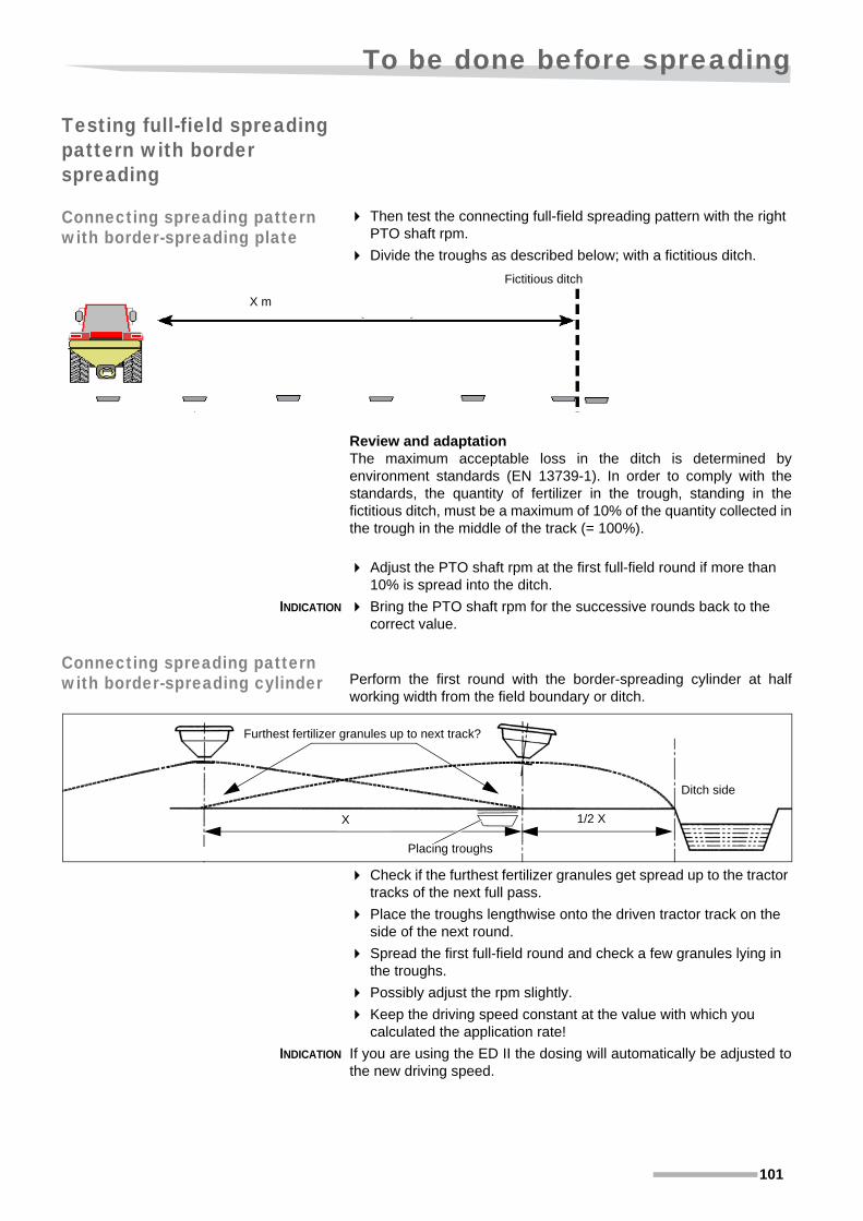
To be done before spreading
101
Testing full-field spreading pattern with border spreading
Connecting spreading pattern with border-spreading plate
Then test the connecting full-field spreading pattern with the right PTO shaft rpm.
Divide the troughs as described below; with a fictitious ditch.
Review and adaptationThe maximum acceptable loss in the ditch is determined byenvironment standards (EN 13739-1). In order to comply with thestandards, the quantity of fertilizer in the trough, standing in thefictitious ditch, must be a maximum of 10% of the quantity collected inthe trough in the middle of the track (= 100%).
Adjust the PTO shaft rpm at the first full-field round if more than 10% is spread into the ditch.
INDICATION Bring the PTO shaft rpm for the successive rounds back to the correct value.
Connecting spreading pattern with border-spreading cylinder Perform the first round with the border-spreading cylinder at half
working width from the field boundary or ditch.
Check if the furthest fertilizer granules get spread up to the tractor tracks of the next full pass.
Place the troughs lengthwise onto the driven tractor track on the side of the next round.
Spread the first full-field round and check a few granules lying in the troughs.
Possibly adjust the rpm slightly.
Keep the driving speed constant at the value with which you calculated the application rate!
INDICATION If you are using the ED II the dosing will automatically be adjusted tothe new driving speed.
Fictitious ditch
X m
Furthest fertilizer granules up to next track?
Placing troughs
Ditch side
1/2 XX

Driving on the road
102
Driving on the road
Before taking the road
Slow moving vehicle signA slow moving vehicle (SMV) sign is a reflective orange triangle witha red border that warns other road users that the vehicle displaying thesign is travelling at 40 km/h (25 mph) or less.
This reflector should then be placed behind your implement if it hidesthe reflector from your tractor.
\ WARNINGObserve the permissible and safe height with regard to
• prescribed maximum height for vehicles in the road traffic regulations,
• high-voltage cables or other cables over the road,
• anticipated maximum headroom.
Pay close attention to these aspects to prevent dangeroussituations that could lead to major material damage and possiblyto serious physical injury.
Before leaving the tractor:
• switch the PTO shaft off,
• release the pressure from the hydraulic system,
• switch the tractor off,
• remove the key from the ignition,
• engage the parking brake of the tractor.
That way you make sure that the tractor cannot be started whenyou are working on the machine and that the machine cannotmove, which could cause severe physical injury.
Before travelling on a public road with your tractor and machine, you should do the following:
Check whether tractor and machine are roadworthy.
check that the lights, warning indicators, protectors and brakes are attached properly and are working.
When the implement obscures the illumination or signsIf the implement, in the transport position, obscures theillumination of any flashing, extremity, tail or stop lamp on thetractor, the implement must be fitted with lighting appropriate totake the place oft he lamp(s) obscured. See your authorizeddealer for an appropriate lighting kit.
Check the run of the quick coupling ropes of the power lift.

Driving on the road
103
Preparing the machine to be transported \ WARNING
Mount lighting and warning signs, if applicable.
Check all folding parts and their locking devices.
• hopper cover,
• border-spreading plate or border-spreading cylinder.
Set all parts of the machine and the tractor, especially the PTO shaft, the hydraulics, the wheels and the electric system, to transport mode.
Check the weight distribution between front and rear axles.
Mount front weights, if necessary.
Check the headroom of the combination.
Lower the power lift, if necessary.
Lock the control lever of the power lift while moving so that the trailed machine is not lowered by accident.
Check if the lights are in good working order.
Check if the dosing unit is closed.
Remove dirt that could fall off while on the road. A dirty road could be hazardous for other drivers.
Control devices, e.g. ropes, hoses, etc. for remote actuation of devices such as cylinders, shall be guided and positioned in a way they never inadvertently release nor block desired movements/actuations!
Always ensure adequate lateral securing of a mounted machine in transport position.
"Check whether the reflector, motor vehicle with limited speed (<25 mph) on your tractor, is hidden by the implement.
"Then fit an additional reflector at the back of the implement.

Use on the land
104
Use on the land
\ WARNINGCaught between moving parts:Be careful not to be caught between moving parts while adjustingthe machine. You could accidentally touch control levers andcause the machine to move.
Only start working once all machine parts have stopped and the control lever have been secured. Wear safety shoes and gloves. Contact with these materials could cause physical injury.
Check the direct surroundingsCheck the immediate environment and keep a constant eye on itat the start, as well as while you are working with the machine.Familiarise yourself with the immediate vicinity. Do not startworking until all people and obstacles within the working area anddanger zone of the tractor and machine have been removed.Never stay or allow anyone to stay within the danger area! If thereare people within the working area and the danger zone it couldlead to injury.
Ensure the tractor is safe when leaving itNever leave the tractor without:
• switching off the PTO shaft,
• switching off the electronic control system,
• lowering all implements to the ground,
• releasing the pressure from the hydraulic system,
• switching off the tractor engine,
• the key must be removed from the ignition,
• engage the parking brake of the tractor.
• Placing all controls in their neutral or park position
Leaving the tractor unsafe could create dangerous situations thatcould lead to injury.
PTO shaft rotates after disengagingAfter switching off the PTO shaft, danger could arise as themachine will continue running because of inertia. Keep a safedistance to the machine until the moving parts have come to acomplete stop. Approaching the machine while it is rotating cancause serious or deadly injuries.
Protecting the environmentSpreading a too high dose of materials outside of the perimeter,especially on water surface, creates a heavy burden on theenvironment. Protect the environment by applying a correctapplication rate in a correct working manner.
Work with a closed cabinFertilizer dust can blow indoors through open windows, doors orother openings. Moreover, the sound level is higher in an opencabin. It is therefore recommended to always work with a closedcabin with active carbon filters in the air inlets. Fertilizer dust anda high sound level can cause physical damage.

Use on the land
105
INDICATION Most types of fertilizer attract water and can thereby form largechunks. These chunks can block the spreader or distort the spreadingpattern.
• When working under moist weather conditions, use a hopper cover that closes well.
• Do not spread without a hopper cover under moist conditions.
• Never leave the fertilizer for a long period of time in the spreader. Chunks can also be formed through moisture in the air.
• Always clean the spreader well after use, including the dosing openings and the spreading spout.
INDICATION Take note of the exact driving distance and make sure there are tramlines.
• If you want to change the application rate or switch to a different fertilizer type (with similar working width and driving speed) you only have to adjust the setting of the regulating rod.
• Always check the set dosing setting with a calibration test
as described in paragraph »Calibration test« on page 91.
Adjusting the machine Before you can make the first pass, you must make adjustments in thefield to:
Spreading height The following is important to ensure that the spreader works properly
• set it to the correct height from the ground or above the crop and
• by levelling it with the lift rod adjustment and top link.
Use the power lift to lift the machine to the correct height.
Measured from the centre of the spreading spout the distance to theground or the crop must be 29 1/2”.
Set the spreader horizontally with the lift rod adjustment and the top link.
Lock the lift limiter in this position.75 cm
(291/2”)
Ground level or the top level of the crops
Rutting of the wheels

Use on the land
106
Last setting check A safety check list is printed below.Do this last check to ensure good spreading results.
Are you working with the correct settings from the correct spreading chart, based on:
• type of fertilizer,
• desired working width,
• desired driving speed?
Did you set the spreader in the correct way?Did you:
• Is the spreading spout height set 29 1/2” above the ground or crop?
• Fine application yes/no?
• is the correct dosing set?
• is the border spreading plate in the transport (or working) setting?
• is the border-spreading cylinder in the correct position?
• Spreading spout angle set correctly?
• Is the spreading spout mounted correctly?
Did you check the following settings:Did you:
• check the dosing setting with a calibration test?
• perform a tray test to check the spreading pattern?
Work in the correct manner:
• Did you set the correct PTO shaft rpm?
• Are you driving at the correct driving speed?
• Did you set the tramlines at the correct distance?
• Wind speed too high?

Use on the land
107
Set driving paths Prevent driving mistakesIt is important that the spreading patterns overlap well to ensure gooddistribution.A deviation in overlap is less serious with average working widths.Especially with large working widths, deviations in overlap can bevisible. This can be prevented by setting tramlines before hand. Youcan do this by marking the tramlines at the headlands with:
• sticks with empty bags,
• picket sticks,
• special display boards.
Visibility of the from point to point on the field is very important. Placeadditional markers in the field if necessary to ensure that the track isclearly visible.
Tramline patterns Your preferred border spreading method determines the tramlinepattern.Select on the basis of the site width, the presence of the sprayertramlines and the spreader's equipment.
Using the border-spreading cylinder with tramlines
Drive half the working width from the border (1/2 X feet) when doingboundary track spreading with border-spreading cylinder (optionalextra).
Set the first way at half the working width (1/2 X feet) from the field edge (in the first sprayer tramline).
The paths that follow are set at the full working width.
See paragraph »Border spreading with the border-spreading cylinder« on page 114.
X m (Xft) 1/2 X m(ft)

Use on the land
108
Using the border-spreading plate with tramlines With one-sided boundary spreading with the border-spreading plate:
• drive the outermost pass approx. 10 feet (1/4 working width) from the field edge.
• the following round at 30 feet (3/4 working width) in the first sprayer tramline.
• the full working width, here 40 feet, with the subsequent rounds.
See paragraph »One-sided boundary spreading with the border spreading plate« on page 111.
At larger working widths, start with the ratio 1/4X and 3/4X.
Carry out the tray test to determine the correct ratios for making the correct connection on the border spreading pattern.
See paragraph »Connecting spreading pattern with border-spreading plate« on page 101.
3 m (10 ft)
12 m (40 ft)12 m (40 ft)
9 m (30 ft)

Use on the land
109
Spreading Once all the preparations have been made you can begin to spread orperform a spreading pattern test. See »Check the spreading pattern (tray test)« on page 94.
Close all the doors and windows in the cabin.
Drive the tractor to the first tramline, depending on the driving pattern required, which may be recognised by the marker in place.
See paragraph »Set driving paths« on page 107.
Engage the PTO shaft and set the correct rpm.
INDICATION Do not allow the PTO shaft to run for longer than is necessary whilethe dosing unit is closed. This will prevent the agitator from grindingthe fertilizer.
Open the dosing units while driving and keep the PTO shaft rpm constant.
Close the dosing units for the turn. The PTO shaft can keep running if you intend to start spreading immediately again.
You will find the correct working method and corresponding distanceson the headland in the next paragraph »Working method on the headland« and
paragraph »Set driving paths« from page 107.
Drive to the next tramline and re-open the dosing units at the right time, as displayed in the next paragraph »Working method on the headland«.
In the event of spreader failure or stoppage:
Stop spreading immediately!
Disengage the PTO shaft immediately!
See then paragraph »Failure and stoppage« on page 116.
INDICATION There can be an increase or a decrease in traction due to different soilconditions. This will affect the driving speed and therefore also theapplication rate in lbs/acre.

Use on the land
110
Working method on the headland
The way you have to stop and turn at the headland depends onwhether you
• do boundary-track spreading from the sprayer tramline with the border-spreading cylinder
• or one-sided boundary spreading with the border-spreading plate.
Do the following when spreading the headland:
Spreading headland when using the border-spreading cylinder
Spread the field edges all around with the border-spreading cylinder.
See paragraph »Border spreading« on page 111.
Stop the spreading by closing the dosing unit of the machine when the tractor’s front wheel reaches the inside headland track.
Do not switch off the PTO shaft.
After turning at a distance of a half to 3/4 working width of a headland track open the dosing units again.
Spreading headland when using the border spreading plate
Spread the field edges as described in the paragraph »One-sided boundary spreading with the border spreading plate« on page 111.
Spread a full-field round in the first sprayer tramline adjacent to the border spreading pattern.
Stop the spreading during the one-sided boundary spreading by closing the dosing units just before you are going to turn.
Do not switch off the PTO shaft.
After turning at a distance of a half to 3/4 working width of a headland track open the dosing units again.
Over and underdosing Depending on soil or crop composition, it is preferable to spread moreor less fertilizer locally. This could for instance be where experiencehas shown that certain parts of the field need more or less fertilizerthan others.
It is possible to over or underdose by
• driving faster whereby the spreading quantity per acre is reduced,
• drive slower, which will increase the spreading volume per acre,
INDICATION The rpm of the tractor engine (therefore also of the PTO shaft) mustremain constant (concerning distributing fertilizer along the width).The driving speed can only be adjusted by selecting another speed!

Use on the land
111
Border spreading Spreading fertilizer up to the border of the property requiresconcentration. On the one hand you want to achieve maximum coverto the field edge to ensure a good crop, while on the other hand youwant to minimise the loss over the field edge.The spreader has 3 different functions and accessories to cater forborder spreading.
• one-sided boundary spreading with the border spreading plate,
• boundary track spreading with the border-spreading cylinder,
• Border spreading with the border-spreading pipe.
When one-sided boundary spreading, drive with the tractor along thefield edge and spread from the border inwards. With boundary trackspreading, drive down the first sprayer tramline from the field edgeand spray in the direction of the border.
Environmental standardsThe maximum acceptable loss over the parcel border is determined byenvironment standards (EN 13739-1). In order to comply with thestandard the quantity of fertilizer spread beyond the parcel bordermust be a maximum of 10% of the quantity distributed in the centrebehind the spreader (= 100%). Test if the border spreading plate(optional extra) door de test therefore always before hand asdescribed in paragraph »Testing the border spreading pattern« on page 98.
One-sided boundary spreading with the border spreading plate
OperationDrive with one-sided boundary spreading at approx. 10 feet from thefield edge. With the aid of the border-spreading plate you complete thefirst full-field spreading pattern that is spread on 40 feet (also the
headland sprayer tramline).
Choice for environment or yield with border spreadingDepending on the set application rate,
• 30% of the full-field application rate (environment setting) or
• 50% of the full-field application rate (yield setting),
you will spread almost nothing or the maximum permissible number ofgranules over the field boundary. see also paragraph »Testing the border spreading pattern« on
page 98.
Setting optionsSet the boundary at the field edge by:
• Placing the border-spreading plate in working position,
• reducing the PTO shaft rpm to 370 rpm,
• reducing the application rate to 30% - or 50% of the full-field application rate
• and, where necessary, changing the turn angle of the spreading spout.
Border spreading plate
Yield
setting 50%
9 m
(30 ft)
3 m
(10 ft)
Environment setting 30%
12 m (40 ft)
First full-field pattern from sprayer tramline

Use on the land
112
Working methodPlacing the border-spreading plate in working position,
Switch the tractor off and remove the keys from the ignition.
Engage the parking brake of the tractor.
Fit the border-spreading plate in working position.
Remove the 2 lock clips that hold the plate in transport position.
Pull the plate forward from its transport position.
Turn the plate to its working position and insert the 2 tubes in the holder pipes.
Secure the plate with the clip through the top pipe on the holder.
Push the other clip back in the transport hook on the hopper.
Check if the position of the border-spreading plate is correct:
Seen in the drive direction the spreading plate stands at an angle
of 20° inward.
Adjusting spreader settingThe spreader is already set at full-field spreading according tothe values in the left column of the chart:
The right-hand column shows the adjustments during borderspreading
NOTE: If you reduce the original application rate to 30 – 50% you can go below the 45 lbs/min. flowrate.
Then go over to fine application.
Holder pipes
Lock clips
Remove 2 lock clips Transport hook
Transport position
Work position
Spreading data Full-field spreading Border spreading plate
Working width (ft)40 drive 10 feet from the
border
Driving speed (mph) 5 5 (higher gear)**
Application rate (lbs/acre) 175 30 or 50% = 58 or 87
Flowrate (lbs/min.) 71 23* or 34*
Adjusting nut position (PK 15.30) 34 Fine application! 34* or 42*
PTO shaft RPM 540 370
Fine application* No Yes (< 45 lbs/min.) *
* With fine application you use the adjusting nut position of a 3x higher flowrate!
** Through lower PTO shaft rpm you must shift one or more gears higher

Use on the land
113
See paragraph »Fine application« on page 84.
In this example the application rate and the flowrate are fineapplication:
• 30% of the full-field application rate 0.3 x 175 = 58 lbs/acre with the flowrate 23 lbs/min.
• 50% of the full-field application rate 0.5 x 175 = 87 lbs/acre with the flowrate 34 lbs/min.
On chart PK 15.30 respectively look for the setting at:
• The setting to be set at 30% is 34.
• The setting to be set at 50% is 42.
INDICATION Maintain the driving speed at the original value!By adjusting the PTO shaft rpm you must engage one or two gearshigher in order to drive at the original speed.
TIP When border spreading with EDII the driving speed is cleared and thenew entered application rate is adjusted automatically to the drivingspeed.
Start the tractor and engage the PTO shaft.
Set the correct PTO shaft rpm: 370 rpm.
Choose such a gear that you drive at the same speed as at the normal PTO shaft rpm.
Drive to the left at 10 feet from the field boundary or ditch.
Spread a round in the field.
In the event of spreader failure or stoppage:
Stop spreading immediately!
Disengage the PTO shaft immediately!
See then paragraph »Failure and stoppage« on page 116.
After border spreading with the border-spreading plate:
Remove the border spreading plate,
and store it in the transport position.
Set the spreader for full-field spreading from the created driving pattern.
see the chart with »Spreading data« on page 112.
Spread a full-field round at full working width from the field boundary, and also on the headland.
See paragraph »Spreading headland when using the border spreading plate« on page 110.

Use on the land
114
Border spreading with the border-spreading cylinder
Operation Drive half the working width from the border (1/2 X Feet) when doingboundary track spreading with border-spreading cylinder (optionalextra). The working width on the side of the field edge can be adjustedby changing the position of the border-spreading cylinder and/or bychanging the PTO shaft rpm. Other settings remain the same as for
full-field spreading.
Choice for environment or yield with border spreadingDepending on the combination:
• Maximum inclination and low rpm (environment setting) or
• cylinder not completely out and higher rpm (yield setting),
you will spread almost nothing or the maximum permissible number ofgranules over the field boundary. see also paragraph »Testing the border spreading pattern« on
page 98.
The maximum acceptable loss over the parcel border is determined byenvironment standards (EN 13739-1). In order to comply with thestandard the quantity of fertilizer spread beyond the parcel bordermust be a maximum of 10% of the quantity distributed in the centrebehind the spreader (= 100%). Test the inclination cylinder thereforealways in advance as described in the paragraph »Testing the border spreading pattern« on page 98.
Setting optionsSet the boundary at the field edge by:
• Setting the inclination of the spreader with the border-spreading cylinder,
• reducing the PTO shaft rpm until the required field boundary is obtained.
Full-field pattern
environment setting
6 m (20 ft)
profit setting
12 m (40 ft)

Use on the land
115
Working method Start the tractor and engage the PTO shaft.
Run the relevant hydraulic control valve for a few seconds to activate the border-spreading cylinder.
Change the inclination of the spreader according to the angle you found during the border-spreading pattern test.
See »Testing the border spreading pattern« on page 98.
Do not change the other settings of the spreader.
Switch the PTO shaft on and set the PTO shaft rpm according to the spreading chart or the value from the border-spreading pattern test.
INDICATION Maintain the driving speed at the original value!By adjusting the PTO shaft rpm you must engage one or two gearshigher in order to drive at the original speed.
Choose, possibly, such a gear that you drive at the same speed as at the normal PTO shaft rpm.
TIP When border spreading with EDII the driving speed is cleared and thenew entered application rate is adjusted automatically to the drivingspeed.
Drive counterclockwise at half working width, here 40: 2 = 20 feet, from the field boundary or ditch.
Spread a round in the field.
In the event of spreader failure or stoppage:
Stop spreading immediately!
Disengage the PTO shaft immediately!
See then paragraph »Failure and stoppage« on page 116.
After border spreading with the border-spreading cylinder:
Set the spreader back to horizontal after completing the border spreading by engaging the relevant hydraulic control valve for a few seconds.
Set the PTO shaft rpm back to standard.
Stopping work
See paragraph »Preparing the machine to be transported« on page 103.
\ WARNINGDirectly after working with the machine and before travelling onthe road, it is important to:
The dosing unit closes. (possibly the valve with the hydraulic operation).
Switch off the pto shaft;
Switch the tractor off and remove the keys from the ignition.
Engage the parking brake of the tractor.
Remove crop rests, dirt and stones from the machine.
Fix the hopper cover.
Take all appropriate measures for road transport.

Use on the land
116
Failure and stoppage
Causes During spreading, if you:
• see that the machine is spreading irregularly or not at all while the dosing unit is open,
• hear a loud noise,
• become aware that the machine is vibrating seriously,
• hear or see that PTO shaft is turning and the safety clutch starts operating,
Stop spreading immediately!Disengage the PTO shaft immediately!
These failures are probably caused by one of the following:
• a hard object blocks the agitator (and stirring device),
• a hard object or a large piece of fertilizer is (partially) blocking the supply of fertilizer due to bridge formation.
• a hard object or a large piece of fertilizer is (partially) blocking the flow of fertilizer through the dosing opening(s),
• crushed and/or damp fertilizer forms an encrusted layer around the stirring device and blocks the flow through the dosing openings,
• damp fertilizer under the dosing plate has formed a lump blocking the flow through the spreading spout. This happens especially when the spreader has not been thoroughly cleaned after it was last used.
INDICATION Most types of fertilizer attract water and can thereby form largechunks. These chunks can block the spreader or distort the spreadingpattern.
• When working under moist conditions, use a hopper cover that closes well.
• Do not spread without hopper cover in damp weather conditions.
\ WARNINGBe careful that nothing gets jammedIt is also easy to get injured while working with the spreader.Work safely with the machine:
• releasing the pressure from the hydraulic system,
• switch the tractor off and remove the key from the ignition,
• engage the parking brake of the tractor,
• wait for all machine parts to come to a standstill before you approach it,
• wear protective clothing, such as safety gloves and shoes,
• carefully follow the instructions given.
Friction with these materials could cause physical injury.
Avoid contact with the fertilizer and other materialWhile working with the spreader, you might come into contact withfertilizer or other substances that you want to spread. Wearprotective clothing and gloves, read the safety instructionsprovided by the supplier and follow their directions. Contact withthese materials could cause physical harm.

Use on the land
117
• Never leave the fertilizer for a long period of time in the spreader. Chunks can also be formed through moisture in the air.
• Always clean the spreader well after use, including the dosing openings and the spreading spout.
Working method
To find the cause of the failure or stoppage and solve it as far aspossible, proceed as follows.
Disengage the PTO shaft immediately!
Switch the tractor off, remove the key from the ignition and engage the hand brake of the tractor.
Examine the spreading spout and the discharge opening to see what the cause of the failure/stoppage is.
If necessary, disassemble the spreading spout for better accessi-bility.
Pass an object such as a screwdriver through the discharge opening and carefully feel if you can find an object in or damage to the dosing openings.
Damage If you see damage to the spreading bracket, then the failure is mostlikely caused by a hard object. The spreading spout is probablydamaged too. You must first repair the damage or have it repairedbefore continuing with spreading.
Start the tractor and close the dosing unit.
Take all appropriate measures for road transport.
See paragraph »Preparing the machine to be transported« on page 103.
On the site of a lockable storage depot:
Empty the hopper.
Remove the object that caused the damage.
Repair the machine or have your dealer do it.
Also check the safety clutch setting as described
in paragraph »Setting the safety clutch« on page 62.
\ WARNINGHandle with careCautiously approach the machine and handle with care. Therecould be hot or live parts! Contact with these materials couldcause physical injury.

Use on the land
118
Stoppage If you have not found any damage, the failure is probably due tostoppage from an encrusted layer of fertilizer.
Try to reduce the size of the lump or encrusted layer with an object such as a stick or screwdriver.
INDICATION In case you have to disassemble the sieve from the top to reduce thelump or encrusted layer, you need to refit it immediately.
If you can reduce the lump or encrusted layer in this way:
Inspect the hopper contents for other lumps and reduce them.
Close the hopper cover.
Continue spreading.
If you have not managed to reduce the lump or encrusted layerbecause it is out of reach or there is no tool at your disposal:
Close the hopper cover.
Follow the working method as described in the previous paragraph »Damage« until emptying the hopper.
Remove or reduce the lump or encrusted layer.
If necessary, dry the hopper and the dosing mechanism.
Fit the sieve.
Refill the spreader.
Check the fertilizer for lumps before and after filling.
Apply the hopper cover.

Storing the machine
119
Storing the machine
Cleaning If the machine is being put away for a short or longer period of time itis recommended that you lubricate and clean it first. If it is lubricatedfirst you will prevent dirt, fertilizer and water from entering thebearings.The advantages of this method of working are:
• additional checks on the machine right after work,
• ensuring the longevity of the machine,
• less delays due to problems while working with the machine.
Lower the spreader.
Open the dosing unit.
Switch the tractor off, remove the key from the ignition and engage
\ WARNINGAvoid contact with the fertilizer and other materialIt is easy to come into contact with the materials when puttingaway the machine. Always wear protective clothing, such assafety gloves, shoes and goggles. Read and adhere to theadditional safety instructions and the of the material producer.Contact with the materials could lead to injury. Contact yourphysician in such an event!
Be careful that nothing gets jammedIt is also easy to get injured while working with the spreader.Work safely with the machine:
• switch the tractor off and remove the key from the ignition,
• engage the parking brake of the tractor,
• wait for all machine parts to come to a standstill before you approach it,
• wear protective clothing, such as safety gloves and shoes,
• carefully follow the instructions given.
Friction with these materials could cause physical injury.
Protect the machineFertilizer and other salts have a great influence on the rate ofcorrosion. Empty the hopper at the end of activities. Protect themachine by always cleaning it after using such material and patchbreaks in the paint. Corrosion affects the strength of theconstruction and the operation of the machine, which could leadto a shortened life span.
Be careful while cleaning with high pressure cleanersThe machine can be cleaned with water or steam. Use lowpressure with turning parts, sensors, parts of the electric system,hydraulic hoses and plastic parts.
Waste storage and disposalThe waste water from cleaning the machine is contaminated withfertilizer and possibly also with lubrications. Collect the waste anddispose of it in accordance with your regional requirements.

Storing the machine
120
the parking brake of the tractor.
Clean old grease from the grease nipples with a cloth.
Lubricate the machine grease nipples.
See paragraph »Maintenance« on page 122.
Clean the machine.
TIP When using a high-pressure cleaner, do not aim it at the seals. Thatway you will prevent dirt and moisture from entering.
Give each grease nipple a bit of grease after hosing off.
Disconnecting the machine
Proceed as follows to store the machine in stable condition for ashorter or longer period.
switch off the pto shaft;
Check if the tap in the hydraulic hose is closed.
Take the pressure off the hydraulic system.
Switch the tractor off and remove the keys from the ignition.
Engage the parking brake of the tractor.
Adjust the length of the top link in such a way that it is no longer live.
Release the top link by undoing the release rope from the catch hooks and pulling the top link up.
Release the lower links by undoing the release ropes from the catch hooks and lowering the power lift as far as possible.
\ WARNINGDisconnect safelyYou may only disconnect the machine when:
• all parts are in a safe condition,
• your immediate surroundings are safe,
the hopper is empty.
Work carefully:
• check the environment (children!) and ensure that nobody is in the vicinity of the tractor or the machine.
• wear safety gloves and shoes,
• the machine or parking support must only be placed on a straight, firm surface,
• never stand between the tractor and machine while the power lift is operated externally while disconnecting the machine. Using the power lift entails the risk of accidents by crushing or jack-knifing,
• operate the power lift slowly and carefully,
• the power lift during disconnection must be placed in such a position that accidental release or lowering would be eliminated,
• sufficient distance must be maintained between parts that rest on the ground.
Working unsafe could cause serious injuries.

Storing the machine
121
TIP If you cannot lower the power lift far enough to release the catchhooks, we advise you to place the spreader on a firm, stable ramp, forexample a pawl.
TIP For the VS600 model, it is easy to disconnect and put away the emptyspreader with a set of parking wheels.
Drive the tractor about 3/4 foot forward (maximum distance depends on the range of the coupling shaft; the halves must always overlap each other).
Switch the tractor off, remove the key from the ignition and engage the parking brake of the tractor.
Disconnect the electric plugs and hang them in the container.
Disconnect the hydraulic hoses.
Place the protective caps on the hydraulic hose connections.
Hang the hydraulic hoses in the hose coupling support.
Disconnect the coupling shaft and hook it up.
Preparation for winter storage
At the end of the season the machine must be prepared for winterstorage.
If the machine is being put away for a short or longer period of time itis recommended that you lubricate and clean it first. If it is lubricatedfirst you will prevent dirt, fertilizer and water from entering thebearings.The advantages of this method of working are:
• additional checks on the machine right after work,
• Ensuring the longevity of the machine,
• less delays due to problems while working with the machine.
TIP When using a high-pressure cleaner, do not aim it at the seals. Thatway you will prevent dirt and moisture from entering.
Clean the machine.
Let the machine dry.
Paint any damaged paintwork.
Lubricate and oil all points once again to ensure conservation.
See paragraph »Maintenance intervals« on page 124.
Coat blank parts such as piston rods of hydraulic cylinders with preserving grease.
TIP Only use grease that would not harden or dry. That will preventdamage to cylinder oil seals.
TIP The red colour of the polyester hopper of your Kubota VS is sensitiveto UV radiation from sunlight. Discolouration of the hopper may occur.We therefore advise to store your machine out of direct sunlight whennot in use.
Store the ED II control box in a place where it cannot be damaged and is not exposed to temperatures below -20°C.
Parking wheels

Maintenance
122
Maintenance
\ WARNINGRepair damage safely and without delayRepair the machine safely before you continue with work:
• place the tractor and machine on a firm, straight surface,
• disengage the PTO shaft,
• releasing the pressure from the hydraulic system,
• switch the tractor off and remove the key from the ignition,
• engage the parking brake of the tractor,
• wait until all parts have stopped moving. The mass (inertia) could keep the machine running for a bit!
• wear protective clothing, such as safety gloves and shoes,
• carefully follow the instructions given,
• use the correct tools,
• bigger or heavier parts must be locked and secured to lifting gear when being replaced,
• parts that could move unintentionally must be supported and secured,
• do not climb on parts of the machine that are not in use. Only use stepladders, ladders or other tools intended for this purpose.
• disconnect the feed while working on the electric system.
• disconnect the cables from the battery and the dynamo before arc welding on the tractor or the connected machine!
Performed by an authorized personAlways have an authorized expert perform maintenance andrepairs, as described in paragraph »Authorization« on page 12. All forms of responsibility of the manufacturer become null andvoid and the guarantee lapses if maintenance and repair work areperformed by unauthorized persons.
Do not modify the machineDo not modify the machine in any way. Unauthorized modifica-tions may impair the function and/or safety and affect the life of themachine.
Only use original parts when replacingUsing other non-genuine parts could lead to problems and unsafesituations when using the machine.

Maintenance
123
Adhere to all the safety precautions as described in paragraph »Safety regulations« from page 11.
\ WARNINGAccessories and parts must be correctly mountedAssemble accessories and parts according to specifications andattach them only for their designated purpose; ensure that it islocked correctly. Accessories and parts which are not fastenedsecurely could lead to personal injury and damage to the crop andmachine.
Tighten all bolts and nutsCheck that all the nuts and bolts are well set. Check this againafter one hour of use
• after delivery and
• carrying out maintenance or repair activities.
Avoid contact with materialsYou should only come into contact with the materials whencleaning the machine. Always wear protective clothing, such assafety gloves, shoes and goggles. Read and adhere to theadditional safety instructions and the of the material producer.Contact with the materials could lead to injury. Contact yourphysician in such an event!
Explosion danger because of nitrateFertilizers that contain nitrate can create an explosion danger if theycome into contact with fire. All fertilizer remnants should thereforebe removed from voids, corners, tubes and tubing before welding,cutting or grinding on the machine.

Maintenance
124
Maintenance intervals
da
ily
aft
er t
he
firs
t 1
0 h
ou
rs
wee
kly
eve
ry 1
00
ho
urs
min
. 1
x p
er
yea
r
As
rec
om
men
ded
If w
orn
Pa
ge
Inspection
»Checking bolts and nuts« • • 129
»Checking the hydraulic system« • • 130
»Agitator and stirring device« • • 134
»Spreading spout check« • • 135
»Control of the pendulum mechanism« • • 133
»Protective covers« • • • 134
coupling shaft • • 62
Lubrication
»Coupling shaft« • 125
»Spreading unit« • 126
»Manual or hydraulic operation pin joint« • 126
ED II actuator •Add oil
»Tractor side quick lock« of the coupling shaft • • 125
»Dosing baffle« • 128
Replace
Hydraulic hoses and connectors • • 130
Spreading bracket • 135
stirring device • 134
Spreading spout • • 135
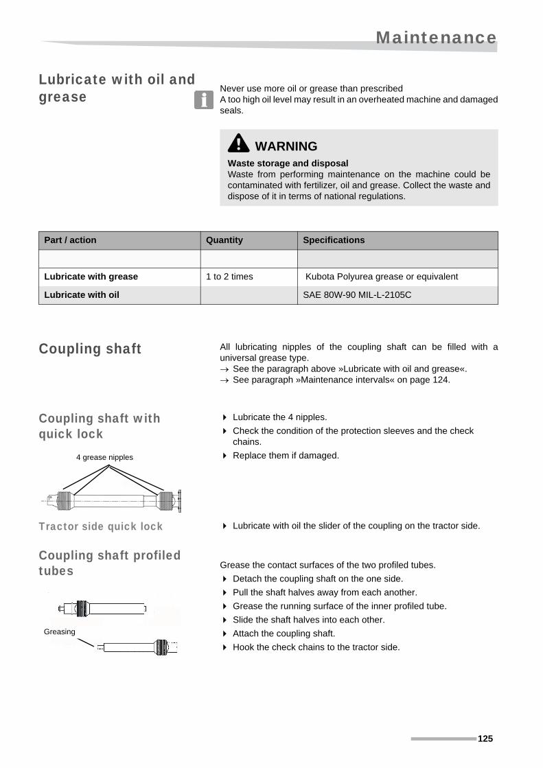
Maintenance
125
Lubricate with oil and grease Never use more oil or grease than prescribed
A too high oil level may result in an overheated machine and damagedseals.
Coupling shaft All lubricating nipples of the coupling shaft can be filled with auniversal grease type. See the paragraph above »Lubricate with oil and grease«. See paragraph »Maintenance intervals« on page 124.
Coupling shaft with quick lock
Lubricate the 4 nipples.
Check the condition of the protection sleeves and the check chains.
Replace them if damaged.
Tractor side quick lock Lubricate with oil the slider of the coupling on the tractor side.
Coupling shaft profiled tubes Grease the contact surfaces of the two profiled tubes.
Detach the coupling shaft on the one side.
Pull the shaft halves away from each another.
Grease the running surface of the inner profiled tube.
Slide the shaft halves into each other.
Attach the coupling shaft.
Hook the check chains to the tractor side.
\ WARNINGWaste storage and disposalWaste from performing maintenance on the machine could becontaminated with fertilizer, oil and grease. Collect the waste anddispose of it in terms of national regulations.
Part / action Quantity Specifications
Lubricate with grease 1 to 2 times Kubota Polyurea grease or equivalent
Lubricate with oil SAE 80W-90 MIL-L-2105C
4 grease nipples
Greasing

Maintenance
126
Manual or hydraulic operation pin joint
The operation of the dosing has, manually and hydraulically operated,an articulating arm which opens the dosing through the regulating rod.
The hinge point must be lubricated daily
VS 220/330
Lubricate the pin joints of the VS220/330 with oil.
VS400-1000
Grease the nipple on the hinge bushing of the VS400/500 (VITI) and VS600 -1000 manual or hydraulic operation.
Spreading unitThe spreading unit has 5 grease nipples:
Lubricate them daily.
See the following paragraph on page 127 on how to reach the grease nipples.
Lubricate the pin joints of the VS220-330 manual operation with oil
Grease nipple on the hinge bushing for operation with VS400-1000
5 grease nipples spreading unit

Maintenance
127
Angle setting bearing You will find the angle setting behind the cap in the protective cover ofthe spreading unit.
Remove the cap in the protective cover
Turn the flywheel manually until the angle setting is in front of the hole.
Flywheel bearings The grease nipple on the flywheel bearing housing can also bereached through the hole in the protective cover in front of the anglesetting piece.
Grease the grease nipple on the flywheel bearing housing.
Work in safety!
Close the hole in the protective cover off again with the cap
Grease nipple on the angle setting
Grease nipple on the flywheel bearing housing
Put the cap back into the hole of the protective cover

Maintenance
128
Pendulum axis and fork bearings On the spreading spout side of the spreading unit there are:
• 2 grease nipples on the fork bearing housings; left and right next to the spreading spout mounting flange.
• and 1 grease nipple on the bearing housing of the central pendulum axis
Dosing baffle The dosing openings are opened and closed through a dosing platesituated below that rotates.
Grease the plate after every cleaning:
Close the dosing
Apply the oil to the dosing plate through the 3 holes in the spreading plate.
subsequently open and close the dosing repeatedly.
The oil is distributed over the plate surface.
Grease nipples on fork bearing housing (left & right)
Grease nipple on the pendulum axis bearing housin
Dosing plate closed
Spreading plate with 3 holes

Maintenance
129
Torques Guidelines for torques (in ft.lbs) for self-locking nuts, hexagon boltsand nuts..
* The friction coefficient of 0.10 applies to oiled sheets, cast iron,hardened surfaces, greased threads, etc. The higher value of 0.13applies to dry sheets.
Torques for bolts and nuts with serrated lower edges 10% extra, suchas:
• Tensilock (K100)
• Whizlock.
Exceptions to this table are listed in the parts and/or instructionmanual.
Checking bolts and nuts
Check all bolt and nut connections:
Turn all nut and bolt connections up to the point as given in the chart below:
• after the first operating hour.
• regularly (at least once a week).
Torques
Quality 4.6 8.8 10.9 12.9
Friction* 0.10 0.13 0.10 0.13 0.10 0.13 0.10 0.13
Thread
M5 1.3 1.5 3.7 4.4 5.2 5.9 6.6 7.4
M6 2.2 3.0 6.6 7.4 9.6 11.1 11.1 13.3
M8 5.9 6.6 15.5 18.5 22.9 26.6 26.6 31
M10 11.8 14.0 29.5 36.9 44.3 51.7 51.7 62.7
M12 19.9 23.6 51.7 62.7 77.5 88.6 88.6 107.0
M14 31.0 36.9 84.9 99.6 121.8 143.9 143.9 169.7
M16 48.0 56.1 129.2 155.0 191.9 221.4 221.4 258.3
M18 66.4 81.2 184.5 214.0 258.3 310.0 302.6 361.6
M20 92.3 110.7 258.3 310.0 369.0 442.8 428.0 516.6
M22 125.5 147.6 346.9 413.3 494.5 590.4 575.6 686.3
M24 155.0 184.5 442.8 524.0 634.7 752.8 738.0 870.8
\ WARNINGNuts and bolts could become loose through vibrations. Check the nuts and bolts regularly to prevent damage to themachine and possible injury, especially after maintenance.

Maintenance
130
Checking the hydraulic system \ WARNING
Hydraulic oil is under high pressureNever try to stop a leak with your fingers. Never try to locate ahydraulic leak or try to contain it by hand! When inspecting alwaysuse appropriate aid (e.g. a piece of wood or sheet metal) and wearsafety goggles, safety gloves and gloves! High pressure fluideasily penetrates skin and clothes, causing severe injuries. In theevent of injury, contact your physician immediately!
Keep your distance from the hydraulics during inspecting and test running
Use a stick to bend the hydraulic hoses when checking them for leakage.
That way you will keep at sufficient distance.Oil jets or hoses that snap back may cause serious physical injurydue to the prevailing pressure and temperature.
Work safely on the hydraulic systemThe hydraulic system could be under high pressure. Do not workon the hydraulic system without:
• releasing the pressure from the hydraulic system,
• switching off the electric control system,
• switching the tractor off,
• the key must be removed from the ignition,
• engage the parking brake of the tractor,
• using the proper tools,
• wear safety glasses, gloves and shoes.
Working in an unsafe manner on the hydraulic system could leadto injury and damage to the machine. In the event of injury, contactyour physician immediately! There is also the risk of infection!
Before operating the hydraulic system, check all connections andhoses for damage and leakage.
\ CAUTIONDo not exceed the maximum hydraulic pressure of 210 bars/3045 psiPrevent the pressure in the hydraulic system from exceeding 210bars/3045 psi! Working above the permitted pressure maydamage your machine and result in dangerous situations.
CAUTION
MAXIMUM HYDRAULIC PRESSURE• THE TRACTOR’S HYDRAULIC
PRESSURE MUST NOTEXCEED 210 BAR (3045 PSI).
TO AVOID MACHINE DAMAGE AND INJURY:CHECK THE HYDRAULIC PRESSURE
max210 bar

Maintenance
131
Replacement intervals
\ WARNINGRegularly inspect the hydraulic system(hoses, pipes, connections). All hoses, piping and connectingpoints must be checked regularly, but at least once a year, by anexpert for leakages or visible damage!
The lifetime of a hose should be 6 years maximum (see the production date on the hoses).Damaged or old parts must be replaced with new ones that complywith the technical specifications of the manufacturer of themachine.Damage to the hydraulic system could lead to injury.

Maintenance
132
Inspection criteria It is not permitted to carry out repairs on hydraulic hoses!Replace hoses if the following is detected during inspection:
• damage to the exterior up to the armouring (such as abrasion marks, cuts and tears),
• the exterior becoming brittle (tears in the hose),
• deformation which is not in accordance with the natural shape of the hose,
• both in de-pressurized and in pressurized state
• or with bends, for example detaching layers,
• blister formation,
• leakages,
• not mounted as per requirements,
• hose coming out of the connectors,
• corrosion of the connector reduces the working and strength,
• exceeding the storage and the operating limits.
Only use original parts when replacing hoses.
Hoses must be placed and mounted in the proper way.
Be careful not to change the connections.
• Replaced hoses must be suitable to the permitted work pressure and be resistant to chemical, mechanical and thermal loads.
Replacing Run the hydraulic control valves until all the cylinders are engaged.
Take the pressure off the hydraulic system.
Switch the tractor off and remove the key from the ignition and engage the parking brake of the tractor.
Disengage the machine,
See paragraph »Disconnecting the machine« on page 120.
Demount the connectors with the proper tools.
Collect the oil that drips from the cylinders and the hoses.
Mount new hoses and put them so that they would not get pinched.
Dispose of the collected oil as required by national legislation.
Operate the hydraulic control valves of the tractor very carefully at first after replacing the hoses
as there could still be pockets of air in the pipes! Open and closeall the hydraulic control valves a few times before you startworking.

Maintenance
133
Control of the pendulum mechanism
Spreading spout angle adjustment
Check the angle adjustment for correct working and setting.
Remove the protective cap from the hole of the angle adjustment.
With the key turn the adjustment to min. and back.
See paragraph »Spreading spout angle adjustment (accessory)« on page 87.
Check the condition of the angle setting piece and the bearing for play and free rotation.
Possibly disassemble the adjustment as a check.
This can possibly be done without disassembling the unit cover.
Turn the two bolts out of the turn adjustment cap.
Remove the cap, the plastic adjustment and the spring.
Check the free rotation and the fit of the aluminium setting piece.
Mount the whole with the notch in the aluminium set piece pointing to the top (max.).
NOTE The plastic adjustment also has an arrow that must point to the anglein the setting piece and max. on the cap during the assembly. See the top photo.
\ WARNINGAvoid contact with the fertilizer and other materialYou will most likely get into contact with the fertilizer and othermaterial you may wish to spread while filling, adjusting and testingthe spreader. Wear protective clothing and safety gloves, read thesafety instructions provided by the supplier and follow theirdirections. Contact with these materials could cause physicalharm.
Be careful that nothing gets jammedIt is easy for parts to get jammed while adjusting and checking thespreader. Work safely while checking and adjusting:
• switch the tractor off and remove the key from the ignition,
• engage the parking brake of the tractor,
• wait for all machine parts to come to a standstill before you start with the adjustments,
• wear protective clothing, such as safety gloves and shoes,
• carefully follow the instructions given.
Friction with these materials could cause physical injury.
Arrow on the plastic turn adjustment
Arrow on the key
Angle in setting piece

Maintenance
134
Other bearings
Check the bearing of the flywheel,
Fork and pendulum axle for play.
Other check points Protective covers
Check the protective covers of spreading unit and PTO shaft.
Replace damaged protection immediately!
Agitator and stirring device
Check the condition of the agitator (and the stirring device)
• Check the points of the agitator and stirring device for breakage and wear and tear.
• Check agitator lock clip for correct assembly.
Replace worn-out parts immediately!
These parts determine the good working order of your machine.
Flywheel bearings
Bearings of the pendulum axle
Fork bearing
Protective cover spreading unit
Protective cover coupling shaft
stirring device en lock clip
Agitator

Maintenance
135
Spreading spout check Check the condition of the spreading spout for:
• Damage, wear and tear or cracks in the spout and spreading bracket.
• State of the steel linings in the left and right discharge opening.
• Presence of the plate in the middle of the pipe mouth.
Replace the spreading bracket or the entire spreading spout in the case of severe wear and tear or the lack of the said parts.
NOTE! Replace the parts on time!The spreading result is highly dependent on the state of the spreadingspout and spreading unit.
Spreading bracket
Plate in pipe mouth Steel lining in discharge opening

Accessories
136
Accessories
General The following accessories are available for your machine in order toadapt it to your tractor and/or working conditions. see also the accessory pages of the spare parts manual.
All of the responsibilities of the manufacturer lapse and the guaranteebecomes null and void if non-genuine parts are used.
Hydraulic operation In the case of hydraulic operation the dosing mechanism can beoperated with a single-acting hydraulic valve from the tractor. Thetractor cabin may remain closed, with the advantage of:
• lower noise level,
• no granules, seeds, powders, etc. in the cabin,
• dust from spread products cannot blow inside.
PS-ED II electronic dosing system
The PS-ED II is an electronic remote control that also adjusts thedosing to the driven speed.You work with:
• correct application rate by adjusting to your driving speed,
• simple processing of your calibration test,
• acre counter and measurement of the way covered,
• a closed cabin.
Calibration container A calibration test is essential to obtain accurate settings for theapplication rate. The calibration container is an indispensable tool forthis. The spreading spout can remain mounted. See paragraph »Calibration test« on page 91.
Hydraulic operation
Actuator sends the dosing
PS-ED II control box

Accessories
137
Border-spreading cylinder
The border-spreading cylinder is a simple solution to obtainreasonable border spreading. This solution is simple to set andrequires minimum effort.The border-spreading cylinder also functions as extension set in shortlower links of the power lift of your tractor. See paragraph »Border spreading with the border-spreading
cylinder« on page 114.
Border spreading plate With the border-spreading plate you can carry out one-sided boundaryspreading. See paragraph »One-sided boundary spreading with the border
spreading plate« on page 111.
Fine application set Spreading of small application ratesWith a low application rate and/or low driving speed the 3 dosingopenings are only slightly open. Blockages and dosing of insufficientaccuracy can be the result.We therefore advise that you make use of the fine application kit if theflowrate is less than 45 lbs/min. If the 2 dosing openings are closedoff and the opening in use consequently will be wider opened.
Border-spreading cylinder
Border spreading plate
Fine application plate
Dosing openings closed off

Accessories
138
Spreading spout angle adjustment
Working widths vary with the angle of the spreading spoutThe back and forth turn of the spreading spout can be set to a smallerangle with an optional key.This enables you to reduce the working width by approx. 25%.The standard spreading spout spreads with the small angle of approx.30 feet working width instead of 40 feet with the larger angle.
Spreading spouts for miscellaneous activities
Various spreading spouts are available for other applications for fruitfarming, fish farms, road construction and gritting.
Short spreading spoutSmaller working width with the maximum turn angle of the pendulumcan be spread with the short spreading spout. This spreading spout issuitable for spreading work where the turn angle for the fertilizer usedmust stay as large as possible to effect good agitator working.
Wide row fertilisation pipeOrchard spreading with greater distance between the rows of trees.
Narrow strip fertilisation pipeFertilising or spreading of herbicides between very small planted stripsat 3’ to 4’ row distance.
Spreading spout angle adjustment
Key
Angle min. 48oAngle max. 56o
Short spreading spout
Spreading pattern
For working width 13’-26’
Row fertilising pipe
Spreading pattern
Orchard spreading with working width 6.5’-26’
Strip fertilisation pipe
Spreading pattern
Fertilising rows with 3’-4’ working width

Accessories
139
Wide salt and grit-spreading pipeFor sand, salt and grit-spreading for winter maintenance and roadconstruction.
Narrow salt and grit-spreading pipeFor sand, salt and grit-spreading in winter maintenance and roadconstruction on narrow roads and paths.
Narrow spreading spoutSpreading on very small working widths on tramlines in orchards andgreenbelts.
Border-spreading pipeThe alternative to the border-spreading plate is one-sided boundaryspreading with the border-spreading pipe. Driving clockwise the lastfull-field pass is completed.
Salt and grit-spreading pipeGritting and road construction, working width 16’-19’
Spreading pattern
Salt and grit-spreading pipeGritting and road construction working width 6.5’-13’
Spreading pattern
Narrow spreading spout
Spreading pattern
Orchard and green belt spreading on working width 5’-10’
Border-spreading
Spreading pattern
One-sided boundary spreading

Accessories
140
A-symmetric spreading spout (right)For proper release of fish nutrition for breeding ponds and dike fertili-sation
Hopper extensions The loading volume of the spreader can be increased by fitting ahopper extension. See paragraph »Technical specifications« on page 33.
Keep the increase in the filling height and the weight of the machineinto account. see paragraph »Calculate the axle load with tractor-mounted
machines« on page 15,
Hopper cover The hopper cover protects the fertilizer in the hopper against humidityand dirt.
Lights If you are transporting on a public road there are lights available inorder to comply with legal requirements. See paragraph »Driving on the road« on page 102.
Spreading pattern
A-symmetric pipe (right)
Fish ponds and dike spreading at a working width of 12’- 20’
Hopper extension
Hopper cover
\ WARNINGIf the implement, in the transport position, obscures the effectiveillumination of any flashing, extremity, tail or stop lamp on thetractor, the implement must be fitted with lighting appropriate totake the place of the lamp(s) obscured. See your authorizeddealer for an appropriate lighting kit.

Accessories
141
Slow moving vehicle signA slow moving vehicle (SMV) sign is a reflective orange triangle witha red border that warns other road users that the vehicle displaying thesign is travelling at 40 km/h (25 mph) or less.
This reflector should then be placed behind your implement if it hidesthe reflector from your tractor.
Parking wheels set In order to put away the machine safely by one person, a parkingwheels set is available.
Parking wheels

Trouble shooting
142
Trouble shooting
Troubleshooting table
Problem Possible cause Solution Page
Incorrect application rates (lbs/acre)
Dosing setting incorrectly setSet the dosing setting as per the instruc-tions
76
Dosing setting not checked with a calibration test
Do a calibration test 91
Incorrect setting for fine dosageSet the dosing setting for fine application as per the instructions
84
Driving speed too high or too lowAdjust the driving speed or the application rate
76
Incorrect distance between the driving tracks
Always set the driving tracks before spreading
107
New type of fertilizer spread with the same settings as the previous type. Quality varies greatly between types.
Determine the characteristics of the fertilizer, look for the relevant spreading chart and set the spreader again
75
74
The flow of the fertilizer is blockedClean the machine well after each use. Replace the agitator if it is worn out
119
Average quality fertilizer (too soft, broken, mixed types) or incorrect storage
Contact your supplier. Update the storage area. Spread with smaller widths as far as possible
76
Great amounts of dust while spreading
PTO shaft rpm too high Check the PTO shaft rpm 76
Stirrer grinds. Dosing closed for too long with the PTO shaft running
Switch the PTO shaft off after closing the dosing. Check the stirrer for damage
Average quality fertilizer. 80% of the granules with a diameter between 2- and 4,7mm (80 - 190 Thou.)
Determine the distribution and spread with small working widths if possible
76

Trouble shooting
143
Spreading tracks visible among the crops
Blend of fertilizer types used. A blend can become unmixed again or types of fertilizer could contain varying spreading qualities.
Check the type, pattern and distribution. Spread with smaller widths as far as possible
79, 76
New type of fertilizer spread with the same settings as the previous type. Quality varies greatly between types.
Determine the characteristics of the fertilizer, look for the relevant spreading chart and set the spreader again
75
74
Use of wrong spreading chartDetermine the characteristics of the fertilizer and select the correct spreading chart
75, 75
Working with unfavourable weather conditions: high levels of humidity, rain, heat or high wind speeds (> 16’ /sec)
Only work under good weather conditions
Incorrect overlapping of the spreading pattern
Always set the driving tracks before spreading
107
Horizontal/vertical settings of the machine not correct
Check if the machine is standing level horizontally and vertically, unless the spreading chart indicates otherwise
70
Spreader not set to the correct heightCheck and set to the correct working height (29.5” above the crops or soil) and inclination
70
Working width incorrectCheck the settings on the spreading chart or website and the PTO shaft rpm
75,71
Worn or incomplete spreading spout Check the spreading spout 135
Tire pressure on the left and right not the same
Check the tire pressure
Reduced rpm of the spreading mechanism through the loss at the safety clutch
Make sure that the spreading mechanism is running smoothly. Check the safety clutch
133,62
Powerful vibrations perceptible
Shut down the PTO shaft immediately! Attend to the problem to prevent damage
Stoppage due to hard object Remove the object
Bridge formation due to wet fertilizerBreak the growth or replace the fertilizer altogether
PTO shaft working angle out of working reach
Limit the working angle to a maximum of 30º
63
Problem Possible cause Solution Page

Falling into disuse
144
Falling into disuse When the life span of the machine has finished, its separate partsmust be properly disposed of. Keep local legislations in mind with this!
Metal partsYou should dispose at requirements all metal parts appropriately.
Plastic partsAll plastic parts can be disposed of as unwanted garbage.
Oilthe hydraulic oil must be disposed of at a used-oil recycling company.
RubberRubber parts such as tires and hoses should be disposed of properly.
Electronic wasteElectronic waste, such as the electronic control box and the machineboxes must be disposed of at specialist companies.
fertilizerRemaining fertilizer must be stored or disposed of in accordance withthe regulations for chemicals.

Liability
145
Liability
Liability Without prejudice to the other terms of these General Conditions, theseller is only responsible for damage caused by breach of the expresswarranty:
the buyer is completely responsible for damage that result from grossneglect due to the buyers own actions or due to gross negligence ofthe buyers legal representatives or supervising employees.

Liability
146
Complaints regarding product completeness
The following conditions apply, along with the express limitedwarranty:
• The buyer must check the equipment, accessories and spare parts upon delivery for transport damage and completeness. Any possible shortcomings must be reported without delay.
• The seller will only consider complaints if the buyer reports such in writing within fourteen days after delivery by the seller.
• The buyer must report hidden damage as soon as it becomes evident, but no later than six months after delivery of the equipment.
Guarantee You can obtain the applicable express limited warranty for yourmachine from your dealer.

EGC declaration of conformity
147
EGC declaration of conformity
In accordance with EU Directive 2006/42/EC
WeKverneland Group Nieuw-Vennep BVHoofdweg 1278NL-2153 LR Nieuw-VennepThe Netherlands
declare fully under own responsibility that the product
to which this declaration refers, complies with the basic safety andhealth requirements under the EU Directive, 2006/42/EEC.
For the relevant implementation of the safety and health requirementsmentioned in the EU directive, the following standards must be takeninto account:
• EN ISO 12100 :2010
• EN ISO 4254-1 :2013
• EN ISO 4254-8 :2009
• EN13739-2 :2011*
Kverneland Group Nieuw-Vennep BV Nieuw-Vennep, 21.09.2015
M. SvendsenManaging Director
* The fertilizer spreader equipped with a calibration container and border-spreading plate.
Type plate VS 400 / VS400VITI
Type plate VS 600
Type plate VS 220/330
VS220 / VS400 / VS400VITI / VS600 and accessories
Serial number VN223 / VN224 / VN225 / VN226

Notes
148
Notes

Index
149
Index
AAccessories
border spreading plate 137Calibration container 136hopper cover 140Hopper extensions 140hydraulic operation 136lights 140tramline cylinder 137
adjust the safety clutch 62adjusting
Application rate 73correct details 75different driving speed 82Dosing setting 73Fine application 84machine 70spreader 80spreading height 105
Application rate 30adjusting 73inspection 91
applications of the machine 26axle load 15
Bborder spreading
border spreading plate 111tramline cylinder 114
border spreading plate 137headland 110one-sided boundary spreading 111spreading pattern 28Spreading the headland 110tramlines 108
boundary track spreadingspreading pattern 29tramline cylinder 111, 114
Ccalculating the axle load 15Calibration container 136
Mounting instructions 58calibration test
adjusting the dosing setting 93adjusting the dosing setting with fine application 85Testing the dosing 92
checkbolts and nuts 129calibration test 91Delivered machine 35
field adjustment 106hydraulic system 68spreading pattern 94
checking the hydraulic system 68Clean 136complaints 146connecting
electric plugs 68hydraulic hoses 68power lift 69
Connectors 129maintenance 129
control systemsafety 21
coupling 61coupling shaft
checking length 61fitting 61maintenance 125profiled tubes 125safety 20safety clutch 62
Ddata
technical 33declaration of conformity 147Discharge point
transverse distribution 31Disconnect
Winter storage 121Dosing
Deviating application rates 82different driving speed 82testing 92
dosing mechanismadjusting 133check 133
Dosing settingadjusting 73correct 93Deviating application rates 82different driving speed 82testing 92
driving speedadjusting the dosing setting 82
EEC declaration 147electric plugs
connecting 68environment 26, 35environmental standards 26

Index
150
Ffailure 116
causes 116working method 117
failures 142trouble shooting 142
Falling into disuse 144fertiliser
explosion danger 12mixing 12safety 12
fieldAdjusting the machine 105last check 106safety 23
filling 89loading height 90working method 90
Fine application 31, 84Fine application set 86front power lift 66Full field spreading pattern 28
testing 96
GGrease type 34guarantee 146
Hheadland
border spreading plate 110tramline cylinder 110
hopper cover 140Mounting instructions 43, 59
Hopper extensions 140hydraulic
connecting 68hydraulic hoses
Inspection criteria 132replace 132Replacement intervals 131
hydraulic operation 136hydraulic system
Inspection criteria 132Replacement intervals 131safety 21
Iinspection
machine 70intended use 11
Lliability 145Lights 140loading height 90Locking bolts agitator 86low application rate 31lubrication
coupling shaft 125
Mmachine
adjusting 70applications 26coupling shaft 20field adjustments 105filling 89inspection 70Preparing for transport 103product life 144safety 19safety decals 19
maintenance 122bolts and nuts 129Connectors 129coupling shaft 125hydraulic system 130intervals 124profiled tubes 125safety 24Torques 129
Maintenance intervals 124Mounting instructions
Calibration container 58hopper cover 43, 59safety 35tramline cylinder 43, 59
OOil and grease amounts 125one-sided boundary spreading
border spreading plate 111headland 110spreading pattern 28
online spreading chart 71Other settings 87over and underdosing
one-sided 110two-sided 110
Ppendulum 133person
authorisation 12

Index
151
clothing 12personal protection 12responsibility 11safety 11
pictograms, 5power lift
connecting 69profiled tubes 125
Ssafety 6
axle load 15coupling shaft 20electric control system 21fertiliser 12hydraulic system 21machine 19maintenance 24on the field 23stickers 19tractor 13Transport 23use 22
safety regulations 11safety standards 147spreader
adjusting 80Spreading 109
full field 109headland 110working method 109
spreading chartcorrect details 75finding 75, 79online 71use 75
spreading heightadjusting 105power lift 105
Spreading pattern 28spreading pattern
border spreading plate 28boundary track spreading 29check 94full field 28, 96one-sided boundary spreading 28testing 94tramline cylinder 29transverse distribution 26tray test 94triangular 28
Spreading spout turn adjustment 87Spreading the headland 110stoppage 116
causes 116
working method 117storage
Winter storage 121symbols 5
Ttechnical specifications 33testing
Full field spreading pattern 96spreading pattern 94
Torques 129tractor
active carbon filter 13axle load 15electrical installation 60hydraulic system 60manoeuvrability 15power lift 60safety 13workplace 13
tramline cylinder 137boundary track spreading 111, 114Mounting instructions 43, 59Spreading the headland 110tramlines 107
Tramline patterns 107tramlines
pattern 107setting out 107with border spreading plate 108with tramline cylinder 107
Transportpreparing the machine 103safety 23
transverse distribution 26, 31tray test 94triangular spreading pattern 28trouble shooting 142Troubleshooting table 142type plate 147
Uuse
safety 22user
clothing 12protection 12
Wwarning stickers
place 7Winter storage 121working method on the headland 110