volume iii - archivo digital upmoa.upm.es/1314/1/ponen_antuna_2003_02.pdf · i most notably, the...
TRANSCRIPT
Edited
Volume III
Madrid

Eduardo Torroja and «Ceramica Armada»
The Spanish engineer Eduardo Torroja Miret (1889-1961) was one of the leading structural designers of the 20th century. Torroja 's extraordinary work includes two of the most significant thin shells in reinforced concrete: the market hall of Algeciras (1933) and the roof of the Zarzuela Hippodrome in Madrid (1935). (Fernandez and Navarro 1999; Billington 1985) Though Torroja is better known for his work in thin shells of reinforced concrete, he pioneered numerous ideas in construction during his long career. One of his most significant ideas, construction in reinforced brick, or cerdmica armada, has not received significant attention from historians of construction.
This paper examines TotToja's use of reinforced brick as a construction system. Following on the long tradition of timbrel vault construction in Spain. Torroja developed a system of thin brick shells. lightly reinforced with steel bars to resist tension. The fundamental advantage of the proposed system was. the possibility to build shell structures without any supporting form work, except for lightweight guides for the placement oflhe masonry. Thus. Torroja's use of reinforced brick provided an inexpensive and efficient structural system, wl1ich reduced the formwork costs associated with complex forms in reinforced concrete. Torroja applied reinforced brick throughout his career, from his earliest work on bridge caissons in the 1920's to a series of mountain churches in the 1950's. This paper provides an overview of Torroja's work in reinforced brick and the construction process be developed .
HISTORICAL DEVELOPMENT
OF «CERAMICA ARM/lOA»
John Ochsendorf Joaqufn Antufia
Torroja did not invent the concept of metal reinforcing in brick. In the late 19th century the French engineer Paul Cottancin patented a system of reinforced masonry and concrete, which he called cimenf arme, in contrast to Hennebique's befOIl arllle. I Most notably, the architect Anatole de Baudot applied Cottancin's system in the church of St.-Jean de Montmartre in Paris completed in 1904. (F!'ampton 1995) Around the same time, Rafael Guastavino, Jr., son of a Catalan master builder who immigrated to the United States, was granted a patent for reinforced brick shells as shown in Figure 12 (Coli ins 1968; Huel1a 2001) It is likely that Torroja was aware of these systems though they do not appear to have inspired his own work on reinforced brick .
The Uruguayan engineer Eladio Dieste was the most accomplished designer in reinforced brick of the 20th
century and his work has been well documented in recent years. (Jimenez 2001; Pedreschi 2000) Dieste began his experimentation in J 946 and was responsible for hundreds of innovative long span buildings ill South America over the next 50 years. It is clear t.hat cenimica mmada was an independent invention in South A1l1erica. Dieste was not aware of the reinforced brick precedents in Europe and he distanced his system from timbrel vault construction. (Tomlow 200J; Ochsendorf 2(03) Conversely, Dieste's work may have stimulated Torroja to revisit the concept of

1528 1. Ochsendorf. 1. Antuiiu
947,177.
Figure I
R. GOASTAVINO. IUWHII.Y S1'1!1OfUBL
J,ttUOJotlOI fILU. HILT 11 , Ill.! .
" .. ;./ \:.
'-/F -- ···4>, n j !
Paloal...t J ... 18. 1910. t .. ttTL-I,IIIU:
rIG I.
./ .. ~ ...•....... ,-, I \ .~' ..•.
~ . . "-,
::"'.- -- .
By
\
/ .--
F/CE..
INYENTOR
J?'a.,"':;'~( a~a...1t"oJ.r:I1'''''
Patent for reinforced brick shells issued to Rafael Guasluvino, 1r. in 1910. (Source: U.S. Palent Office)
reinforced brick construction in the 1950' s. Although there is no proof of any correspondence between Torroja and Dieste, it is possible that Torroja learned of the early work by Dieste during a trip to South America in the summer of 1952. Torroja traveled widely in Argentina, Chile, Colombia and Peru, giving dozens of lectures and meeting with leading South American engineers. In his first application of cerdmica ul7llada,
Dieste completed the thin brick roof of Casa Berlingieri in 1947. Dieste published this project in a South American engineering journal, so the work was known in the constI1lction community and it is likely that Ton-oja would have learned of Dieste's work during his travels. Upon retnrning to Spain, Torroja completed a flurry of small church projects in the next several years and he dedicated himself to struclural
design in reinforced brick during 1952 and 1953. (Antufia 2002) Torroja's design proposals were based on his em'lier experience with reinforced brick shells. which began with the foundations for the Sancti Petri Bridge in 1926.
SANCTI PETRI BRIDGE CAISSONS (1926)
In 1923, Torroja began his career in the company Hidrocivil, working for his former professor, the leading engineer Jose Eugenio Ribera. Among other projects in his early career, Ton-oja designed various foundation systems for bridge piers and in 1925 he proposed a new system for the caissons of the Sancti Petri Bridge in Cadiz. Spain. This system was composed of two brick shells, circular in plan, with an interior space that could be filled with concrete. The exterior and the interior walls had the form of concentric hyperboloids of revolution with a common vertical axis. (Figure 2) The surface of the brick vaults was then covered with a steel mesh on both sides together with a layer of cement mortar to reinforce the caisson. The exterior dimensions were approximately 7 meters in diameter and 6 meters high and the thickness of the brick walls was about 8 cm. The interior cavity between the two walls was then filled with concrete lo sink the caisson and provide a foundation for the bridge superstructure.
The brick vaults were constructed with a double layer of hollow tiles, called rasillus in Spain. This
Figure 2 Foundalions of Sancti Petri Bridge under construction. (Source: TOIToja archive)

Eduardo Torroja and " Cenimica Armada" 1529
thin vault, known as a timbrel vault or bdveda rabicada, remains a common structural system in Spain and is valued for its ell se of construction. With a fast-selling mor~ar, these vaults can be built without formwork or otlier telllPOfary suPpOJ(! Torroja was a great admirer of traditional timbrel "mIlting and he realized that it could serve as a permanent formwork
- _~. n.
Figure 3 Sancti Petri bridge caissons under construction, with brick being assembled after the steel reinforcing cage is in place. (Source: Torroja archive)
Figure 4 Brick shells together with stee l reinforcing during construction of the Sancti Petri bridge caissons. (Source: Torroja archive)
for reinforced concrete construction. (Fernandez and Navarro 1999) By constructing a shell of brick and pouring concrete on the interior, the brick becomes the exposed surface of the concrete. Thus, in the bridge foundations of Sancti Petri, Torroja married a vernacular tradition with his civil engineering education in reinforced concrete.
Torroj a seems to have refined the construction process for the Sancti Petri caissons as the project progressed. Figure 2 is clearly an unreinforced brick shell, suggesting that the vaulting was constructed first and the reinforcing was added afterwards. Figure 3 illustrates a completed reinforcing cage, which awaited the thin brick shells. Finally, in Figure 4 the vaulting is visible together with the reinforcing bars in a nearly completed caisson. It is not clear which system Torroja prefetTed and for what reasons, an issue which we will address in the discussion.
THE ZI\RZUELA HII'PODROME RESERVOIR (1941)
The reservoir tower at the Zarzuela Hippodrome in Madrid is Torroja 's second significant work in reinforced brick. For the original project in 1934, Torroja proposed a highly innovative reinforced concrete structure, which would have required a complex formwork system. (Figure 5) Due to its higher cost the original design was never built and Torroja complained that the Spanish civil war «frustrated this dream as it did so many others.»
Figure 5 TOlToja's original 1936 proposal for a reinforced concrete reservoir lower at the Zarzuela Hippodrome in Madrid. (Source: Torroja archive)
1530 J. Ochsendorf, J. Antuiia
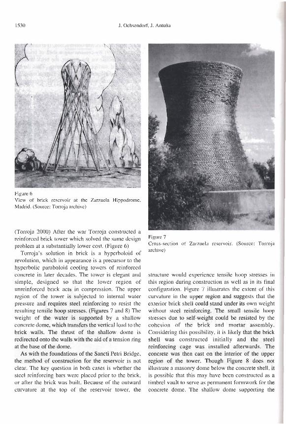
Figure 6 View of brick reservoir at the Zarzuela Hippodrome, Madrid. (Source: Torroja archive)
(Torroja 2000) After the war Torroja constructed a reinforced brick tower which solved the same design problem at a substantially lower cost. (Figure 6)
Torroja 's solution in brick is a hyperboloid of revolution, which in appearance is a precursor to the hyperbolic paraboloid cooling towers of reinforced concrete in later decades. The tower is elegant and simple, designed so that the lower region of unreinforced brick acts in compression. The upper region of the tower is subjected to internal water pressure and requires steel reinforcing to resist the resulting tensile hoop stresses. (Figures 7 and 8) The weight of the water is supported by a shallow concrete dome, which transfers the vertical load to the brick walls. The thrust of the shallow dome is redirected onto the walls with the aid of a tension ring at the base of the dome.
As with the foundations of the Sancti Petri Bridge, the method of construction for the reservoir is not clear. The key question in both cases is whether the sleel reinforcing bars were placed prior to the brick. or after the brick was built. Because of the outward curvature at the top of the reservoir tower, the
Figure 7 Cross-section of Zarzuela reservoir. (Source: Torroja archive)
structure would experience tensile hoop stresses in this region during construction as well as in its final contiguration. Figure 7 illustrates the extent of this curvature in the upper region and suggests that the exterior brick shell could stand under its own weight without steel reinforcing. The small tensile hoop stresses due to self-weight could be resisted by the cohesion of the brick and mortar assembly. Considering this possibility. it is likely that the brick shell was constructed initially and the steel reinforcing cage was installed afterwards. The concrete was then cast on the interior of the upper region 'Of the tower. Though Figure 8 does not illustrate a masonry dome below the concrete shell. it is possible that this may have been constructed as a timbrel vault to serve as permanent formwork for the concrete dome. The shallow dome supporting the

Eduardo Torroja ,md «Ceramica Armadn» 1531
c.ass SlCTlOH OF U/CI( SnwcTUlI
Figure 8 Drawing of reinforcing delail for the Zarzuela reservoir. (Source: Torroja archive)
wafer would act predominantly in compression under its own weight, and therefore could have been built as a brick or tile dome.
TUE CHURCH OF PONT DU SUERT (1952)
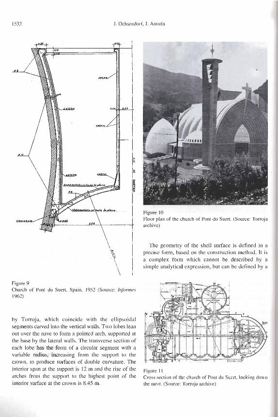
By 1950, Torroja was known internationally and had recently designed various systems of reinforced ooncrete shells for long-span roofs, such as the central halll of ENASA of 1948 and the roof for the experimental laboratory for the Instituto Tecnico de la Construccion. (Antuiia 2002) Upon returning from South America in 1952, Eduardo Torroja started work on several church projects in the Pyrenees Mountains. These projects, the churches of Xerallo, Pont de Suert, and the mountain refuge of Sancti Spirit, have been ignored, if not discounted, by historians and critics unimpressed by their formal qualities.4 We will focus on the largest and most significant of these projects, the church of Pont du Suert in Llerida. (Figures 9-15)
'fhe church of Pont de Suert has four parts: a long nave, terminating in an apse, with a small chapel and
another room connected on the side. The reinforced concrete floor structure spans between masonry walls of 1.38 m thickness. The low masonry walls support the roof structure, which is a curving shell of lightly reinforced brick. The roof shells were built with minimal fonnwork and are of greatest interest to the present discussion. Each shell is made of two to three layers of thin bricks (rasillas), covered on the exterior with 3 cm of mortar reinforced with a 4 mm steel mesh. In each one of the four parts the form of the roof is different, but the constnlction technique is the same throughout.
A study of the structure of the nave serves to illustrate the constructive system. The exterior of the nave is a rectangular plan 13 III wide and 20 m long, plus 8.5 m of the apse and 2.5 of the low entrance to the choir. The lateral walls are of stone masonry 2.75 m high, measured from the plane of the interior floor, and 1.35 m wide, including an exterior fa<;:ade of one layer of cut stone. The top surface of the walls forms a continuous plane to support the roof. For the interior face, the mass of the wall is decreased by repeating ellipsoidal niches 3 m wide. The roof of the nave is divided into five independent sections, called <<lobes»
1532 J, Ochsendorf, J, Anluija
Figure 9 Church of Ponl du Suen, Spain, 1952 (Source: InJormes 1962)
by Torroja, which coincide with the ellipsoidal segments carved into the vertical walls, Two lobes lean out over the nave to form a pointed arch, supported at the base by the lateral walls, The transverse section of each lobe has the form of a circular segment with a variable radius, increasing from the support to the crown, to produce surfaces of double curvature, The interior span at the support is 12 m and the rise of the arches from the support to the highest point of the interior surface at the crown is 8,45 m,
Figure 10
I 1
Floor plan of the church of Pont du Suer!, (Source: Torroja archive)
The geometry of the shell surface is defined in a precise form , based on the construction method, It is a complex form which cannot be described by a simple analytical expression, but can be defined by a
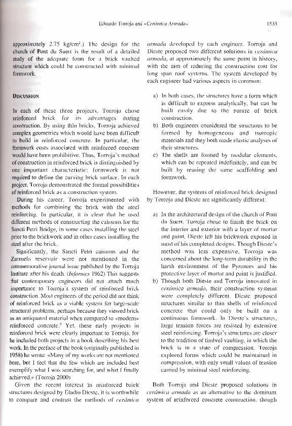
Figure 11 Cross-section of the church of Pont du Suert. looking down the nave, (Source: Torroja archive)

Eduardo Torroja and "Cenlmica Armada» 1533
series of transverse sections. During construction, a thin metal framework served as a guide for the placement of the first layer of the thin bricks. The
surface can be generated by displacing a curve of a circular segment from another similar curve with a
different radius C,.. (Figures 12 and 13). The interior
surface of the resulting figure is an arc segment of circumference Cl' The curves generated are contained in a horizontal plane which rotates on an axis passing
through the center of the curve C;. The sllli'ace is defined bylhe coordinates of 26 transverse sections
contained within the plane and supporting points of the exterior curve of the lobe, as indicated in the
figure . The lines that define the edges of the shell are curves whose transverse projection is the curve C;, and in the longitudinal plane it is a curve
corresponding to the expression:
y = 0,59x1.249 (I)
The curve is defined by the condition that its vertical asymptote is perpendicular to the ellipsoidal section of
Ihe lower niche. Figure 12 indicates the center of gravity of each curving section defined by the surface
eg
, and the centroid of each of the arches, Cc' To construct the roof, 26 guides were used
following the form defined by the 26 arc segments
indicated in Figures 13 and 14. The guides were )Iaced on lightweight scaffolding. used to define the
,.- Ce
I. _
~4.oi--296.0 ' -.:.., -' '----5 12,O----l<98
igure 12
+3.58 V.
eomctry or the " lobe» for the church of Pont du Suer\. ;ource: Antufia 2(02)
form of the first layer of the bricks, which would become the lobe. The first layer was placed with a fast-setting gypsum mortar and sUQsequent layers were built with a cementitious mortar in the same
lTIanner as the timbrel vaulting constructed by Rafael
Guastavino. (Huerta 2001) The metal guides also helped to support the weight of the roof until the two
sides of the pointed arch met at the crown. After the two sides were joined, the structure was stable and
worked in compression predominately. A longitudinal beam at the crown of the arches connects
all of the lobes along the exterior surface, without being visible on the interior. This provides a point load at the crown of the arch which causes the ,internal
line of thrust in the roof to more closely follow the center of gravity of the section, reducing the
eccentricity and any associated bending stresses in the brick shell. (Figure IS)
To analyze the structure Torroja treated it as a fixed-end arch with a hinge at the crown, which is a
structure with two degrees of static indeterminacy, Torroja carried out an elastic analysis, considering the
material as isotropic, homogeneous and perfectly elastic. He determined the geometrical characteristics
of the various sections, area and moment of inertia, and with these values he calculated the internal stresses in the brick roof. Finally , he applied the same
procedure to the roofs of the apse and the baptistery. The thrust of the nave is resisted by the lightly
reinforced concrete walls formed on each side of the niches in the walls. The shell works in compression
Figure 13 Three-dimensional drawing of an individual lobe. (Source: Antulia 2002)

1534 J. Ochsendorf, J. Antuiia
ALZADO "~T~R/OR De LOBuLOS
t- · ~.,
~
~;,
Figure 14
~At.A / :Z5
u
u
v
"
"
I
~~--~H I
.~ __ . __ .J I i
Elevation of the intersection between two lobes, including a table giving the geometry. (Source: Torroja archive)
'" /;;:::- .
.- ,/ / . 't
~.
. . . . .. I, . - . .. .1lt . 1· - .:~ Jj -' I ..
\ .
Figure 15 Graphic calculation of the internal line of compression acting in the arch of the church of Pont du Suert under se lfweight. (Source: Torroja archive)
predominantly, using a thickness of 17 cm, so that the slenderness ratio is 70. The form of the structure is designed to be maintained in compression and the internal steel reinforcing is kept to a minimum.
In his earlier projects of reinforced concrete shells, Torroja used sUli'aces of a simple geometry: spherical domes , cylindrical shells, or ellipses. He imposed this limitation because it allowed him to make an elastic analysis of the s tructure by integrating the equilibrium equations, which had only been established for simple geometries. However, beginning with the church of Pont du Suert, he proposed more complex form s culminating with the roof of the club Tachira de Caracas of 1957. In the church designs, the small span and slenderness of the shell provided a stable surface of double curvature with very low stresses in the material. (At the shell support for the nave of the church of Pont du Sue rt , the compressive stresses in the concrete are
Eduardo Torroja and "Cere/mica Armad{/), 1535
appmximately 2.75 kg/cm2) The design for the church of Pont du Suert is the result of a detailed study of the adequate form for a brick vaulted structure which could be constructed with minimal fOlmwork:.
DISCUSSION
In each of these three projects, Torroja chose reinforced brick for its advantages during construction. By using thin bricks, Torroja achieved complex geometries which would have been difficult to lDuild in reinforced concrete. In particular, the formwork costs associated with reinforced concrete would have been prohibitive. Thus, Torroja's method of construction in reinforced brick is distinguished by one important characteristic: form work is not required to define the curving brick sutface. In each project, Torroja demonstrated the formal possibilities of reinforced brick as a construction system.
Durillg his career, TotToja experimented with method's for combining the brick with the steel reinforcing. In particular, it is clear that he used diffel"ent methods of constructing the caissons for the Sancti Petri Bridge, in some cases installing the steel prior to the brickwork and in other cases installing the steel after the brick.
Significantly, the Sancti Petri caissons and the Zarzuela reservoir were not mentioned in the conunemorative journal issue published by the Torroja Institute after his death. (lnlormes 1962) This suggests that contemporaIY engineers did not attach much importance to TotTOja's system of reinforced brick construction. Most engineers of the period did not think of reinforced brick as a viable system for large-scale SlllIctural problems, perhaps because they viewed brick as an antiquated material when compared to «modern» reinforced concrete.' Yet, these early projects ill reinforced brick were clearly imp0I1ant to Ton'oja, for he included both projects in a book describing his best work. In the preface of the book (originally published in 1958) he wrote: «Many of my works are not mentioned here, but I feel that the few which are included best exemplify what I was searching for, and what I finally achieved.» (Torroja 2000)
Given the recent interest in reinforced brick structures designed by Eladio Dieste, it is worthwhile to compare and contrast the methods of ceramica
armada developed by each engineer. Torroja and Dieste proposed two different solutions in cerful1ica armada, at approximately the same point in history, with the aim of reducing the construction cost for long span roof systems. The system developed by each engineer had various aspects in common:
a) In both cases, the structures have a form which is difficult to express analytically, but can be built easily due to the nature of brick construction.
b) Both engineers considered the structures to be formed by homogeneous and isotropic materials and they both made elastic analyses of their structures.
c) The shells are formed by modular elements, which can be repeated indefinitely, and can be built by reusing the same scaffolding and formwork.
However, the systems of reinforced brick designed by Torroja and Dieste are significantly different:
a) In the architectural design of the church of Pont cll! Suert, Torroja chose to finish the brick on the interior and exterior with a layer of mortar and paint. Dieste left his brickwork exposed in most of his completed designs. Though Dieste's method was less expensive, Torroja was concerned about the long-term durability in the harsh environment of the Pyrenees and his protective layer of mortar and paint is justified.
b) Though both Dieste and Torroja innovated in
ceramica armada, their construction systems were completely different. Dieste proposed structures similar to thin shells of reinforced concrete that could only be built on a continuous formwork. In Dieste's structures, large tension forces are resisted by extensive steel reinforcing. Torroja's structures are closer to the tradition of timbrel vaulting, in which the brick is in a state of compression. Torroja explored forms which could be maintained in compression, with only small values of tension carried by minimal steel reinforcing.
Both Torroja ancl Dieste proposed solutions in ceramica armada as an alternative to the dominant system of reinforced concrete construction, though

1536 J. Ochsendorf. J. Antui'ia
few engineers have pursued this idea in recent years.
Unlike Dieste. Torroja's proposals have not been
further explored by cngineers or historians of
constrLtction since his dea th in 1961.
CONCt.llSJON
By the 1950·s . the construction of thin concrete shells
was an expensive solution due III the incre'-lsed costs
of formwork and luhor. Before steel con.';tructioll
became the most common structural solution for long
spans. Torroja and others studied alternativcs to
reinforced concrete. which would not require
expensive formwork syst e ms. The construction
aspects of these projects :Ire of historical interest
because they offer alternatives for an cconomical
construction method using local materials.
TOlToja ' s experimentalion with reinforced brick
was the result of hi s civil engineering education
combined with his knowledge of the vernacular
tradition of tile vault construction in Spain. The work
of TOIl'Oja and Dieste sugges ts that brick is a useful
material for structural design and construction,
though these possibilities are largely unexplored in
structural e ngineering today.
NOTES
I. Coltancin received a patent in France in 1890 and in Spain ill 1891. His Spanish patent. No. 1230 I. was titled «objects of plastic mate rial , with metallic
reinforcing. composed of a wire or other mesh» (O"j~/()s de lIIaleria phistica COli a/"ll/{/Z<>1l lIIetlili('{/ COIl1I"({'sta de tcjidos de alall/bre 11 otms) . A Spanish
competitor, Antonio Macia Llusa received a patent in 1894 (No. 155(2) titled «A system of construction by
means of re inforcing form ed of steel wire mesh . combined with v~rious layers o r brick or hollow tiles. c()ver~d with mortar or a layer of concrete» (l/Il sis/ellll/ de cOllslruccioll por lIIedio de anlll/Z(JII~s.fomu/(los por l11(dlas de a/oJllhres de ((("('ro,. . c01llhillOt/flS COli
I'arias CIII)(IS de ladril/o.\· 0 /'{Isil/o.\· . ,~lIll1cielldo () HO /a o/Jra COli 1I10rfero (I Will ('{{PO de hOrJJlig{Ji l).
Several water reservoirs were built in this system at the end or the 19'" century in Spain.
2. It seems that Rarael Guastavino Jr. employed metallic reinforc ing in somc of his brick she ll structures in the
United States. though l110re research is required to
document the extent of this practice.
3. This is thc sam e construction system that the GU<lstavino father and son employed with wide success in the United States. (Huena 2001)
4. One critic wrote that thcse mountain churches were «among the most ridiculolls monstrosities in modern
Spanish archit cct ure. » (Fern,indel and Navarro 1999)
). This situation is reminiscent of what historian Eric
Schallherg (199Xj has termed the «progress ideology »
of metal. when engineers nt'g1ected the advantages of wood as a structural materia l for airplanes during the 1930' sand 1940· s. choosing metal instead.
REFEHENCES J.JST
Antuiia Bernardo. Jo'lqufn. 2002 . La.\' cstructllras de edijicucirJ/l de Edllardo Torroia [Hire/. Doctoral Thesis. Escuela Tccnica Superior de Arquitectura de Mad rid ,
Madrid. Billington. David . 198). Tile TiMer and the Bridge: The
Nel\' Art of StJ'/lCllIl'l/1 ElIgineerillg. Princcton University Press. Princeton. NJ.
Collins. George. 1968. "The Transfer of Thin Masonry Vaulting from Spain to America,» JOllmal of the Society o/Archileclllml Historialls, 27: 176-201.
Fernandez Ord6iiel.. Jose Antonio and Navarro Vera. Jose
Raman. 1999. Edllardo Torroia Miret. Engineer. Ediciones Pronaos S,A .• Madrid.
Frampton. Kennct h. 1995. Stlldies in Tectonic Cultllre. MIT Press. Cambridge. Massachusetts. pp. 54- 56.
Huerra Fernande7.. Santiago. 200 I. Las B6vedas de Guas/aFino en America. CEDEX. Madrid.
Inj(mn es de la Con.\'truccioll. 1962. No. 137. Institllto
Eduardo Torroja de la Construccitin y del Cemento. Madrid.
Jimenel. Torreci 11 as. Antonio (Ed. ). 200 I. Eludio Die.l'le 1'143-11)1)6. 4th Edition. Junta de Andalucia. Seville.
Ochsendorf. John. 2003. «Eladio Dieste as Structural
Artist». in Eiadio Diestc: 11l1I""alion.> in SIJ'lIclllrol Art. Stanford Andcrson. Editor. Princeton Architectural Press. Princeton. NJ.
Pedreschi. Rerno. 2000. t:lodio Dieste. Thomas Telrord Publishing. London.
Sch~t7.berg. Eric. 1998. Wings (~f Wood. Wings of Mellll: CllllUre allll Techllical Choice in Alllerican Airplalle [\!III/Nillls. 11)14- 11)45. Princeton University Press .
Princeton. TOllllow. Jos. 20tJl. «La b(iveda tabicada a la catalana y cl
nacilllien lo de la "cel'<irnica armada" en Uruguay.» in l.llS
Hr>l'cdos de GII({s/(/\"iIlO ell AIJu!rico. Santiago Hucrta.
Editor. CEHOPU. Madrid. pp, 241 - 25:1.
Torroja. Fdu'lrdo. 2000. The SII'If(' tllres of 1:(/lIardo "')rr{~ia. 2,,·1 Edition. (in Eng lish). CEDEX. Madrid. (Fi rst edition .
1958. F.W. Dodge Corp .. Ncw York.).