vol.19 no.3 january 2016 issn:1174-3646 · masonry performs much better than rc frame ... be...
TRANSCRIPT

Earthquake Hazard Centre Newsletter, Vol. 19 No 3, January 20161
Vol.19 No.3 JANUARY 2016 ISSN:1174-3646
Editorial
This issue is devoted to disseminating a very important new publication on confined masonry. Given that confined masonry performs much better than RC frame infills or unreinforced masonry construction in earthquakes, this superior method of building needs to be widely introduced. Selected sections of the “Construction Guide for Low-Rise Confined Masonry Buildings” prepared by Tom Schacher and Tim Hart therefore comprise this issue. Readers are encouraged to download this Confined Masonry Network publication and become acquainted with all aspects of constructing low-rise confined masonry buildings.
Introduction to “Construction Guide for Low-Rise Confined Masonry Buildings”
In most countries modern low-rise residential construction is made either of unreinforced masonry or reinforced concrete moment frames with masonry infill walls. Experience has shown that both systems can be significantly affected by earthquakes. Unreinforced masonry buildings cannot deal adequately with horizontal forces, while reinforced concrete frames are difficult to build correctly. Too many details have to be observed and properly implemented, a challenge beyond the capabilities of self-builders or workers with no formal training. A simpler and more forgiving construction technology is needed to ensure safe construction.
Confined masonry combines elements of both systems, but it is a simple and forgiving construction method which has demonstrated good performance in past damaging earthquakes in Latin America. It is widely practiced in Latin America and Mediterranean Europe, and it has been the subject of lab testing and research studies, and has been incorporated in national building codes. In some
Asian countries, such as Indonesia and China, confined masonry is regarded as a standard construction technique, while on the Indian subcontinent confined masonry has been actively promoted over the last decade.
As confined masonry is a construction system that has been developed by practitioners in various countries in parallel, there is a lack of uniform rules on how it should be implemented correctly. In 2008 the Confined Masonry Network decided to tackle this issue by compiling a set of common rules from the various existing codes and guidelines on confined masonry and use them to develop a uniform set of guidelines.
A first result has been the Seismic Design Guide for Low-Rise Confined Masonry Buildings, published by the Network in 2011, which provides prescriptive design provisions for engineers who want to use this construction system.
The present Construction Guideline for Low-Rise Confined Masonry Buildings addresses the needs of small-scale contractors, technicians, government staff, architects as well as non-governmental organizations involved in post-disaster reconstruction. The guide has been written with users with various professional backgrounds in mind, including a workforce with little formal training. As a consequence this guide not only shows the practical detailing of confined masonry construction, but also offers a wealth of basic information on good construction practices in general.
A note of caution: this guide explains how to build earthquake resistant houses with a maximum height of two stories (ground floor and upper floor). For taller buildings an experienced engineer must be consulted for specific calculations!
Finally, a third volume entitled Engineered Guidelines for Confined Masonry is under development and will be made available in 2016.
Contents
Editorial A Summary of “Construction Guide for Low-Rise Confined Masonry Buildings”
p.1p.2

Earthquake Hazard Centre Newsletter, Vol. 19 No 3, January 20162
A Summary of “Construction Guide for Low-Rise Confined Masonry Buildings” prepared by Tom Schacher (Switzerland) and Tim Hart (USA). Confined Masonry Network, October 2015.
PArt I: GenerAl ASPeCtS of ConfIned
MASonry ConStruCtIon
Why use confined masonry?
Confined masonry construction has been used during
the last half century in various parts of the world.
Researchers in Latin American and European countries
have studied its behavior and refined the technique, and
governments have promoted its application with very
satisfactory results. The severe 2010 earthquake in Chile
(M 8.8) caused a relatively low number of victims, in part
due to the wide use of confined masonry construction for
single family and apartment housing.
Before going into the details of confined masonry
construction, it is worthwhile to look at the two of the
most common construction methods used for low-rise
housing. They are unreinforced masonry and reinforced
concrete frames with infill walls. It is important to
understand their weak points which can be avoided by
employing the confined masonry construction technology.
Unreinforced masonry in earthquake prone areas
Unreinforced masonry works well in areas with no
earthquakes because masonry is strong in compression
and the walls only have to bear vertical loads. In addition,
masonry construction provides thermal comfort and
durability. However, in earthquake-prone areas, horizontal
loads due to earthquake shaking must be taken into
account. Unreinforced masonry walls have some strength
to resist lateral forces. However, it’s limited and once it’s
exceeded the walls degrade rapidly, never to recover, like a
stack of books on a wobbly table (Figure 1).
Figure 1: Stack of books not attached together will fall apart when the table gets shaken
Figure 2: Reinforced concrete ties hold the house together like a string around a stack of books

Earthquake Hazard Centre Newsletter, Vol. 19 No 3, January 20163
In a building where walls are not well-connected to the
floors and roof by reinforcing or confining elements, the
walls will separate at the corners and the structure will
undergo serious damage or collapse.
When unreinforced masonry is confined by concrete tie
elements, however, it greatly slows down the degradation
of the walls. Similar to a pile of books held together by
a string, the books will still slide around but the string
prevents the stack from falling apart. That’s exactly
what confined masonry is doing by holding all elements
together with reinforced concrete ties (Figure 2).
Reinforced Concrete frames with infill walls in earthquake prone
areas
In confined masonry the masonry walls are built first,
and then concrete vertical and horizontal ties are poured
around them. By contrast, in framed infill construction
the concrete is poured first, then the masonry infill is
placed (Figure 3).
Reinforced concrete (RC) frame structures with infill
walls are much more complex to build than they appear to
the common worker. Concrete is not simply ‘a glue’ that
holds everything together. Instead, the concrete frame
is the primary force resisting element. The masonry is
placed after the concrete and is assumed to act as a non-
load bearing partition. Because the concrete is the seismic
load resisting element, special detailing is needed in the
frame. This special detailing makes reinforced concrete
frames very sensitive to implementation errors which can
be fatal under earthquake conditions. A whole series of
steps must be made properly:
• the rebar has to be placed in exactly the right position,
• there must be enough space around the rebars to
allow for sufficient concrete cover,
• rebar connection details must be correct,
• concrete has to be made in the right proportions and
has to be mixed perfectly,
Figure 3: Inverse construction sequence in confined masonry compared to RC frames with infill walls
RC frames with infill walls: concrete frame first, walls later
Confined masonry: walls first, concrete ties later
• pouring of concrete and its compaction must be done
to a high standard (very difficult to achieve without a
needle vibrator),
• curing must be done properly to ensure correct
hardening of the concrete.
The stress in the concrete moment frame members is high
because the infill masonry is assumed not to contribute
any strength to the wall. All vertical and horizontal loads
have to go through the frame and its relatively narrow
joints. Thus, there is no space for error!
Earthquake Hazard Centre Newsletter, Vol. 19 No 3, January 20164
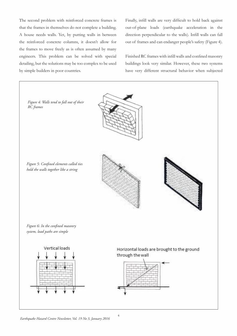
Figure 6: In the confined masonry system, load paths are simple
Figure 5: Confined elements called ties hold the walls together like a string
Figure 4: Walls tend to fall out of their RC frames
The second problem with reinforced concrete frames is
that the frames in themselves do not complete a building.
A house needs walls. Yet, by putting walls in between
the reinforced concrete columns, it doesn’t allow for
the frames to move freely as is often assumed by many
engineers. This problem can be solved with special
detailing, but the solutions may be too complex to be used
by simple builders in poor countries.
Finally, infill walls are very difficult to hold back against
out-of-plane loads (earthquake acceleration in the
direction perpendicular to the walls). Infill walls can fall
out of frames and can endanger people’s safety (Figure 4).
Finished RC frames with infill walls and confined masonry
buildings look very similar. However, these two systems
have very different structural behavior when subjected

Earthquake Hazard Centre Newsletter, Vol. 19 No 3, January 20165
Figure 7: Main elements of a confined masonry building
Slab:Slabs distribute earthquake loads to all the walls. They have to be well connected with the walls by means of horizontal and vertical ties.
The main characteristics of a confined masonry building at a glance
Horizontal and vertical ties:The vertical ties (“tie-columns”) are the vertical confining concrete elements of the walls. The horizontal ties (Plinths and ring beams) are the confin- ing concrete elements above and below the walls. All ties must be securely fastened to one another.
Solid walls:Each facade should contain at least one solid wall panel without openings.
Foundation:Foundations must be continuous to support the loads transferred to the ground by the walls.
Openings:All openings must be confined. Openings should not be too large and should be well distributed.
Masonry Walls:Walls are the most impor-tant elements in a confined masonry structure. They transmit all vertical and horizontal) forcesto the ground. Walls may be built using various masonry units of adequate quality and strength. Walls must be well distributed though the building plan.
to lateral loads. In a RC frame system the load path is
complex and all forces have to be carried by beams and
columns and beam-column joints, while the load path in
a confined masonry system is simple and straightforward
because the forces are carried to the ground by the walls;
it is a load-bearing wall system.
Confined Masonry Basics
In the confined masonry system the walls carry all the
vertical and horizontal loads. Walls are held together by
reinforced concrete confining elements that improve the
in-plane strength of these masonry walls, resisting the
shear forces induced by an earthquake (Figure 5).
While detailing of rebar connections must still be correct,
in particular the lap lengths, confined masonry structures
are more tolerant of bad execution (Figure 6). If the
concrete in the reinforced concrete ties is less than perfect,
the system still works. However, the better the execution,
the stronger the building!
Main components of a confined masonry building
The shape of a building plan and the structural elements
of a building influence earthquake performance. The
following rules in Figure 7 apply to most construction
technologies and building sizes.
Earthquake Hazard Centre Newsletter, Vol. 19 No 3, January 20166
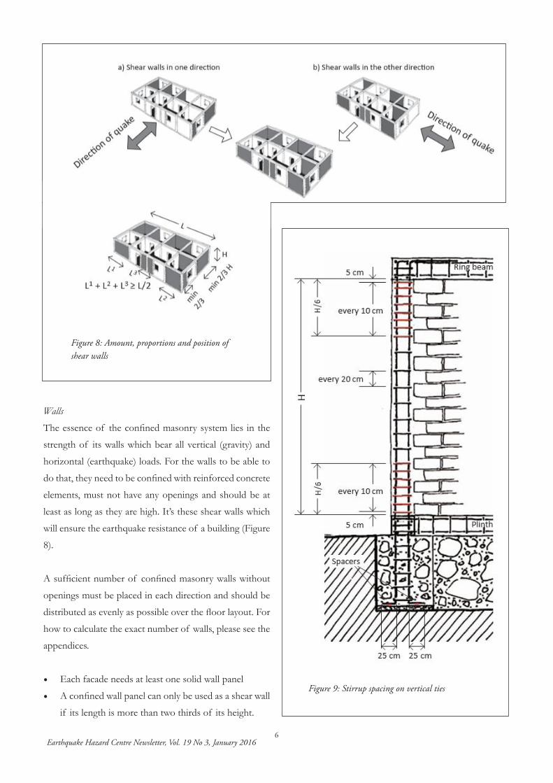
Figure 9: Stirrup spacing on vertical ties
Walls
The essence of the confined masonry system lies in the
strength of its walls which bear all vertical (gravity) and
horizontal (earthquake) loads. For the walls to be able to
do that, they need to be confined with reinforced concrete
elements, must not have any openings and should be at
least as long as they are high. It’s these shear walls which
will ensure the earthquake resistance of a building (Figure
8).
A sufficient number of confined masonry walls without
openings must be placed in each direction and should be
distributed as evenly as possible over the floor layout. For
how to calculate the exact number of walls, please see the
appendices.
• Each facade needs at least one solid wall panel
• A confined wall panel can only be used as a shear wall
if its length is more than two thirds of its height.
Figure 8: Amount, proportions and position of shear walls
Earthquake Hazard Centre Newsletter, Vol. 19 No 3, January 20167
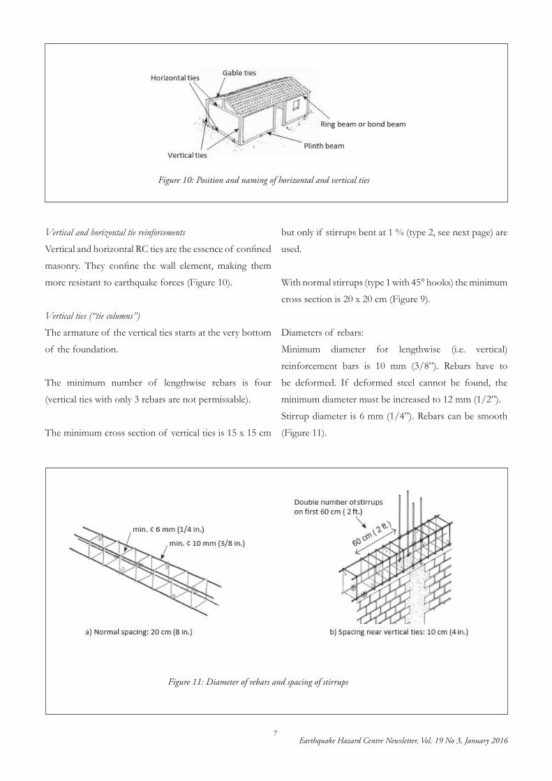
Vertical and horizontal tie reinforcements
Vertical and horizontal RC ties are the essence of confined
masonry. They confine the wall element, making them
more resistant to earthquake forces (Figure 10).
Vertical ties (“tie columns”)
The armature of the vertical ties starts at the very bottom
of the foundation.
The minimum number of lengthwise rebars is four
(vertical ties with only 3 rebars are not permissable).
The minimum cross section of vertical ties is 15 x 15 cm
but only if stirrups bent at 1 % (type 2, see next page) are
used.
With normal stirrups (type 1 with 45° hooks) the minimum
cross section is 20 x 20 cm (Figure 9).
Diameters of rebars:
Minimum diameter for lengthwise (i.e. vertical)
reinforcement bars is 10 mm (3/8”). Rebars have to
be deformed. If deformed steel cannot be found, the
minimum diameter must be increased to 12 mm (1/2”).
Stirrup diameter is 6 mm (1/4”). Rebars can be smooth
(Figure 11).
Figure 11: Diameter of rebars and spacing of stirrups
Figure 10: Position and naming of horizontal and vertical ties
Earthquake Hazard Centre Newsletter, Vol. 19 No 3, January 20168
,
Earthquake Hazard CentrePromoting Earthquake-Resistant Constructionin Developing Countries
The Centre is a non-profit organisation based at the School of Architecture, Victoria University of Wellington, New Zealand.
Director (honorary) and Editor: Andrew Charleson, ME (Civil)(Dist), MIPENZResearch Assistant: Caitlyn Lee, BE (Eng. Science), BAS
Mail: Earthquake Hazard Centre, School of Architecture,PO Box 600, Wellington, New Zealand.Location: 139 Vivian Street, Wellington.Phone +64-4-463 6200 Fax +64-4-463-6024Email: [email protected]
The Earthquake Hazard Centre Webpage is at:http://www.vuw.ac.nz/architecture/research/ehc
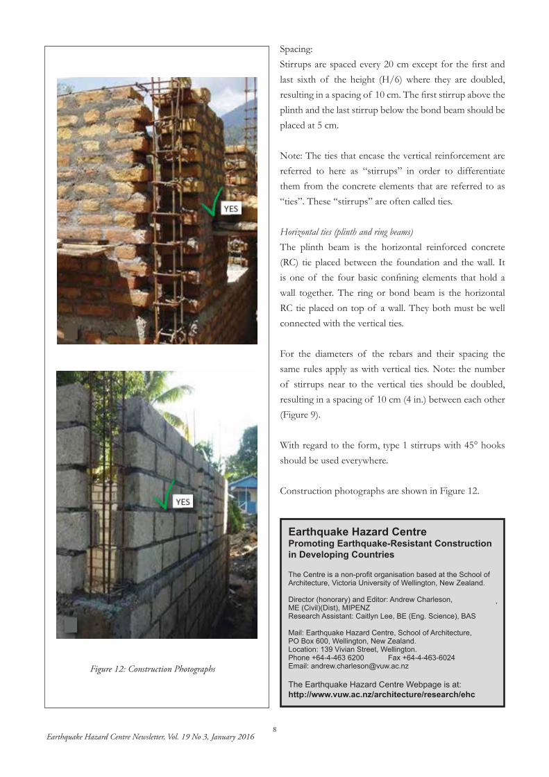
Spacing:Stirrups are spaced every 20 cm except for the first and last sixth of the height (H/6) where they are doubled, resulting in a spacing of 10 cm. The first stirrup above the plinth and the last stirrup below the bond beam should be placed at 5 cm.
Note: The ties that encase the vertical reinforcement are referred to here as “stirrups” in order to differentiate them from the concrete elements that are referred to as “ties”. These “stirrups” are often called ties.
Horizontal ties (plinth and ring beams)The plinth beam is the horizontal reinforced concrete (RC) tie placed between the foundation and the wall. It is one of the four basic confining elements that hold a wall together. The ring or bond beam is the horizontal RC tie placed on top of a wall. They both must be well connected with the vertical ties.
For the diameters of the rebars and their spacing the same rules apply as with vertical ties. Note: the number of stirrups near to the vertical ties should be doubled, resulting in a spacing of 10 cm (4 in.) between each other (Figure 9).
With regard to the form, type 1 stirrups with 45° hooks should be used everywhere.
Construction photographs are shown in Figure 12.
Figure 12: Construction Photographs