virtual prototyping for training in engineering design...dep. of mechanical engineering. ets...
TRANSCRIPT

Virtual Prototyping for Training in Engineering Design
ROMERO, G.; MAROTO, ;J. MARTÍNEZ, M. L.; FÉLEZ, J. Dep. of Mechanical Engineering. ETS Ingenieros Industriales.
Universidad Politécnica de Madrid José Gutiérrez Abascal, 2. 28006 Madrid.
SPAIN
Abstract: This paper presents a development consisting of a virtual reality application used to move, view and manipulate mechanisms. These mechanisms can be assembled or disassembled and checked if work properly. A virtual environment can be used and the mechanism can be observed by different ways using a HMD or stereoscopic glasses. The main object of this work is the development of new methodologies for training in mechanical design adapting traditional subjects as Engineering Drawing to the new technologies of visualization and simulation raised in the last years. In order to use these mechanisms in Internet, the program let us obtain a file that can be view with an Internet explorer program.
The goal is to develop modules of design engineering through Internet where the three-dimensional and interactive graphics are the most innovative aspect and attractiveness. One of the most important decisions in the development of the project was to select the proper technology of three-dimensional graphics. These graphics had to allow to the interactivity with the user as far as navigation (zoom, rotation and pan) and as far as detection of events so they had to be programmable. In addition characteristics as the small size of file and the possibility of streaming were important.
About 800 3D models have been developed where the user can visualize the model from any point of view and size and many of them can interact with him, executing disassemblies or processes for example.
Key-Words: WEB3D, Virtual Reality, computer aided learning, interactive graphics, Internet. Collaborative Design
1. Introduction One of the main goals of the technical drawings is
the work and the comprehension of the assembly drawings
One of the main problems one has to face is that, as it is usually working with real drawings, sometimes its difficulty or complexity, other times the people’s lack of spatial vision makes difficult understanding the subject properly.
A good solution is having physically the real assemblies or the machines, as well as the pieces that form the drawings. With these assemblies it is allowed observing physically how they are and observe the shape of the elements under any point of view. We can study the way they are fixed, how ones fit in others, and as a result, it could be possible to study how the assembly works in order to achieve a better understanding.
Regardless, due to the extension and variety of the assemblies used, and that in some cases, its physical size and weight makes them unmanageable, being able to dispose of them all and manipulate them easily is almost impossible.
A computer solution seems appropriate to solve these kinds of problems. Computers have not problems of accessibility and use unless than imposed by the program. They allow developing an application to reconfigure easily the assemblies being able to modify them easily. And, as a result, this technique is comprehensible for almost all the students.
For the reasons stated above, the solution given in this paper is proposed. With it, it is intended to develop an application based on virtual reality techniques that will allow the construction of geometric models of the assemblies. These models will be implemented with virtual reality software aiming the computer simulation of those assemblies.
Internet has supposed one of the best tools in the educative field. The possibility of arranging almost limitless textual and graphical information is the first sign of its potentiality. The first specification of VRML 1,0 begins at the end of 1994. This language was the first step to obtain interactive virtual worlds of low cost by means of Internet Since standard VRML 2,0 (1997) [3] arose, many educational applications have been made from Internet taking advantage of the
Proceedings of the 8th WSEAS Int. Conference on Automatic Control, Modeling and Simulation, Prague, Czech Republic, March 12-14, 2006 (pp182-188)

improvements that the graphs 3D provide. The CosmoPlayer [4] browser popularized its use At that moment at which project WEBD began some educational sites contained images 3D based on VRML: Actually many of these pages are not available. VRML has been used like viewer or exit of results in multitude of sites of engineering like the David Keeenan’s Internet Railroad [5] that allows the configuration of trains with different elements or as a viewer of different solutions from design of common objects of the Technology High School de Bergen [6]. At the moment any program CAD offers a VRML output of the design 3D in course. In the field of medicine VRML it has been used like a viewer of bones and other relative elements (surgical tools and so on) and very successfully as a surgical simulator, the WebSET Project, to train in operations like lumbar puncture in the Manchester University [7]
2. WEB3D technologies The final goal of the project is to evaluate the possibilities that offer the WEB3D technologies for Internet in the field of the education. The first technology that allowed the 3D interactive worlds visualization through Internet was the standard VRML whose last update was in 1997 [3]. From then a standard specification did not become until the middles of 2002, creating emptiness that a big amount of software companies (we have been detected around 45 companies) decided to approach developing the named technologies WEB3D. These technologies were focused at first to being 3D product viewfinders for the sales by Internet. In general they include several technologies that optimise the mesh of the 3D models, obtaining very low rates of downloading. They use also streaming and optimised textures. The render kernels are very good and offer a higher quality to the obtained one with VRML. On the other hand the elaboration of the standard of 3D graphics, the X3D for Internet, has not been made until end of year 2002 reason why WEB3D graphics have a high level of market.
Ever since the project began we have seen how these technologies have become rich and modifying. The way of programming of some of them has suffered up to 4 changes of syntax, transferring a high insecurity to the programmer. They have incorporated the possibility of including flash movies, videos, SVG graphics... allowing the creation of dynamic textures. More detailed study of these technologies is offered in [3].
These technologies can be grouped in: • Technologies based on XML: One file
contains the geometry and other the transformations and the possible interactions
of the user with the virtual world. These require plugins for their visualization.
• Technologies based on Java3D. Plugin is not necessary although they are slower.
• Own technologies developed by the commercial companies requiring plugin
By means of these technologies and in particular by the offered by Viewpoint and Actify more than 2,000 3D interactive models have been developed:
• To visualize simply 3D objects (with zoom functions, pan and rotation). In figure 1 the high quality obtained is observed.
• To offer procedures or methods, for example how to determine the intersection between two solids in the dihedrical system. The rebatment of a plane is offered in figure 2.
• To offer assemblies/disassemblies of devices (figure 3). We use collision detection and transparencies to improve the skills of the students.
Figure. 1 : Visualization of some accessorize elements from the design engineering module
Very attractive 3D worlds for the user have been
developed where in addition the behaviour of those worlds is included. The most stable technologies seem to be Viewpoint [4] and Cult3D [5].
For the project the models are made from 3Dstudio Max optimising the mesh. Also animations have been defined if it were necessary. The own companies provide programs to convert to WEB3D formats. In order to add interactivity it is necessary to program either in agreement with the specific syntax of each one of them, or adding routines in JavaScript, since these technologies were destined to the electronic commerce and have limited capacities of interactivity and mainly of programming.
Proceedings of the 8th WSEAS Int. Conference on Automatic Control, Modeling and Simulation, Prague, Czech Republic, March 12-14, 2006 (pp182-188)

(b)
Figure. 2 : Different assemblies with transparencies to show the inner parts and devices that can be
exploded
3. Project description Software based in virtual reality techniques will be developed to allow the interaction with assemblies.
The project goal is to develop a software tool that allows working with a physical assembly and interact with it in a virtual environment. A set of mechanism as can be seen in figure 3 will be defined and built:
Figure 3 : An assembly drawing
Based on these assembly drawings, 3D models
need to be constructed with geometric modeling software that represents the assembly in three dimensions as it is shown on figure 4.
Figure 4. Three-dimensional model
Afterwards, the geometry will be imported by the virtual reality application to develop and apply to each object characteristics such as interference and collision detection, paths and tasks. Collision detection will allow studying interference between objects, and when it happens it will not allow one object to get into the other. With this procedure the pieces can only move as the other elements next to them allow them to move. Therefore, it is obtained simulating the different possible movements of the
Proceedings of the 8th WSEAS Int. Conference on Automatic Control, Modeling and Simulation, Prague, Czech Republic, March 12-14, 2006 (pp182-188)

assembly, in accordance to its geometry, as it really moves when it is working (figure 5).
Figure 5. Exploded assembly model
Once the 3D model of the assembly has been built, it is necessary to define a hierarchical structure of the objects including two types of constrains.
The first type of constraints is the assembly constraints. This constrains serve to establish the way to assembly or disassembly the machine. An assembly constraint is defined by means of a direction of assembly and a relative movement of an object respect to other object. Defining correctly the assembly constraints it is possible to establish the order and the way of assembly / disassembly a machine. It is also possible establish complex constraints for example in the way of “do no disassembly the chassis until all the screws have been disassembled”. This type of constrains are used when the program is used to train people in sequences of assembly.
The second type of constraints is the kinematic constraints. Kinematic constraints serve to define the machine movement. They define the way in that the pieces move when the user moves the degree of freedom of the system. The definition of these constrains serve to define the movement of the mechanism and to train people in the way of work of machines.
Nevertheless, at this moment the developed application has no feed back between the virtual reality model and its corresponding assembly drawing.
4. Program implementation
4.1. Object hierarchy and scene graph In order to visualize the mechanism, a scene is define that it s a virtual world where the action is developed.
Several geometries and lights and information of the relative position of the objects make the scene.
The objects are placed in the scene constituting a hierarchical tree structure defined as “graph scene” that is an aciclic graph. The “Scene graph” is a structure that contains all the elements in the scene: geometries, lights and position information in an ordered way.
The elements that made the scene graph are called nodes. A node is an element that contains information such geometric information, positional information and lights. The geometric information is keep in the geometric nodes, the situation information are stored in the transformation nodes, and the light information in the light nodes.
The nodes are structured in a hierarchical way. The nodes are joined each to other upside down in a tree form. In figure 6 a scene graph is shown, its structure and the order of evaluate nodes.
Figure 6. A scene graph
The root node is the first node of the tree. Once
inside the tree graph, it is followed upside to down and left to right, so the child nodes heritage the properties of the parents nodes.
4.2. Model definition To define the objects that form each mechanism a macro language has been implemented. This language let build the scene graph, defining then the hierarchy of the objects. The geometry to each element is imported, defining the type of geometric nodes (static or mobile): Finally, constraints to let the assembly or the disassembly of the mechanism and letting the establishment of kinematic constraints need to de defined.
The geometric models of the different parts can be constructed with several commercial programs using the following formats: *.3ds (3D Studio), DXF, VRML, Wawefront and Proengineer.
Location of the objects is defined using a reference point of the abject and either the quaternions or the Cardan angles that define the object orientation in the space.
Figure 7 shows an example of the language used:
Proceedings of the 8th WSEAS Int. Conference on Automatic Control, Modeling and Simulation, Prague, Czech Republic, March 12-14, 2006 (pp182-188)
DEF c4 DEF e3 object torn1 {torn1.3ds,static,0,root(0,0,0,0,0,0),Yp} object torn2 {torn2.3ds,static,0,root(0,0,0,0,0,0),Yp} object torn3 {torn3.3ds,static,0,root(0,0,0,0,0,0),Yp} object torn4 {torn4.3ds,static,0,root(0,0,0,0,0,0),Yp} object torn5 {torn5.3ds,static,0,root(0,0,0,0,0,0),Yp} object c1 {carc-fr.3ds,static,5,torn1,torn2,torn3,torn4,torn5,root(0,0,0,0,0,0),Yp} object c2 {carc-tr.3ds,static,5,torn1,torn2,torn3,torn4,torn5,root(0,0,0,0,0,0),Yn} object r5 {rueda.3ds,static,3,c1,c4,e3,c2(0,0,0,0,0,0),Yp} object b6 {bulon.3ds,static,2,c1,c4,r5(0,0,0,0,0,0),Yp} object c4 {colisa.3ds,static,0,root(0,0,0,0,0,0),Zp} object p15 {pasador.3ds,static,2,c1,c2,c4(0,0,0,0,0,0),Yp} object e3 {eje.3ds,static,1,p15,c4(0,0,0,0,0,0),Zn} object cas1 {casquillo.3ds,static,2,c1,c2,c4(0,0,0,0,0,0),Zn} object cas2 {casquillo.3ds,static,2,c1,c2(0,0,0,0,0,0),Zn} object por1 {portasierra.3ds,static,1,pas2,c4(0,0,0,0,0,0),Zn} object pas2 {pasador2.3ds,static,0,c4(0,0,0,0,0,0),Zn} object tor6 {tornillo.3ds,static,0,c4(0,0,0,0,0,0),Zn} object sie {sierra.3ds,static,1,tor6,c4(0,0,0,0,0,0),Zn}
Figure 7: An example of the macro language The syntax of the language is shown in figure 8:
Figure 8: Syntax of the language
A user interface has been developed to introduce interactively the scene graph of the assembly. In this scene graph you can define in an easy way the objects hierarchy, the assembly constraints and the kinematic constraints obtaining graphs like figures 7 and 8. Once the complete scene graph including constraints has been defined, the program builds automatically a file like figure 8. Of course, this file can be also defined directly, without the use of the interface.
5. Model actions Three types of actions working with the virtual mechanism can be done:
5.1. Navigation Navigation is to move interactively the viewpoint of the objects with a pointing device (a mouse for example). To do that a “motion link” of the input sensor with the position of the camera viewpoint is used. According with this, if the mouse is moved, the program changes interactively the scene viewpoint.
5.2. Assembly of the parts To assembly the mechanism, some assembly constraints are defined. The assembly constraints prevent that an object can be moved trough its assembly direction as the same time that the object collides or interferes with others. Once an object is
selected, clicking the mouse on it, a motion link is associated to the mouse to move that object.
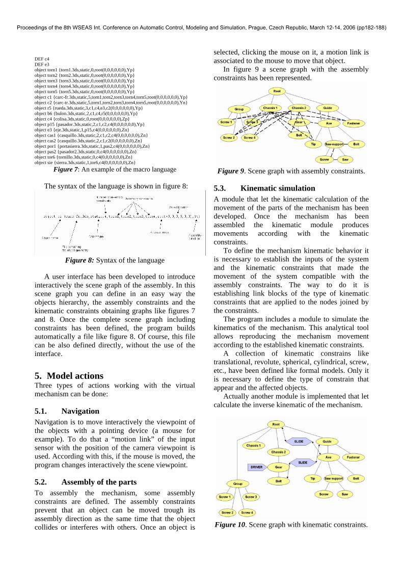
In figure 9 a scene graph with the assembly constraints has been represented.
Figure 9. Scene graph with assembly constraints.
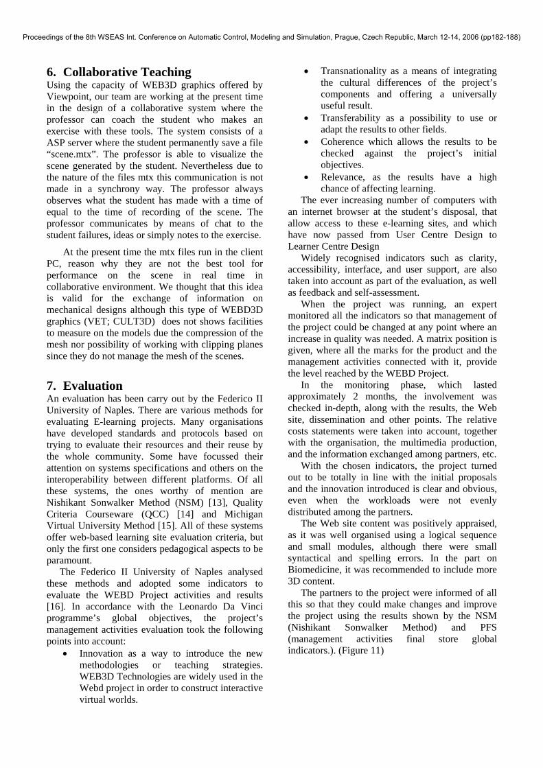
5.3. Kinematic simulation A module that let the kinematic calculation of the movement of the parts of the mechanism has been developed. Once the mechanism has been assembled the kinematic module produces movements according with the kinematic constraints.
To define the mechanism kinematic behavior it is necessary to establish the inputs of the system and the kinematic constraints that made the movement of the system compatible with the assembly constraints. The way to do it is establishing link blocks of the type of kinematic constraints that are applied to the nodes joined by the constraints.
The program includes a module to simulate the kinematics of the mechanism. This analytical tool allows reproducing the mechanism movement according to the established kinematic constraints.
A collection of kinematic constrains like translational, revolute, spherical, cylindrical, screw, etc., have been defined like formal models. Only it is necessary to define the type of constrain that appear and the affected objects.
Actually another module is implemented that let calculate the inverse kinematic of the mechanism.
Figure 10. Scene graph with kinematic constraints.
Proceedings of the 8th WSEAS Int. Conference on Automatic Control, Modeling and Simulation, Prague, Czech Republic, March 12-14, 2006 (pp182-188)
6. Collaborative Teaching Using the capacity of WEB3D graphics offered by Viewpoint, our team are working at the present time in the design of a collaborative system where the professor can coach the student who makes an exercise with these tools. The system consists of a ASP server where the student permanently save a file “scene.mtx”. The professor is able to visualize the scene generated by the student. Nevertheless due to the nature of the files mtx this communication is not made in a synchrony way. The professor always observes what the student has made with a time of equal to the time of recording of the scene. The professor communicates by means of chat to the student failures, ideas or simply notes to the exercise.
At the present time the mtx files run in the client PC, reason why they are not the best tool for performance on the scene in real time in collaborative environment. We thought that this idea is valid for the exchange of information on mechanical designs although this type of WEBD3D graphics (VET; CULT3D) does not shows facilities to measure on the models due the compression of the mesh nor possibility of working with clipping planes since they do not manage the mesh of the scenes.
7. Evaluation An evaluation has been carry out by the Federico II University of Naples. There are various methods for evaluating E-learning projects. Many organisations have developed standards and protocols based on trying to evaluate their resources and their reuse by the whole community. Some have focussed their attention on systems specifications and others on the interoperability between different platforms. Of all these systems, the ones worthy of mention are Nishikant Sonwalker Method (NSM) [13], Quality Criteria Courseware (QCC) [14] and Michigan Virtual University Method [15]. All of these systems offer web-based learning site evaluation criteria, but only the first one considers pedagogical aspects to be paramount.
The Federico II University of Naples analysed these methods and adopted some indicators to evaluate the WEBD Project activities and results [16]. In accordance with the Leonardo Da Vinci programme’s global objectives, the project’s management activities evaluation took the following points into account:
• Innovation as a way to introduce the new methodologies or teaching strategies. WEB3D Technologies are widely used in the Webd project in order to construct interactive virtual worlds.
• Transnationality as a means of integrating the cultural differences of the project’s components and offering a universally useful result.
• Transferability as a possibility to use or adapt the results to other fields.
• Coherence which allows the results to be checked against the project’s initial objectives.
• Relevance, as the results have a high chance of affecting learning.
The ever increasing number of computers with an internet browser at the student’s disposal, that allow access to these e-learning sites, and which have now passed from User Centre Design to Learner Centre Design
Widely recognised indicators such as clarity, accessibility, interface, and user support, are also taken into account as part of the evaluation, as well as feedback and self-assessment.
When the project was running, an expert monitored all the indicators so that management of the project could be changed at any point where an increase in quality was needed. A matrix position is given, where all the marks for the product and the management activities connected with it, provide the level reached by the WEBD Project.
In the monitoring phase, which lasted approximately 2 months, the involvement was checked in-depth, along with the results, the Web site, dissemination and other points. The relative costs statements were taken into account, together with the organisation, the multimedia production, and the information exchanged among partners, etc.
With the chosen indicators, the project turned out to be totally in line with the initial proposals and the innovation introduced is clear and obvious, even when the workloads were not evenly distributed among the partners.
The Web site content was positively appraised, as it was well organised using a logical sequence and small modules, although there were small syntactical and spelling errors. In the part on Biomedicine, it was recommended to include more 3D content.
The partners to the project were informed of all this so that they could make changes and improve the project using the results shown by the NSM (Nishikant Sonwalker Method) and PFS (management activities final store global indicators.). (Figure 11)
Proceedings of the 8th WSEAS Int. Conference on Automatic Control, Modeling and Simulation, Prague, Czech Republic, March 12-14, 2006 (pp182-188)

Figure 11: WEBD Project Evaluation Matrix .
8. Conclusion A virtual reality application has been presented.
This application allows the visualization and simulation of mechanical assemblies. This mechanism can be assembled or disassembled interactively using a mouse and a keyboard of a conventional computer.
A kinematic module has been also developed in order to simulate the movement of the mechanism.
In this project a set of learning modules of engineering of design through Internet has been developed where the three-dimensional and interactive graphics are the most innovating and attractive aspect. The last objective of the project is to demonstrate the benefit of the use of these technologies in education. WEB3D Technologies have been used to develop these models, providing them of a high degree of realism and interactivity. These technologies are characterized by a high level of realism and by a high rate of compression of image, which makes an optimum use in Internet. For this project more than 2,000 three-dimensional models have been developed. Nevertheless, the modelling work was laborious and slow and although these technologies have highest capacities, they are in a continuous improvement that sometimes causes confusion in its application.
To manage the courses a Website has been developed, including a control of the visits of the students exists and the access at the different levels from contents based on the self evaluation tests.
References [1] Tornincasa, S.;”Web3D Technology applications for distance training and learning: the Leonardo project WEBD”. XII International Conference on Design Tools and methods in industrial engineering. Rimini Sep. 2001 [2] Tornincasa, S.; “The Leonardo WEBD project: an example of the Web3D technology applications for distance training and learning”. XIV Congreso Internacional de Ingeniería Grafica INGEGRAF. Santander 2002. [3] Ed. Tittel (Editor), et al ,”Building Vrml Worlds”, 1996 [4] CosmoPlayer. http://www.cosmosoftware.com [5] Internet Railroad. http://member.aol.com/VRMLTrains/index_main. html [6] Technology High School Projects. Http://www.bergen.org/present/technologyhighschool/active/design_project.html [7] WebSET. http://www.sve.man.ac.uk.mvc/research/webset [8] “The Web3d repository” Http://www.vrml.org [9]Martínez Muneta, M. L.; Félez Mindán, J.; Romero Rey; G. “Ultimas tendencias en gráficos WEB3D para Internet”. XIV Congreso Internacional de Ingeniería Grafica INGEGRAF. Santander 2002. [10] Viewpoint: www.viewpoint.com [11] Cult3D: www.cult3d.com [12] Solid-works: www.solidworks.com [13] Nishikant Sonwalkar Method. Disien. http://www.uwex.edu/disted/desien/2002/0205/focus.htm. [14] Quality Criteria Courseware www.ecc.org.sg [15] Michigan Virtual University Course Evaluator http://standards.mivu.org/evaluator/ [16] Lanzotti, A.; Savarese, M.; “Quality evaluation of a learning and training project: The WEBD Project”. International Workshop in “New WEB technologies for collaborative design, learning and training” Turin. Nov. 2003
Proceedings of the 8th WSEAS Int. Conference on Automatic Control, Modeling and Simulation, Prague, Czech Republic, March 12-14, 2006 (pp182-188)