vii contrasting techniques from brightfield to plas-dic december 2008 rudi rottenfusser
TRANSCRIPT

VIIVII
Contrasting TechniquesFrom Brightfield to Plas-DIC
December 2008
Rudi Rottenfusser

C ONTRAST
50 – 0
/ 50 +
0 =
1
50 – 1
00 / 5
0 +
100 =
-0.3
3
50 – 5
0 / 5
0 +
50 =
0
Background of BrightnessSpecimen of Brightness
Background of Brightness-Specimen of Brightness
50 Units0 Units 100 Units
50 Units 50 50

Transmitted Light• Brightfield• Oblique
• Darkfield• Modulation, Varel Contrast• Phase Contrast• Polarized Light• DIC (Differential
Interference Contrast)• Fluorescence - not any
more > Epi !
Incident Light• Brightfield• Oblique
• Darkfield• Not applicable• Not any more (DIC !)• Polarized Light• DIC (Differential
Interference Contrast)• Fluorescence (Epi)
Illumination Techniques - Overview

Example

Brightfield
• For stained or naturally absorbing samples
• True Color Representation
• Proper Technique for Measurements
•Spectral
•Dimensional

Brightfield
Best Resolution when Condenser NA matches Objective NA!Minimum Contrast!
Objectivemin 2
λd
NA
Specimen
Objective
Condenser
Resolution (minimum resolved distance between 2 details):
dmind

Getting more contrast in the microscope:
“Dropping” the condenser
• No more separation of controls for field size and aperture angle
• Higher contrast, but at the cost of NA
• Scattered light enters the objective • Condenser not in proper position > spherical/chromatic aberrations
Bad Idea!

•Increases contrast
•Increases depth of field
•Reduces resolution
Getting more contrast in the microscope:
“Stopping down” the condenser (reducing the size of aperture diaphragm)
Objectivemin 2
λd
NA
CondenserObjectivemin
λd
NANA
Condenser Aperture matches Objective
Condenser Aperture stopped down

Effect of Aperture Diaphragm
NA Condenser = NA Objective

Paramecium bursaria
Condenser diaphragm open Condenser Diaphragm almost closed

Paramecium bursaria
Indian Ink Staining Feulgen Staining Silver Staining
Different Staining Techniques

Contrasting TechniquesGoing more into details
Brightfield• Oblique• Darkfield • Phase• Varel• Hoffman• Pol• DIC• Plas-DIC

Getting more contrast in the microscope:
Oblique Illumination(moving the aperture diaphragm sideways)
•Increases contrast
•Increases depth of field
•3-D effect
•Slightly reduces
resolution


Required conditions:
Illumination Aperture must be larger than objective aperture
I.e. direct light must bypass observer
Iris Diaphragm
Low NA Objectiv
e
High NA Objective
Darkfield

Darkfield
Highest contrast
Detection of sub-resolution details possible
No staining necessary
Central Darkfield via “hollow cone”
Oblique Darkfield via Illumination from the side
Excellent technique to detect traces of contaminants
Not useful for Measurements (sizes exaggerated)

Paramecium bursaria
Polarized LightDarkfield


Phase Contrast Phase Contrast (Frits (Frits
Zernike 1934)Zernike 1934)
- “Halo” effect > Reduced resolution
+ No staining necessary
+ Good Depth of Field
+ Easy alignment
+ Orientation independent
+ Repeatable setup
+ Works with plastic dishes
+ New positive / negative Phase
Contrast

Required Adjustment:Superimpose Phase Ring of condenser over (dark) phase plate of objective (after Koehler Illumination)
Required Components for Phase Contrast:
1. Objective with built-in Phase Annulus
2. Condenser or Slider with Centerable Phase Ring for illumination (Ph0, 1, 2 or 3)

Phase Shifts:
Cells have higher n than water. Light moves slower in higher n, consequently resulting in a phase retardation
Phase shift depends on n and on thickness of specimen detail
•Illumination bypasses Specimen > no phase shift
•Illumination passes through thin part of Specimen > small phase retardation
•Illumination passes through thick part of Specimen > larger phase retardation

Phase Plate
Objective
Specimen
Condenser
Condenser Phase Ring
520nmλ
Intermediate Image
Phase Contrast
Imaging Path
{
-2 -1 0 +1 +2
Diffraction Orders
Non-diffracted wave
Non-diffracted waveshifted by /4)
Diffracted waveshifted by /4)

1. Illumination from Condenser Phase Ring (“0” Order) > meets phase ring of objective
2. Objective Phase Ring a) attenuates the non-diffracted 0th Order b) shifts it ¼ wave forward
3. Affected rays from specimen, expressed by the higher diffraction orders, do not pass through phase ring of objective >¼ wave retarded
4. Non-diffracted and diffracted light are focused via tube lens into intermediate image and interfere with each other; ¼+¼= ½ wave shift causes destructive interference i.e. Specimen detail appears dark
Condenser
Objective
Specimen
Tube Lens
Sales Training Oct. 2006
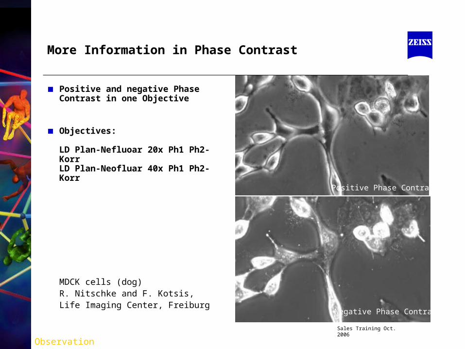
More Information in Phase Contrast
Positive and negative Phase Contrast in one Objective
Objectives:
LD Plan-Nefluoar 20x Ph1 Ph2- KorrLD Plan-Neofluar 40x Ph1 Ph2- Korr
MDCK cells (dog) R. Nitschke and F. Kotsis,Life Imaging Center, Freiburg
Positive Phase Contrast
Negative Phase Contrast
Observation

Paramecium bursaria
Phase ContrastCondenser diaphragm open
Brightfield

Rhipidodendron
Phase Contrast
Cochliopodium
Phase Contrast

Lyngbya Bacteria
Phase Contrast

Neurons
Thin Phase Object in plastic vessel
Varel Contrast

Varel Contrast (1996 - Zeiss) Varel Contrast (1996 - Zeiss)
For unstained (live) specimensFor unstained (live) specimensCombination of oblique illumination Combination of oblique illumination
and and attenuation of non-diffracted attenuation of non-diffracted lightlight
No “Halo”-effect as in Phase No “Halo”-effect as in Phase ContrastContrast
Complementary technique to Phase Complementary technique to Phase (easy switchover)(easy switchover)
Simulated 3-D image (similar to Simulated 3-D image (similar to DIC)DIC)
Less resolution than DICLess resolution than DICWorks with plastic dishesWorks with plastic dishes

Movable Ring Sector (Varel Ring)
Required Components for Varel:
1. Objective with Varel- and Ph ring
2. Slider or Condenser with specific Varel 1 or Varel 2 ring sector
Back Focal Plane of Varel / Phase
Objective
Brightfield / oblique
Darkfield “Varel”

Modulation Contrast (Hoffman) Modulation Contrast (Hoffman)
For unstained (live) specimensFor unstained (live) specimens Simulated 3-D image (similar to DIC)Simulated 3-D image (similar to DIC) No Halo-effect (as in Phase Contrast)No Halo-effect (as in Phase Contrast) Usable with plastic dishes Usable with plastic dishes Less resolution as DICLess resolution as DIC
Note: Modulation Contrast Objectives are not recommended for fluorescence; due to potential damage of modulator and uneven illumination

3% transmittance
Modulation ContrastModulation Contrast
Required Components for Modulation Contrast:
Specially Modified Objective (With Built-in Modulator)
Modified Condenser with off-axis slit (double slit with polarizer)

Polarized Light
One starts out usually by crossing two polarizers (polarizer and “analyzer”) in a microscope.
The specimen is located between them.
Only birefringent particles (e.g. crystals) become visible, when they are rotated via rotating stage.
Isotropic components will remain dark.
Polarized Light looks sometimes just like Darkfield because edges become visible due to “edge birefringence”.

Polarized Light
Birefringent Material
Polarizer
Analyzer

Polarized Light
Birefringent Material
Polarizer
Analyzer
Polarizer
Analyzer

Polarized Light
Birefringent Material
Polarizer
AnalyzerPolarizer
Analyzer

Polarized Light
Birefringent Material
Polarizer
Analyzer

Polarized Light
Birefringent Material
Polarizer
Analyzer

When Polarizers are crossed, only items that rotate the plane of polarization reach the detector.
Polarized Light
Polarizer 1
Polarizer 2
(Analyzer)
Specimen
Wave plate adds color

Brightfield
Background
Birefringent Material
Polarized Light Pol + Red I
Color of sample and
background modified by wave plate

Required / Recommended Components:
• Polarizer (fixed or rotatable)
• Analyzer (fixed or rotatable)
• Strain-free Condenser and Objective
• Rotating, centerable Stage
• Wave plate and/or Compensator
• Crossline Eyepiece

• The numerical difference between the maximum and minimum refractive indices of anisotropic substances. nγ - nα.
• Birefringence may be qualitatively expressed as • low (0 - 0.010), • moderate (0.010 – 0.050)• high (>0.050) • extreme (>0.2)
• Birefringence may be determined by use of compensators, or estimated through use of a Michel-Lévy Interference Color Chart.
Birefringence
dn Path Optical
dnndndn boBackgroundObject Difference Path Optical

•An excellent introduction to this chart is provided at McCrone’s website http://www.modernmicroscopy.com/main.asp?article=15
LOW
< 0.010Moderate
0.010 – 0.050
High
> 0.050

3rd
OrderRed
1st OrderRed
1st OrderRed
2nd OrderRed
2nd
OrderRed
3rd
OrderRed

50
40
30
20
10
0
1800170016001500140013001200110010009008007006005004003002001000
Retardation (nm)
I/I o
alpha gamma
1st Order Red Plate550 nm Retardation
Sensitive Tint
Field ofView

Orthoscopy / Conoscopy
• Analyzing minerals is based on such morphological and optical features as form, cracks, color, pleochroisms, and their characteristic interference colors.
• Orthoscopy and conoscopy are the most important techniques in classical transmitted light polarization microscopy. With their different ways of examining, they provide different options, e.g. in mineral diagnosis in geological microscopy.
• In orthoscopy, each pixel corresponds to a dot in the specimen.
• In conoscopy, each pixel corresponds to a direction in the specimen. This technique requires the use of the highest objective and condenser aperture possible.
• Conoscopy is used when additional information about the specimen is necessary for analysis. It provides interference images that can be seen through the eyepiece and enables differentiation according to 1 or 2 axes and with compensator λ (λ-lamda, Red I), according to 1-axis positive/negative or 2-axis positive/ negative.
• A Bertrand lens in the light path makes visible the interference or axial image in the back focal plane of the specimen.

Some Types of Birefringence
• Intrinsic or crystalline (Quartz, Calcite, Myosin Filaments, Chromosomes, Keratin, Cellulose Fibers)
• Form or Textural (Plasma membranes, Actin filaments, microtubules)
• Edge (resulting from diffraction at edges of objects embedded in a medium of different refractive Index)
• Strain (resulting from mechanical stress e.g. glass, plastic sheets)
• Circular –also known as- Optical Rotation (sugars, amino acids, proteins)

The wave exhibits electric (E) and magnetic (B) fields whose amplitudes oscillate as a sine function over dimensions of space or time. The amplitudes of the electric and magnetic components at a particular instant or location are described as vectors that vibrate in two planes perpendicular to each other and perpendicular to the direction of propagation. At any given time or distance the E and B vectors are equal in phase. For convenience it is common to show only the electric field vector (E vector) of a wave in graphs and diagrams.
Light as an electromagnetic wave

E
y
xz
Ey
Ex
E E
Polarized Light
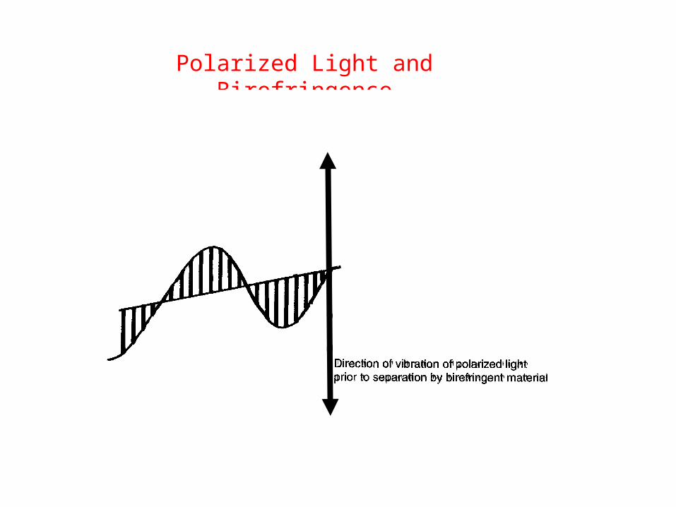
Polarized Light and Birefringence

Polarized Light and Birefringence
Interface with birefringent Material
n = higher refractive index > slower waven = lower refractive index > faster wave
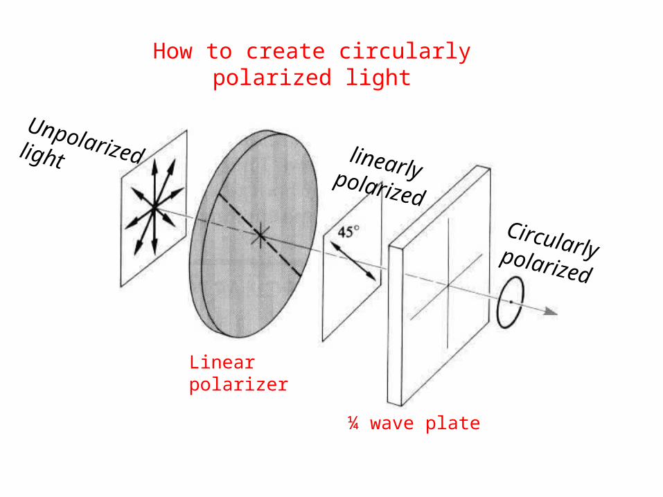
Linearpolarizer
¼ wave plate
Unpolarizedlight linearlypolarized
Circularlypolarized
How to create circularly polarized light

xz
Ex
E
Circularly Polarized Light
1
1
2
2
3
3
4
4
5
5
E

y
xz
Ey E
x
E E
Sénarmont Compensator*
¼ wave plate, located before analyzer, is oriented with its birefringence parallel to the polarizer or analyzer. Therefore, there will be no effect on the polarized beam.
Birefringence produced by specimen (occurring at 45˚), will be converted by ¼ wave plate into circular polarized light which can pass through the analyzer.
By rotating the analyzer, it is possible to introduce “bias” birefringence because it will not be parallel to ¼ wave plate any more. * 1st described by de Sénarmont in 1840


9 Image
8 Tube lens7 Analyzer 7a Wave Plate)
6 Wollaston Prism Slider5 Objective
4 Specimen
3 Condenser 2 Wollaston Prism
1 Polarizer
DIC Principle DIC Principle (F.H.Smith, 1952)(F.H.Smith, 1952)

DIC DIC (Nomarski/Allen 1969)(Nomarski/Allen 1969)
Differential Interference ContrastDifferential Interference Contrast
Changes GRADIENTS into brightness differencesChanges GRADIENTS into brightness differences
Eye-pleasing 3-D Image appearanceEye-pleasing 3-D Image appearance
High Contrast and high resolutionHigh Contrast and high resolution
Control of condenser aperture for optimum contrastControl of condenser aperture for optimum contrast
Great for “optical sectioning” due to small depth of fieldGreat for “optical sectioning” due to small depth of field
Color DIC by adding a wave plateColor DIC by adding a wave plate
Best contrast / resolution via different DIC slidersBest contrast / resolution via different DIC sliders
Orientation-specific > orient fine details perpendicular to DIC Orientation-specific > orient fine details perpendicular to DIC prismprism
Requires strain-free elements, not for birefringent specimensRequires strain-free elements, not for birefringent specimens

y
xz
Ey
Ex
E E
Wollaston Prism
Polarized beam, under 45˚ to prism, gets split into “ordinary” and “extraordinary” beam
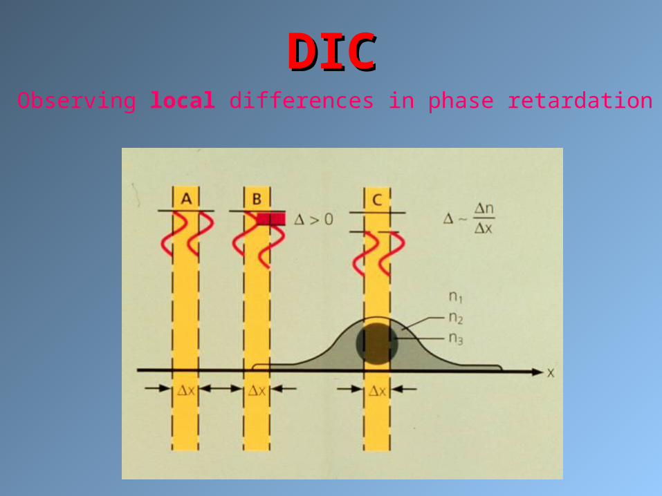
DICDICObserving local differences in phase retardation

IR-DIC IR-DIC
IR increases depth of field – useful for thick IR increases depth of field – useful for thick tissues tissues
Achieve Contrast in Electrophysiology Achieve Contrast in Electrophysiology applicationsapplications
Special Objective and Polarizer recommendedSpecial Objective and Polarizer recommended
Requires IR filter for transmitted light Requires IR filter for transmitted light
For heat protection, special filter combinationFor heat protection, special filter combination

-20.00
0.00
20.00
40.00
60.00
80.00
100.00
-20.00
0.00
20.00
40.00
60.00
80.00
100.00
RG 9
Calf lex
Special Filter Arrangement Special Filter Arrangement for IR-DIC for IR-DIC
RG 9 = IR Filter
Calflex = Heat reflecting filter

62
PlasDIC PlasDIC Rainer Danz, 2004 (patented 2006)
Most important before injection: sharp image of
zona pellucida,
tip of injection pipette
and oolemma
-1 0 +1
-1 0 +1
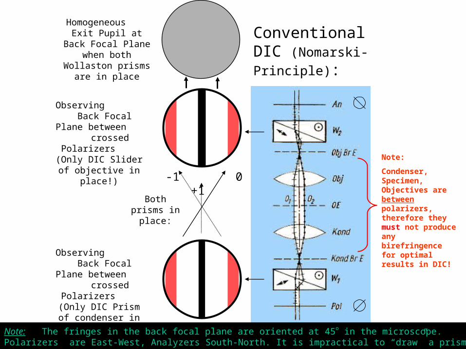
Conventional DIC (Nomarski-Principle):
Note:
Condenser, Specimen, Objectives are between polarizers, therefore they must not produce any birefringence for optimal results in DIC!
Observing Back Focal Plane
between crossed Polarizers (Only DIC Prism of condenser in
place!)
Observing Back Focal Plane
between crossed Polarizers (Only DIC Slider
of objective in place!)
Homogeneous Exit Pupil at Back Focal Plane when both Wollaston
prisms are in place
Both prisms in
place:
Note: The fringes in the back focal plane are oriented at 45o in the microscope. Polarizers are East-West, Analyzers South-North. It is impractical to “draw” a prism cross-section under 45o to the drawing surface…

BFP Objective.
Analyzer
Objective
Condenser
Conventional DIC
Slit
Observing Back Focal Plane between crossed Polarizers:
Françon-Yamamot
o
Polarizer
-1 0 +1
Note: The fringes in the back focal plane are actually oriented at 45o in the microscope. Polarizers are East-West, Analyzers South-North. This display takes into account that it is impractical to “draw” a prism cross-section under 45o to the drawing surface…

BFP Objective.
Analyzer
Objective
Condenser
Conventional DIC
Slit
ZEISS Plas-DIC
Polarizer
-1 0 +1
Observing Back Focal Plane between crossed Polarizers:
Note: The fringes in the back focal plane are actually oriented at 45o in the microscope. Polarizers are East-West, Analyzers South-North. This display takes into account that it is impractical to “draw” a prism cross-section under 45o to the drawing surface…

-0.25
0
0.25
0.5
0.75
1
0 1/4 1/2 3/4 1
/4 Optimal Condition !
Contrast = f (Slit Width) sinc
Slit Width as it is projected into Back Focal Plane (BFP) of Objective
Sinc Function
Distance between 0 and 1st order of birefringence
Contr
ast

Required Components for Plas DIC
2) Slit diaphragm PlasDIC for condenser or slider
1) Nosepiece with receptacles for DIC sliders (AxioObserver or Axiovert 40 CFL)
3) Objective for available Plas-DIC Sliders
4) The right PlasDIC slider for each objective
5) Fixed Analyzer Slider or Analyzer in Cube
Note: PlasDIC and Analyzer sliders should be removed during fluorescence imaging. They will reduce the intensity substantially if left in place!

68
PlasDIC - Advantages
High optical resolution, close to regular DIC, at least equal to *Hoffmann Modulation contrast
Excellent relief and three dimensional impression, large depth of field, great for work with manipulators and multiple probes
Cost effective (no special objectives, no special condensor, no second prism)
Plastic dishes, Ph objectives, birefringent specimens have no effect on image quality
Very simple handling: no centering or change of diaphragm
Easily upgradable: takes customers budget into account
*Hoffmann Modulation contrast: Also very good contrast, but most users don´t know how to optimize the settings, which are much more complicated to establish.
The first polarization-optical interference contrast designed for plastic vessels
Patent No. DE 10219804

69
Comparison of Contrast Methods
Phase VAREL
Hoffmann
PlasDIC
DIC
Contrast thick specimen
_ _ + + + ++
Contrast thin specimen
++ - + + +
Resolution + _ _ + + ++
Optical Sectioning capability
_ _ _ + + ++
Depth of focus in living cells
_ _ + + ++ +
Homogenity field of view
++ _ + + +
Reproducibility of setting
_ _ _ + +
Plastic Vessels + + (+) ++ _
Price