view project status & reports -...
TRANSCRIPT

1 30-JUN-2010 ISSUED FOR IMPLEMENTATION DB AA SRP
0 30-MAR-2009 ISSUED FOR IMPLEMENTATION DB AA SRP
Rev. No Date Purpose Prepared by Reviewed by
Approved by
Format No. 5-2000-0600-F8 Rev. 1 Copyrights EIL – All rights reserved
Document No. 7221-0441-UM-2402
Rev. No. 1 Page 1 of 38
User Manual
PCAMS
(Pre Commissioning and Commissioning Activities
Management System) Ver 2.0
VIEW PROJECT STATUS & REPORTS

Format No. 5-2000-0600-F8 Rev. 1 Copyrights EIL – All rights reserved
Document No. 7221-0441-UM-2402
Rev. No. 1 Page 2 of 38
User Manual
Contents
INTRODUCTION .......................................................................................................................... 3
REPORTS ..................................................................................................................................... 4
BRIEF SYSTEM DETAILS ......................................................................................................... 6
OPERATING DETAILS ............................................................................................................... 6
LOGIN SCREEN .......................................................................................................................... 7
VIEW PROJECT STATUS AND REPORTS ......................................................................... 10
VIEW PROJECT STATUS AND REPORTS>>LIST OF UNITS ............................................................ 11 VIEW PROJECT STATUS AND REPORTS>>SYSTEM DOSSIER INDEX (SYSTEM WISE) ................... 11 VIEW PROJECT STATUS AND REPORTS >>VIEW PROCESS / ENGINEERING DOCUMENTS ............ 13 VIEW PROJECT STATUS AND REPORTS >>CURRENT PROJECT STATUS OF SYSTEM DOSSIER ..... 17 VIEW PROJECT STATUS AND REPORTS >>FORMAT STATUS ....................................................... 19 VIEW PROJECT STATUS AND REPORTS >>ISSUED FORMATS REPORTS (I-V) ............................. 22 VIEW PROJECT STATUS AND REPORTS >>CURRENT FLUSHING STATUS .................................... 23 VIEW PROJECT STATUS AND REPORTS >>COMMISSIONING PROJECT TEAM............................... 24 VIEW PROJECT STATUS AND REPORTS >>JOB QUALITY PLAN ................................................... 25 VIEW PROJECT STATUS AND REPORTS >>SYSTEM DEFINITION.................................................. 26 VIEW PROJECT STATUS AND REPORTS >>SYSTEM TAG NUMBER DETAILS................................ 27 VIEW PROJECT STATUS AND REPORTS >>EQUIPMENTS / INSTRUMENTS CODIFICATION ............ 28 VIEW PROJECT STATUS AND REPORTS >>MECHANICAL CHECKLIST ......................................... 29 VIEW PROJECT STATUS AND REPORTS >>MECHANICAL CHECKLIST RESPONSIBILITIES ............ 32 VIEW PROJECT STATUS AND REPORTS >>PRECOMMISSIONING CHECKLIST .............................. 33 VIEW PROJECT STATUS AND REPORTS >>VIEW DESIGN DATA OF CRITICAL EQUIPMENT .......... 34

Format No. 5-2000-0600-F8 Rev. 1 Copyrights EIL – All rights reserved
Document No. 7221-0441-UM-2402
Rev. No. 1 Page 3 of 38
User Manual
Introduction Based on the requirements defined by POSD (Plant Operation and Safety Department), PCAMS software system has been developed by ITS team to provide the online facilities for doing site co-ordination activities for smooth and safe pre commissioning and commissioning of plants. At present this software is being used by the interdisciplinary team consisting of Construction, Project, PDD, POSD, Client, PMC and other Engineering department for GGSR project (Job no 6922) with the following URL http://pcams.eil.co.in.
Earlier there was manual system to maintain data and the project teams used to enter and store pre-commissioning related data in excel sheets and word documents. There was no centralized system to maintain the consistency of information for activities carried out at HO and site office.
With the usage of PCAMS software, it caters the need of EIL and Client through a systematic array of process / engineering documents uploaded over a web server so that the same can be retrieved by a SCT /Construction /Project and Client team during process plant’s pre commissioning and commissioning activities at site and HO. It will act as an interface between SCT, Construction and Client team members.
Because of Web based environment, it facilitates integrated approach to data capture, maintenance, storage, sharing and usage of centralized database among the authorized personnel within and outside the department. It is well structured and has provision to accommodate all different kind of jobs. It acts as an interface between SCT / Construction / Project and Client. All the users have online access to view projects data which is currently available and simultaneously are able to upload files and print reports as required during the process. The Project / Construction / Client and PMC will get the current project status along with all the documents which are relevant to pre-commissioning of plant. The entire project team has the facility to view or generate multiple reports as per project requirement such as
• System dossier details • Mechanical and pre commissioning Checklist, Equipment list (overall or system wise) • Line list (overall or system wise) • Instrument Index (overall or P&ID wise or system wise) • P&ID index • Equipment / Instruments Datasheet • Characteristics / Heat curve • System mark-up P&ID • Current Format Status • Current Project Status • Equipment summary • Flushing schemes • Issued Format (I-V) reports
It also provides the Overall track record of progress of pre-commissioning and commissioning activities in the form of FORMAT-I, FORMAT-II, FORMAT-III, FORMAT-IV AND FORMAT-IV reports. During the pre-commissioning of systems at site, Client gets the auto e-mail from construction and POSD regarding the liquidation of checklist with current status.

Format No. 5-2000-0600-F8 Rev. 1 Copyrights EIL – All rights reserved
Document No. 7221-0441-UM-2402
Rev. No. 1 Page 4 of 38
User Manual
Reports
o Unit Details
o List of System Identification
o List of Equipment with codification
o List of Mechanical Checklist with assigned responsibility
o List of Pre-commissioning Checklist
o Pre-commissioning Activities
o List of Clients / PMC / Licensors
o List Project Commissioning Team (unit wise)
o List of System Tag no’s with details
o System Dossier Index
• Complete
• For Specific components like Instruments , Equipments, PIDs,
o Process / Engineering Documents like
• Instrument Index
• Unit wise (Complete index)
• System Wise
• PID wise
• Equipment List
• Unit wise (Complete index)
• System Wise
• Line Schedule
• Unit wise (Complete index)
• System Wise
• PID Index
• Unit wise (Complete index)
• System Wise
• Equipment Data sheet
• Instrument Data Sheet
• PID’s
• Characteristics curves datasheet for rotating equipments
o Current Project Status of System Dossier
• Unit wise
• Project wise (for all the units)
o Current Format Status for
• Issued System
• As on Systems

Format No. 5-2000-0600-F8 Rev. 1 Copyrights EIL – All rights reserved
Document No. 7221-0441-UM-2402
Rev. No. 1 Page 5 of 38
User Manual
• Pending System
o Formats Reports
o Format I
• Acceptance Report (Intimation of completion of construction)
• List of Attachment
o Format II
• Issued Report (For the systems offered by Construction)
• Client Punch list
• Consolidated Punch points
• Client Punch list History
• Email History
o Format III
• Acceptance Report (Intimations of liquidation of checklist points)
• List of Attachment
• Balance Punch list
• Construction Remarks
• Email History
o Format IV
• Acceptance Report (Completion of flushing/blowing/ boxing up)
• List of Attachment
• Compliance Sheet
• Complete Remarks List
• SCT Remarks
• Email History
o Format V
• Issued by SCT
• Acceptance Report (Completion of PLANT)
• Email History
o Current Flushing Status
o Job Quality Plan
o Design Parameters for Critical Equipments / Instruments
• Pump
• Column
• Heat Exchanger
• Heaters
• Compressor
• Turbine

Format No. 5-2000-0600-F8 Rev. 1 Copyrights EIL – All rights reserved
Document No. 7221-0441-UM-2402
Rev. No. 1 Page 6 of 38
User Manual
• Control Valve
o List of reference documents (unit wise) required during pre-commissioning which are being uploaded by group leader.
Brief System Details The aim of developing the software is to channelize the link and data flow during pre-commissioning and commissioning in a more structured way. The software will be nested on a web browser allowing the access for any location with an internet/lease line facility. The various processes and inter-process data flow in this system has been indicated in the figure below:
Operating Details The software can be used by accessing the server by giving the URL : http://pcams.eil.co.in. in the internet explorer. The first screen displayed is the Login Screen. The pages ahead explain the basic usage of this software.

Format No. 5-2000-0600-F8 Rev. 1 Copyrights EIL – All rights reserved
Document No. 7221-0441-UM-2402
Rev. No. 1 Page 7 of 38
User Manual
Login Screen As shown in figure below, the user can start using the software by giving his username and password in the login screen and clicking on the “Login” pushbutton. The login passwords and access to various subsequent modules are available based on the role levels that are being explained below.
The System can be accessed by only those users, who are the authorized commissioning team members of the existing jobs in the system. Once the user has logged in, it will check, whether he/she is EIL employee or NON EIL employee. If he is EIL employee then it checks among the authorized commissioning team members defined in the existing jobs. If found then it checks for the password as defined in the timesheet software. If the password matches then the system allows the user to proceed further otherwise it prompts as the unauthorized user and is disallowed to proceed further. If he/she is NON-EIL members (PMC / CLIENT / LICENSOR’S USER) but the authorized commissioning team member of the project, then he checks the user id and password as defined by the project co-coordinator. During login, all the users are assigned levels. According to this level, the rights are given to user, according to which menu items are enabled & disabled. At present five roles has been defined in the PCAMS software as defined below 1. Super user : System Coordinators (includes ITS Coordinator and POSD Coordinator
Irrespective of project) (One employee from the POSD department and one employee from the ITS Department)

Format No. 5-2000-0600-F8 Rev. 1 Copyrights EIL – All rights reserved
Document No. 7221-0441-UM-2402
Rev. No. 1 Page 8 of 38
User Manual
Full access has been provided in the admin module for all the projects and units and have rights to do the following activities
• Create Project / create Unit / create areas • Copy Project / Unit specific default data (library) from one unit to another unit
from the selected project. • Create / Update Clients / Licensor / PMS’s user ID. • Create / Update Commissioning Team • Create / Update Job Quality Plan (can change the performer and approver
level) • Create new commissioning code (department /division wise)
2. Project coordinator: (only one team member from project department )
Having partial access in the admin module for the selected unit and project and can do the following activities.
• Create / Update Commissioning Team (for the selected unit only) • Create / Update Job Quality Plan (can change the performer and approver
level)
3. Construction / Area coordinator: (EIL Construction Commissioning In-charge)
(Only one employee from the EIL construction site and do not have any access in the admin module)
4. Lead engineer :
(Multiple lead engineer are allowed and do not have any access in the admin module) 5. Job engineer :
(Multiple job engineer are allowed and do not have any access in the admin module)
(Separate facility has been provided to the Client is for updating their email ID and password as per their requirement.)

Format No. 5-2000-0600-F8 Rev. 1 Copyrights EIL – All rights reserved
Document No. 7221-0441-UM-2402
Rev. No. 1 Page 9 of 38
User Manual
Format No. 5-2000-0600-F8 Rev. 1 Copyrights EIL – All rights reserved
Document No. 7221-0441-UM-2402
Rev. No. 1 Page 10 of 38
User Manual
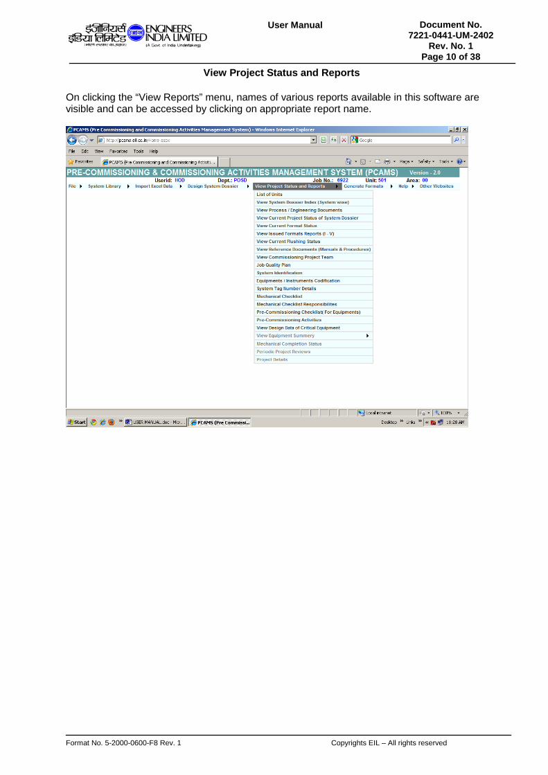
View Project Status and Reports On clicking the “View Reports” menu, names of various reports available in this software are visible and can be accessed by clicking on appropriate report name.

Format No. 5-2000-0600-F8 Rev. 1 Copyrights EIL – All rights reserved
Document No. 7221-0441-UM-2402
Rev. No. 1 Page 11 of 38
User Manual
View Project Status and Reports>>List of Units
This is the second sub menu item of ‘View Project Status and Reports’ menu. On clicking this item, a report will be generated of the units attached with the project.
View Project Status and Reports>>System Dossier Index (System wise)
This is the second sub menu item of ‘View Project Status and Reports’ menu. The user can select a system tag number from the dropdown, the system description of which will appear automatically. Then the user can generate any type of report, (PFD, PID, Line, Instruments, Equipments, Flushing Loops, Chemical Loops or Complete) by selecting the checkbox.

Format No. 5-2000-0600-F8 Rev. 1 Copyrights EIL – All rights reserved
Document No. 7221-0441-UM-2402
Rev. No. 1 Page 12 of 38
User Manual

Format No. 5-2000-0600-F8 Rev. 1 Copyrights EIL – All rights reserved
Document No. 7221-0441-UM-2402
Rev. No. 1 Page 13 of 38
User Manual
(Complete report) View Project Status and Reports >>View Process / Engineering Documents
On clicking ‘View Process / Engineering Documents’, the user can view/print all the engineering reports and datasheets.
The user needs to select a radiobutton first. If the user chooses one of the radiobuttons from PFD Index, PID Index, Line List, Instrument Index, Equipment List and Flushing Loop Index, then the radiobuttons with that particular choice will be enabled. The user can choose any one of the options. For example, as shown in the figure below, if the user chooses Line List

Format No. 5-2000-0600-F8 Rev. 1 Copyrights EIL – All rights reserved
Document No. 7221-0441-UM-2402
Rev. No. 1 Page 14 of 38
User Manual
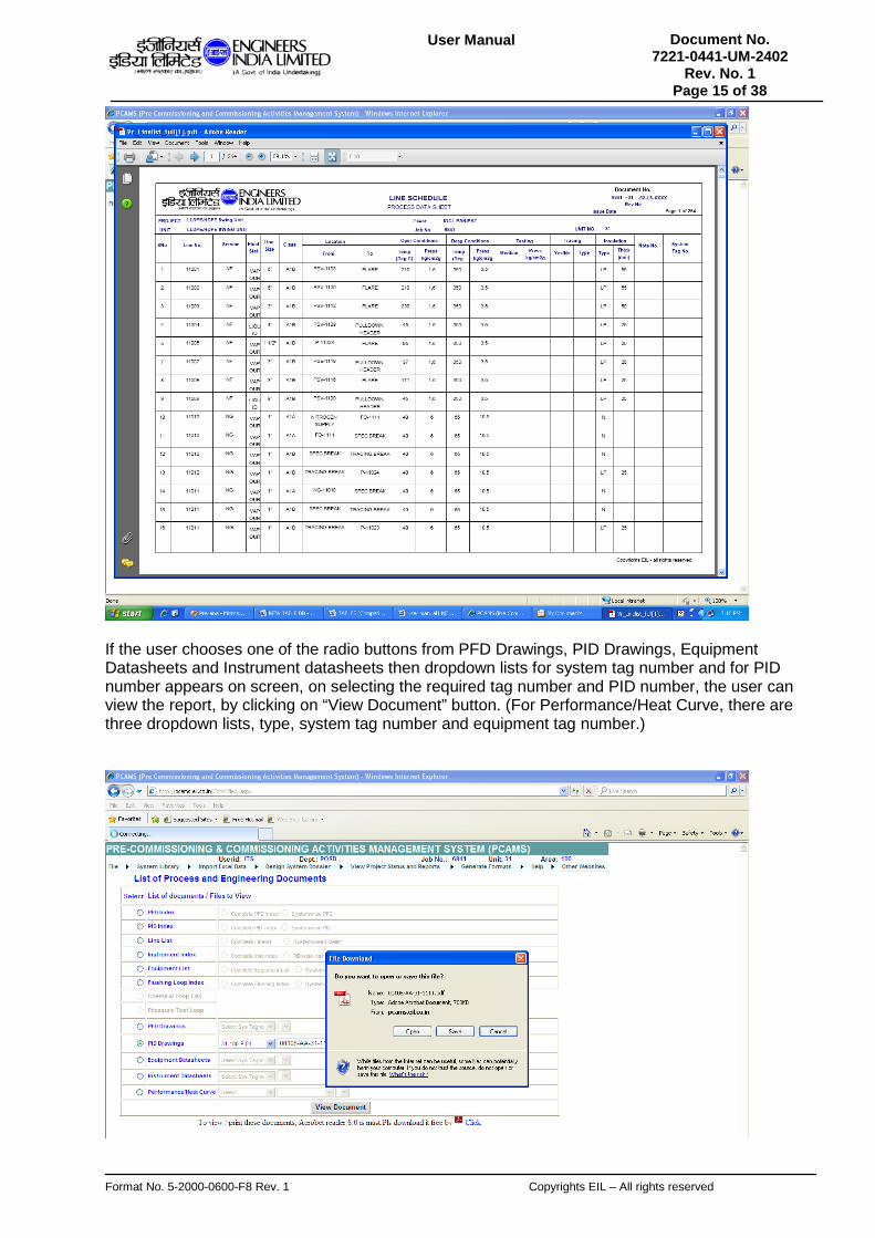
radiobutton, then he can choose either Complete Linelist or System wise linelist. If the user chooses complete linelist, then the View Document button will be enabled, and on clicking the button he can view the report. Otherwise, if he chooses systemwise linelist, then a dropdown list of all the system tag numbers appears on screen, from which user can select the system tag number, that is required. For Instrument Index, there are three options, complete Inst Index, PID wise Inst and System wise. Dropdown lists are attached with PID wise Inst and System wise Inst radio button.
Then on clicking “View Document” button, the systemwise linelist report will be generated for that particular system tag number.
Format No. 5-2000-0600-F8 Rev. 1 Copyrights EIL – All rights reserved
Document No. 7221-0441-UM-2402
Rev. No. 1 Page 15 of 38
User Manual
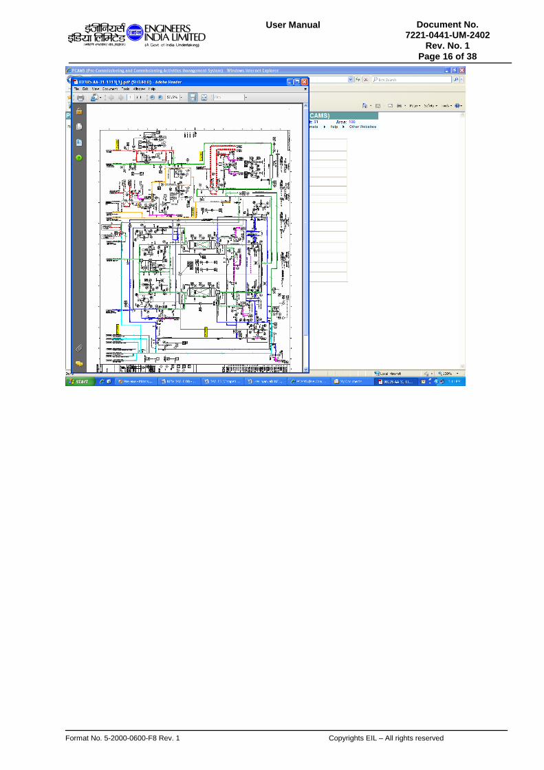
If the user chooses one of the radio buttons from PFD Drawings, PID Drawings, Equipment Datasheets and Instrument datasheets then dropdown lists for system tag number and for PID number appears on screen, on selecting the required tag number and PID number, the user can view the report, by clicking on “View Document” button. (For Performance/Heat Curve, there are three dropdown lists, type, system tag number and equipment tag number.)
Format No. 5-2000-0600-F8 Rev. 1 Copyrights EIL – All rights reserved
Document No. 7221-0441-UM-2402
Rev. No. 1 Page 16 of 38
User Manual
Format No. 5-2000-0600-F8 Rev. 1 Copyrights EIL – All rights reserved
Document No. 7221-0441-UM-2402
Rev. No. 1 Page 17 of 38
User Manual
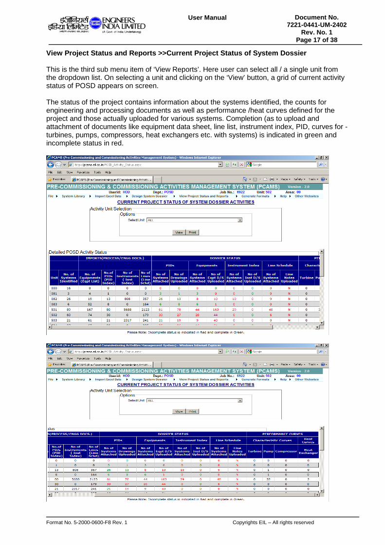
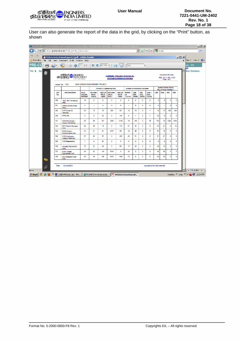
View Project Status and Reports >>Current Project Status of System Dossier
This is the third sub menu item of ‘View Reports’. Here user can select all / a single unit from the dropdown list. On selecting a unit and clicking on the ‘View’ button, a grid of current activity status of POSD appears on screen. The status of the project contains information about the systems identified, the counts for engineering and processing documents as well as performance /heat curves defined for the project and those actually uploaded for various systems. Completion (as to upload and attachment of documents like equipment data sheet, line list, instrument index, PID, curves for - turbines, pumps, compressors, heat exchangers etc. with systems) is indicated in green and incomplete status in red.
Format No. 5-2000-0600-F8 Rev. 1 Copyrights EIL – All rights reserved
Document No. 7221-0441-UM-2402
Rev. No. 1 Page 18 of 38
User Manual
User can also generate the report of the data in the grid, by clicking on the “Print” button, as shown

Format No. 5-2000-0600-F8 Rev. 1 Copyrights EIL – All rights reserved
Document No. 7221-0441-UM-2402
Rev. No. 1 Page 19 of 38
User Manual
View Project Status and Reports >>Format Status
User can click on “Format Status” to get the job wise summary of formats for different units/area nos. Two grids appear on-screen, grid on the left side shows the number of systems, and their status (both total and pending), whereas grid on the right side, shows the formats issued breakup. User can select the unit number, area number and system tag number from the appropriate dropdown lists and also can select the status of the system. The user also has the option of viewing data for ‘all’ (unit numbers or area numbers or system tag numbers). Then the user will have to click on the “View” button. A new grid then appears on screen, which shows the details of the system’s status.

Format No. 5-2000-0600-F8 Rev. 1 Copyrights EIL – All rights reserved
Document No. 7221-0441-UM-2402
Rev. No. 1 Page 20 of 38
User Manual
The Issued status option gives dates as to when different formats were issued for different system(s) in a unit/area. All formats from I to V including revisions A and B are listed against each system and their corresponding issue dates are mentioned for them. Print out of this information can be obtained by clicking the Print button.
The ‘As on Status’ gives the current format status for all the systems. It conveys when a particular format was issued, its status (accepted/rejected) and reason for acceptance/rejection. As in the case of issued status, report can be printed for this option as well.

Format No. 5-2000-0600-F8 Rev. 1 Copyrights EIL – All rights reserved
Document No. 7221-0441-UM-2402
Rev. No. 1 Page 21 of 38
User Manual
The ‘Pending Status’ gives the pending format status for all the systems. It gives a list of all systems for which no format has been issued so far. . As in the case of issued status, report can be printed for this option as well.

Format No. 5-2000-0600-F8 Rev. 1 Copyrights EIL – All rights reserved
Document No. 7221-0441-UM-2402
Rev. No. 1 Page 22 of 38
User Manual
View Project Status and Reports >>Issued Formats Reports (I-V)
Here user can view the reports (format wise), for the issued systems. User can select a radio button from the five choices for different formats.

Format No. 5-2000-0600-F8 Rev. 1 Copyrights EIL – All rights reserved
Document No. 7221-0441-UM-2402
Rev. No. 1 Page 23 of 38
User Manual
Once the user selects a radio button, the radio buttons attached with it are enabled. The user can then select one of the choices, then he needs to select a system tag number, when user selects a system tag number, its issued dates appear on the dropdown list, user can select the appropriate choice and then he needs to click on the ‘View Reports’ button. The report of that particular issued system will be generated.
View Project Status and Reports >>Current Flushing Status
On clicking “Current Flushing Status” in “View Project Status and Reports” menu, user can have access to the summary of flushing loop status. User has the option to view the summary status wise. User can view the detailed summary of ‘pending’, ‘completed’, ‘under process’ or ‘all’ status, by selecting status from dropdown list and clicking “View” button.
Also user can generate report by the click of “Print” button.

Format No. 5-2000-0600-F8 Rev. 1 Copyrights EIL – All rights reserved
Document No. 7221-0441-UM-2402
Rev. No. 1 Page 24 of 38
User Manual
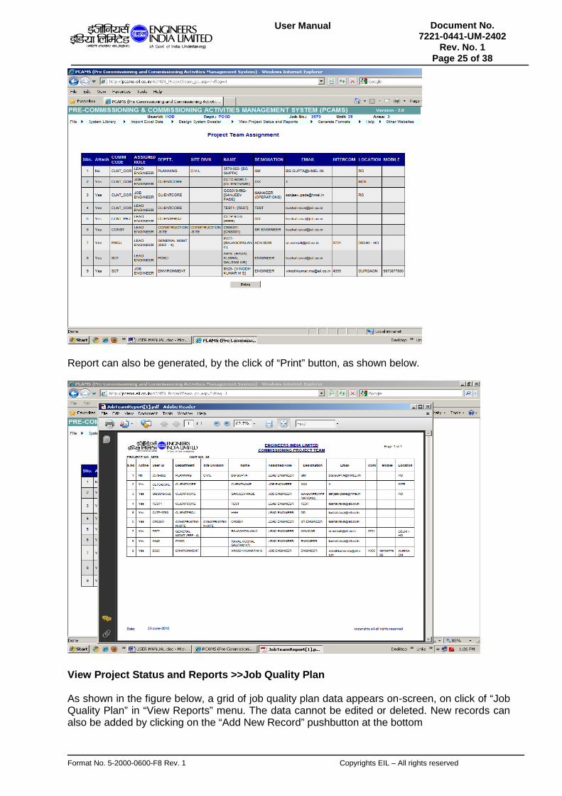
View Project Status and Reports >>Commissioning Project Team
On clicking this submenu item, a grid appears on-screen, which shows the project team assignment. This grid gives all the details (Code,Name, Role, Department, Designation, Intercom, Location, Mobile, Site/Divn, attached/detached status and E-mail ID) of the persons attached with the project.
Format No. 5-2000-0600-F8 Rev. 1 Copyrights EIL – All rights reserved
Document No. 7221-0441-UM-2402
Rev. No. 1 Page 25 of 38
User Manual
Report can also be generated, by the click of “Print” button, as shown below.
View Project Status and Reports >>Job Quality Plan
As shown in the figure below, a grid of job quality plan data appears on-screen, on click of “Job Quality Plan” in “View Reports” menu. The data cannot be edited or deleted. New records can also be added by clicking on the “Add New Record” pushbutton at the bottom

Format No. 5-2000-0600-F8 Rev. 1 Copyrights EIL – All rights reserved
Document No. 7221-0441-UM-2402
Rev. No. 1 Page 26 of 38
User Manual
. User can also generate the report, by clicking on the “PRINT” button.
View Project Status and Reports >>System Definition
On click of “System Definition”, a grid appears on-screen, which shows all the systems (within the unit) and their description.

Format No. 5-2000-0600-F8 Rev. 1 Copyrights EIL – All rights reserved
Document No. 7221-0441-UM-2402
Rev. No. 1 Page 27 of 38
User Manual
Reports can also be generated on click of “PRINT” button, as shown below.
View Project Status and Reports >>System Tag Number Details
On clicking this, a grid appears, which shows all the details of system tag numbers, including, system description and system image and indicates whether the system is attached with Equipment, Instrument, PID, PFD and Line List.

Format No. 5-2000-0600-F8 Rev. 1 Copyrights EIL – All rights reserved
Document No. 7221-0441-UM-2402
Rev. No. 1 Page 28 of 38
User Manual
Report can also be generated, by pressing “PRINT” button.
View Project Status and Reports >>Equipments / Instruments Codification
Here the user can select one of the subsystem types from the dropdown list.

Format No. 5-2000-0600-F8 Rev. 1 Copyrights EIL – All rights reserved
Document No. 7221-0441-UM-2402
Rev. No. 1 Page 29 of 38
User Manual
After selecting the subsystem type, a grid showing the subsystem code and subsystem description appears on-screen. The user can generate the report by clicking on “PRINT” button, as shown below.
View Project Status and Reports >>Mechanical Checklist
On clicking “Mechanical Checklist” submenu item, two dropdown lists of Subsystem type and Subsystem Description appear on-screen. The user can select any type and description from the dropdowns.

Format No. 5-2000-0600-F8 Rev. 1 Copyrights EIL – All rights reserved
Document No. 7221-0441-UM-2402
Rev. No. 1 Page 30 of 38
User Manual
After selecting the type and description, if data exists within that subsystem, then it will appear inside a grid, as shown in the figure below.
Reports can also be generated by clicking “PRINT” button.

Format No. 5-2000-0600-F8 Rev. 1 Copyrights EIL – All rights reserved
Document No. 7221-0441-UM-2402
Rev. No. 1 Page 31 of 38
User Manual

Format No. 5-2000-0600-F8 Rev. 1 Copyrights EIL – All rights reserved
Document No. 7221-0441-UM-2402
Rev. No. 1 Page 32 of 38
User Manual
View Project Status and Reports >>Mechanical Checklist Responsibilities
On clicking “Mechanical Checklist Responsibilities” submenu item, two dropdown lists of Document Category and Subsystem Description appear on-screen. The user can select any category and description from the dropdowns.
Once the values are selected, a grid will appear on-screen, only if data is available.
Report can be generated by clicking “PRINT” button, at the bottom.
Format No. 5-2000-0600-F8 Rev. 1 Copyrights EIL – All rights reserved
Document No. 7221-0441-UM-2402
Rev. No. 1 Page 33 of 38
User Manual
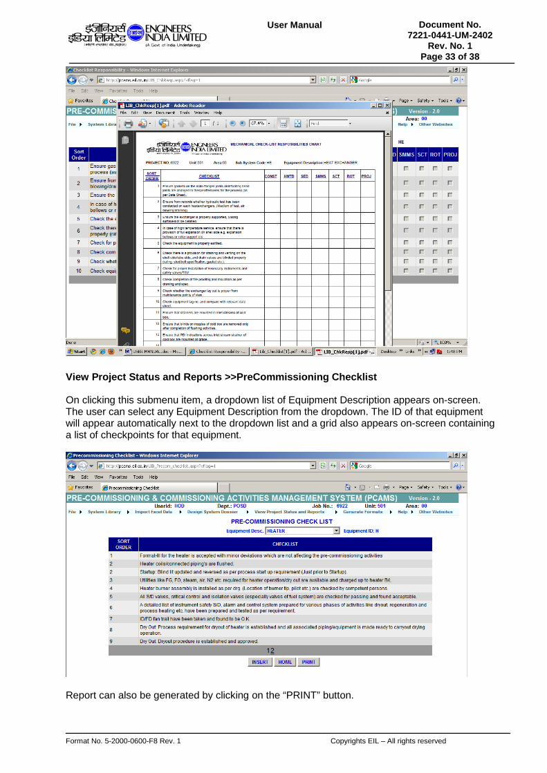
View Project Status and Reports >>PreCommissioning Checklist
On clicking this submenu item, a dropdown list of Equipment Description appears on-screen. The user can select any Equipment Description from the dropdown. The ID of that equipment will appear automatically next to the dropdown list and a grid also appears on-screen containing a list of checkpoints for that equipment.
Report can also be generated by clicking on the “PRINT” button.

Format No. 5-2000-0600-F8 Rev. 1 Copyrights EIL – All rights reserved
Document No. 7221-0441-UM-2402
Rev. No. 1 Page 34 of 38
User Manual
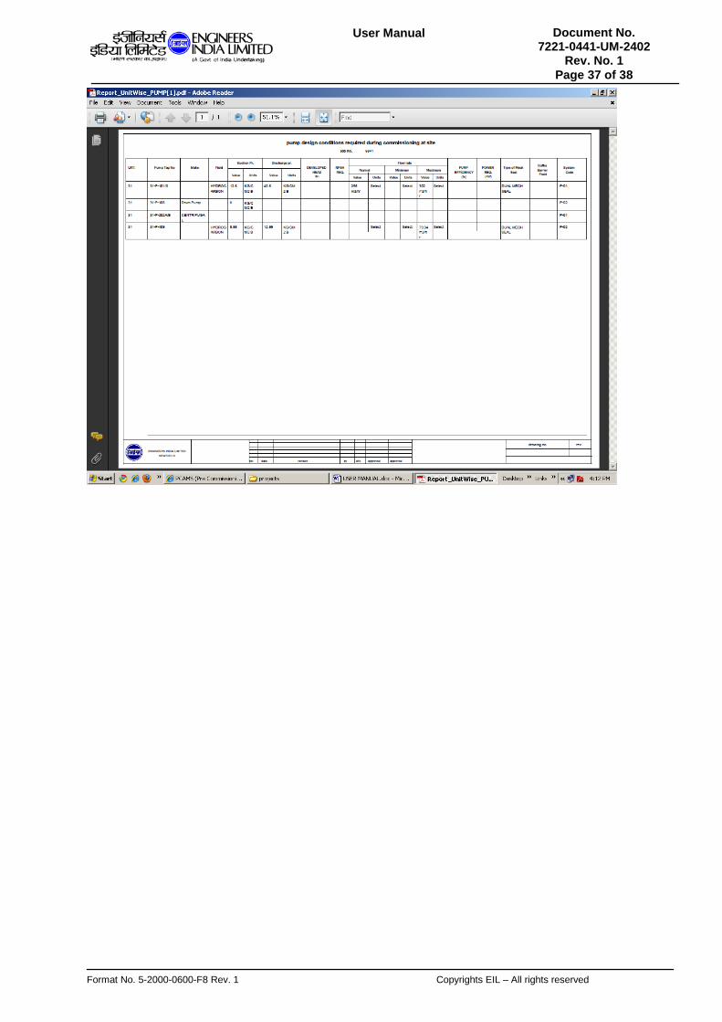
View Project Status and Reports >>View Design Data of critical equipment
The user can view the design parameters for some critical equipments and instruments through this module. First the user selects the category he wants to view i.e. equipment or instrument. The dropdown list for all the available equipments/instruments appears.
On choosing a particular type of instrument or equipment, Another panel appears -

Format No. 5-2000-0600-F8 Rev. 1 Copyrights EIL – All rights reserved
Document No. 7221-0441-UM-2402
Rev. No. 1 Page 35 of 38
User Manual
The second panel contains two areas – one for displaying the parameters and the other for printing reports. In the view area, the user first selects the data sheet no for the selected equipment/instrument type.
Based on his selection of datasheet, tag nos. of corresponding equipment/instrument appear. The view button is disabled up to this stage.

Format No. 5-2000-0600-F8 Rev. 1 Copyrights EIL – All rights reserved
Document No. 7221-0441-UM-2402
Rev. No. 1 Page 36 of 38
User Manual
The user now selects the equipment/instrument tag, which he wants to view. The view button gets enabled and on clicking on the same, a pop up window opens that displays all the design parameters for the selection criteria.
The print area has two options – unit wise and area wise printing. Based on the category(equipment or instrument) and type selected , print out of design parameters for all the equipments/instruments for that unit or area (determined by the option selected in the print area) in the current project may be viewed as a report.
Format No. 5-2000-0600-F8 Rev. 1 Copyrights EIL – All rights reserved
Document No. 7221-0441-UM-2402
Rev. No. 1 Page 37 of 38
User Manual

Format No. 5-2000-0600-F8 Rev. 1 Copyrights EIL – All rights reserved
Document No. 7221-0441-UM-2402
Rev. No. 1 Page 38 of 38
User Manual