sectional view.pdf
DESCRIPTION
Engineering Drawing - Sectional View lecture notes.TRANSCRIPT
ME 121 – Engineering Drawing and Graphics (Spring 2013)
Sectional View
ME 121 – Engineering Drawing and Graphics (Spring 2013)
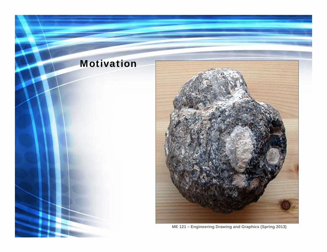
Motivation

ME 121 – Engineering Drawing and Graphics (Spring 2013)
Motivation
ME 121 – Engineering Drawing and Graphics (Spring 2013)
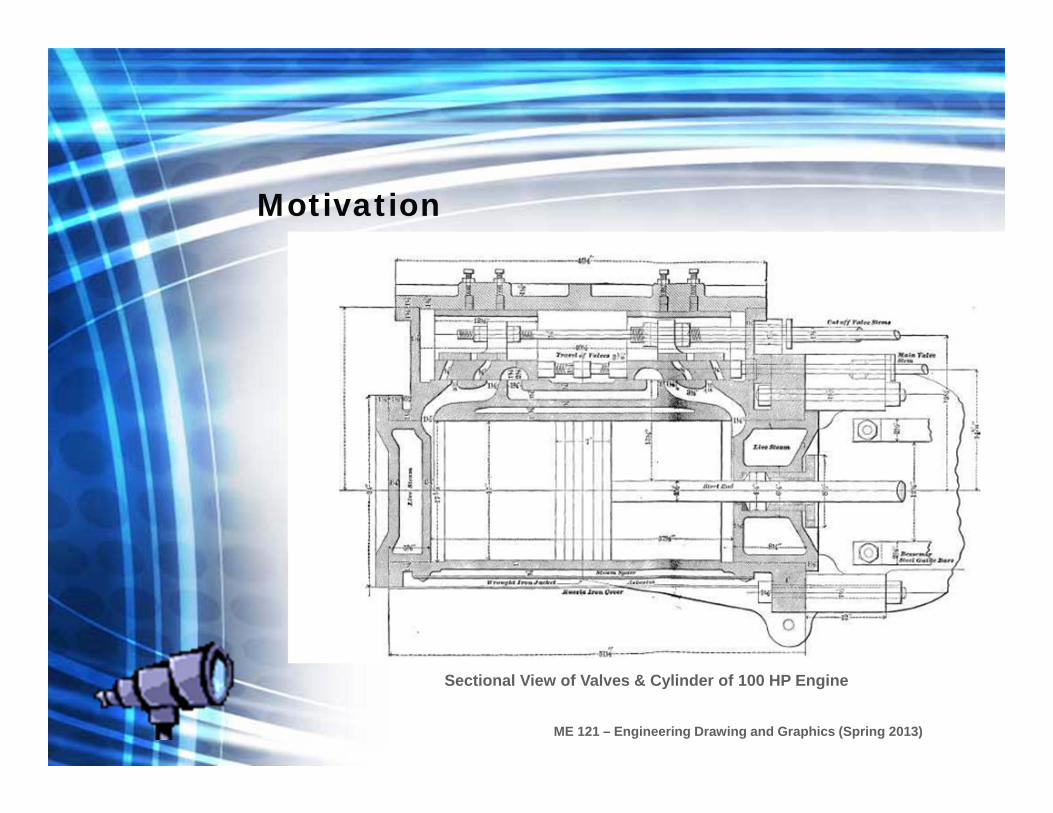
Sectional View of Valves & Cylinder of 100 HP Engine
Motivation
ME 121 – Engineering Drawing and Graphics (Spring 2013)
Introduction
• A sectional view represents the part of an object which remains after a portion has been removed.
• Used to show hidden shape or form• Will help to clarify what would normally be shown as hidden
detail• Only solid material being cut is sectioned• The section is obtained by cutting the component into two
parts at some good points• Sectioning symbol or hatching should be used to indicate the
part that has been cut.
ME 121 – Engineering Drawing and Graphics (Spring 2013)
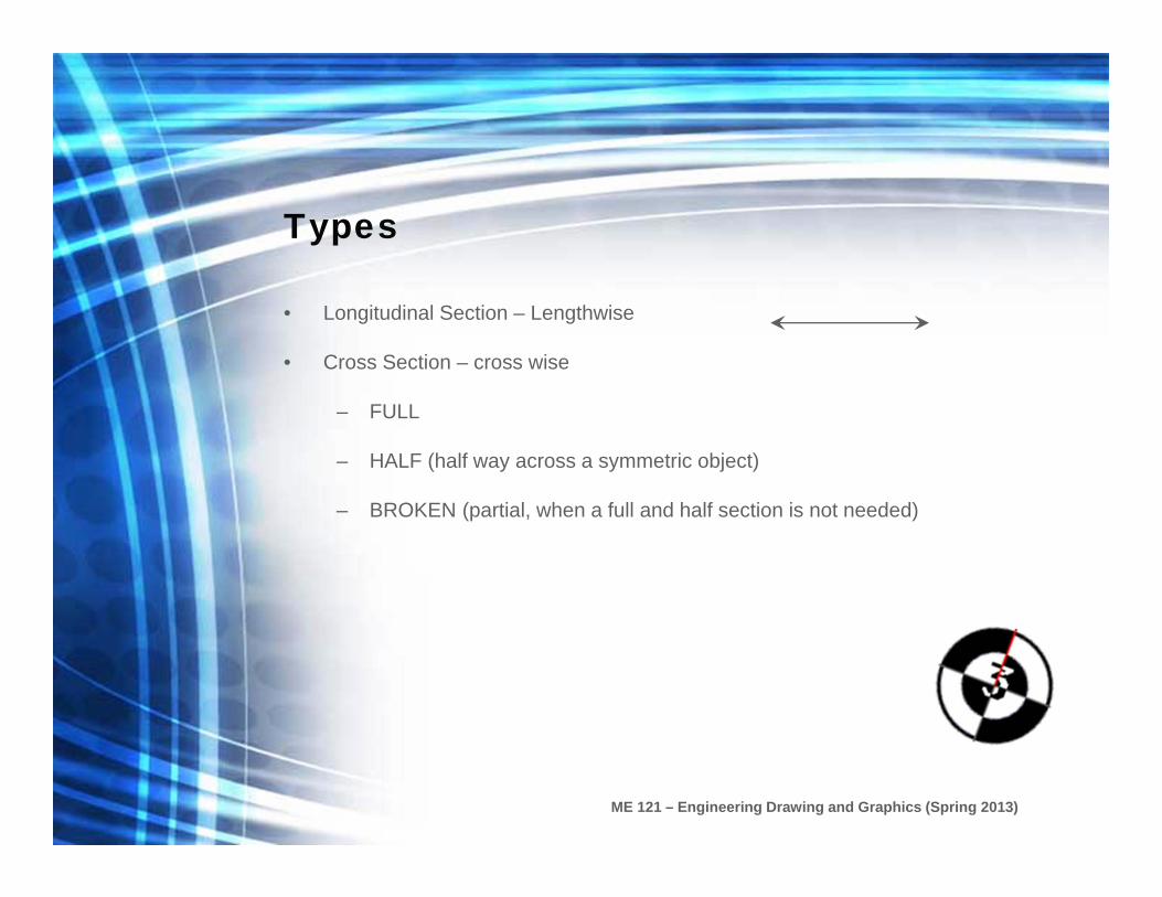
Types
• Longitudinal Section – Lengthwise
• Cross Section – cross wise
– FULL
– HALF (half way across a symmetric object)
– BROKEN (partial, when a full and half section is not needed)
ME 121 – Engineering Drawing and Graphics (Spring 2013)
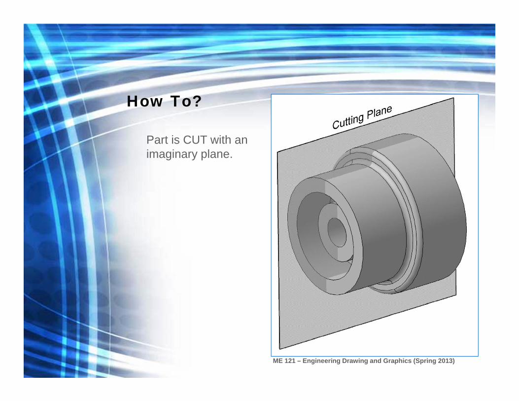
How To?
Part is CUT with an imaginary plane.
ME 121 – Engineering Drawing and Graphics (Spring 2013)
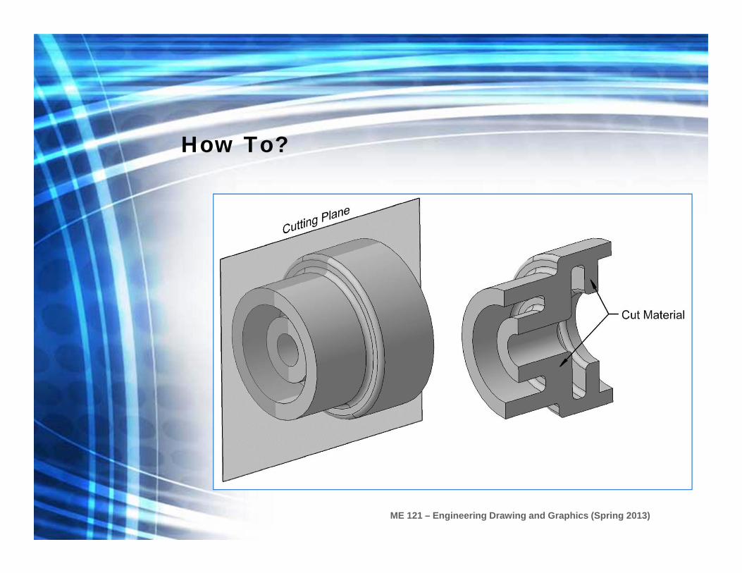
How To?
ME 121 – Engineering Drawing and Graphics (Spring 2013)
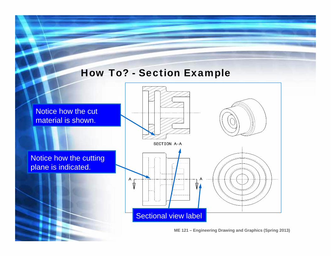
How To? - Section Example
Notice how the cutting plane is indicated.
Notice how the cut material is shown.
Sectional view label
ME 121 – Engineering Drawing and Graphics (Spring 2013)
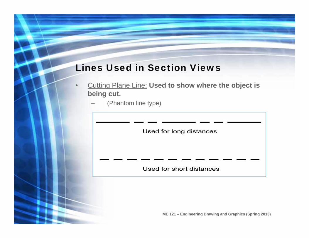
Lines Used in Section Views
• Cutting Plane Line: Used to show where the object is being cut.
– (Phantom line type)

ME 121 – Engineering Drawing and Graphics (Spring 2013)
How To? - Lines Used in Section Views
Shows where the part is being cut.
Arrows point to the portion being kept.
Section Lines

ME 121 – Engineering Drawing and Graphics (Spring 2013)
Lines Used in Section Views
• Section Lines: Section lines are used to indicate where the cutting plane cuts the material.
– Section lines are thin lines. – Section line symbols are chosen according to the material of
the object – Section lines are generally drawn at a 45 angle.
ME 121 – Engineering Drawing and Graphics (Spring 2013)
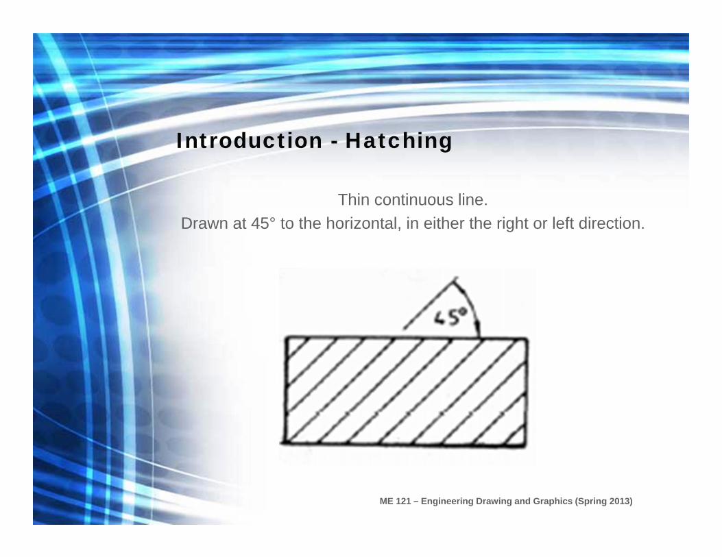
Introduction - Hatching
Thin continuous line. Drawn at 45° to the horizontal, in either the right or left direction.
ME 121 – Engineering Drawing and Graphics (Spring 2013)
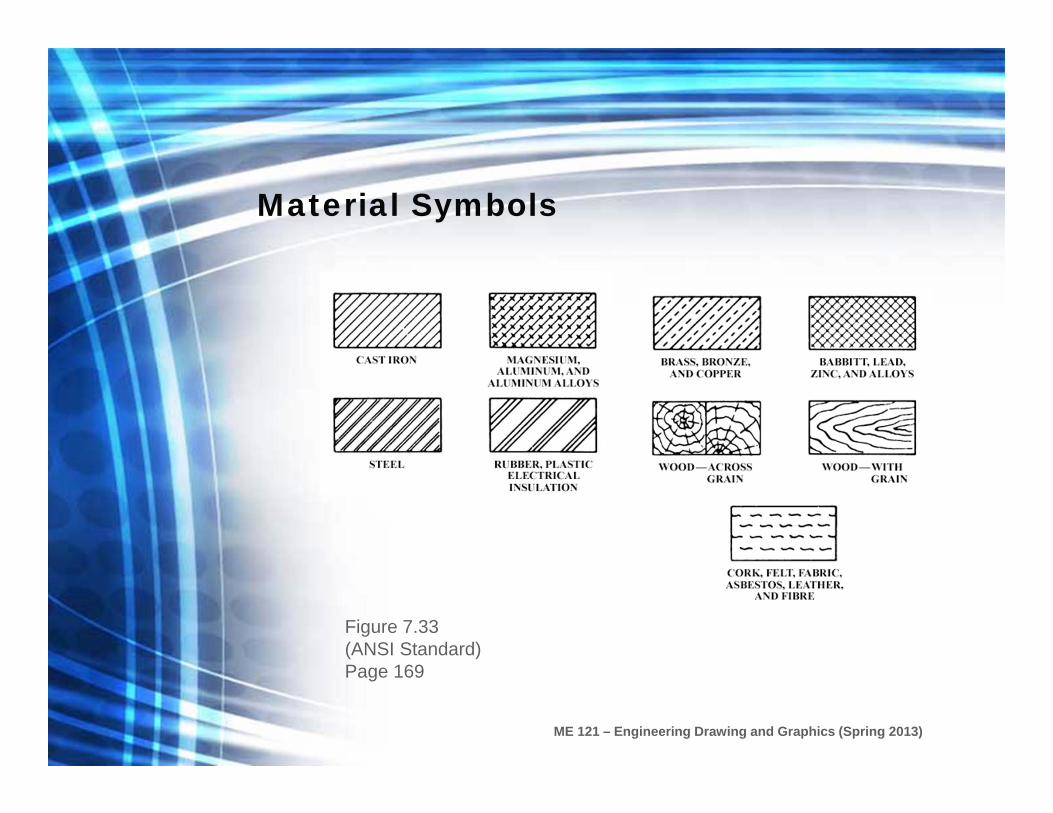
Material Symbols
Figure 7.33 (ANSI Standard)Page 169
ME 121 – Engineering Drawing and Graphics (Spring 2013)
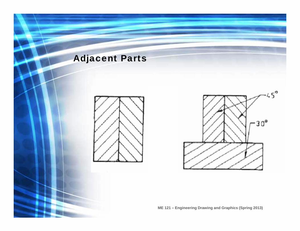
Adjacent Parts
ME 121 – Engineering Drawing and Graphics (Spring 2013)
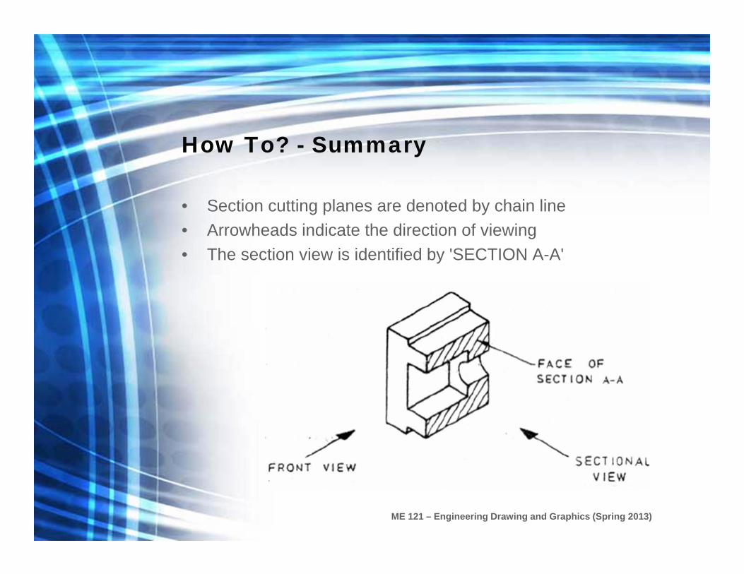
How To? - Summary
• Section cutting planes are denoted by chain line• Arrowheads indicate the direction of viewing• The section view is identified by 'SECTION A-A'
ME 121 – Engineering Drawing and Graphics (Spring 2013)
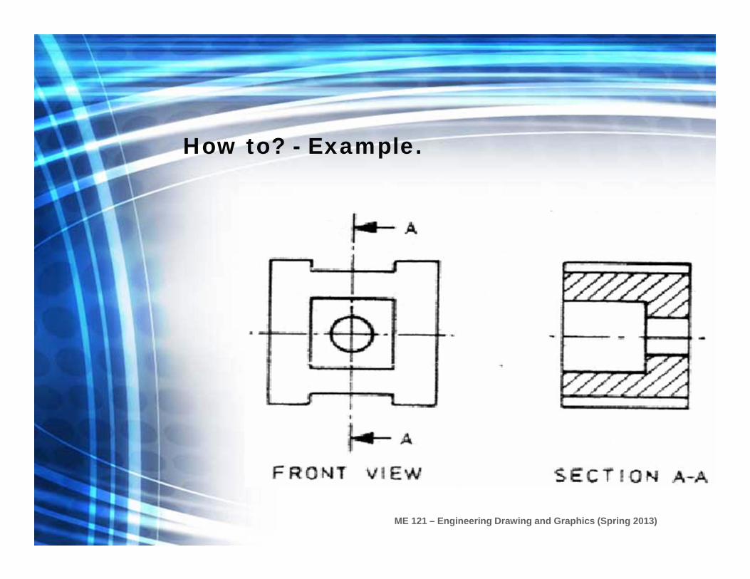
How to? - Example.
ME 121 – Engineering Drawing and Graphics (Spring 2013)
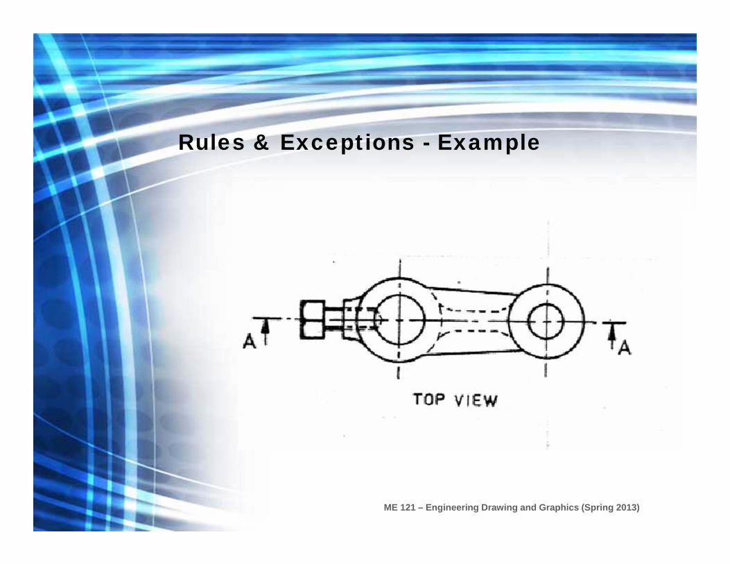
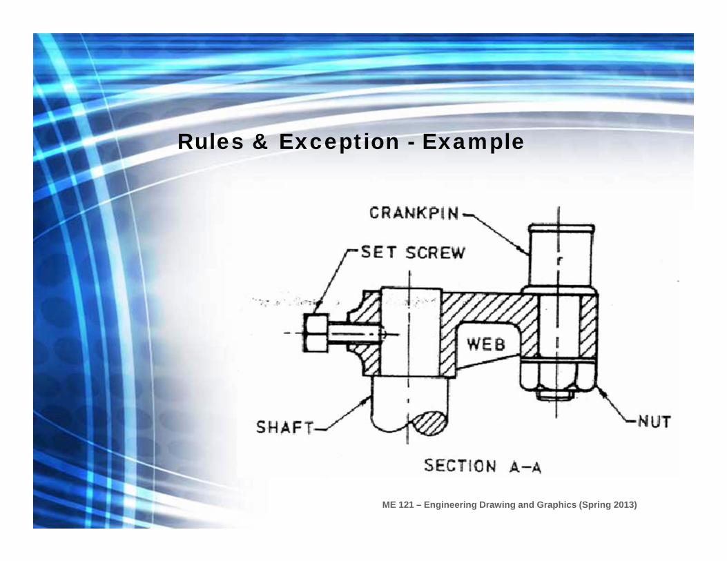
Rules & Exceptions
As general rule, all material cut by a cutting plane is hatched,
except for
web, shafts, bolts, rivets, keys, pins, and similar parts
ME 121 – Engineering Drawing and Graphics (Spring 2013)
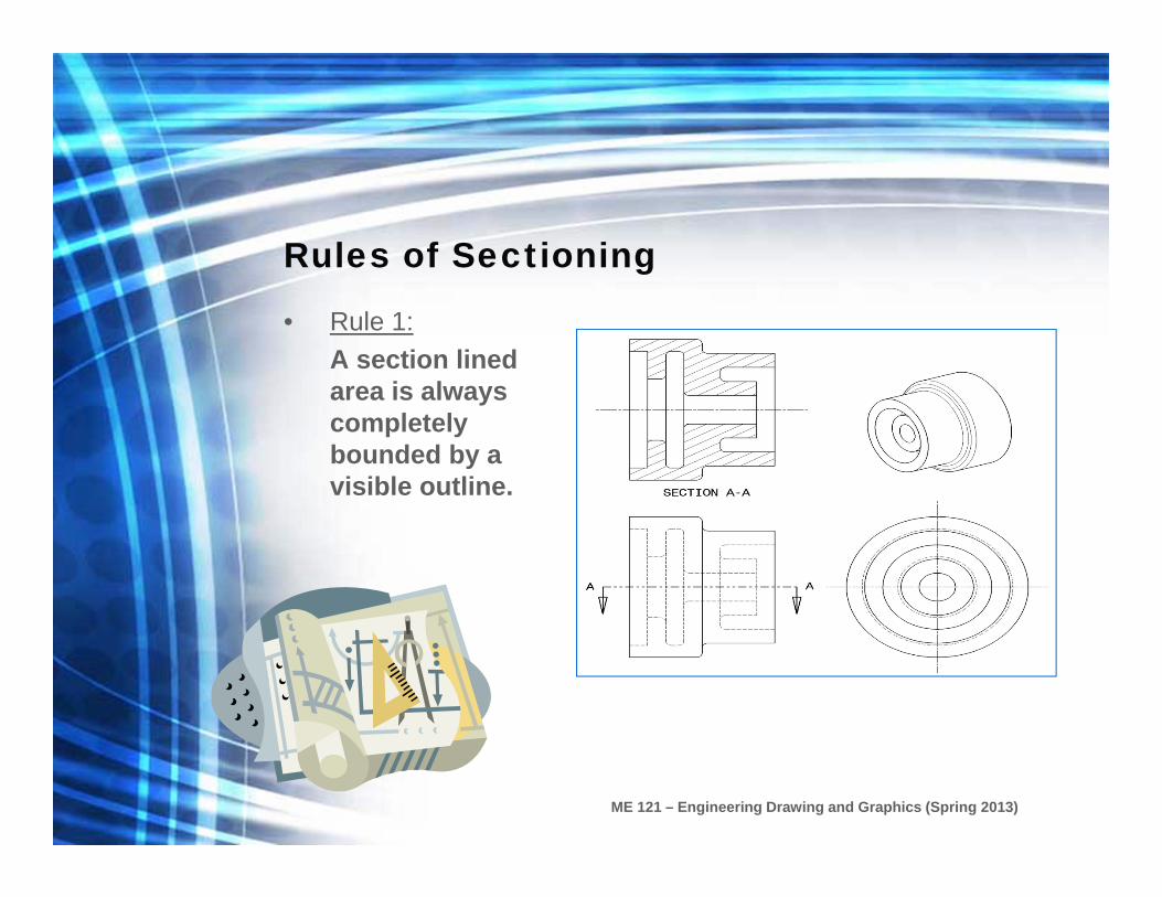
Rules of Sectioning
• Rule 1:A section lined area is always completely bounded by a visible outline.

ME 121 – Engineering Drawing and Graphics (Spring 2013)
Rules of Sectioning
• Rule 2:The section lines in all areas should be parallel.
– Section lines shown in opposite directions indicate a different part.

ME 121 – Engineering Drawing and Graphics (Spring 2013)
Rules of Sectioning
• Rule 3: All the visible edges behind the cutting plane should be shown.

ME 121 – Engineering Drawing and Graphics (Spring 2013)
Rules of Sectioning
• Rule 4:Hidden features should be omitted in all areas of a section view.
– Exceptions include threads and broken out sections.
ME 121 – Engineering Drawing and Graphics (Spring 2013)
Rules & Exceptions - Example
ME 121 – Engineering Drawing and Graphics (Spring 2013)
Rules & Exception - Example

ME 121 – Engineering Drawing and Graphics (Spring 2013)
Sectioning
Types of Sections

ME 121 – Engineering Drawing and Graphics (Spring 2013)
Types of Sections
• The type of section used depends on the situation and what information needs to be conveyed.
• Types of sections– Full Section– Half Section– Offset Section– etc …

ME 121 – Engineering Drawing and Graphics (Spring 2013)
Full Section
ME 121 – Engineering Drawing and Graphics (Spring 2013)
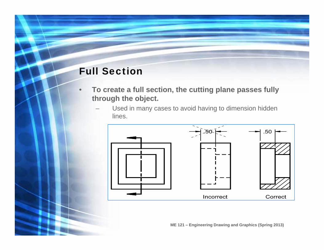
Full Section
• To create a full section, the cutting plane passes fully through the object.
– Used in many cases to avoid having to dimension hidden lines.

ME 121 – Engineering Drawing and Graphics (Spring 2013)
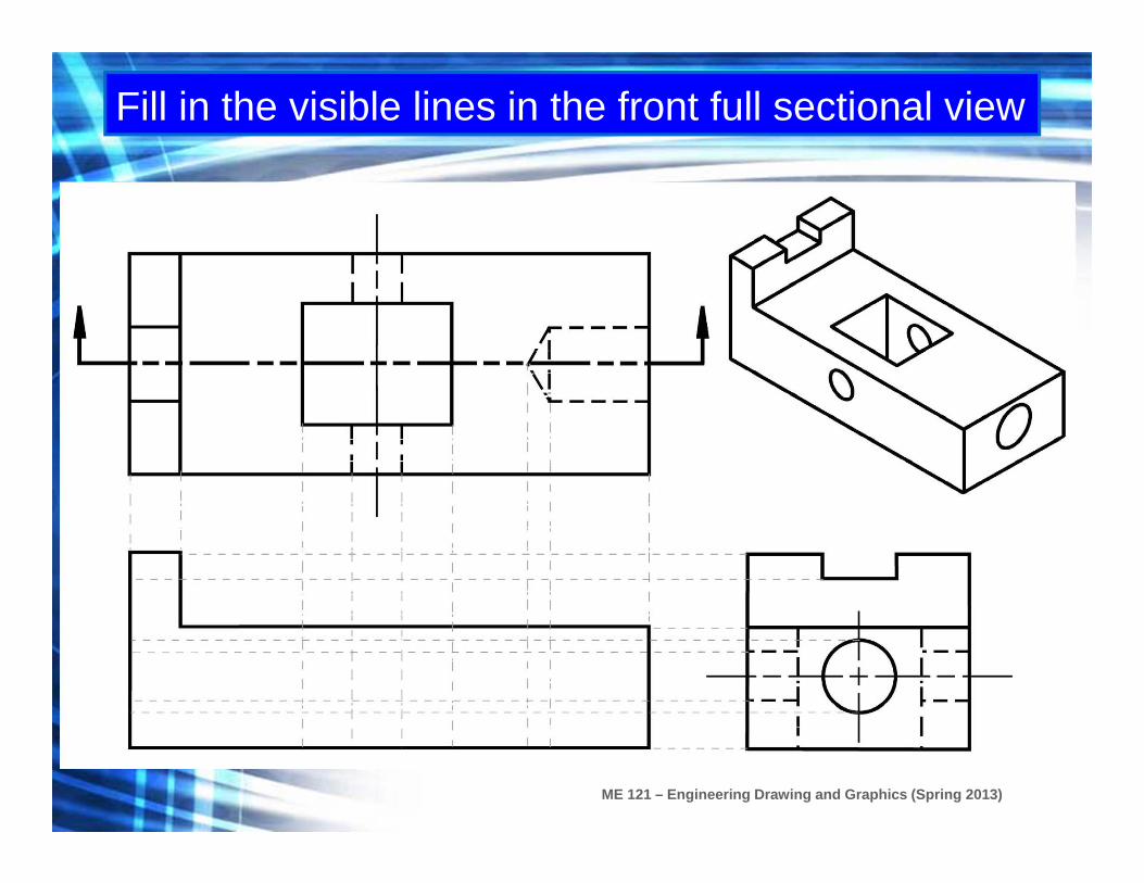
Exercise
• Given the top and right side views, sketch the front view as a full section.
– The material used is steel.
ME 121 – Engineering Drawing and Graphics (Spring 2013)
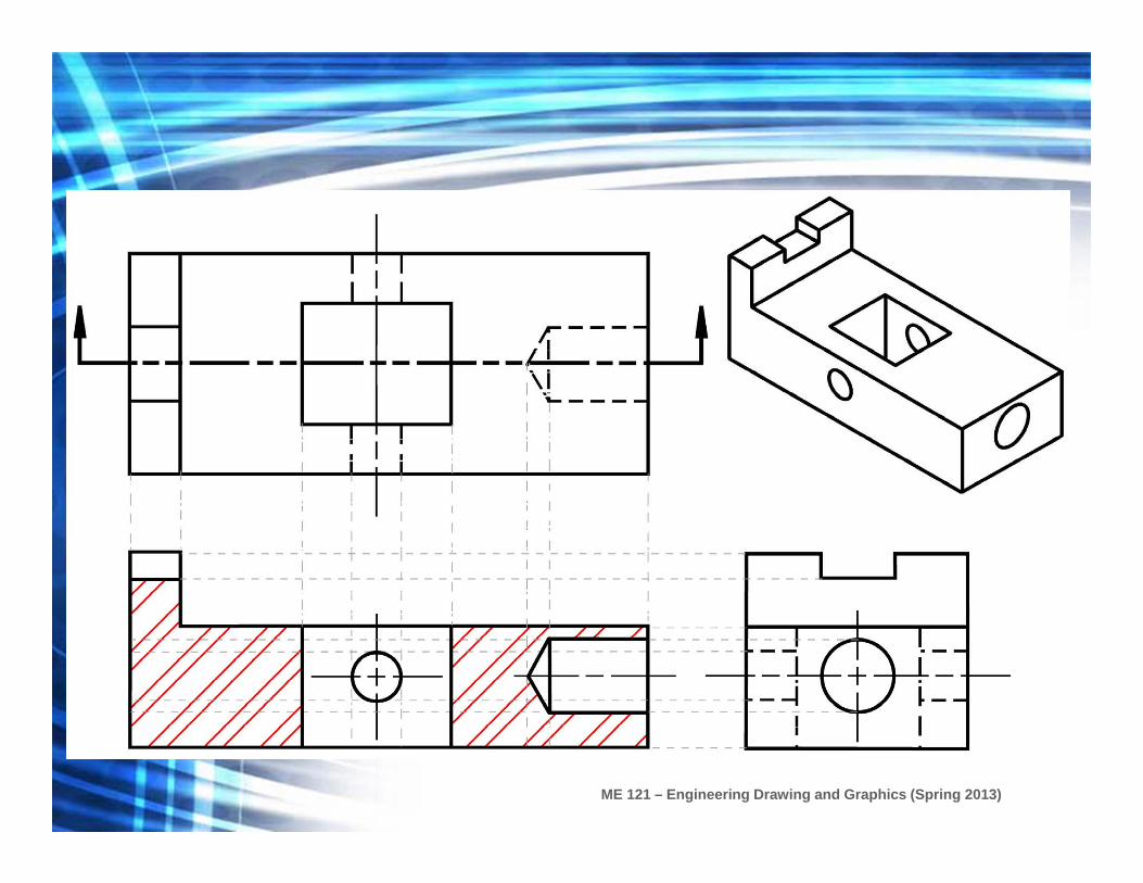
Fill in the visible lines in the front full sectional view

ME 121 – Engineering Drawing and Graphics (Spring 2013)

ME 121 – Engineering Drawing and Graphics (Spring 2013)
Fill in the section lines in the front full sectional view
ME 121 – Engineering Drawing and Graphics (Spring 2013)
ME 121 – Engineering Drawing and Graphics (Spring 2013)
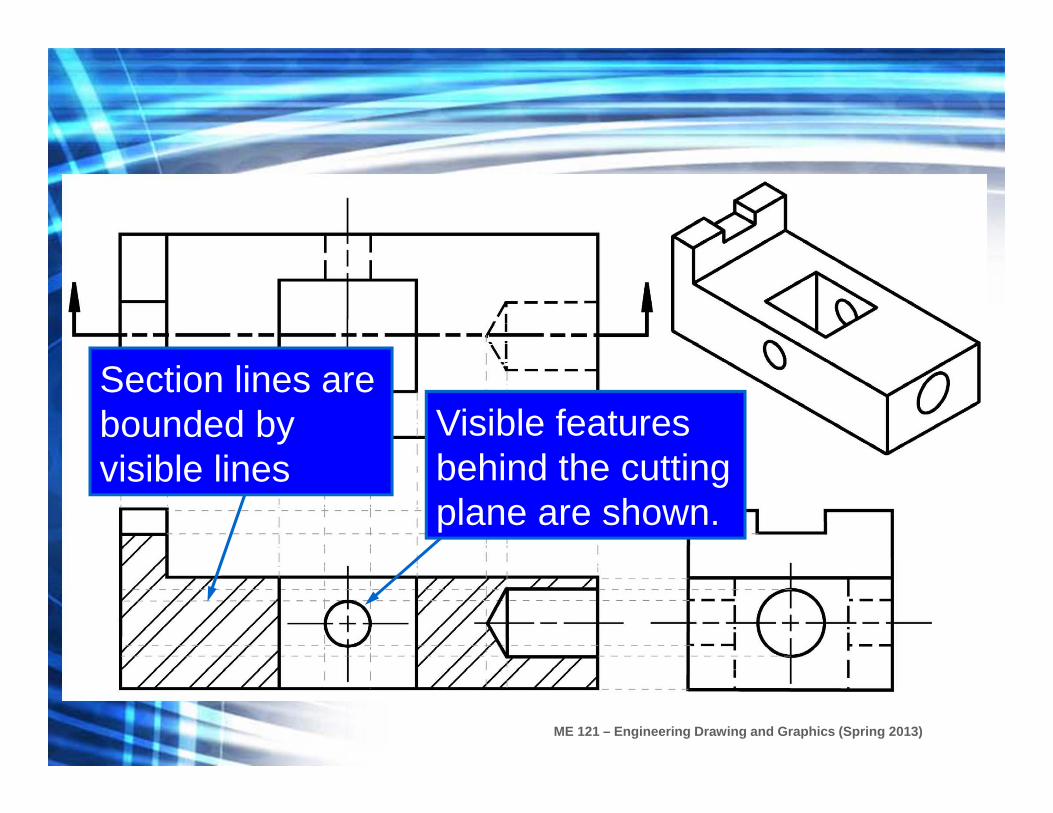
Section lines are bounded by visible lines
Visible features behind the cutting plane are shown.

ME 121 – Engineering Drawing and Graphics (Spring 2013)
Orthogonal View of a Section

ME 121 – Engineering Drawing and Graphics (Spring 2013)
Isometric Full Section View Example

ME 121 – Engineering Drawing and Graphics (Spring 2013)
Half Section
ME 121 – Engineering Drawing and Graphics (Spring 2013)
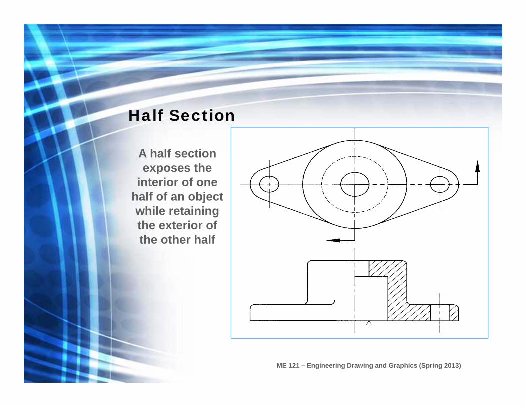
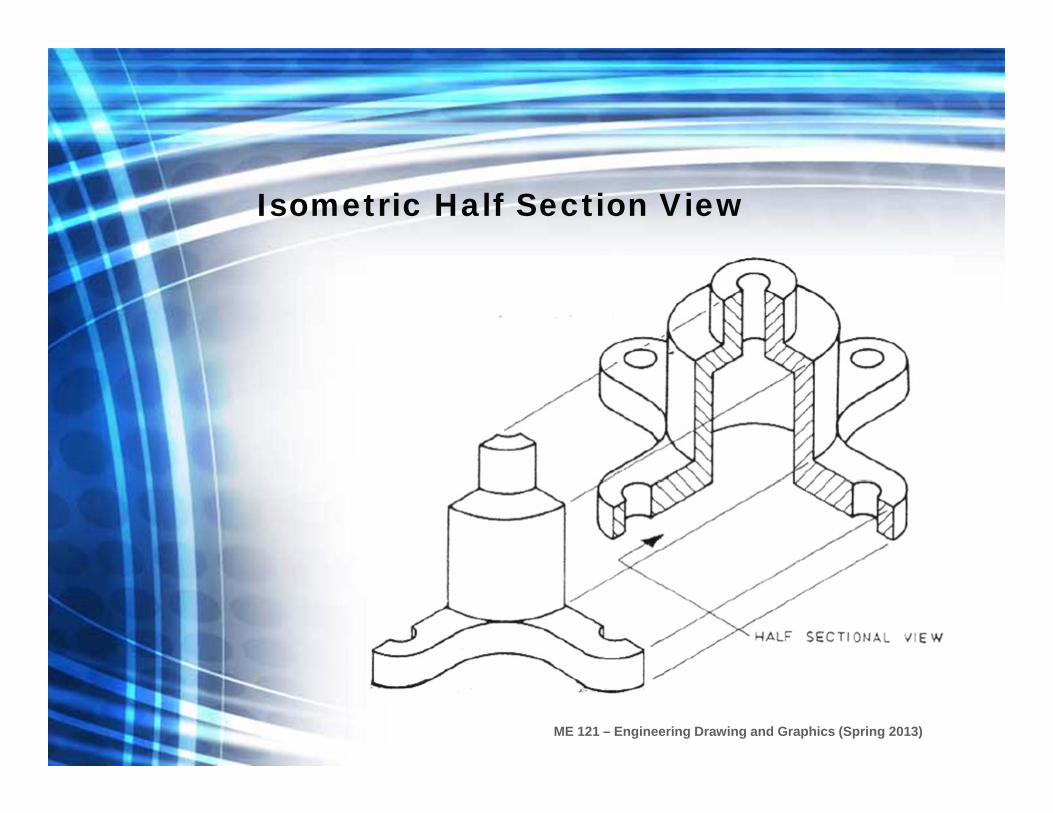
Half Section
A half section exposes the
interior of one half of an object while retaining the exterior of the other half
ME 121 – Engineering Drawing and Graphics (Spring 2013)
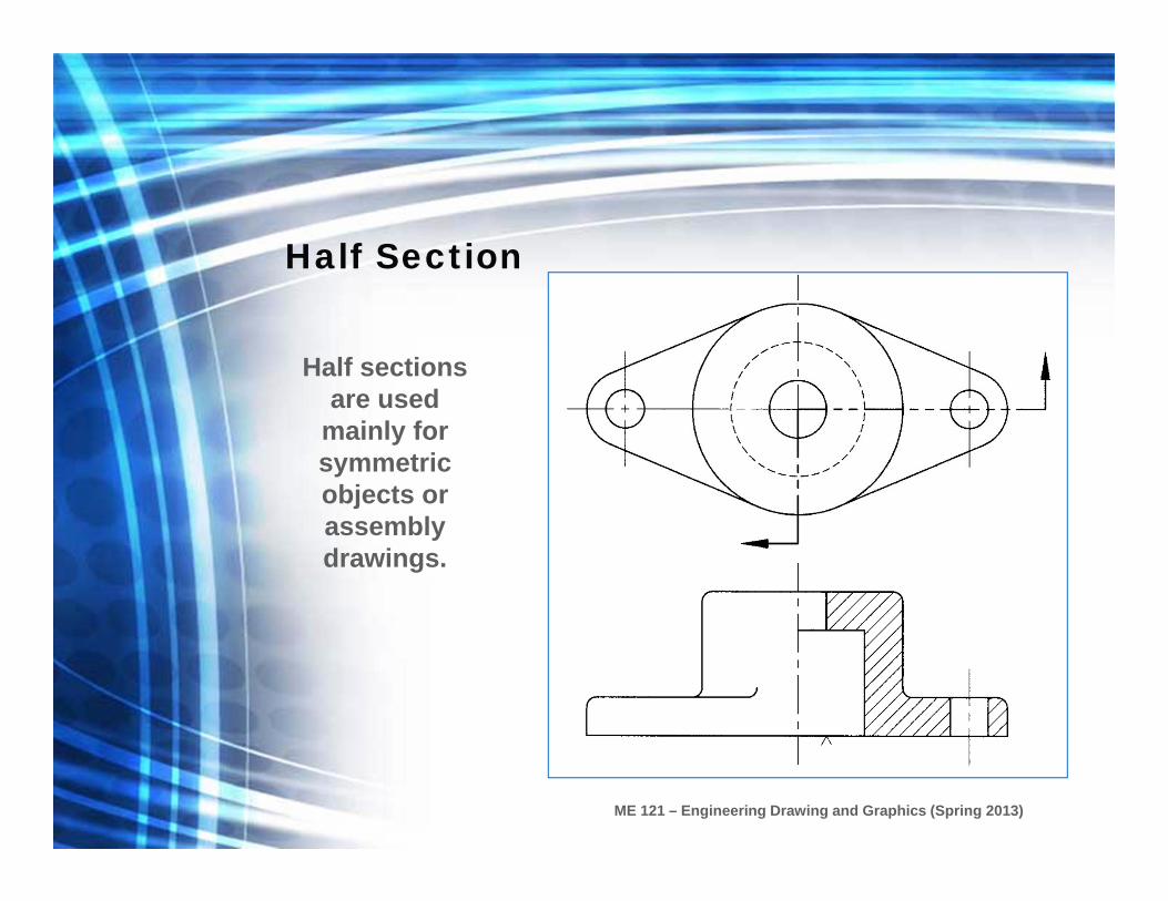
Half Section
Half sections are used
mainly for symmetric objects or assembly drawings.
ME 121 – Engineering Drawing and Graphics (Spring 2013)
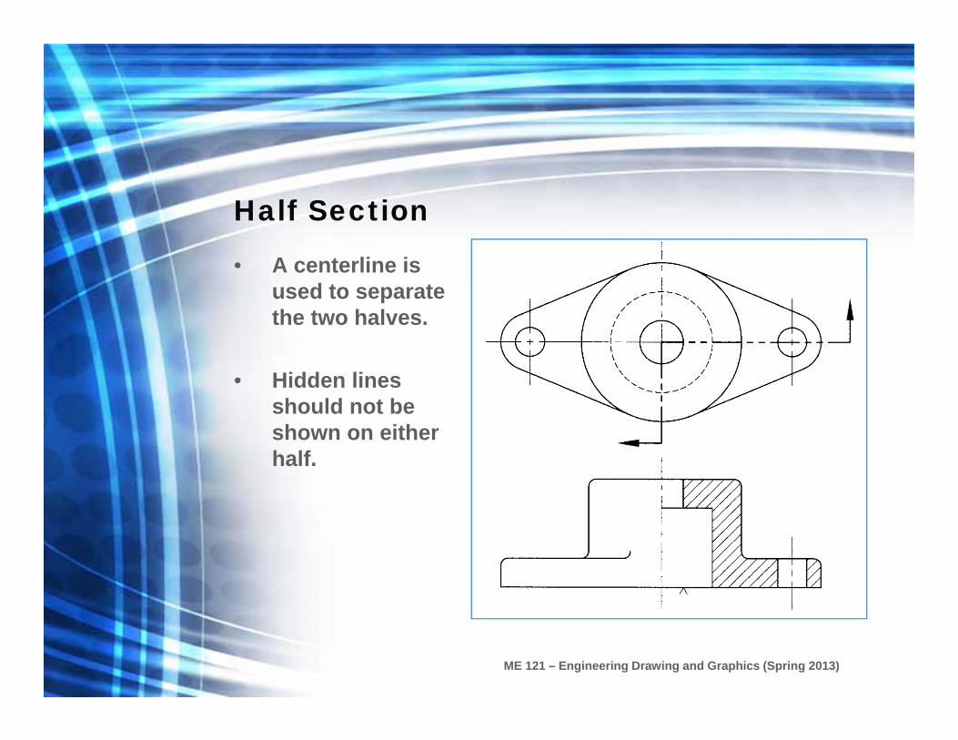
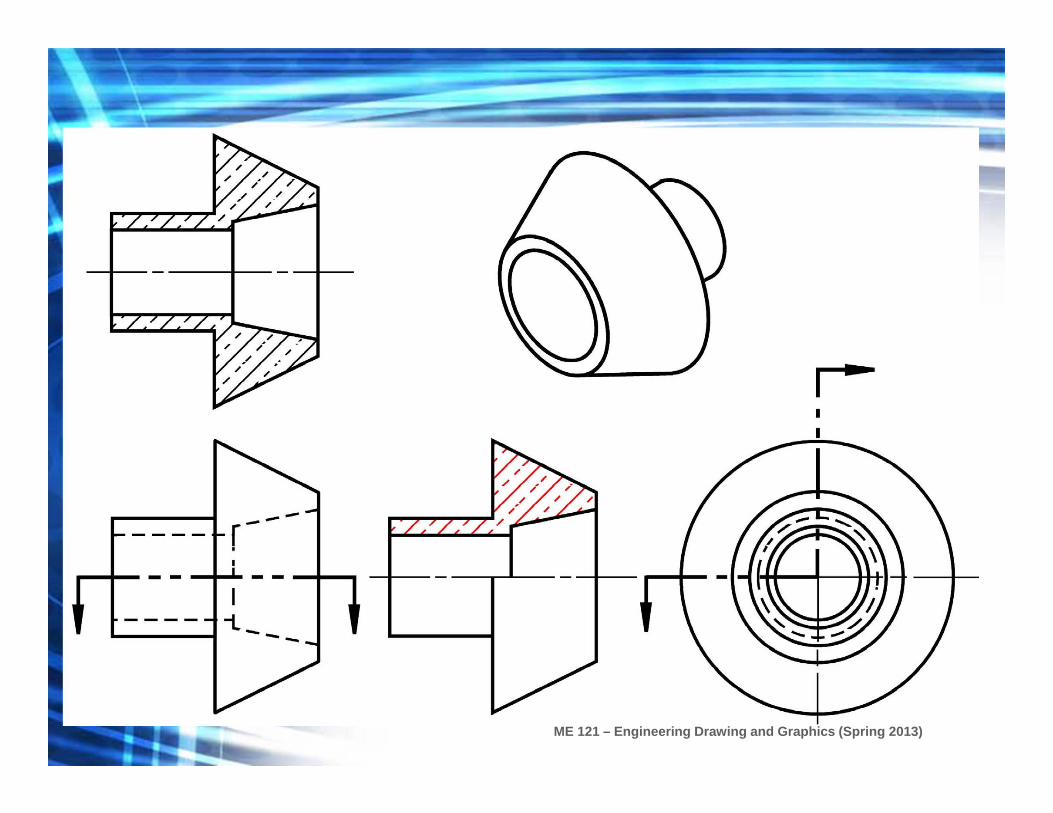
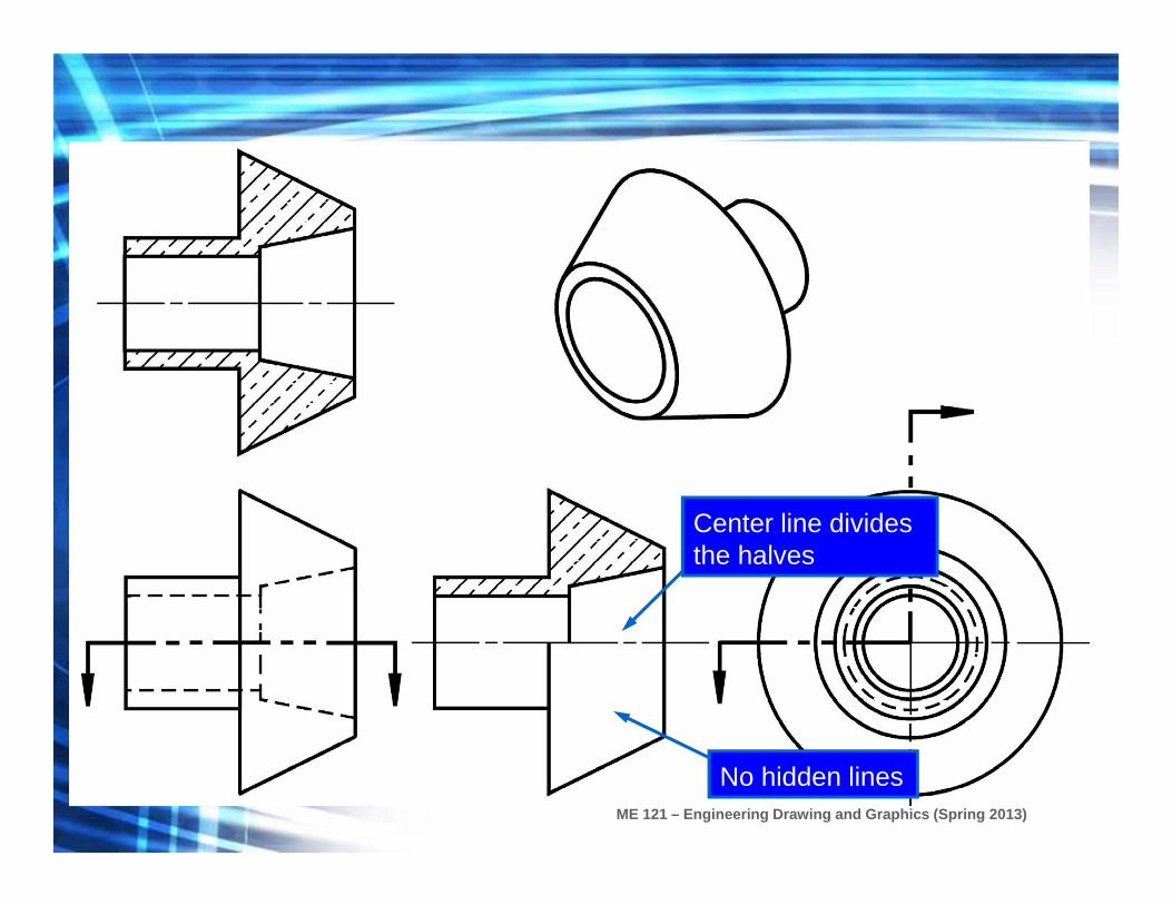
Half Section
• A centerline is used to separate the two halves.
• Hidden lines should not be shown on either half.
ME 121 – Engineering Drawing and Graphics (Spring 2013)
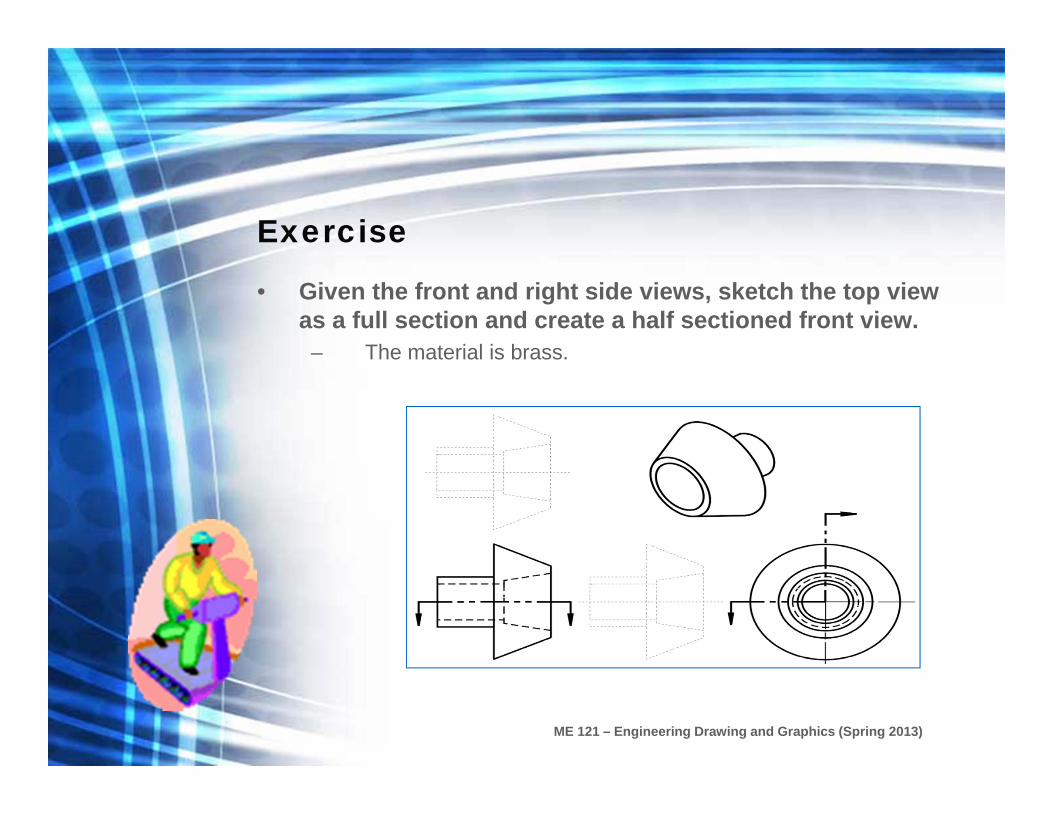
Exercise
• Given the front and right side views, sketch the top view as a full section and create a half sectioned front view.
– The material is brass.

ME 121 – Engineering Drawing and Graphics (Spring 2013)
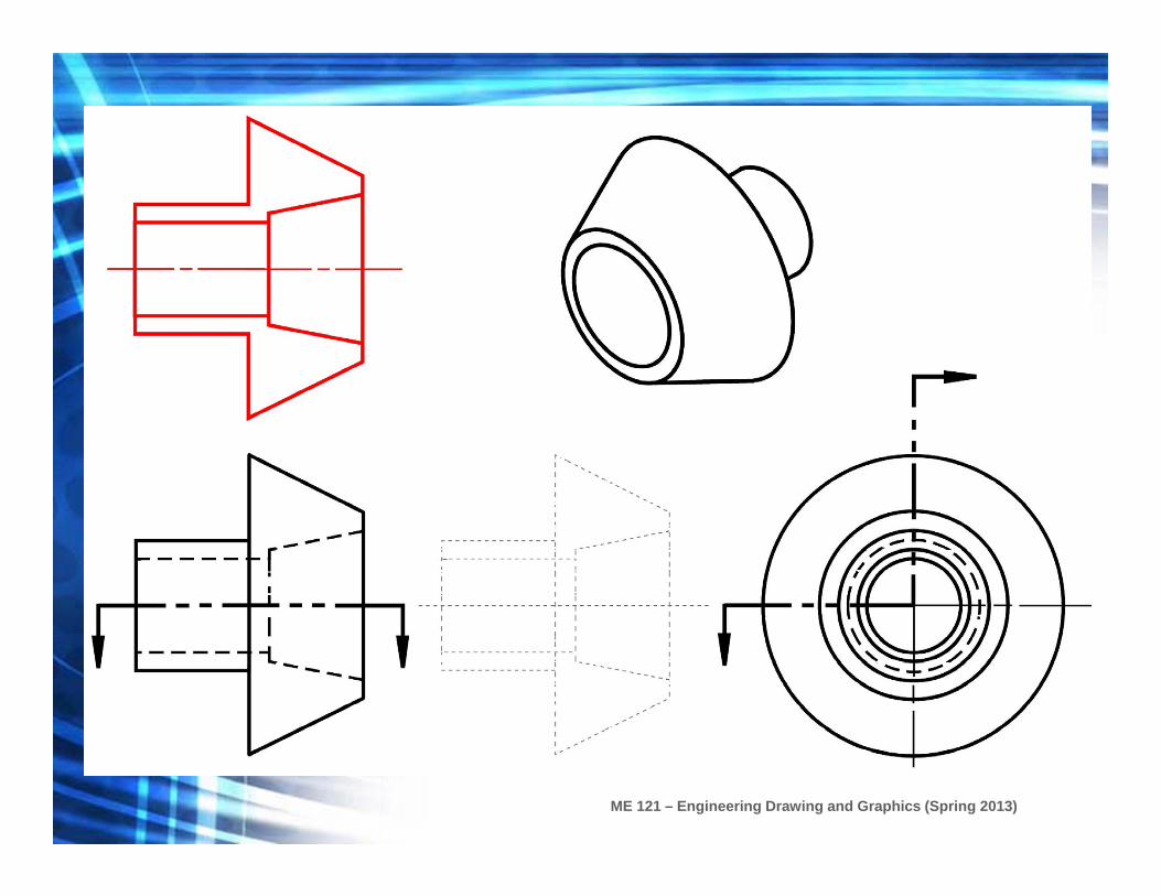
Fill in the visible lines in the top full section view.
ME 121 – Engineering Drawing and Graphics (Spring 2013)

ME 121 – Engineering Drawing and Graphics (Spring 2013)
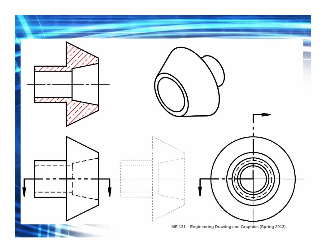
Fill in the section lines in the top full section view.
ME 121 – Engineering Drawing and Graphics (Spring 2013)

ME 121 – Engineering Drawing and Graphics (Spring 2013)
Fill in the visible lines in the right side half section view.

ME 121 – Engineering Drawing and Graphics (Spring 2013)

ME 121 – Engineering Drawing and Graphics (Spring 2013)
Fill in the section lines in the right side half section view.
ME 121 – Engineering Drawing and Graphics (Spring 2013)
ME 121 – Engineering Drawing and Graphics (Spring 2013)
No hidden lines
Center line divides the halves
ME 121 – Engineering Drawing and Graphics (Spring 2013)
Isometric Half Section View

ME 121 – Engineering Drawing and Graphics (Spring 2013)
Orthogonal Section View
ME 121 – Engineering Drawing and Graphics (Spring 2013)
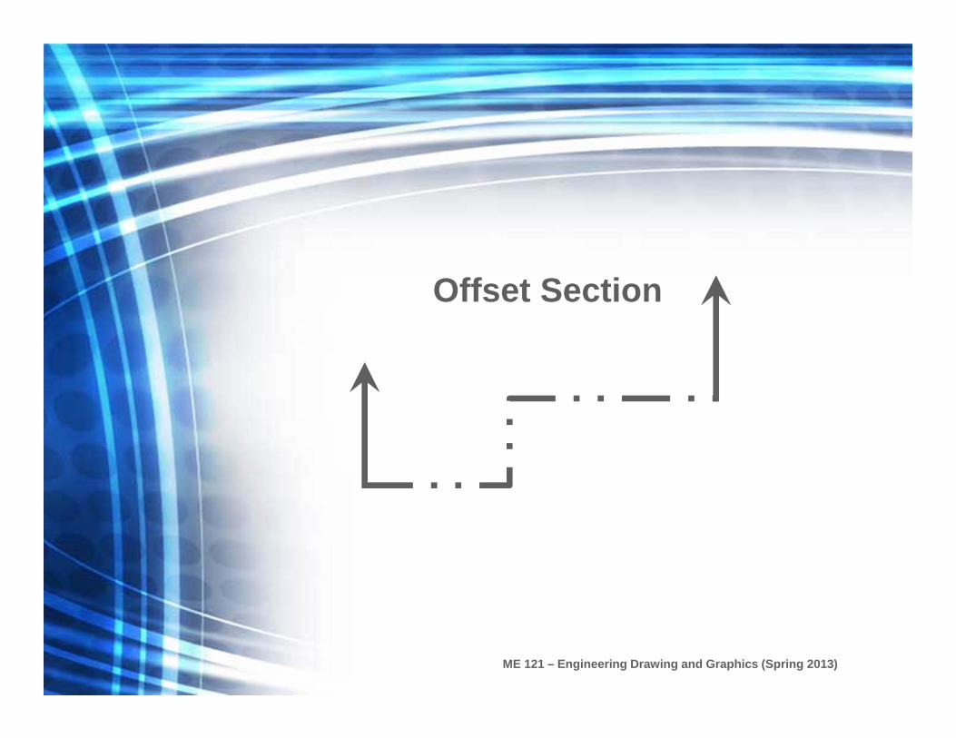
Offset Section

ME 121 – Engineering Drawing and Graphics (Spring 2013)
Offset SectionAn offset section is produced by bending the cutting plane to show features that don’t lie in the same plane.

ME 121 – Engineering Drawing and Graphics (Spring 2013)
Offset Sectional ViewIsometric view of an offset section

ME 121 – Engineering Drawing and Graphics (Spring 2013)
Orthogonal View of an Offset Section
ME 121 – Engineering Drawing and Graphics (Spring 2013)
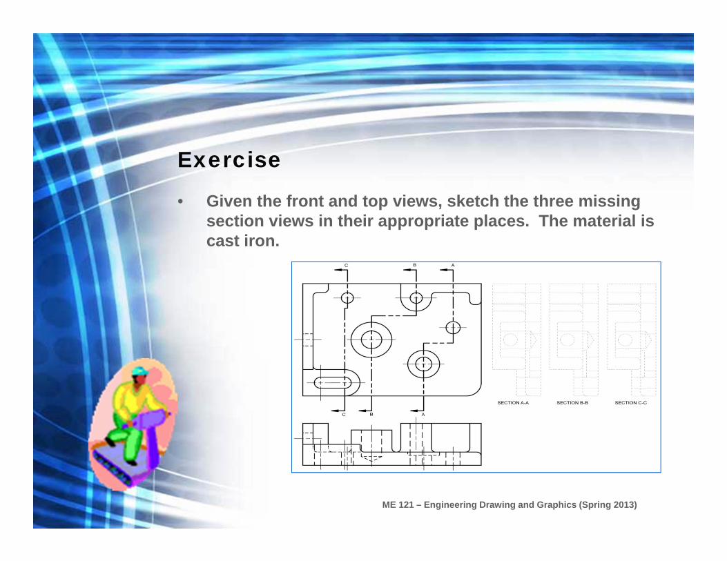
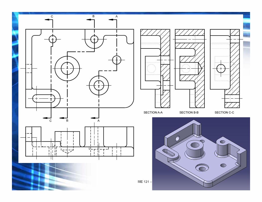
Exercise
• Given the front and top views, sketch the three missing section views in their appropriate places. The material is cast iron.

ME 121 – Engineering Drawing and Graphics (Spring 2013)

ME 121 – Engineering Drawing and Graphics (Spring 2013)

ME 121 – Engineering Drawing and Graphics (Spring 2013)
ME 121 – Engineering Drawing and Graphics (Spring 2013)