video and thermography analysis system - palgo · video and thermography analysis system . ......
TRANSCRIPT

smart solutions for combustion and environment
Video and Thermography Analysis System

The Thermography Analysis System
The thermography system comprises the compo-nents of the video system plus the system com-puter with software modules. It operates as a spatial optical pyrometer on thebasis of image data processing and offers, in ad-dition to the video system:
● Temperature determination of each visibleimage point of the video sensor
● Thermal analysis of the local temperature dis-tribution
● Temperature definition within freely definablemeasuring window and lines (ROI = Region ofInterest / LOI = Line Of Interest).
● Analysis of thermal samples to identify anom-alies in the combustion process
All data of the thermography system can betransmitted to the process control system via astandardized data interface.
Video Monitoring ThermographyThe Field Components
● Pneumatically operated retraction systemwith monitoring units for the cooling andflushing media, including integrated air accu-mulator
● Field control cabinet for control of the sen-sors, signal processing for the data and videotransmission via fibre-optic cable to the con-trol room.
The Control Room Equipment
● System computer for temperature calculation,thermography presentation
● Video monitor for online colour display
The Video System
The basic system comprises the above-men-tioned system components, without system com-puter. It enables visual monitoring through real-time colour video display.
The D-VTA 100-10 Video and Thermography System
is a modular system for monitoring industrialhigh temperature processes. Intelligent sensorsallow contactless, optical and thermal onlineanalysis of processes in the combustion chamber.Applications include:
● Burning analysis and slag monitoring in pow-er plants
● Visualization of flame post combustion cham-bers and flame front monitoring in waste in-cineration plants
● Monitoring ore calcination and hazardouswaste disposal in the chemical industry
● Annealing and pusher furnace monitoring inthe steel industry
● Scale formation and melting charge control inthe glass industry.
The Sensors
have been specially developed for the harshworking conditions in industrial combustions. The sensor housing contains the special boro-scope as optical system, or the videoscope andthe industrial CCD camera. In this design all elec-tronic components are operated outside the kilnarea, in the cooled camera housing. The slim, air or water-cooled sensor shaft(Ø 43mm) minimises the mechanical stress (abra-sive dust) and the thermal influence on the sen-sor parts in the combustion chamber.The optical system is protected against mechani-cal and thermal damage by sapphire glass at thesensor tip, in addition to air flushing. As no mov-ing parts (no mirrors, prisms or motors) are locat-ed in the process-oriented area, the sensorsachieve a high availability with minimum servicerequirement.
Furnace Camera with Retraction Unit (water-cooled)
Waste Incineration Plant Power Plant Chemical Industry
Video system PAL, picture elements: 752(H) x 582(V), fixed focus
Thermographyfrom total radiation
Temperature range 1000°C – 1800°C
Optical alignment Sensor 0°: axially-parallel tosensor axis, Sensor45°: angled 45° to sensor axis
Optical field ofview
Sensor 0°: horizontal 72°, vertical 54°,diagonal 90°;Sensor 45°: horizontal 48°, vertical 36°,diagonal 60°
Data interfaces onthe system PC
RS232, RS422, RS485: ASCII, MODBUS, Siemens RK512;Ethernet: TCP/IP: FTP, MODBUS
Auxiliary energy 230 V / 50 Hz, 500 VA
Gas temperature incombustionchamber
Water-cooled sensor <1800°C
Ambienttemperature
Sensor / Retraction: 0°C…60°C,Field control cabinet: 0°C…45°C
Material Sensor: stainless steel 1.4571 /1.4301, Field control cabinet:steel sheet, painted in RAL 7035
Dimensions /Weights
Diameter of sensor tip: water-cooled 43 mm
Immersion depthin combustionchamber
max. 450 mm from welding plate
Space requirementfor sensor /retraction device
1450 x 500 x 800 mm (LxWxH)
Stroke of retractiondevice 700 mm
Field cabinet 600 x 380 x 210 mm (HxWxD)
Cable length Sensor/Retraction – Field controlcabinet 10 m
System PC 19" industrial housing, 4 HE,depth 450 mm
Weights Sensor with retraction andcarrier 70 kg, Field control cabinet 15 kg
Cooling watervolume 350 l/h, 1.5…8 barg
Cooling water temperature
Inlet: <45°C, Outlet: Temperatureincrease <10° C
Cooling waterquality
Clean, chemically neutral, non-corrosive, Hardness: <5°dH / <28 mMol/l
Compressed airvolume max. 25 Nm3/h
Compressed airpressure 5 – 8 barg
Compressed airtemperature 5…40°C
Compressed airquality dry, free from dust, aerosols, oil
Technical DataAnalysis System
Steel Industry Paper Industry Glas Industry
D-VTA 100-10 System in a Waste Incineration Plant
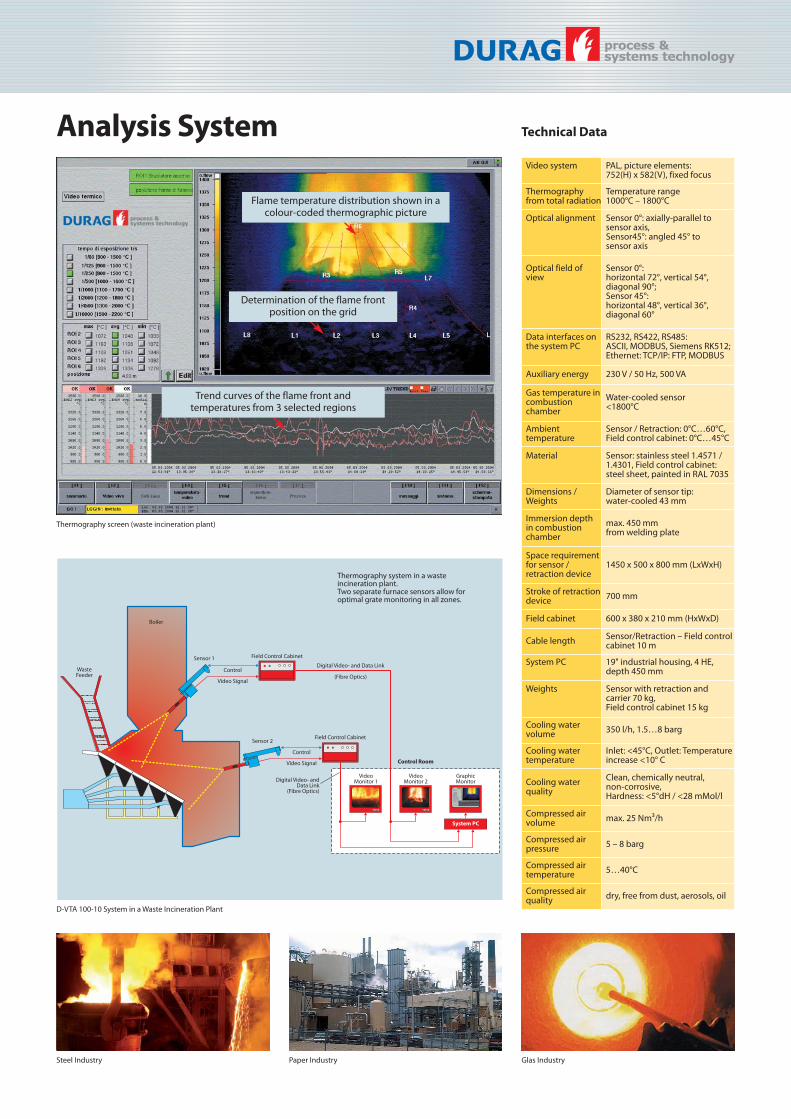
Thermography screen (waste incineration plant)
Trend curves of the flame front and temperatures from 3 selected regions
Determination of the flame front position on the grid
Thermography system in a wasteincineration plant. Two separate furnace sensors allow foroptimal grate monitoring in all zones.
Flame temperature distribution shown in a colour-coded thermographic picture

DURAG Inc.
DURAG UK
DURAG France DURAG GmbH
DURAG India
DURAG GmbHKollaustraße 10522453 Hamburg, GermanyTel.+49 (0)40 55 42 18-0Fax+49 (0)40 58 41 54E-Mail: [email protected]
DVN – DURAG Vertrieb/Service NordKollaustraße 10522453 Hamburg, GermanyTel.+49 (0)40 55 42 18-0Fax+49 (0)40 58 41 54E-Mail: [email protected]
DVO – DURAG Vertrieb/Service OstMeißner Ring 409599 Freiberg, GermanyTel.+49 (0)3731 30 04-0Fax+49 (0)3731 30 04-22E-Mail: [email protected]
DVS – DURAG Vertrieb/Service SüdWeidenweg 1673087 Bad Boll, GermanyTel.+49 (0)7164 912 25-0Fax+49 (0)7164 912 25-50 E-Mail: [email protected]
DVW – DURAG Vertrieb/Service WestAn der Pönt 53a40885 Ratingen, GermanyTel.+49 (0)2102 74 00-0Fax+49 (0)2102 74 00 28E-Mail: [email protected]
DURAG France S.a.r.l.Parc GIP Charles de Gaulle49, rue Léonard de Vinci, BP 7016695691 Goussainville CEDEX, FranceTel.+33 (0)1 301 811 80Fax+33 (0)1 393 383 60E-Mail: [email protected]
DURAG UK OfficeSuite 17, Brookside Business ParkCold Meece, Stone, Staffordshire ST15 0RZ, United KingdomTel.+44 (0)1785 760 007Fax+44 (0)1785 760 014E-Mail: [email protected]
DURAG, Inc., USA1355 Mendota Heights Road · Suite 200,Mendota Heights · MN 55120, USA Tel.+1 651 451-1710Fax+1 651 457-7684E-Mail: [email protected]
DURAG India Instrumentation Ltd#143/16, Ground Floor, 4th Main RoadIndustrial Town, RajajinagarBengalooru 560 044, IndiaTel.+91 (0)80 23 14 56 26 Fax+91 (0)80 23 14 56 26 Ext. 30E-Mail: [email protected]
www.durag.de
DURAG data systems GmbHKollaustraße 105, 22453 Hamburg, GermanyTel.+49 (0)3731 30 04-0Fax+49 (0)3731 30 04-22E-Mail: [email protected]
DURAG process & systems technology gmbhKollaustraße 10522453 Hamburg, GermanyTel.+49 (0)40 55 42 18-0Fax+49 (0)40 58 41 54E-Mail: [email protected]
Hegwein GmbHAm Boschwerk 770469 Stuttgart, GermanyTel.+49 (0)711 135 788-0Fax+49 (0)711 135 788-5E-Mail: [email protected]
Smitsvonk Holland B.V.P.O. Box 180, 2700 AD ZoetermeerLoodstraat 57, 2718 RV ZoetermeerNetherlandsTel.+31 (0)79 361 35 33Fax+31 (0)79 361 13 78E-mail: [email protected]
VEREWA Umwelt- und ProzessmesstechnikGmbHKollaustraße 10522453 Hamburg, GermanyTel.+49 (0)40 55 42 18-0Fax+49 (0)40 58 41 54E-Mail: [email protected]
smart solutions for combustion and environment
©DURAG GROUP 12/2008 · Subject to change without notice
Hammarvägen 1 040 - 664 28 50232 37 Arlö[email protected] www.palgo.se