vfd-vl july 2008. vfd-vl elevator drive frame c h350*w235*d136 230v class : 5.5 ~ 11kw (15hp) 460v...
TRANSCRIPT
VFD-VL
July 2008

VFD-VL Elevator Drive
Frame C H350*W235*D136
230V class : 5.5 ~ 11kW (15HP)
460V class : 5.5 ~ 11kW (15HP)
Frame D H403.8*W255*D168
230V class : 15 ~ 22kW (30HP)
460V class : 15 ~ 22kW (30HP)
Features
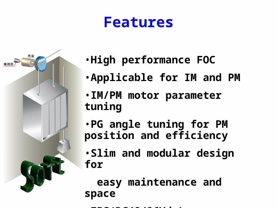
•High performance FOC
•Applicable for IM and PM
•IM/PM motor parameter tuning
•PG angle tuning for PM position and efficiency
•Slim and modular design for
easy maintenance and space
•EPS(DC48/96Vdc)
Features
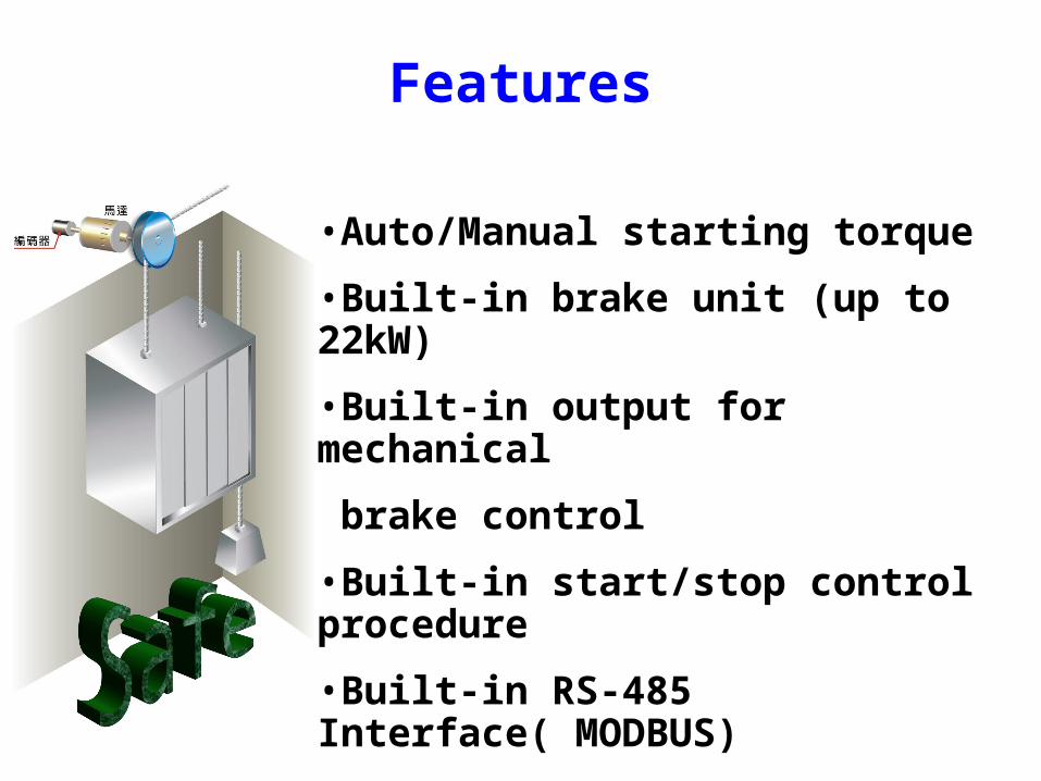
•Auto/Manual starting torque
•Built-in brake unit (up to 22kW)
•Built-in output for mechanical
brake control
•Built-in start/stop control procedure
•Built-in RS-485 Interface( MODBUS)
•Optional digital keypad
•Optional PG card
Features
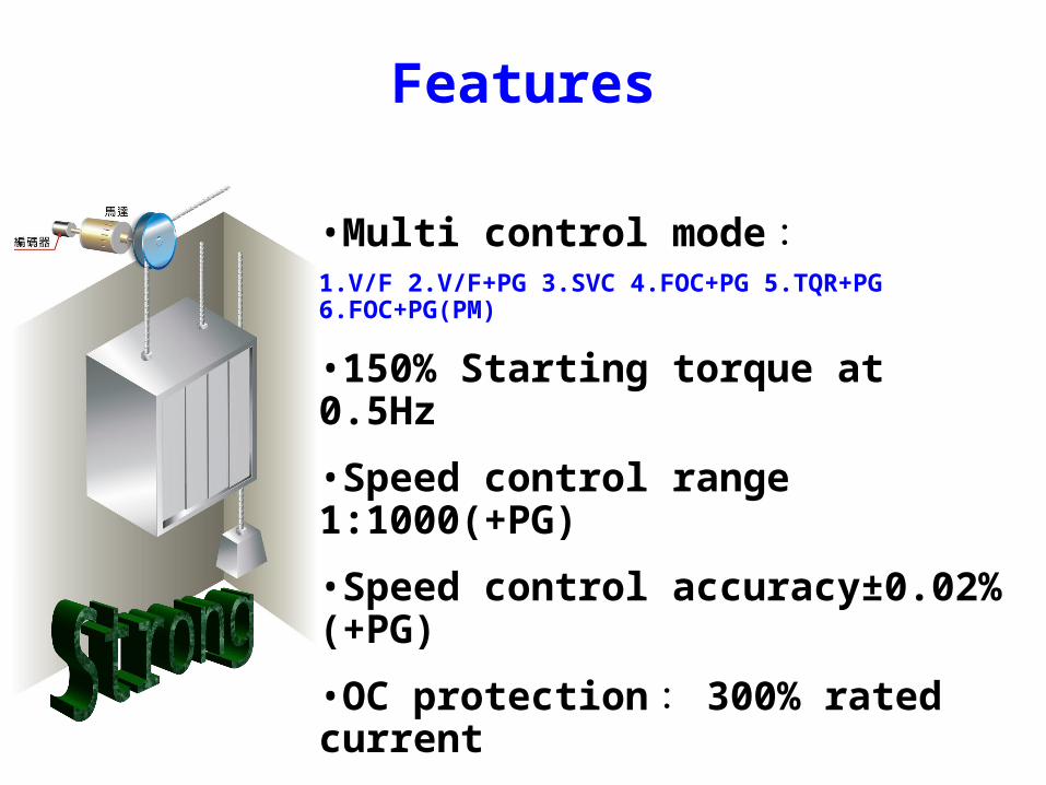
•Multi control mode :1.V/F 2.V/F+PG 3.SVC 4.FOC+PG 5.TQR+PG 6.FOC+PG(PM)
•150% Starting torque at 0.5Hz
•Speed control range 1:1000(+PG)
•Speed control accuracy±0.02%(+PG)
•OC protection : 300% rated current
•Analog resolution : 12bits

Flange and Wall mounting
Slim design
Movable installation

Fast capacitor change
Outline-Best design
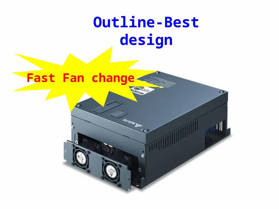
Fast Fan change
Outline-Best design

Modular design for control interface
Best design
Control boardControl board
I/O terminalI/O terminal
PG cardPG card

Optional PG card
EMVL-PGABLLine DriveABZ 、 UVW
EMVL-PGABOOpen collectorABZ
EMVL-PGH01HeidenhainSIN/COS
NEW
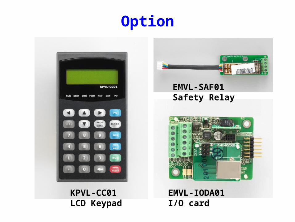
Option
EMVL-SAF01Safety Relay
EMVL-IODA01I/O card
KPVL-CC01LCD Keypad

Support for Emergency power supply
E P S /+
R /L 1
S /L 2
T /L 3
E P S /-
M I1 ~ 8
C O M
1
2
3
1
2
3
48V d c (2 30V S e r ie s )9 6 Vd c (46 0 V Ser ie s)
3~
B e fo re in p u t t in g e m e rg e n c y p o w e r, m a g n e t ic c o n ta c to r a n d a re O N a n dm a g n e t ic c o n ta c to r s h o u ld b e O F F.M a g n e t ic c o n ta c to r s h o u ld b e O Na fte r m a g n e t ic c o n ta c to r i s O N .B e fo re re m o v in g b a t te ry a n d tu rn m a g n e t ic c o n ta c to r to b e O N , m a g n e t ic c o n ta c to r a n d s h o u ld b eO F F.
T im in g d iag ra m o f M .C .( m a g n e t ic c o n ta c t o r )A C m o to r d r i v e
M a in p o w e r
To in p u t e m e rg e n c y p o w e r
2 5 0 V D C ( fo r 2 3 0 V s e r ie s )5 0 0 V D C ( fo r 4 6 0 V s e r ie s )
S p ec i f ic a t i o n s fo r 1 -p h a s e U P S a n d b a t te r y
1 -ph a s e U P S o r b a t te r y
Figu re 4 Ap ply to tw o bat te r ies w ith m ain b a ttery vo ltag e is lo w er than 28 0V d c
1 3
1 323
1
2
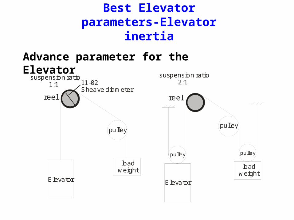
Best Elevator parameters-Elevator inertia
Advance parameter for the Elevator
reel reel
Elevator Elevator
loadweight load
weight
pulleypulley
pulley pulley
suspension ratio 1:1
suspension ratio 2:111-02
Sheave diameter
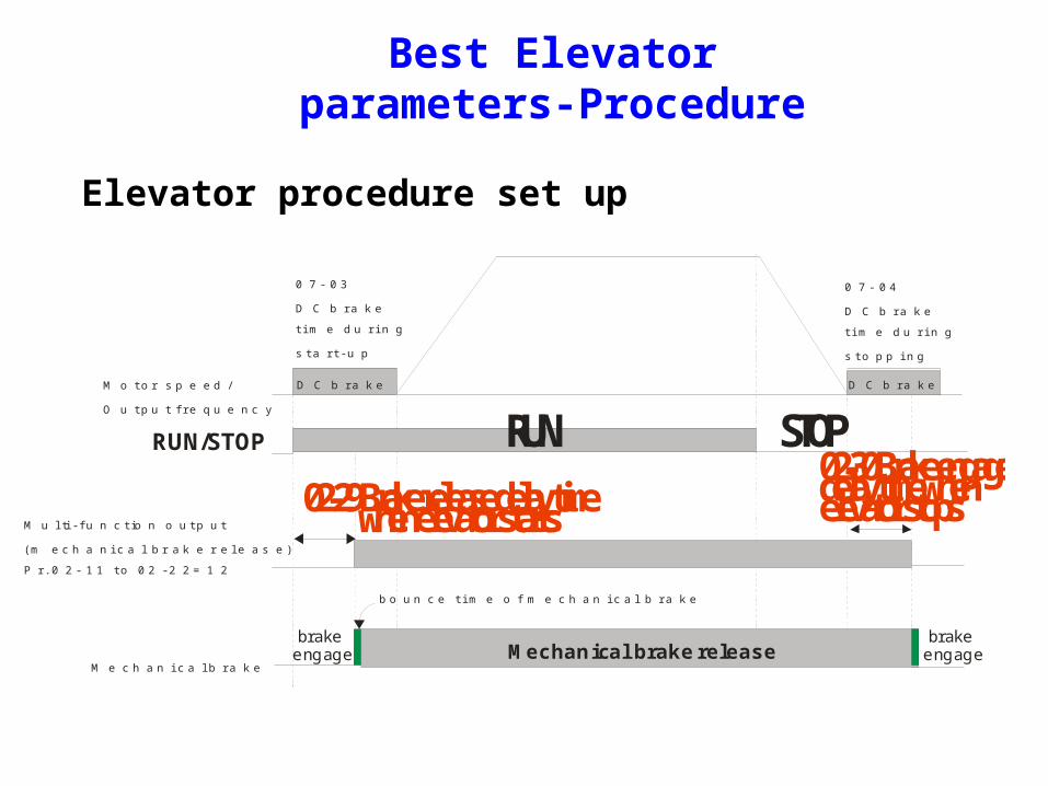
Elevator procedure set up
Best Elevator parameters-Procedure
M o t o r s p e e d /
O u t p u t f r e q u e n c y
0 7 - 0 3
D C b r a k e
t i m e d u r i n g
s t a r t - u p
0 7 - 0 4
D C b r a k e
t i m e d u r i n g
s t o p p i n g
M u l ti - f u n c t io n o u t p u t
( m e c h a n i c a l b r a k e r e l e a s e )
P r . 0 2 - 1 1 t o 0 2 - 2 2 = 1 2
M e c h a n i c a l b r a k e
b o u n c e t i m e o f m e c h a n i c a l b r a k e
RUN/STOP
02-29 Brake release delay time when elevator starts
RUN STOP02-30 Brake engage delay time whenelevator stops
D C b r a k e D C b r a k e
Mechanical brake release brake engage
brake engage

Best Elevator parameters-Start/Stop/Enable
MI4=3
MI3=2
MI2=1
MI1=40Enable dr ivefunction
0
1
1
0
1
0
0
0
0
07-03DC brake t ime duri ng start-up
07-04DC brake t ime during stopping
02-31Turn on delay of magnetic contactor between drive and motor
02-29 brake release delay t imewhen elevator starts
02-30 brake engage delay t imewhen elevator stops
02-32Turn off delay of magnetic contactor between drive and motor
01-24=S1
01-25=S2 01=26=S3
01-27=S4
01-30=S5
01-29Switch frequencyfor S3/S4 changesto S5
01-12accel. ti me
01-13decel. t ime
Start forwardrunning/startrev erse running
mult i-s tep speed1
mult i-s tep speed2
mult i-s tep speed3
frequencyoutput
DC brake
mult i-functionoutput =15Motor-c ontrol ledmagnetic c ontactoroutput
mult i-functionoutput=1operation indication
mult i-functionoutput=12mechanicalbrake release

Special
Reliability(FAN 5+ year/Cap10+ year)
Operate Temperature -10 ~ 45℃ ℃
Slim/Modular IM/PM
EncoderPosition control
Best Feature
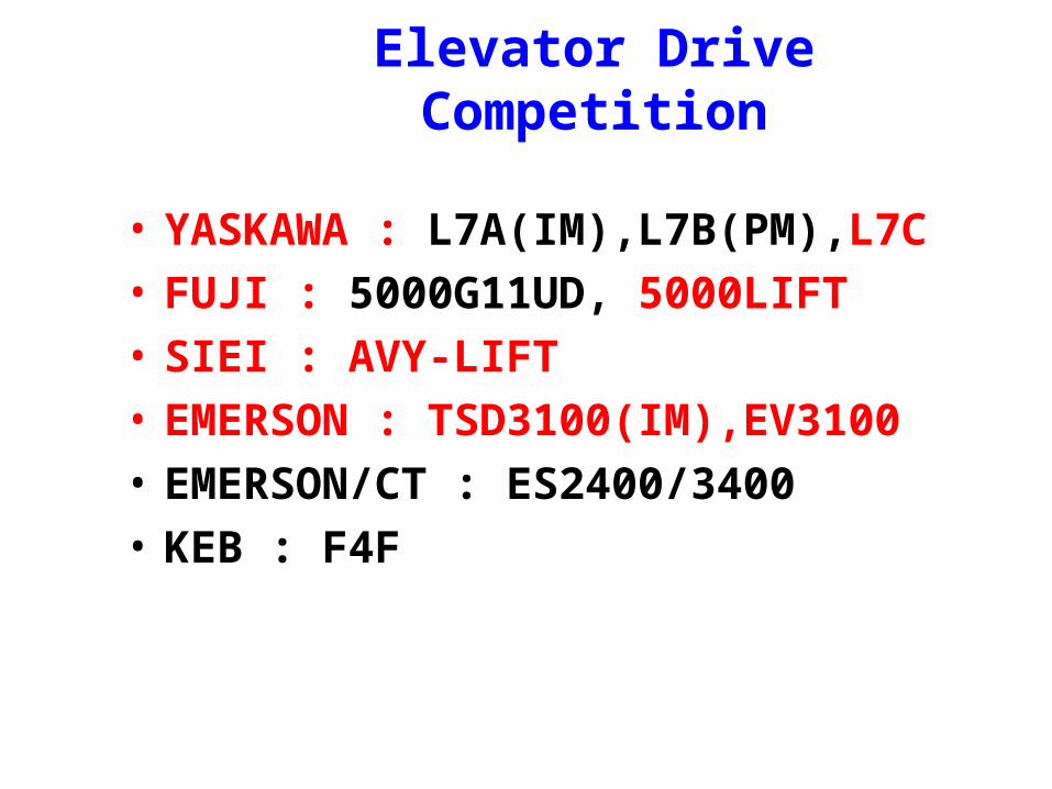
Elevator Drive Competition
• YASKAWA : L7A(IM),L7B(PM),L7C
• FUJI : 5000G11UD, 5000LIFT
• SIEI : AVY-LIFT
• EMERSON : TSD3100(IM),EV3100
• EMERSON/CT : ES2400/3400
• KEB : F4F

Power range of competition
Yaskawa L7C Emerson
EV3100
SIEI AVY-Lift
(firmwaredifference)
Fuji 5000G11UD2
220V 3.7kw~55kw N/A 2.2kW~30kW 3.7kW~55kW(N/A)
440V 3.7kw ~55kw 5.5kw~30kw 4kW~55kW 3.7kW~55kW
Delta VL-5.5kW~22kW Most of Elevator drive are between 7.5kW~22kWFor the Room-less is 15kW below
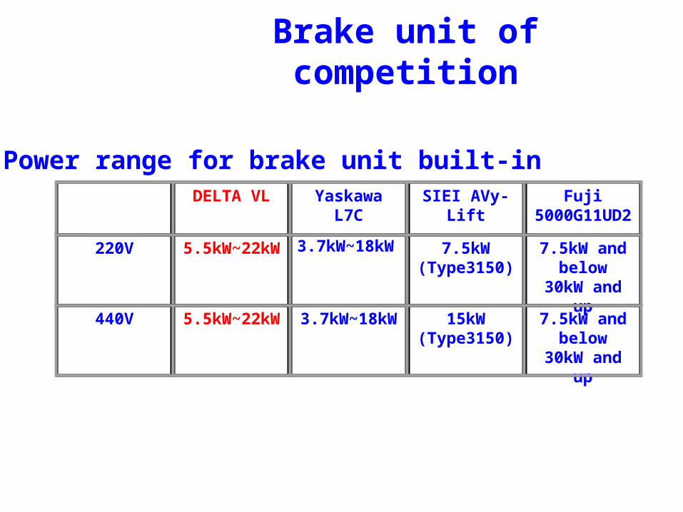
DELTA VL Yaskawa L7C
SIEI AVy-Lift Fuji 5000G11UD2
220V 5.5kW~22kW 3.7kW~18kW 7.5kW(Type3150)
7.5kW and below
30kW and up
440V 5.5kW~22kW 3.7kW~18kW 15kW(Type3150)
7.5kW and below
30kW and up
Brake unit of competition
Power range for brake unit built-in
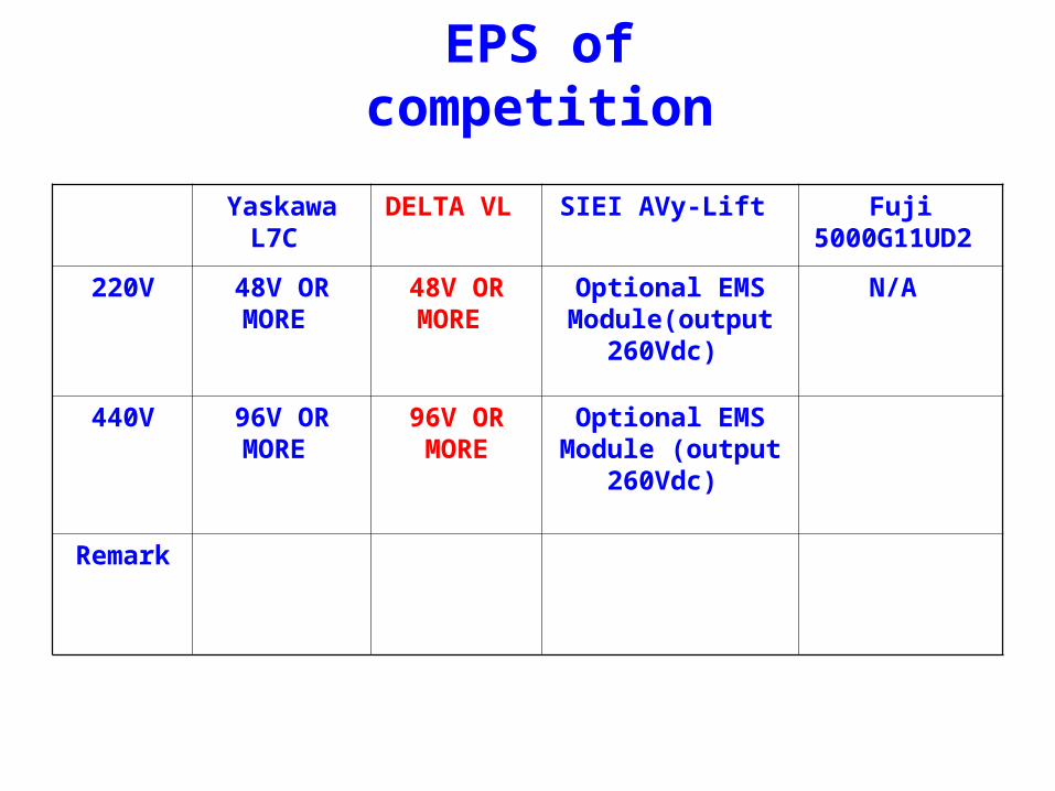
EPS of competition
Yaskawa L7C
DELTA VL SIEI AVy-Lift Fuji 5000G11UD2
220V 48V OR MORE
48V OR MORE
Optional EMS Module(output
260Vdc)
N/A
440V 96V OR MORE
96V OR MORE
Optional EMS Module (output
260Vdc)
Remark

TAIWAN 8000/YEAR
China 200000/YEAR
INDIA 50000/YEAR
USA 20000/YEAR
Estimation market size of Elevator
2008