version 3.0 february, 2012 craig e. l. stark, ph.d. · pdf fileversion 3.0 february, 2012...
TRANSCRIPT
Version 3.0February, 2012
Craig E. L. Stark, Ph.D.
Table of Contents......................................................................................................................................ACKNOWLEDGEMENTS 5
...................................................................................................................................................................LICENSE 6....................................................................................................................................................INTRODUCTION 7
...........................................................................................................................................WHAT’S NEW IN 3.0? 8............................................................................................................................................................FEATURES 10
......................................................................................................................................................MAIN SCREEN 15IMAGE WINDOW...................................................................................................................................................................... 15DISPLAY PANEL ....................................................................................................................................................................... 15CAPTURE PANEL ..................................................................................................................................................................... 17
...................................................................................................................................................................Camera Section 17.................................................................................................................................................................Exposure Section 17...................................................................................................................................................................Capture Section 18
STATUS BAR ............................................................................................................................................................................ 20CUSTOMIZATION OF THE INTERFACE ................................................................................................................................... 20
...............................................................................................................................................................Notes and History 21..................................................................................................................................................Camera-‐speci<ic Dialogs 21
.......................................................................................................................................................External Filter Wheel 22...............................................................................................................................................................................Pixel Stats 22
..........................................................................................................................................................Link to PHD Guiding 22............................................................................................................................................................................Macro Tool 23
.........................................................................................................................................CAPTURING IMAGES 24MONOCHROME VS. COLOR CAMERAS ................................................................................................................................... 24ONE-‐SHOT COLOR CAMERAS: SHOULD I CAPTURE RAW OR ................................................................................RGB? 25FILE FORMATS.......................................................................................................................................................................... 26CAMERA GAIN AND OFFSET................................................................................................................................................... 27
.............................................................................How should I set my gain and offset to set it and forget it? 27.............................................................................................................OVERVIEW OF IMAGE PROCESSING 29
........................................................................................Deciding on Bad Pixel Mapping vs. Dark Subtraction 29..........................................................................................................................Applying the darks, <lats, and biases 30
................................................................................................................................................Using Bad Pixel Mapping 31....................................Converting RAW images to Color and/or Pixel Squaring (aka Reconstruction) 32
........................................................................................................................................Normalize Images (optional) 32.............................................................................................................Grading and Removing Frames (optional) 33
1
........................................................................................................................................Stacking: Align and Combine 33...............................................................................................................................................................Crop off the edges 34
.............................................................................................................................................Remove the Skyglow Color 35..............................................................................................................................................................................Stretching 35
....................................................................................................IMAGE PRE-‐PROCESSING: THE DETAILS 37PRE-‐PROCESSING: THEORY.................................................................................................................................................... 37IMAGE SET PRE-‐PROCESSING TOOL ..................................................................................................................................... 38BAD PIXEL MAPPING .............................................................................................................................................................. 40
................................................................RECONSTRUCTION: DEMOSAIC-‐ING AND PIXEL SQUARING 42.........................................................................................................PREVIEWING AND GRADING IMAGES 44
.................................................................................................................................LRGB COLOR SYNTHESIS 45RGB MODE .............................................................................................................................................................................. 45LRGB: TRADITIONAL HSI MODE ........................................................................................................................................ 45LRGB: COLOR RATIO MODE................................................................................................................................................. 45
......................................................................IMAGE NORMALIZATION AND HISTOGRAM MATCHING 46.............................................................................................................................................STACKING IMAGES 47
OVERVIEW OF TRADITIONAL STAR-‐BASED ALIGNMENT ................................................................................................. 47COMBINATION METHODS ....................................................................................................................................................... 48
...........................................................................................................Averaging vs. Adding vs. Adaptive Stacking 48................................................................................................Standard Deviation Based Stacking (Sigma-‐clip) 49
ALIGN AND COMBINE OPTIONS............................................................................................................................................. 50...............................................................................................................................................Align and Combine: Fixed 50
..................................................................................................................................Align and Combine: Translation 50...................................................................................Align and Combine: Translation + Rotation (+ Scaling) 52
..................................................Drizzle alignment (Translation & Rotation + Resolution enhancement) 52.............................................Colors in Motion (Simultaneous translation align + Color reconstruction) 54
AUTOMATIC ALIGNMENT (NON-‐STELLAR .........................................................................................................................) 55........................................................................................................................................IMAGE ADJUSTMENT 57
DEMOSAIC’ING AND PIXEL SQUARING .................................................................................................................................. 57..................................................................................................................................................................Demosaic Image 57
..........................................................................................................................................................................Square B&W 57....................................................Reconstructing Images from One-‐shot Color Cameras and Line Filters 57
GEOMETRIC MANIPULATIONS................................................................................................................................................ 59..........................................................................................................................................................................................Crop 59
....................................................................................................................................................................Mirror / Rotate 59....................................................................................................................................................................................Binning 59.......................................................................................................................................................................................Resize 60
STRETCHING AND INTENSITY SCALING ................................................................................................................................ 60.....................................................................................................................................................Levels / Power Stretch 60
CURVES ..................................................................................................................................................................................... 62....................................................................................................................Digital Development Processing (DDP) 63
.................................................................................................................................................................................Zero Min 64...........................................................................................................................................Scale Intensity / Pixel Math 64
COLOR ADJUSTMENT ............................................................................................................................................................... 64.............................................................................................................................................................Adjust Color Offset 64..........................................................................................................................................................Adjust Color Scaling 65............................................................................................................................................................Auto Color Balance 65
.................................................................................................................................................................Hue / Saturation 65............................................................................................................................Discard Color and Convert to Color 65
LRGB COLOR SYNTHESIS TOOL ........................................................................................................................................... 65
2
SHARPENING, BLURRING, AND NOISE REDUCTION............................................................................................................ 65..........................................................................................................................Sharpening and Tighten Star Edges 66
.......................................................................................................................................................................Gaussian Blur 66.................................................................................................................................................................3x3 Pixel Median 67
................................................................................................................................Vertical Smoothing (deinterlace) 67NOISE REDUCTION .................................................................................................................................................................. 67
.....................................................................................................................................................OTHER TOOLS 70LAUNCH NEW INSTANCE........................................................................................................................................................ 70CHANGE LANGUAGE................................................................................................................................................................ 70IMAGE INFO AND FITS HEADER ........................................................................................................................................... 70DSS LOADER ........................................................................................................................................................................... 70MEASURE DISTANCE............................................................................................................................................................... 70CHECK / UPDATE LICENSE .................................................................................................................................................... 71
....................................................................................................................................SUPPORTED CAMERAS 72.........................................................................................................................................................................................SBIG 72
STARLIGHT XPRESS................................................................................................................................................................. 72CANON DIGIC II, III, & 4 DSLRS ........................................................................................................................................ 73
...........................................................................................................................................Color images and FITS/CR2 73......................................................................................................................................................................White balance 74
.....................................................................................................................................Long exposures / bulb triggers 74.......................................................................................................................................................................Mirror lockup 75
..........................................................................................................................................Mode dials and lens settings 75.......................................................................................................................................Troubleshooting Connections 76
ASCOM CAMERAS .................................................................................................................................................................. 76SAC7 AND LONG EXPOSURE WEBCAMS ............................................................................................................................. 77CAMERA ADVANCED PANEL .................................................................................................................................................. 77
....................................................................................................................................TAKING GOOD IMAGES 79YOUR TELESCOPE.................................................................................................................................................................... 79YOUR MOUNT .......................................................................................................................................................................... 80
..................................................................................................................................................................Polar Alignment 80............................................................................................................................................Periodic Error and Guiding 80
FOCUS........................................................................................................................................................................................ 81EXPOSURE SETTINGS............................................................................................................................................................... 82Rule #1: Use the Histogram to keep your background above the <loor and bright bits below the
......................................................................................................................................................................................ceiling. 82..........................................................................................................................................Rule #2: Take lots of images 83
..........................................................................................................................Rule #3: Don't over-‐tax your mount 83..........................................................................................................................................What do gain and offset do? 83
....................................................................................................Gain's downside: Bit depth and dynamic range 84How do manufacturers determine gain and offset for cameras that don't allow the user to adjust
........................................................................................................................................................................................them? 84...............................................................................................................................MENU QUICK REFERENCE 86
FILE MENU ............................................................................................................................................................................... 86EDIT MENU .............................................................................................................................................................................. 86BATCH MENU (SEE ALSO THE PRE-‐PROCESSING SECTION .............................................................................................) 87IMAGE MENU (SEE ALSO THE IMAGE ADJUSTMENT SECTION .........................................................................................) 87VIEW MENU ............................................................................................................................................................................. 89HELP MENU ............................................................................................................................................................................. 89
.....................................................................................................................................................PREFERENCES 90CAPTURE................................................................................................................................................................................... 90OUTPUT .................................................................................................................................................................................... 91
3
PROCESSING ............................................................................................................................................................................. 91COLORS ..................................................................................................................................................................................... 92MISC .......................................................................................................................................................................................... 92
.................................................................................................................................................................SCRIPTS 93SCRIPT EDITOR ........................................................................................................................................................................ 93FULL COMMAND LIST ............................................................................................................................................................. 94
..............................................................................................................................................Capture Setup Commands 94............................................................................................................................................................Control Commands 95
......................................................................................................................Advanced Camera Control Commands 96
All text and images Copyright Craig Stark, Stark Labs 2005-2012Last updated February, 2012
4
1 AcknowledgementsThe author would like to extend his heartfelt thanks to several individuals who have helped in the creation of Nebulosity. In particular, I would like to thank Michael Garvin, Chuck Kimball, Sean Prange, and Dave Schmenck for all their perennial help. Several individuals worked very hard in translating Nebulosity into other languages and I am very grateful for the help of Christoph Bosshard (German), Denis Bram (French), Michele Palama (Italian), Rodolphe Pineau (French), and Ferry Zijp-Herzberg (Dutch).
I would also like to acknowledge the fine wxWidgets cross-platform GUI library used extensively here. Without it, I would not have written Nebulosity. I would like to acknowledge use of the FreeImage, LibRAW, and CFITSIO libraries for image input and output. In addition, note that the noise reduction software GREYCstoration and the automatic alignment software ANTS, are included as binary applications bundled with and called from Nebulosity.
5
2 LicenseNebulosity ("Software") and all of its documentation are Copyright 2005-2012 Craig Stark (Stark Labs). This is commercial software and is not freeware. Please read the following "Fair" End User License Agreement carefully.
1. We grant you one license to install and use this software on one computer at a time. If you do not agree to the following terms of this license, please uninstall and remove all copies. If you have purchased this software and it was not included with a camera purchase, return the product within 10 days of your purchase for a full refund.2. You may install and use the software on another computer, but the software should not be in use on more than one computer at a time unless you purchase additional licenses (e.g., a laptop used for image collection and a desktop used for subsequent image processing). You may make back-up copies of the software for archival purposes. You may permanently transfer your license to use the software to another party who will be bound by this agreement, provided you do not retain any copies of the software.3. The software is protected by the copyright laws of the U.S. and other countries, and we retain all intellectual property rights in the software. You may not separately publish, sell, market, distribute, lend, lease, rent, or sublicense the software. However, this license is not to be construed as prohibiting or limiting any fair use sanctioned by copyright law.
LIMITED WARRANTY4. We warrant that the software will provide the features and functions generally described in the product specification on our website when you purchased it and in the product documentation. Media on which the Software is furnished, if any, will be free from defects in materials and workmanship.5. We have taken all reasonable steps to keep the software free of viruses, spyware, "back door" entrances, or any other harmful code. We will not track or collect any information about you, your data, or your use of the software except as you specifically authorize. We will not intentionally deprive you of your ability to use any features of the software or access to your data.6. We do not warrant that the software or your ability to use it will be uninterrupted or error-free. To the extent permitted by applicable law, we disclaim any implied warranty of merchantability or fitness for a particular purpose.
LIMITATIONS ON LIABILITY7. Your exclusive remedy under the above limited warranty shall be, at our option, either a full refund of the purchase price (if purchased separately from a camera) or correction of the defective software or media. To the fullest extent permitted by applicable law, we disclaim all liability for indirect or consequential damages that arise under this license agreement. Nothing in this agreement limits our liability to you in the event of death or personal injury resulting from gross negligence, fraud, or knowing misrepresentation on our part.
GENERAL PROVISIONS8. If any part of this agreement is found to be invalid or unenforceable, the remaining terms will stay in effect. This agreement does not prejudice the statutory rights of any party dealing as a consumer.9. This agreement will be governed by the laws, including Article 2 of the Uniform Commercial Code, of the state in which you reside. If your state has enacted the Uniform Computer Information Transactions Act (UCITA) or substantially similar law, said statute shall not govern any aspect of this agreement and instead the law as it existed prior to such enactment shall govern.10. This agreement does not supersede any express warranties we made to you. Any modification to this agreement must be agreed to in writing by both parties.
Additional license information for included executables is provided in the installer.
6
3 Introduc6onWelcome to Nebulosity 3! Nebulosity began in 2005 with the goal of providing a means of easily and efficiently capturing images of DSO objects using your CCD camera. It has grown considerably since then, but has remained true to those goals. It is designed to be a powerful, but simple to use capture and processing application for your CCD or DSLR camera. Its goal is to suit people ranging from the novice imager who wants to create his or her first images and the advanced imager who wants a convenient, flexible capture application for use in the field. As such, an emphasis has been placed on easy access to commonly-used camera controls, as nobody wants to navigate through many menus in order to simply capture a series of images. There is a lot of power under the hood, but what’s presented on the surface should be easy to use.
An emphasis has also been placed on compatibility with other applications. For many imagers, the tools provided here will be well-suited to produce images that are ready to be touched up in a graphics editing package (e.g., Adobe Photoshop). The tools provided are the tools most of us want and need to make great images. For more advanced imagers who already use more sophisticated astronomical image manipulation software, Nebulosity might serve as a suitable capture application and provide a set of key processing tools. Nebulosity supports a wide range of output formats, including various FITS formats and other 16-bit per color formats, so that your images can be easily imported into whatever software you use.
What Nebulosity is not designed to do is to be an all-inclusive, general-purpose, observatory control and image capture / analysis package. There are several of these on the market already and all are fine packages. All are very large, place more substantial demands on your computer, and, by virtue of being large and all-inclusive, do not typically present a simple, clean, interface for basic image capture control. The author of Nebulosity routinely stands in cold, dark fields with a laptop and a camera taking pictures. Under these situations, when gloves must be removed to operate the computer, simple, dedicated user interfaces are exceptionally welcome.
That said, the author is also a stickler for power and accuracy. You get quite a few "serious" tools in Nebulosity. The ones you get are purpose-built - tools that you will want for processing raw DSO images into beautiful pictures.
One more thing - I’m also a stickler for “fair use” in licensing. Your Nebulosity 3 license is not tied to one machine or even one operating system. Feel free to use it on a laptop for image capture and a desktop for processing. Feel free also to upgrade to any new release in the v3 series.
7
4 What’s New in 3.0?Version 3 of Nebulosity has brought a number of new features and a lot of work under the hood to speed up processing, lighten the load on your computer, and be more stable than ever before. An emphasis has been placed on enhancing usability and on improving existing features to make them both more powerful and more approachable in addition to adding new features. It’s easy for software to become bloated and unwieldy. A goal of Version 3 was to prevent this and to lay a foundation for more growth to come. Since Nebulosity 2.5 we have:
• The ability to run more than one instance of Nebulosity via a new Launch another instance entry in the File menu. This will launch another instance of Nebulosity to let you run more than one camera or to let you work on several images or projects at once.
• Creating scripts was not very user-friendly in previous versions. These are very powerful ways to automate image capture and now there is a new script creation tool that lets you write scripts far more easily. Just select commands from the list and double-click to add them to the script or choose from a set of predefined scripts. If you change the parameter values before double-clicking, the command and parameter will go in there. If not, just edit the script being formed to fill in the desired values. No more having to remember all the commands! Also, if you leave this window with a script in place that you're working on, it will remember it for next time (so long as you don't quit Neb).
• In addition to the new tool, we have some new script commands and revisions to existing commands to make them easier to use.
o Times (like exposure durations) are now in seconds with fractions allowed. So, if you want 10.5 seconds you can say "SetDuration 10.5". You should not say the old "SetDuration 10500" (the old msec format). This parallels the main UI. You can also use an "m" in here to denote minutes. For example 'SetDuration 2.5m' would be 2 minutes, 30 seconds. '2m30' would also be this.
o SetTEC command added to set the TEC regulation temperature (e.g., "SetTEC -10.0")
o SetPHDDither command added to control the dither level on the PHD link. 0=none, …, 5=extreme
• Ever want to apply the same processing to another image or set of images? There is now a new Macro tool in place to do just this. Copy/paste from your history (or triple-click, Append to Macro in History or just write it manually) and build up a processing sequence to run on other images.
• Numerous image adjustment tools and internal bits significantly sped up through use of all available processors on your machine and more efficient code. You should notice that pre-processing and image adjustment is a more responsive, especially on big images and if your computer has several processing cores. In addition, the memory load for color images has been
8
reduced considerably.
• Extensive support for internationalization and foreign language support. Virtually the entire user interface is now setup for other languages. Currently, we have Dutch, French, German, and Italian!
• New debayer / demosaic algorithms have been added (a setting in Preferences controls which one is used). Two simple ones (color binning and bilinear), PPG (patterned pixel grouping by Alain Desboilles), and AHD (Adaptive Homogeneity-Directed by Keigo Hirakawa, Thomas Parks, and Paul Lee) are now added to the VNG (variable number of gradients by Ting Chen) previously available.
• Sliders work most of the time for setting values while manipulating images, but sometimes you want to specify the value exactly. Now, simply double-click on the value and you can specify the image manipulation parameters directly.
• Ever want to force an image to be “color” even if it’s mono (e.g., to use in pre-processing color images)? We now have a convert to color tool to do just this.
• What’s an update without updates to the supported camera list?
o "Atik 3xx,4000,10000" entry changed to "Atik Universal" (Windows).
o The original "ASCOM Camera" has been removed (early-bound interface that is no longer used in ASCOM as of v5 and v6) and the previous "ASCOMLate Camera" renamed "ASCOM Camera" (Windows).
o Canon 600D support and updates for T3 and T3i
o The QSI 500 cameras on the Mac shifted to open-source based libftdi for better stability with the new 600 series cameras. Both have been renamed “QSI 500/600”
o SBIG has been updated to 4r73B7-based driver for STF-8300 support
• The main window’s user-interface has gotten a facelift and a number of the colors are now customizable (see Preferences). In addition, a 10% zoom option is in place and zooming in and out is faster and more predictable.
• For Mac users, one change is that the PPC processors are no longer supported and neither is OS X 10.4 (Tiger). You must be on an Intel, 64-bit capable processor running 10.5 (Leopard) or later. 32-bit Intel processors (e.g., the original Core Duos) will work for most, but not all features (e.g., auto-align non-stellar).
9
5 Features• Cross-platform support
o Mac OS X 10.5 - 10.7 (Intel)o Windows XP, Vista, and 7o Same license code works on both platforms and all functionality is
available across platforms (Note, not all cameras are supported on all platforms for image capture.)
• Simple, but powerful interface
o All basic controls are present on the main screen. No need to navigate through lots of menus during an imaging session. Nebulosity was designed to be easily operated in the field by someone who actually operates it in an actual field.
o Interface can be customized to show, arrange, or hide tools to suit your needs.
o Ability to have multiple instances of Nebulosity running for processing different images or controlling different cameras.
o Support for multiple languages (currently, English, Dutch, French, German, and Italian)
o By default, all displays are auto-scaled. Any scaling (including inverted) of the data onto the display possible using easy sliders.
o Histogram gives a quick view of how much of the valid data range is being used during each capture.
o Pixel statistics / area statistics pop-up window for real-time readouto Zoom button lets you rescale the displayed image quickly. o Image pan mode (shift key)o Unlimited undo/redo (0, 3, or unlimited levels of undo). o Small clock to show local time, UTC, GMST, local sidereal, Polaris RA, or
current CCD temperature • Capture control
o All basic capture parameters present on main screen. Duration of exposure, number of exposures per captured series, delay between captures, name of series, camera gain and camera offset all in one simple panel.
o 1x1 - 4x4 binning (depending on camera) and fast-readout modes supported
o Quick Preview button captures one frame with current settings and displays it on the screen without saving. Helps in focus, composition, and tuning of capture parameters.
o Frame and Focus mode: Loops a quick, binned image to assist in rapid initial focus and framing (crosshairs can be enabled or disabled via Preferences).
o Fine Focus mode with HDR focus metric: Loops a very quick image around a selected star in full resolution and provides running statistics (and linegraphs of the history of the statistics) to assist in fine-tuning focus.
10
o Support for using LiveView during Frame and Focus and/or Fine Focus on Canon DSLRs supporting LiveView.
o Capture one-shot color in RAW CCD format or reconstruct color on the fly – your choice.
o Capture status able to be shown in large red display for easy viewing when away from computer.
o Link to PHD Guiding to enable pausing guiding during main image download and to dither location of images.
o Focus information available to other programs (see Preferences, Save Fine Focus info and CaptureSingle script command).
o Control of both on-board and external filter wheels both in the main user-interface (Tools) and automated via scripts
• Multiple file formats supported o Read virtually any FITS file to process images from virtually any camera
(RGB color, black and white, compressed or uncompressed, any bit depth)
o Load and process data from FITS, PNG, PPM/PNM/PGM, TIFF, BMP, JPEG and just about any DSLR “RAW” format.
o Captured data saved in FITS as 16-bits (0-65,535) per color channel, 32-bit floating point, or in 15-bits (0-32767) per color channel.
o One-shot color data captures may be saved in RAW CCD format or as reconstructed full-color images in an RGB FITS format (Maxim / AstroArt style or ImagesPlus style) or 3 separate FITS files (the latter only for capture and subsequent use in other programs).
o Captured data saved in either lossless compressed FITS according to the FITS standard or uncompressed FITS
o These same save formats available for any loaded image, making Nebulosity serve to convert between many FITS formats (just select your output format using the settings on the Preferences menu).
o Save current displayed image in BMP or JPG format (24-bit color) as displayed
o Save current image in 16 bit/color (48-bit color) uncompressed TIFF, compressed TIFF, or PNG (compressed) format
o Load 8/24 bit PNG, TIFF, JPG, and BMP (scaled to 16/48-bit) or 16/48-bit PNG and TIFF.
o Batch convert from FITS to 16/48-bit PNG or compressed TIFF o Batch convert from DSLR RAW and standard image formats (PNG, TIFF,
JPG, and BMP) to FITS • Extensive camera support (capture - Windows-only unless noted)
o Apogee Altao Atik 16/16IC/16HR series / Artemis 429/285 cameraso Atik “Universal” (3xx, 4xx, 4000, 11000, etc)o ASCOM 5 and ASCOM 6 compliant cameraso Canon DIGIC II, III, and 4 DSLRs (Windows and OS X): EOS 1100D/T3,
1000D/Rebel XS, 450D/Rebel XSi, 400D/Digital Rebel XTi, 500D/T1i, 550D/T2i, 600D/T3i, 350D/Digital Rebel XT, 60D, 50D, 40D, 30D, 20D/
11
20Da, 5D Mark II, 5D, 7D, 1D Mark IIV, 1D Mark III, 1D Mark II N, 1D Mark II, 1Ds Mark III and 1Ds Mark II. Captures are to FITS files with pure Bayer-matrix data extracted on the fly (or ultra-fast color JPEGs - your choice). Bulb-mode exposures via ShoeString DSUSB adapter, serial port adapters, or parallel port adapters.
o CCD Labs Q8-HR and QHY8 (Windows & Intel/Leopard Macs)o CCD Labs Q285M / QHY2Pro o FLIo Fishcamp Starfish (Windows and OS X) o Meade DSI, DSI Pro, DSI II, and DSI II Pro (Windows and OS X). o Moriavian G2/G3 (v3 or higher firmware)o Opticstar DS-335 and DS-335 ICE o Opticstar DS-336Co Opticstar DS-142M and DS-142Co Opticstar DS-145M and DS-145Co Opticstar PL-130M and PL-130C o Orion StarShoot Deep-Space Color Imager (original - others via ASCOM)o QSI 500/600 series (Windows and Mac)o QHY 8, 8Pro, and 9 (and CCD Labs variants)o SAC10 o SAC7 / SC1 long-exposure modified webcams / Atik 1&2 - all via the
either a parallel port or via the ShoeString LXUSB adapter for all-USB (no parallel port) long-exposure imaging.
o SBIG (Windows and OS X) o Starlight Xpress SXV / SXVF / SXVR USB cameras (Windows and OS X) o Simulated camera (Windows and OS X) o Virtually any camera's images can be processed in Nebulosity.
• Internal calculations o All data stored internally in 32-bit floating point per color channel. For
B&W or RAW images, this equates to 32-bits and for color images, this equates to 96-bits in all math routines. You will never have overflow (saturation) or overflow or quantization issues as a result.
o Critical math routines computed in double-precision (64-bit per channel) floating point.
o Routines are optimized for high-speed operation and most will make full use of however many processing cores you have on your machine.
• Image alignment, stacking and pre-processing o Dark / flat / and bias frame pre-processing tool to let you pre-process
multiple sets of B&W, RAW one-shot color, or color images. o Create and apply Bad Pixel Maps as an alternative way of removing hot
pixels. o Align a series of images using simple translation (for equatorially mounted
telescopes) or using sub-pixel level accuracy and translation + rotation and (optional) scaling (equatorial or alt-az telescopes)
o Drizzle alignment and resolution enhancement for either equatorial (translation only) or alt-az (translation + rotation).
12
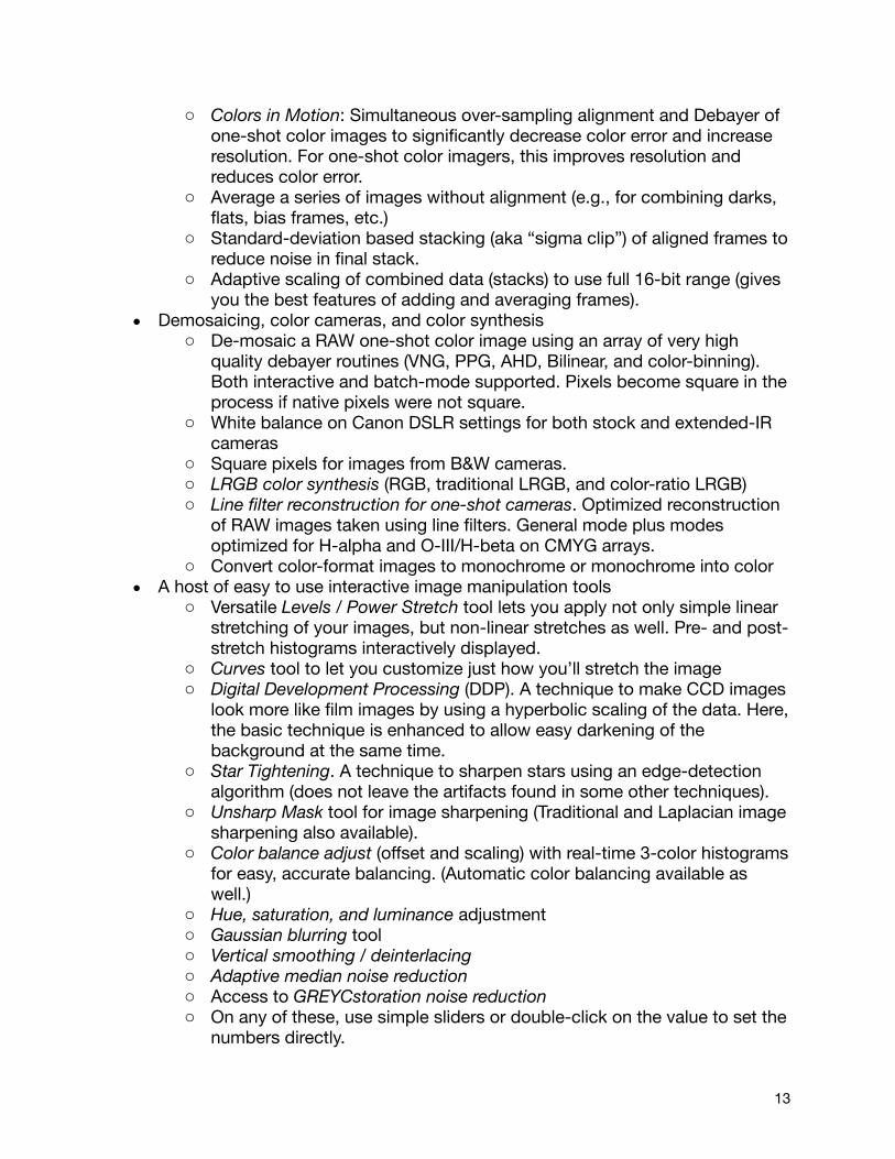
o Colors in Motion: Simultaneous over-sampling alignment and Debayer of one-shot color images to significantly decrease color error and increase resolution. For one-shot color imagers, this improves resolution and reduces color error.
o Average a series of images without alignment (e.g., for combining darks, flats, bias frames, etc.)
o Standard-deviation based stacking (aka “sigma clip”) of aligned frames to reduce noise in final stack.
o Adaptive scaling of combined data (stacks) to use full 16-bit range (gives you the best features of adding and averaging frames).
• Demosaicing, color cameras, and color synthesiso De-mosaic a RAW one-shot color image using an array of very high
quality debayer routines (VNG, PPG, AHD, Bilinear, and color-binning). Both interactive and batch-mode supported. Pixels become square in the process if native pixels were not square.
o White balance on Canon DSLR settings for both stock and extended-IR cameras
o Square pixels for images from B&W cameras. o LRGB color synthesis (RGB, traditional LRGB, and color-ratio LRGB) o Line filter reconstruction for one-shot cameras. Optimized reconstruction
of RAW images taken using line filters. General mode plus modes optimized for H-alpha and O-III/H-beta on CMYG arrays.
o Convert color-format images to monochrome or monochrome into color• A host of easy to use interactive image manipulation tools
o Versatile Levels / Power Stretch tool lets you apply not only simple linear stretching of your images, but non-linear stretches as well. Pre- and post- stretch histograms interactively displayed.
o Curves tool to let you customize just how you’ll stretch the imageo Digital Development Processing (DDP). A technique to make CCD images
look more like film images by using a hyperbolic scaling of the data. Here, the basic technique is enhanced to allow easy darkening of the background at the same time.
o Star Tightening. A technique to sharpen stars using an edge-detection algorithm (does not leave the artifacts found in some other techniques).
o Unsharp Mask tool for image sharpening (Traditional and Laplacian image sharpening also available).
o Color balance adjust (offset and scaling) with real-time 3-color histograms for easy, accurate balancing. (Automatic color balancing available as well.)
o Hue, saturation, and luminance adjustment o Gaussian blurring tool o Vertical smoothing / deinterlacing o Adaptive median noise reduction o Access to GREYCstoration noise reductiono On any of these, use simple sliders or double-click on the value to set the
numbers directly.
13
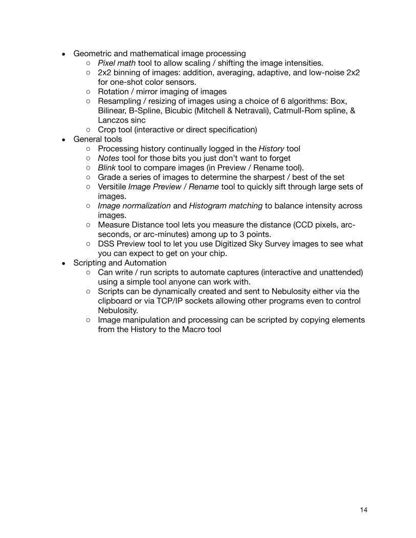
• Geometric and mathematical image processingo Pixel math tool to allow scaling / shifting the image intensities. o 2x2 binning of images: addition, averaging, adaptive, and low-noise 2x2
for one-shot color sensors.o Rotation / mirror imaging of images o Resampling / resizing of images using a choice of 6 algorithms: Box,
Bilinear, B-Spline, Bicubic (Mitchell & Netravali), Catmull-Rom spline, & Lanczos sinc
o Crop tool (interactive or direct specification)• General tools
o Processing history continually logged in the History toolo Notes tool for those bits you just don’t want to forgeto Blink tool to compare images (in Preview / Rename tool).o Grade a series of images to determine the sharpest / best of the set o Versitile Image Preview / Rename tool to quickly sift through large sets of
images. o Image normalization and Histogram matching to balance intensity across
images.o Measure Distance tool lets you measure the distance (CCD pixels, arc-
seconds, or arc-minutes) among up to 3 points. o DSS Preview tool to let you use Digitized Sky Survey images to see what
you can expect to get on your chip. • Scripting and Automation
o Can write / run scripts to automate captures (interactive and unattended) using a simple tool anyone can work with.
o Scripts can be dynamically created and sent to Nebulosity either via the clipboard or via TCP/IP sockets allowing other programs even to control Nebulosity.
o Image manipulation and processing can be scripted by copying elements from the History to the Macro tool
14

6 Main ScreenWhen you open Nebulosity, you are presented with a screen that looks like this (Windows version is similar):
It has 4 main sections: 1. Image Window (Large black area)2. Display Panel (Top portion on the right)3. Capture Panel (Middle right)4. Status Bar (Bottom)
6.1 Image WindowThe image window is where your images will be displayed. It starts off at a default size (optimized for 1024x768 displays), but is easily resized by simply resizing or maximizing Nebulosity itself. If an image is too big to fit into the window, the scrollbars will allow you to navigate around the image. Alternatively, the Zoom button, located in the Display panel, will resize the image to help make it fit your screen.
6.2 Display PanelHere, you have several controls that affect how the image is displayed in the Image Window. Keep in mind that your data are often in 16-bit (or 48-bit aka 16-bit/color) format. That
Tip: Want to slide around in an image quickly? Try holding down the shift key and dragging around in the image to do an accelerated “pan” through the image.
15

means that you can have 65,536 shades of grey in the image. But, your monitor can most likely only display about 256 shades of grey (24-bit color). Thus, the data need to be scaled to display well on your screen. That's the purpose of the first three controls here.
These are the B and W sliders, and the Auto scale checkbox. The B and W sliders set the level in your data to assign to black and white respectively. Slide the B slider to the right and your image gets darker. You've told Nebulosity that a higher image intensity equals black, meaning more of your data should be dark. Slide it to the left and the image gets brighter. Likewise, slide the W slider left and the image gets brighter as more of your data should be white. Put them closer and you have a higher contrast image. Put them further apart and you have a lower contrast image. Flip sides (white below black) and you'll invert the image. If you don't want to mess with any of this or if the image gets way out of whack, select Auto scale (it's set by default). The Auto scale checkbox tries to set the B and W sliders automatically by using data from the Histogram.
If you want to manually set specific values for B and W, you can enter them in the fields provided (that also read out the current values of the sliders). To make the changes take effect, press Enter inside the edit box.
Below the sliders is a Histogram display. When you first start Nebulosity it is black, but if you load an image or capture an image (use the Camera Simulator if you don't have one) you'll see a red display in this window. This box intentionally lines up with the sliders, for the left of the box corresponds to intensities near zero in your image and the right corresponds to intensities near the maximum (65,535 for 16-bits) in your image. So, if you see a small area of red on the left side of the histogram and you're not seeing anything on the screen, it means that you have a faint signal in the image. Slide the W slider to the left to come near that small area of red and you'll see your faint image.
The Histogram is a very powerful tool in image capturing, for it tells you a lot about your image. Are all of the data far to the left? If so, your entire image is faint and you should increase your exposure or gain if possible (see below). Do you see a nice curve that trials off to the right just before you get to the edge of the Histogram? If so, you've got a nice exposure and are making the most of your data. Do you see that instead of trailing off smoothly near the right edge, the curve ends abruptly at the right edge? If so, you're saturating a lot of the pixels in your image and should likely use a shorter exposure or less gain. Are you cutting of hard on the left edge? If so, use more gain, more offset, or a greater exposure duration.
Keep in mind that these tools only affect the way the image is displayed. They do not affect the actual data. If you save the image, adjust the sliders or zoom control and save it again under a new name, you'll have two identical copies of the same data. (There is one exception to this rule. The Save BMP As Displayed uses the values in the sliders to help get your data from 48-bits into 24-bits)
16
Finally, the panel has the Zoom button (marked "100%" by default). Repeated clicks on the Zoom button will cycle through several zoom modes (20%, 25%, 33%, 50%, 100%, 200%, & 400%) to get a better view of your image. Next to this, you'll see + and - buttons that let you zoom in and out respectively. Note again, this only affects how you see your image, it does not change the underlying image itself.
For a more detailed inspection of your image, try activating the Pixel Stats pop-up window (under the Image menu).
6.3 Capture PanelThe main Capture Panel has several sub-sections. At the top, we have an area that controls connection to the camera and advanced settings for the camera. Below this, we have an area that lets you control details of the exposure and below this we have a number of buttons that let you take various kinds of exposures.
6.3.1 Camera Sec5onThe Camera section contains a pull-down to select your camera model. When you pull down your camera model, Nebulosity attempts to connect to the camera. Success of failure will be noted in the left-hand panel of the Status Bar.
If you're new to CCD imaging and don't have a camera yet or want to explore some of Nebulosity without attaching your camera, a Camera Simulator is provided as one of the camera choices. The camera is always aimed at the same patch of sky (that happens to have 20 stars of different brightness) but the mount isn't perfect, so you'll notice the stars move a bit from image to image. The camera has noise, and responds to all the controls in the Exposure Panel, letting you get a feel for what to expect and how to use the program.Here, you will also find an Advanced tab. Nebulosity picks default values of a number of camera options that are optimal for most DSO imaging. However, if you want to select any of these yourself, you can do so in the dialog box that appears when you click this button.
6.3.2 Exposure Sec5onHere, you have controls for all basic exposure options.
• Duration: How long per image (in seconds) should the exposure be? Note, fractions like 1.5 allowed.
• Gain (optional): Some cameras let you adjust the gain and offset of the A/D converter. This entry controls how much CCD amplifier gain should be used during A/D conversion. (Think of gain as a volume knob for the signal coming off the CCD). Numbers range from 0-63.
You can use Ctrl + and Ctrl - (or Cmd + and Cmd - to zoom in and out.
Too many cameras listed there to sort through each time? In the Edit menu, you’ll find an option to De-select cameras and remove them from the list. Don’t worry - you can always add them back in later.
17
• Offset (optional): What offset should be added to the signal during A/D conversion? (The offset adds signal into every pixel to help you keep the pixels from having zero values anywhere). Numbers range from 0-255. (See Automatic Offset on p. 16)
• # Exposures: How many images do you want to take? • Time lapse: How much time (seconds) should be inserted between each
image?
Most of these are fairly self-explanatory, but Gain and Offset deserve a bit of attention. They get this in the Section Taking Good Images. For now, you can leave them at their default values.
The Duration and Time Lapse entries allow you to specify the exposure duration in seconds, but fractions are allowed. So, if you want an exposure of a half a second, simply enter “0.5”. Remember that a millisecond is a thousandth of a second (0.001). In addition to allowing you to enter the time directly, the Duration control lets you pull down any of a number of common times. The word “Duration” is actually a button. Click and hold on it and a list of common times will appear that you can quickly select without having to type numbers in while in the dark.
6.3.3 Capture Sec5onIn this panel, you'll find the Preview button. This button takes a single image at whatever duration, gain, and offset you've specified and shows it on the screen. It does not save the image. This lets you fine-tune the composition of your image and hone in on correct focus of your telescope. It also lets you determine the optimal duration, gain, and offset. (Use the handy Frame and Focus button for rough focus and composition).
There are three controls used in capturing a Series. A text entry box near the bottom lets you set the default Name for the series and a button lets you select the Directory the data will be saved in. Finally, at the top of the panel is the Capture Series button. This starts the sequence acquisition process. For example, if you've setup for 10 exposures of 20 seconds to be stored in My Documents\Nebulosity\August_20_2011 and called M51, Nebulosity will loop and take all 10 exposures. The first will be called M51_1.fit, the second M51_2.fit, etc. At the end
Want to set your CCD’s TEC? The Advanced button and an entry in Preferences let you do this (as does any camera-specific tool). Want to know the current temperature? In Preferences, select CCD Temperature under “Clock / TEC display”
The default directory is located in "My Documents" (Windows) or “Documents” (OS X) in a folder called "Nebulosity". If you use the default directory and it doesn't exist, Nebulosity will attempt to create it. If you forget to set the directory you actually want to use and capture a night's worth of data, this is where it is. If you use a different directory and pull down Save Preferences from the Preferences menu, the current directory will be saved as the default
18
of the capture, you'll hear the Windows Ta-Da! sound play. (To abort a sequence, press the Abort button).
Three things to note concerning series captures:1. If you provide a name that already exists (e.g., you hit Capture Series again
without changing the name), Nebulosity will create a new name to use in saving the series. Here, it would be M51-1_1.fit, M51-1_2.fit, etc. Hit it again and you'll get M51-2_1.fit, etc.
2. If you need to abort a series during the capture, press the Abort button in the Camera panel (or click the mouse inside the Image Window and press the ESCAPE key.)
3. The format the files are saved in is based on your choice in the Preferences menu.
Finally, you will also see three buttons: Frame and Focus, Fine Focus, and Abort. Frame and Focus is a useful tool for composition of images and for obtaining rough focus. Press this button and the camera will enter its most-sensitive, fastest mode and continually loop exposures. This gives something of a "live video" display, showing you an image as quickly as possible (it may still take several seconds to update, depending on the camera). Adjust your focus, move your telescope, etc. until you have a reasonable image and then press Abort to cancel the automatic looping.
Once you have a basic focus and framing of your shot, you'll likely now want to use the Fine Focus button to fine-tune your focus (not available on all cameras). When you click on this button, you're asked to click on a star. This can be either from the last Preview or from the last exposure in the Frame and Focus routine. When you do so, the image will now continually display the area centered on that star in full resolution. Use this to fine-tune your focus.
Focus can be achieved visually by looking for the sharpest image while adjusting your telescope's focus or by using the focus aids provided. Three additional aids are given to help you reach focus. The first of these is also a visual aid. To the right of the star you will see a profile of the star. When in sharpest focus, this profile will be at its narrowest and tallest.
The other two use calculated metrics to try to determine how good the focus is. The first
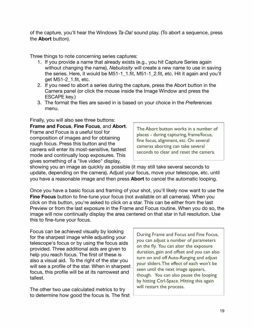
The Abort button works in a number of places - during capturing, frame/focus, fine focus, alignment, etc. On several cameras aborting can take several seconds to clear and reset the camera.
During Frame and Focus and Fine Focus, you can adjust a number of parameters on the fly. You can alter the exposure duration, gain and offset and you can also turn on and off Auto-Ranging and adjust your sliders. The effect of each won't be seen until the next image appears, though. You can also pause the looping by hitting Ctrl-Space. Hitting this again will restart the process.
19
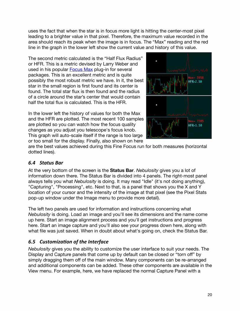
uses the fact that when the star is in focus more light is hitting the center-most pixel leading to a brighter value in that pixel. Therefore, the maximum value recorded in the area should reach its peak when the image is in focus. The “Max” reading and the red line in the graph in the lower left show the current value and history of this value.
The second metric calculated is the “Half Flux Radius” or HFR. This is a metric devised by Larry Weber and used in his popular Focus Max plug-in for several packages. This is an excellent metric and is quite possibly the most robust metric we have. In it, the best star in the small region is first found and its center is found. The total star flux is then found and the radius of a circle around the star’s center that would contain half the total flux is calculated. This is the HFR. In the lower left the history of values for both the Max and the HFR are plotted. The most recent 100 samples are plotted so you can watch how the focus quality changes as you adjust you telescope's focus knob. This graph will auto-scale itself if the range is too large or too small for the display. Finally, also shown on here are the best values achieved during this Fine Focus run for both measures (horizontal dotted lines).
6.4 Status BarAt the very bottom of the screen is the Status Bar. Nebulosity gives you a lot of information down there. The Status Bar is divided into 4 panels. The right-most panel always tells you what Nebulosity is doing. It may read "Idle" (it's not doing anything), "Capturing", "Processing", etc. Next to that, is a panel that shows you the X and Y location of your cursor and the intensity of the image at that pixel (see the Pixel Stats pop-up window under the Image menu to provide more detail).
The left two panels are used for information and instructions concerning what Nebulosity is doing. Load an image and you'll see its dimensions and the name come up here. Start an image alignment process and you'll get instructions and progress here. Start an image capture and you'll also see your progress down here, along with what file was just saved. When in doubt about what's going on, check the Status Bar.
6.5 CustomizaAon of the InterfaceNebulosity gives you the ability to customize the user interface to suit your needs. The Display and Capture panels that come up by default can be closed or “torn off” by simply dragging them off of the main window. Many components can be re-arranged and additional components can be added. These other components are available in the View menu. For example, here, we have replaced the normal Capture Panel with a
20

more compact version, the Mini Capture Panel. We’ve also put the Notes tool above the main image area and have a specialized control for the QSI cameras there as well. Not everything needs to be “docked” to the main Nebulosity window. For example, the dialog that controls the link to PHD Guiding is seen here floating above the main Nebulosity window.
6.5.1 Notes and HistoryEver wish you could jot down some information about the series you’re capturing? Something like “scope dewed up somewhere in the middle of the red frames” or “forgot the right spacer for the reducer on these” or even just to record the more mundane settings about the night’s progress? The Notes tool gives you handy place to do this. Your text is saved as plain text so any program can read it.
Also, ever wish you could remember just what settings you used as you processed an image for some step 12 steps ago? Open the History tool from the View menu and you’ll see a running log of exactly what you did.
6.5.2 Camera-‐specific DialogsThe main interface of Nebulosity lets you control the basic features of all cameras with the same interface, but some cameras have more features. For example, you may have a filter wheel attached to the camera (also controllable via scripts) or the camera may let you control the shutter (to make it easier to take dark frames). You’ll find camera-specific control dialogs here in the View menu as well.
21

6.5.3 External Filter WheelIf you’ve got an ASCOM-compliant filter wheel (Windows) or a Starlight Xpress filter wheel (Mac OS X), Nebulosity can connect to it and control it in the same way it controls filter wheels built into QSI, SBIG, or QHY cameras (see above). This control will let you select the desired filter. Keep in mind, you can also script your captures, telling Nebulosity to change filters as needed.
6.5.4 Pixel StatsThe Pixel Stats window will let you see the image intensity under the mouse pointer (like you also see in the Status Bar), but it will also show you a lot more. For color images, it splits this into the separate the R, G, and B values. For all images, it also shows local statistics and statistics on the whole image. Mouse over a star and it’ll tell you the HFR value for that star.
6.5.5 Link to PHD GuidingPHD Guiding is the popular freeware guiding package by Stark Labs. With it, guiding can be as simple as “Push Here Dummy.” With the PHD Guiding dialog, you can establish a link to PHD Guiding so that the two packages can talk to each other. This gives you two powerful features. First, it lets you pause guiding during the download of your main image. Some cameras are sensitive to interruptions on the USB bus and if the guide camera shares the USB bus, the image quality can be degraded. The “Pause during download” option will let you enable this feature.
The second feature is to enable “dithering” of the image’s location across frames. Between frames, Nebulosity can send a signal to PHD to tell it to move the “lock position” (the position of the crosshairs in PHD) by a small, random amount. Once PHD has moved the star and re-established stable guiding in the new location, a signal is sent to Nebulosity to let it know it can continue with the next frame in the series.
To do this, you must:1. Have PHD 1.8.6 or later running and tell it to “Enable Server” in the Tools menu
(PHD will remember if you last left the server on and restart it the next time you start PHD). If Windows asks you whether it’s OK to do this, tell it yes.
2. In Nebulosity’s PHD Guiding dialog, click on the “Connect” button (Note: Shift-click on the connect button and you can use a different TCP/IP port).
3. In the dialog, tell it how much “dither” to send. The dither sent will be a random number of pixels in X and Y, scaled by the level you pull down here. In the lowest level, the random numbers will vary from -0.5 to 0.5 pixels and in the highest they will vary from -1.5 to 1.5 pixels in the guide frame. Since people typically guide at shorter focal lengths than they image at, this will usually have a much larger effect in your main images.
4. It may be worth changing the “Settle threshold”. This specifies how far off the star can be from the lock position before PHD sends the message that it has gotten the star back on target and it is OK to resume your series capture.
22
6.5.6 Macro ToolIf you’ve ever wanted to replay the processing you did on one image and apply it to another image, the Macro Tool is for you. This kind of thing is very handy for processing mosaics and can be useful if you want to re-create a state of an image (so long as you have the output of the History tool). To use the Macro Tool, simply copy and paste items from the History dialog into the Macro Tool window (or select them - a triple-click works well here - and hit the History Tool’s “Append to Macro” button). When you’ve got the steps you want in the order you want, hit Run and Nebulosity will process the image accordingly.
You can, if you like, create the Macro Tool entries from scratch. Use previous entries in the History tool to see what the commands are supposed to look like.
23

7 Capturing ImagesMost of what you need to know to capture images was covered in the previous section on the Exposure section of the Capture Panel. There are a few topics worth considering on their own, however.
1. Monochrome vs. Color?2. One-shot color: RAW vs. RGB?3. File formats4. Camera Gain and Offsets
7.1 Monochrome vs. Color CamerasMonochrome cameras have CCD pixels that have no filter placed in front of them. Light simply hits the CCD array and the intensity gets recorded and saved. The CCD and Nebulosity don't care in the slightest whether you have no filter in place, an IR filter in place, a red filter, an Ha filter, or any combination thereof. To the camera and to Nebulosity, it's all black and white data that comes straight off of the CCD as every pixel operates just as every other pixel.
One-shot color cameras are a different story altogether. One-shot color cameras have tiny color filters placed over each CCD pixel. Typically, red, green, and blue filters are used (although other options for filter sets exist). For example, if one looked at a small 4x4 pixel patch of the CCD, one might see the arrangement shown on the right. Each pixel on the chip codes for only one color. So, if you have 1 million pixels, you have 500,000 green, 250,000 red and 250,000 blue pixels (CCD makers over-emphasize the green since our eyes are most sensitive to green). This is why you may hear people say that one-shot color imagers have less resolution than monochrome imagers.
To some degree, this is true. Yet, when you look at a digital photograph from a digital camera, you don't see this array of colors and you don't see a low-resolution shot. Digital cameras use this same kind of one-shot color CCD but produce crisp, full-color images with as many pixels in the output (each pixel having values for red, green, and blue) as they have pixels on the chip.
Whether the way this works is black magic or math is up for you to judge, but there are very good techniques for turning images from this "Bayer" matrix into a full-resolution, full-color image. This conversion is called "De-Bayering" or "De-Mosaicing" the raw CCD image. Depending upon the sophistication of the technique, the end result can be as poor as having resolution of one fourth the pixel count or as good as having nearly as good resolution as the full pixel count. In general, the "luminance" or "brightness" resolution is almost as good as a monochrome CCD, while the color resolution (the ability to rapidly change between red, green, and blue) is not as good, with techniques differing in just how much is lost. Fortunately, while intensity in both daylight and astronomical images can change very suddenly in an image (as we go from a black
24
background to a star), the hue (or color) changes much more gradually. Thus, we can "get away" with having less color resolution than we have intensity resolution.
It is for this very reason that even when using monochrome CCDs, imagers often shoot a luminance channel at full resolution and color channels at lower resolutions (by "binning" their CCDs to increase the signal to noise ratio but decrease the resolution). Thus, low color resolution but high intensity resolution is often chosen by monochrome CCD imagers, narrowing the potential difference between the quality of the output between the two CCD types.
7.2 One-‐shot color cameras: Should I capture RAW or RGB?Nebulosity lets you capture and save images from one-shot color cameras either in the RAW format from the CCD (where pixels still follow the Bayer pattern or whatever pattern is on your CCD) or in full-color RGB format. Here, by “RAW”, we don’t mean CR2, NEF, CRW or any other of the formats used in DSLRs. By “RAW”, we simply mean the pure, raw, unprocessed, unadulterated image data from the sensor of a one-shot color camera. All DSLRs are one-shot color cameras and all use the Bayer matrix described above. The data from this matrix, as noted above, is monochrome (grayscale) data. Before converting this into color, it is “RAW”. (This RAW data could hypothetically be stored in CR2, NEF, etc. format or it could be stored in FITS, PNG, TIFF, or any other format - it’s still the same data from the sensor.)
You have a choice in Nebulosity whether to keep the data in this pure RAW format on capture or whether you want to convert it to color. Many people instinctively want to convert it to color (since their camera is a color camera). This is an option and if you select this in your Preferences (Capture, Acquisition mode), Nebulosity first captures this raw data from the CCD and then applies a de-mosaic function to convert it into a full-color image. This full-color image is then saved and the raw data are lost.
On-the-fly conversion to RGB is perhaps the simplest and most intuitive format for the user. You ask for a full-color image and you get it. Many fine images are created this way, but it does have a few drawbacks. First, each image is 3x as large as a RAW image, taking up 3x as much space on your hard disk. Second, on-the-fly de-mosaic takes some amount of time for each image. Thus, if your capture machine is a lower-end machine, you may want to capture in RAW and convert to RGB later.
Finally, RAW capture has one more advantage. Dark frame, bias frame, and light frame pre-processing is somewhat more accurate at fixing images in RAW mode than in RGB mode. In addition, if you capture in RAW format you can use the powerful Bad Pixel Map tool, which must be used prior to the de-mosaic process (see 5.3 Bad Pixel Mapping). For these reasons, it is better to capture your one-shot color data in RAW format and convert it later.
If you do choose to save the data in RAW format and not convert on the fly, you will pre-process your images in B&W / RAW mode and de-mosaic all of the pre-processed
25

images prior to stacking (otherwise, you'll put red pixels atop green pixels, etc. and lose all hope of making a final color image).
7.3 File formatsNebulosity can read just about any valid FITS image file out there (it makes extensive use of NASA's FITS library) and can write images in a range of useful FITS formats. The format it will write in is set by your choices in the Preferences menu. This is true not only for captures but for any time you pull down "Save" from the File menu (thus letting Nebulosity act as a FITS format converter).
For color images, you have several options. RGB FITS is the default. Here, a single file holds the red, green, and blue data after the image has been converted into a full-color image (de-mosaic). Unfortunately, there are two ways in which other programs have chosen to implement RGB data in FITS files. The differences are esoteric to most (and concern using 3 HDU's vs. using 3 axes) until one realizes that programs using one standard don't generally like files written by the other standard. So, Nebulosity will not only read both formats just fine, but it'll write either of them. They're labeled RGB FITS: ImagesPlus and RGB FITS: Maxim / AstroArt.
In addition to this, Nebulosity will write three separate FITS files for a full-color image if you so desire. One will have the red data, one the green, and one the blue. This is a far more cumbersome way of dealing with the data and unless you have a very good reason to do this, odds are you shouldn’t do this. Nebulosity can save in a compressed FITS format to save space. The compression algorithm used is native to FITS and is a lossless one. You're doing no harm to your data by using it. If you don't wish to use compression (e.g., you wish to use a program that doesn't support it), simply uncheck this in the Preferences menu. (Note: Maxim DL uses a "compressed FITS" format that is proprietary and not the standard FITS compression. Nothing outside of Maxim DL can read this format and Maxim doesn't seem to always like FITS' native compressed format.)
If space is not a concern and you want to absolutely maximize the quality of the saved data, you can choose to save the data in 32-bit floating point format. This is the native format used internally. Data files will be twice as large and, in truth, will likely show little more than the default of saving in 16-bit integers.
Finally, you can choose to rescale your data to 15-bits rather than the full 16-bits possible. Thus, your data will be scaled into the range of 0-32767 rather than 0-65535. This is an option to support several programs.
Right click on a .fit file in Windows and select "Open With" and "Choose Program". Browse to Nebulosity (c:\Program Files (x86)\Nebulosity3\Nebulosity3.exe) and select "Always use the selected program". Or, on a Mac, right-click on it and pull down Get Info. Under Open With, select Nebulosity and then click the Change All button. Now, double-clicking on .fit file will automatically start Nebulosity and load the image.
26
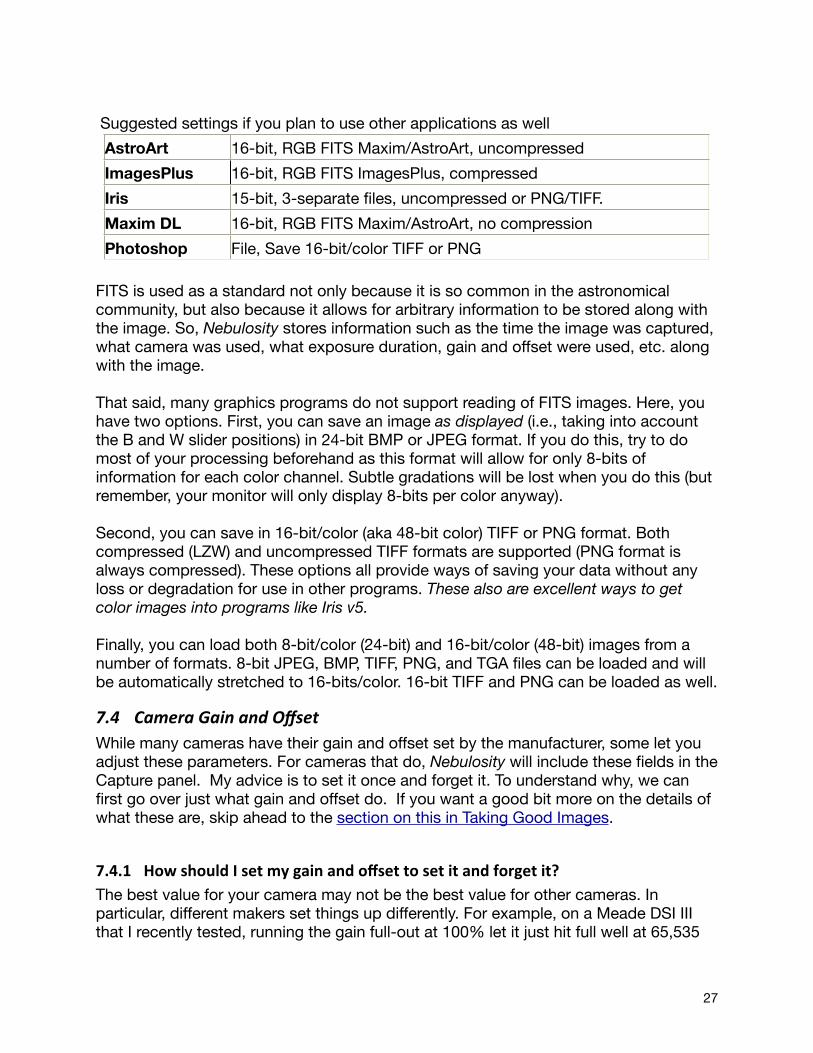
Suggested settings if you plan to use other applications as well
AstroArt 16-bit, RGB FITS Maxim/AstroArt, uncompressed
ImagesPlus 16-bit, RGB FITS ImagesPlus, compressed
Iris 15-bit, 3-separate files, uncompressed or PNG/TIFF.
Maxim DL 16-bit, RGB FITS Maxim/AstroArt, no compression
Photoshop File, Save 16-bit/color TIFF or PNG
FITS is used as a standard not only because it is so common in the astronomical community, but also because it allows for arbitrary information to be stored along with the image. So, Nebulosity stores information such as the time the image was captured, what camera was used, what exposure duration, gain and offset were used, etc. along with the image.
That said, many graphics programs do not support reading of FITS images. Here, you have two options. First, you can save an image as displayed (i.e., taking into account the B and W slider positions) in 24-bit BMP or JPEG format. If you do this, try to do most of your processing beforehand as this format will allow for only 8-bits of information for each color channel. Subtle gradations will be lost when you do this (but remember, your monitor will only display 8-bits per color anyway).
Second, you can save in 16-bit/color (aka 48-bit color) TIFF or PNG format. Both compressed (LZW) and uncompressed TIFF formats are supported (PNG format is always compressed). These options all provide ways of saving your data without any loss or degradation for use in other programs. These also are excellent ways to get color images into programs like Iris v5.
Finally, you can load both 8-bit/color (24-bit) and 16-bit/color (48-bit) images from a number of formats. 8-bit JPEG, BMP, TIFF, PNG, and TGA files can be loaded and will be automatically stretched to 16-bits/color. 16-bit TIFF and PNG can be loaded as well.
7.4 Camera Gain and OffsetWhile many cameras have their gain and offset set by the manufacturer, some let you adjust these parameters. For cameras that do, Nebulosity will include these fields in the Capture panel. My advice is to set it once and forget it. To understand why, we can first go over just what gain and offset do. If you want a good bit more on the details of what these are, skip ahead to the section on this in Taking Good Images.
7.4.1 How should I set my gain and offset to set it and forget it? The best value for your camera may not be the best value for other cameras. In particular, different makers set things up differently. For example, on a Meade DSI III that I recently tested, running the gain full-out at 100% let it just hit full well at 65,535
27
ADU. Running below 100% and it hit full-well at 40,000 or 30,000, or 10,000 ADU. There's no point in running this camera at anything less than 100% gain. On a CCD Labs Q8-HR I have, even at gains of 0 and 1 (on its 0-63 scale), the camera would hit 65535 on bright objects (like the ceiling above my desk). There's no point in running this camera at gains higher than 0 or 1.
Why is there no point? The camera only holds 25k e-. If a gain of 0 or 1 gets me to 0.38 e-/ADU (so that those 25k e- become 65535), running at 0.1 e-/ADU will only serve to limit my dynamic range. Each single electron already comes out to more than 2 ADU.
So, to determine the gain and offset to use:1) Take a bias frame and look for the minimum value in it. Is it at least, say 100 and less than a thousand or a few thousand? If so, your offset is fine. If it's too low, boost the offset. If it's high, drop it. Repeat until you have a bias frame with an offset in, roughly 100 - 1000. Don't worry about precision here as it won't matter at all in the end. You now know your offset. Set it and forget it. Never change it.
2) Aim the camera at something bright or just put it on your desk with no lens or lenscap on and take a picture. Look at the max value in the image. Is it well below 65k? If so, boost the gain. Is it at 65k? If so drop the gain. Now, if you're on a real target (daylight ones are great for this) you can look at the histogram and see the bunching up at the top end as the camera is hitting full-well. Having that bunch-up roughly at 65,535 plus or minus a bit is where you want to be. If you pull up just shy, you'll get the "most out of your chip" but you'll also have non-linearity up there. You've got more of a chance of having odd color casts on saturated areas, for example, as a result. If you let that just clip off, you've lost a touch but what you've lost is very non-linear data anyway (all this assumes, BTW, an ABG chip which all of these cams in question are). Record that gain and set it and forget it. Never change it.
By doing this simple, daytime, two-step process you've set things up perfectly. You'll be sure to never hit the evil of zero and you'll be making your chip's dynamic range fit best into the 16-bits of your ADC. Again, all the cameras in question have full-well capacities below 65,535 so you are sure to have enough ADUs to fit every electron you record into its own intensity value.
28
8 Overview of Image ProcessingYou've taken your images and are now comfortably inside. Now what? How do you get all those raw frames to look like a nice pretty stack? Just what the heck is Bad Pixel Mapping? Should I try Drizzle?
The rest of the manual provides answers to many individual questions and documents each of the tools in more detail. The goal of this section is to let you see how all of these fit together and to give you the necessary information to choose a path through the initial processing of your data. This alone won't give you a full understanding of how each tool works (see the individual section for each tool), but it should help put all the pieces together. In addition to the coverage here, there are several tutorials and walk-throughs available on the web.
The basic steps are as follows: 1. Decide on how you’ll deal with hot pixels (BPM vs. Dark subtraction)2. Prepare and any sets of darks, flats or bias frames to remove hot pixels,
vignetting, etc.3. Convert RAW images into color via Demosaic (if one-shot CCD used and
captured in RAW, which you really should do) and square-up your pixels (if needed)
4. (optional) Normalize the images5. (optional) Grading and Removing Frames6. Stack the images (Align and Combine)7. Crop the image to clean it up8. (color only) Remove skyglow hue9. Stretch the image (Levels, DDP, etc)
8.1.1 Deciding on Bad Pixel Mapping vs. Dark Subtrac5onBoth of these techniques are designed to deal with the thermal noise inherent in your images and the resulting "hot pixels" that show up in the same spot on the image in each frame. Dark subtraction is the traditional way of doing this. It works by simply subtracting the value for each pixel in your "master dark" from the value of that pixel in each light frame. If your light frames and dark frames were taken with the same exposure duration and at the same temperature, dark subtraction will remove the hot pixels (and "luke-warm" pixels as well - any thermal noise, not just the brightest). This can work very well if you control the temperature, exposure duration, and take a lot of dark frames. If you don't do these, you can end up with "holes" in the image (black spots where the hot pixel used to be), incomplete hot pixel removal, and you can inject noise into your light frames (see above).
Bad Pixel Mapping works differently. You first create a "Bad Pixel Map" (Batch, Bad Pixels, Make Bad Pixel Map) using a dark frame or stack of dark frames. A slider appears to let you set a threshold (feel free to use the default). Values in the dark frame that are above the threshold say "this pixel is bad". Bad pixels, and only bad pixels are fixed in your light frames by using surrounding good pixels to help fill in what this pixel
29

should have been. For many cameras (in my experience, the cooled cameras with Sony sensors work wonderfully), this is an exceptionally powerful technique as the hot pixels are removed effectively with no noise being injected. It's also very flexible as you can use the same "master dark" from night to night and from exposure duration to exposure duration just by adjusting the slider and making new maps as needed.
Note: If you use Bad Pixel Mapping you will not use Dark Subtraction and vice versa. One or the other but no need for both. If you use Bad Pixel Mapping you can still use flats and bias frames and it doesn't matter whether you apply BPM before or after your other pre-processing. BPM just locally fixes the bad pixels and doesn’t touch any non-bad pixels. In fact, using both flats and bias frames is a good thing.
If you’re using Dark Subtraction, keep in mind that your dark frames already have the bias current in them. You will not typically use both darks and biases as a result. If you do, you’ll end up removing the bias twice (which injects the inverse of the bias back in). So, don’t do that.
When using flats, it can be a good idea to let Nebulosity smooth the flats a bit for you. At the very least, if using a one-shot color camera, use the 2x2 mean or CFA scaling option in the pre-process tool. I often use a 7 pixel blur. This reduces the noise in the flats and makes for smoother images.
8.1.2 Applying the darks, flats, and biasesOdds are you’ve taken some number of darks, flats, and/or bias frames (control frames) in addition to your lights. What the heck do you do with them? Your goal is to combine these control frames as needed (to reduce the noise in them) and use them to fix the problems in your lights. Your lights will have not only the signal from your DSO in them, but they will have dark current and bias current and will probably not be perfectly evenly illuminated. Pre-processing is the step that applies these control frames to your lights.
Before we apply them, though, we typically want to stack (or combine) multiple control frames. Having more than one dark, flat, and/or bias frame is a good thing as each individual frame has both the artifact you want to remove from your lights and random noise. Stack a bunch of these together and the random noise goes away leaving you with a clean image of the artifact you want to remove. Use just one and you remove the artifact and whatever random noise that one frame had. Since it's random noise won't be the same as the random noise in your image, using just one dark, flat, or bias will actually inject noise into your light frame and make it noisier. This is why people take a good number (20-100) of each of these.
In Nebulosity, you can stack them all first (to make “master” control frames), or you can stack these on the fly while correcting your lights. This all happens in the Pre-process
30
image sets tool.
This tool allows you to pre-process 1-5 sets of lights using 0-3 sets of darks, 0-2 sets of bias frames, and 0-5 sets of flats. If you pass in more than one control frame (flat, dark, or bias), it will stack it on the fly for you. If you want to apply a bias frame or a dark frame to your flats, it can do that too. Got data from a mono camera with 5 filters each with its own flat and with a few different exposure durations (and therefore a few different darks)? No problem.Using the tool is covered in more detail in the Multiple-Set Pre-Processing section, but can be quickly summarized as follows:
1. Pull down Batch, Pre-process image sets2. Click on the buttons to define your “control sets”. For example, click on “Dark
1” to select one or more dark frames that you can now refer to as “Dark 1”.3. (optional) If you want to do things to your flats on the fly, tell it which bias and
dark to apply (both are entirely optional) and whether you want to blur the flats at all. If you’re using a one-shot color camera, you will at least want to use the 2x2 mean here to remove the Bayer matrix. Blurring the flats will help reduce the noise (grain) in them.
4. Click on the buttons to define your sets of light frames (“Light 1” through “Light 5”). You can have 1-5 sets of lights that you work on at once.
5. Select which biases, darks, and flats get applied to each of the sets of lights.6. If this all made no sense, see the Multiple-Set Pre-Processing section where it is
laid out in more detail.
8.1.3 Using Bad Pixel MappingLet’s say you chose not to use traditional dark subtraction to take care of those hot pixels and instead want to use bad pixel mapping. You still will probably apply flats and/or biases (bias frames are good to use if you’re using BPM). To apply BPM to your light frames:
1. Create a Bad Pixel Map if you don't already have one. Batch, Make Bad Pixel Map. Select a dark frame or stack and start off by just hitting OK to use the default threshold. If for some reason you don’t like that threshold, adjust the slider to let you remove more or fewer pixels.
2. During pre-processing, click one of the Dark buttons and load the Bad Pixel Map you created in step 1.
3. For that entry, go to where it says “Dark Subtract” and pull down one of the BPM options. If you’re using a mono camera, use “BPM Mono”. If it’s a one-shot color camera but you’ve not demosaic’ed yet, use “BPM Color”. If you’ve converted to color already, go back and read why I suggest you use RAW and don’t convert to color yet.
Prior versions of Nebulosity had a separate tool to pre-process a single set of lights with pre-stacked bias / dark / flat frames. This has been removed as the Pre-process image sets tool can do anything the old one could do and more. This tool is the same as the Multi-set pre-process tool found in 2.3 and later.
31
8.1.4 Conver5ng RAW images to Color and/or Pixel Squaring (aka Reconstruc5on)The last step before stacking your images is to convert them to color (if they are from a one-shot color camera and you captured in RAW) and square them up as needed. Some cameras have pixels that are not square and this will lead to oval rather than round stars. The process of demosaic'ing (color reconstruction) and/or pixel squaring is called Reconstruction in Nebulosity and the details of this can be found in the section on Reconstruction: Demosaic’ing and Pixel Squaring.
Note, you can tell if your images need to be squared up by pulling down Image, Image Info. Near the bottom you will see the pixel size and either a (0) or (1). If it is (1), the pixels are square. Of course, the pixel dimensions will be the same in this case too.
To reconstruct all of your light frames, simply: 1. Pull down Batch, Batch Demosaic + Square (if images are from a one-shot color
camera) or Batch Square (if images are from a monochrome camera or you just feel like squaring up a color cam's but keeping the image as monochrome for some reason).
2. Select your frames 3. Ideally, Nebulosity will start loading and reconstructing the frames. If it pops up
a dialog asking for things like offsets, it means it did not recognize what camera captured the image (or you have “manually override color reconstruction” checked in the Preferences). If this happens, consult the Reconstruction: Demosaic’ing and Pixel Squaring section.
4. In the end, you'll have a set of images named "recon_OriginalImage.fit"
8.1.5 Normalize Images (op5onal)All things being equal, your 50 frames of M101 should all have the same intensity. They were taken on the same night one right after the other and all had the same exposure duration. So, they should be equally bright, right? Yes, but there's that nagging "all things being equal" we supposed and, well, all things aren't always equal. For example if you start with M101 high in the sky and image for a few hours it starts picking up more skyglow as the session goes on, brightening the image up. That thin cloud that passed over did a number on a frame that still looks good and sharp, but isn't the same overall intensity as the others, etc. All things are not always equal.
If you're doing the Average/Default method of stacking, you need not worry about this issue unless the changes are really quite severe. If you're using standard-deviation based stacking, Drizzle, or Colors in Motion, it is a good idea to normalize your images before stacking. What this will do is to get all of the frames to have roughly the same brightness by removing differences in the background brightness and scaling across frames.
There are two methods you can use to normalize images. The first (and original), performs a purely linear stretch to put the black and white points in roughly the same place. To normalize a set of images, simply:
32
1. Pull down Batch, Normalize images 2. Select the light frames you want to normalize 3. In the end, you'll have a set of images named "norm_OriginalName.fit"
The second, more advanced tool, attempts to equate the histograms of two or more images. This is a more complex stretching procedure that can account for more kinds of changes across images. To use this Match Histogram tool, simply:
1. Pull down Batch, Match Histograms2. Select a reference frame and press OK. This will serve as the template image
that others will be matched to.3. Select the set of frames you wish to normalize4. In the end, you'll have a set of images named "histm_OriginalName.fit"
8.1.6 Grading and Removing Frames (op5onal)Sometimes bad things happen. The tracking goes awry, a breeze blows, you trip over the mount, etc. This is a good time to find those "bad" frames and pretend they never happened. There are two tools to help you here, covered briefly here and in more depth in Previewing and Grading Images.
8.1.6.1 Grade Image QualityThis will look at a set of frames and attempt to automatically grade them as to how sharp they are relative to each other. The idea here being that you'll not use the least sharp frames. Pull down Batch, Grade Image Quality and point it to your light frames. It will rename them (or copy them with a new name) denoting how sharp each frame is.
8.1.6.2 Image PreviewThis will let you easily go through your images one by one to examine them, (optionally) rename them, and/or (optionally) delete them. File, Preview Files. If you've not tried this, try it. It's quick, easy, and immensely useful.
8.1.7 Stacking: Align and CombineIt's now time to Align and Combine (stack) your light frames. Here, there are a large number of options as to how to proceed. We'll start with the basic version first and then detail the other paths you can take.
1. Pull down Batch, Align and Combine Images 2. If you're not on an alt-az mount, hit OK, keeping the defaults of saving the stack,
using Translation, and Average / Default stacking. If you're on an alt-az mount, you'll need to include rotation, so change the Alignment Method to Translation + Rotation.
3. Select your light frames 4. Find a star in your image that's not ultra faint and not big and bloated. Move
your mouse over it to make sure that the core of the star isn't all 65535 (the max possible value). Click on that star and Nebulosity will advance to the next image. If your mount's tracking is at all decent, the same star on the next frame should be circled. If the circle is on the right star (don't worry about centering), just hit
33
Ctrl-click (or Command-Click on the Mac) to tell Nebuolsity "yes, that's the right star and I want to use this frame". If it missed the star, just click on it (don't worry about being precise). If the frame is a bad one and you'd like to skip it and not include it, hit Shift-click.
5. If you're doing Translation + Rotation (or Drizzle), you'll need to find a second star and run through each frame again. Try to pick one that's not very close to the first star.
6. When you're done (the Status Bar will show you your progress), Nebuolsity will align and combine all the images and pop up a dialog asking you for a filename to save the resulting stack in.
There you have it! Basic stacking. There are some more advanced options you can try: 1. Translation + Rotation (+ Scale): The normal Translation alignment will only shift
images by whole pixels and does not account for any rotation across frames. Running these will shift the images by fractional pixels (interpolating them as needed), rotate them as needed and, if selected, scale them as needed to co-register the images.
2. Drizzle: Drizzle is a powerful technique that will align, combine, and increase the resolution of your images during stacking. It is suitable for alt-az mounts as rotation is included in the alignment. You will therefore need to select two stars during alignment. Make sure you have Normalized your images at some point first.
3. Colors in Motion: This tool is only available for images from one-shot color cameras that have not been converted into color yet. It will align the images and convert them into color at the same time. It is a translation-only based alignment.
4. Standard Deviation (SD) stacking: Instead of taking the average value for each pixel (across images), take the average but toss out "outliers" or values that are atypical. Thus, if a hot pixel "crosses over" a pixel in the aligned image (the hot pixel didn't move but the frame did when the stars were aligned), this bright hot pixel will be an atypical sample and will be tossed out before averaging. To use this technique, you must first do your alignment, saving each frame first and then pass these aligned frames ("align_OriginalName.fit") into Align and Combine again, selecting "None (fixed)" as the alignemnt method (and one of the Std. Dev. thresholds in the Stacking Function). Make sure you have Normalized your images at some point.
8.1.8 Crop off the edgesAfter stacking, odds are you've got a dark border around your image as Nebulosity tried to make an output image big enough to hold everything from every frame (an exception here is in rotation where you will have bits cut off at times). Odds are you don't want this bit and it'll just make the histograms look funky when you're stretching. Use the mouse to define a rectangle that has the good part of the image and pull down Image, Crop. Save this with a new name.
If you don’t select a region to crop and pull down Image, Crop a dialog will appear asking you exactly how many pixels you want to remove from each side.
34
8.1.9 Remove the Skyglow ColorIf you're shooting in color (one shot or having combined frames), odds are the background sky is not a nice neutral gray, but rather something rather unpleasant (green, pink, and orange are common). This comes from the color of your skyglow. Fortunately, it's easy to remove. Simply pull down Image, Adjust Color Offset (unless you've got a reason, accept the default values) or pull down Image, Auto Color Balance. Save this with a new name.
8.1.10 StretchingNow, the fun begins as it's time to see what you really have in that shot. Sitting atop that skyglow should be the faint galaxy or nebula you were shooting and stretching is how we bring this out. There are three main tools for stretching in Nebulosity. The first is the Levels / Power Stretch, the second is Digital Development Processing (DDP), and the third is Curves. For each of these, more detail is provide in the section on Image Adjustment.
The goal in each of these is to pull your image's intensity profile (histogram) and stretch it so that very low contrast differences are made more apparent. Thus, you are pulling your faint galaxy arms away from the skyglow and doing things like sending the skyglow down to a nice dark background. When doing this:
• Keep your eye on the histogram. The histogram is your friend. • Until the very last steps of stretching, don't let the left edge of the histogram get
cut off and don't bang too much (e.g. the core of your galaxy) into the right edge of the histogram. Once they hit the edges (0 and 65535), you'll never resolve details in there again.
• Turn off auto-scaling (or let Nebulosity do this for you) so that what you're seeing on the screen is the full 16-bit data in all its glory. This will help you use the full range of intensities your image can take. Remember, the B and W sliders are just there to make the image prettier on the screen (they do a stretch for display but don't really affect the underlying image). So, have them at full left and full right and then start to stretch. (If you're in auto-scale when you enter Levels, it will turn it off and set these at the extremes for you).
• Don't try to do everything in one pass. Make several passes over the image to slowly pull it into the condition you want it.
• Save often
8.1.10.1 Levels / Power StretchThe Levels tool in Nebuolsity does the same math to your image as tools like PhotoShop's Levels tool. You're setting a black point (top sider), a white point (middle slider) and a midpoint or "power" (bottom slider). This is much like a “Curves” tool but with a fixed basic shape to the curve (see Levels / Power Stretch). With several passes over the data you can build up a complex “Curves” transformation to your data. In general, for the first few passes, have the "power" slider be less than one (try values like 0.6) as this will help accentuate the low-contrast details and pull them out. Start getting the details to pull apart from the background before you work too hard on
35

pushing the background to being dark. You can always darken the background later.
8.1.10.2 Digital Development ProcessingDDP is a tool that applies a special transformation designed to make linear CCDs behave more like film. If you use DDP, do it first or without using the Levels tool much beforehand as the math behind it expects you to have not altered the linear response of your CCD's image. I find that DDP works best if the skyglow is not too bright to begin with. Feel free to use the Levels tool and adjust the black-point (first) slider to bring the histogram nearer to the left edge before running DDP. Just don't start adjusting the Power (aka midpoint, aka 3rd slider) in the Levels tool before using DDP.
8.1.10.3 CurvesThe Curves tool gives you a lot more flexibility than you would get with either DDP or Levels and can be used both for initial stretching and for fine-tuning the results of something like DDP. Feel free to use all of the tools and to mix the tools as you see fit.
To use the Curves tool, simply grab one of the two blue dots and move it around. These two “control points” help you draw out the curve which is always shown in the dialog. By having these two points and the two endpoints, you can draw a wide range of very useful curves without getting into trouble by making a very odd transformation of your image. As with Levels, you can do a lot more in several iterations than you can in just one. As you re-use the tool, you’re effectively building up a more and more complex curve.
36

9 Image Pre-‐Processing: The Details
1. Pre-processing: Theory2. Pre-processing one or more sets using the Multiple Set tool3. Automatic dark frame scaling4. Bad Pixel Mapping
9.1 Pre-‐processing: TheoryOur CCD images have a number of artifacts in them. Typical artifacts include hot pixels (bright dots that appear in the same place on the image and that get worse with increased exposure duration or temperature), vignetting (un-even illumination of the field), dust spots (large blobs or donuts that appear superimposed on the image, looking a bit like a watermark), and noise (a static-like or grainy appearance to the image).
We can fix these by taking and applying a series of control frames that have the various defects but not our image and using them to remove the defects. When thinking about this, it is useful to consider the following:
LightImage = TargetImage × NonFlatness + DarkCurrent + BiasCurrentDarkImage = DarkCurrent + BiasCurrentBiasImage = BiasCurrentFlatImage = NonFlatness + BiasCurrent + DarkCurrent_flat
Our goal here then is to apply the following formula to our image:
NewImage = RawImage − DarkImage − BiasImageFlatImage − DarkImage_flat − BiasImage
Both Dark Frames and Bias Frames are taken with no light hitting the camera. Dark frames are to be taken under the same circumstances as your Light Frames (e.g., the RawImage pictures of your DSO). Use the same duration of exposure and try to have the CCD at the same temperature (e.g., if you use the TEC in your DSO shots, use it in the Dark frames. Often, these are taken in the same imaging session or a collection of "master" dark frames for various imaging situations is compiled. Always take a number of dark frames (somewhere between 10 and the number of exposures used in your light frames) and combine them (average or median) to create a suitable dark frame to be used during pre-processing.
Bias frames can be taken at any time simply by covering the telescope or putting a lenscap on the camera and taking a series of short exposures (e.g., 10 ms). Take a good number of these some day when you're bored and combine them (average or median) to create a master bias frame.
Note, the dark current in a flat image (DarkCurrent_flat) is typically far, far less than in your light frame or dark frames since the exposure durations are typically a lot less for your flats and can typically be ignored.
37
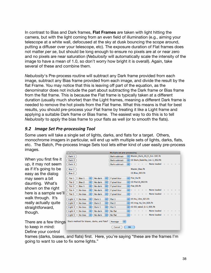
In contrast to Bias and Dark frames, Flat Frames are taken with light hitting the camera, but with the light coming from an even field of illumination (e.g., aiming your telescope at a white wall, defocused at the sky at dusk bouncing the scope around, putting a diffuser over your telescope, etc). The exposure duration of Flat frames does not matter per se, but should be long enough to ensure no pixels are at or near zero and no pixels are near saturation (Nebulosity will automatically scale the intensity of the image to have a mean of 1.0, so don't worry how bright it is overall). Again, take several of these and combine them.
Nebulosity's Pre-process routine will subtract any Dark frame provided from each image, subtract any Bias frame provided from each image, and divide the result by the flat Frame. You may notice that this is leaving off part of the equation, as the denominator does not include the part about subtracting the Dark frame or Bias frame from the flat frame. This is because the Flat frame is typically taken at a different duration (usually much shorter) than the Light frames, meaning a different Dark frame is needed to remove the hot pixels from the Flat frame. What this means is that for best results, you should pre-process your Flat frame by treating it like a Light frame and applying a suitable Dark frame or Bias frame. The easiest way to do this is to tell Nebulosity to apply the bias frame to your flats as well (or to smooth the flats).
9.2 Image Set Pre-‐processing ToolSome users will take a single set of lights, darks, and flats for a target. Others, monochrome imagers in particular, will end up with multiple sets of lights, darks, flats, etc. The Batch, Pre-process Image Sets tool lets either kind of user easily pre-process images.
When you first fire it up, it may not seem as if it’s going to be easy as the dialog may seem a bit daunting. What’s shown on the right here is a sample we’ll walk through. It’s really actually quite straightforward, though.
There are a few things to keep in mind:Define your control frames (darks, biases, and flats) first. Here, you’re saying “these are the frames I’m going to want to use to fix some lights.”
38
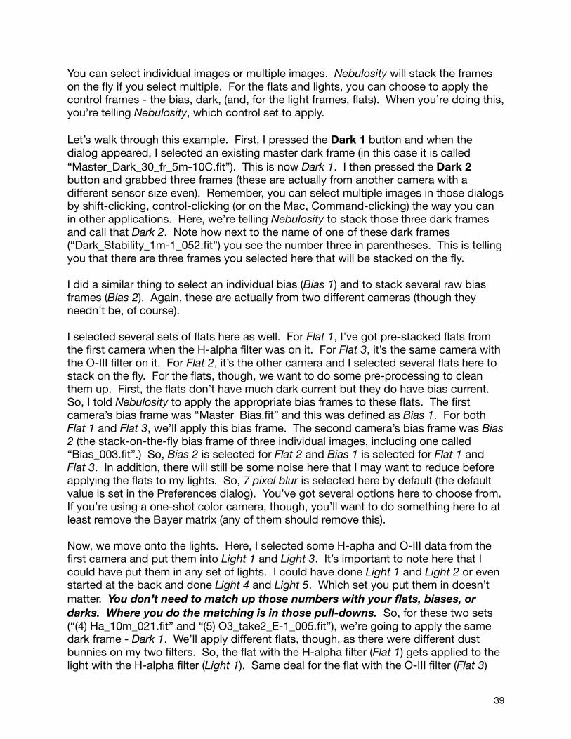
You can select individual images or multiple images. Nebulosity will stack the frames on the fly if you select multiple. For the flats and lights, you can choose to apply the control frames - the bias, dark, (and, for the light frames, flats). When you’re doing this, you’re telling Nebulosity, which control set to apply.
Let’s walk through this example. First, I pressed the Dark 1 button and when the dialog appeared, I selected an existing master dark frame (in this case it is called “Master_Dark_30_fr_5m-10C.fit”). This is now Dark 1. I then pressed the Dark 2 button and grabbed three frames (these are actually from another camera with a different sensor size even). Remember, you can select multiple images in those dialogs by shift-clicking, control-clicking (or on the Mac, Command-clicking) the way you can in other applications. Here, we’re telling Nebulosity to stack those three dark frames and call that Dark 2. Note how next to the name of one of these dark frames (“Dark_Stability_1m-1_052.fit”) you see the number three in parentheses. This is telling you that there are three frames you selected here that will be stacked on the fly.
I did a similar thing to select an individual bias (Bias 1) and to stack several raw bias frames (Bias 2). Again, these are actually from two different cameras (though they needn’t be, of course).
I selected several sets of flats here as well. For Flat 1, I’ve got pre-stacked flats from the first camera when the H-alpha filter was on it. For Flat 3, it’s the same camera with the O-III filter on it. For Flat 2, it’s the other camera and I selected several flats here to stack on the fly. For the flats, though, we want to do some pre-processing to clean them up. First, the flats don’t have much dark current but they do have bias current. So, I told Nebulosity to apply the appropriate bias frames to these flats. The first camera’s bias frame was “Master_Bias.fit” and this was defined as Bias 1. For both Flat 1 and Flat 3, we’ll apply this bias frame. The second camera’s bias frame was Bias 2 (the stack-on-the-fly bias frame of three individual images, including one called “Bias_003.fit”.) So, Bias 2 is selected for Flat 2 and Bias 1 is selected for Flat 1 and Flat 3. In addition, there will still be some noise here that I may want to reduce before applying the flats to my lights. So, 7 pixel blur is selected here by default (the default value is set in the Preferences dialog). You’ve got several options here to choose from. If you’re using a one-shot color camera, though, you’ll want to do something here to at least remove the Bayer matrix (any of them should remove this).
Now, we move onto the lights. Here, I selected some H-apha and O-III data from the first camera and put them into Light 1 and Light 3. It’s important to note here that I could have put them in any set of lights. I could have done Light 1 and Light 2 or even started at the back and done Light 4 and Light 5. Which set you put them in doesn’t matter. You don’t need to match up those numbers with your flats, biases, or darks. Where you do the matching is in those pull-downs. So, for these two sets (“(4) Ha_10m_021.fit” and “(5) O3_take2_E-1_005.fit”), we’re going to apply the same dark frame - Dark 1. We’ll apply different flats, though, as there were different dust bunnies on my two filters. So, the flat with the H-alpha filter (Flat 1) gets applied to the light with the H-alpha filter (Light 1). Same deal for the flat with the O-III filter (Flat 3)
39
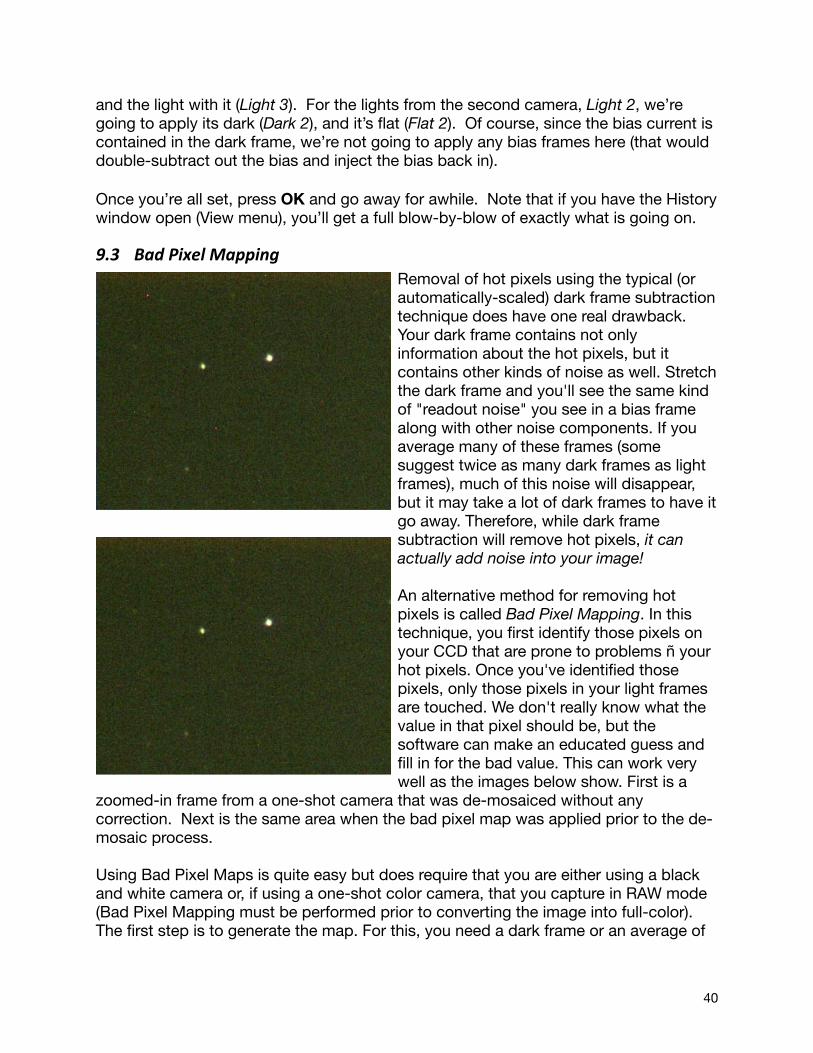
and the light with it (Light 3). For the lights from the second camera, Light 2, we’re going to apply its dark (Dark 2), and it’s flat (Flat 2). Of course, since the bias current is contained in the dark frame, we’re not going to apply any bias frames here (that would double-subtract out the bias and inject the bias back in).
Once you’re all set, press OK and go away for awhile. Note that if you have the History window open (View menu), you’ll get a full blow-by-blow of exactly what is going on.
9.3 Bad Pixel MappingRemoval of hot pixels using the typical (or automatically-scaled) dark frame subtraction technique does have one real drawback. Your dark frame contains not only information about the hot pixels, but it contains other kinds of noise as well. Stretch the dark frame and you'll see the same kind of "readout noise" you see in a bias frame along with other noise components. If you average many of these frames (some suggest twice as many dark frames as light frames), much of this noise will disappear, but it may take a lot of dark frames to have it go away. Therefore, while dark frame subtraction will remove hot pixels, it can actually add noise into your image!
An alternative method for removing hot pixels is called Bad Pixel Mapping. In this technique, you first identify those pixels on your CCD that are prone to problems ñ your hot pixels. Once you've identified those pixels, only those pixels in your light frames are touched. We don't really know what the value in that pixel should be, but the software can make an educated guess and fill in for the bad value. This can work very well as the images below show. First is a
zoomed-in frame from a one-shot camera that was de-mosaiced without any correction. Next is the same area when the bad pixel map was applied prior to the de-mosaic process.
Using Bad Pixel Maps is quite easy but does require that you are either using a black and white camera or, if using a one-shot color camera, that you capture in RAW mode (Bad Pixel Mapping must be performed prior to converting the image into full-color). The first step is to generate the map. For this, you need a dark frame or an average of
40

several dark frames. Ideally, this will be a combination of several frames taken at the longest exposure duration you expect to use. Pull down Make bad pixel map from the Batch menu and load the dark frame when prompted. A slider will now appear and the display will show you your hot pixels. Nebulosity attempts to come up with a reasonable position of the slider for you. Here, we have the default setting and display for creating the Bad Pixel Map using a sample dark frame.
At this point, you can adjust the slider and you'll see the number of bad pixels identified change (here, showing 821 bad pixels). What you’re seeing is actually the dark frame after some brightening and stretching. Currently flagged bad pixels are the black dots that are on the mostly gray background. The white dots shown here are hot pixels that haven’t been marked as bad in this example. Move the threshold slider to the left and more pixels get marked as bad and more black dots thus appear. Move it to the right and fewer black dots appear (more white dots should appear). What you are doing is moving a threshold - saying that anything above this intensity is a bad pixel (shows up as black) and anything below it is a good pixel. When you like your map, click on Done and you will be prompted for a name to give this Bad Pixel Map. Give it a meaningful name, as you may well want to create several maps. If you used a 5-minute dark frame, you could use that dark frame to make several maps - one for ~5-minute exposures, one for ~1-minute exposures, and one for ~20-second exposures for example by using different values of the threshold (letting fewer hot pixels show for the shorter exposure maps). There is no "exact right value" here. You're simply telling Nebulosity which pixels not to trust.
Once you have your map, you can now process your light frames. In the Pre-process image tool change the entry that reads “Dark subtract” by default to the BPM option corresponding to the kind of images you have (images from a one-shot color camera in RAW format prior to the de-mosaic process OR images from a black and white camera). It'll prompt you for the map to apply and then for the set of light frames you want to process (shift-click or ctrl-click to select multiple frames).
When done, you can Batch De-mosaic the images if they were from a one-shot color camera and then go on to Alignment and Stacking.
41
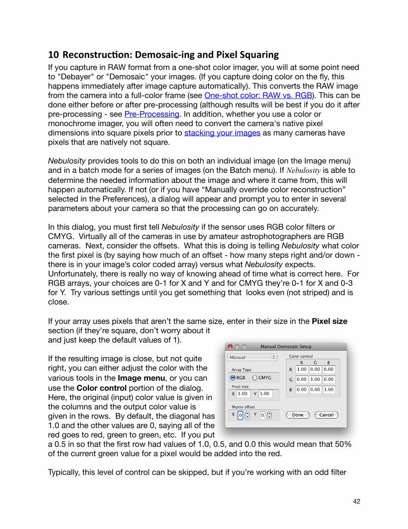
10 Reconstruc6on: Demosaic-‐ing and Pixel SquaringIf you capture in RAW format from a one-shot color imager, you will at some point need to "Debayer" or "Demosaic" your images. (If you capture doing color on the fly, this happens immediately after image capture automatically). This converts the RAW image from the camera into a full-color frame (see One-shot color: RAW vs. RGB). This can be done either before or after pre-processing (although results will be best if you do it after pre-processing - see Pre-Processing. In addition, whether you use a color or monochrome imager, you will often need to convert the camera's native pixel dimensions into square pixels prior to stacking your images as many cameras have pixels that are natively not square.
Nebulosity provides tools to do this on both an individual image (on the Image menu) and in a batch mode for a series of images (on the Batch menu). If Nebulosity is able to determine the needed information about the image and where it came from, this will happen automatically. If not (or if you have “Manually override color reconstruction” selected in the Preferences), a dialog will appear and prompt you to enter in several parameters about your camera so that the processing can go on accurately.
In this dialog, you must first tell Nebulosity if the sensor uses RGB color filters or CMYG. Virtually all of the cameras in use by amateur astrophotographers are RGB cameras. Next, consider the offsets. What this is doing is telling Nebulosity what color the first pixel is (by saying how much of an offset - how many steps right and/or down - there is in your image’s color coded array) versus what Nebulosity expects. Unfortunately, there is really no way of knowing ahead of time what is correct here. For RGB arrays, your choices are 0-1 for X and Y and for CMYG they’re 0-1 for X and 0-3 for Y. Try various settings until you get something that looks even (not striped) and is close.
If your array uses pixels that aren’t the same size, enter in their size in the Pixel size section (if they’re square, don’t worry about it and just keep the default values of 1).
If the resulting image is close, but not quite right, you can either adjust the color with the various tools in the Image menu, or you can use the Color control portion of the dialog. Here, the original (input) color value is given in the columns and the output color value is given in the rows. By default, the diagonal has 1.0 and the other values are 0, saying all of the red goes to red, green to green, etc. If you put a 0.5 in so that the first row had values of 1.0, 0.5, and 0.0 this would mean that 50% of the current green value for a pixel would be added into the red.
Typically, this level of control can be skipped, but if you’re working with an odd filter
42
setup or you’re working with CMYG arrays, this can be quite helpful. For example, if you’re using a Sony CMYG chip and Nebulosity does not recognize the sensor, once the offsets are in place, values of 1.06, 0.29, -0.41 in the first row, -0.4, 1.06, and 0.54 in the second row, and 0.50, -0.4, and 1.11 in the last row will give a reasonable color rendition by compensating for the chip’s imperfect color filters.
It is important to note that Nebulosity will automatically square the pixels during the debayer process for one-shot color images. Any color image is assumed to therefore have square pixels.
It is also important to note that if you use a Canon DSLR, ideal color balance in Nebulosity will be accomplished if you select the appropriate setting under "DSLR White Balance / IR Filter" in the Preferences dialog.
43
11 Previewing and Grading ImagesLet's face it. Some images just don't look good. Some of your shots may look great and some may look horrible. Maybe the tracking failed, maybe dew started to form, maybe you hit the scope or the wind blew. Who knows what, but some shots just aren't as good as others.
When stacking images you have the chance to skip any frame you don't like but this can be a bit too subjective at times. Nebulosity provides two ways to do this beforehand.
The first is to use the Preview Files command in the File menu. You can use this to load up a set of images and rename or delete ones you do not wish to use (you can also use this to blink between images). The second is a way to automatically grade each image in your set relative to each other image in the set to let you pick the best frames. In the Batch menu, you'll find an entry for Grade Image Quality. Select it and you'll be asked to choose the frames you want to grade.
Earlier versions of Nebulosity used an image-grading algorithm that graded the relative quality of images. That is, which images were the sharpest and which were the least sharp based on an assessment of what the edges looked like in the image. This has now been replaced with an algorithm that grades the absolute quality of the images.
For each image that is graded, a set of stars is identified and the same half flux radius (HFR) used during Fine Focus is calculated for these stars. The average HFR (times 100) is used as the filename post-grading. So, if you see an image called Q382_M51.fit after grading, the average half flux radius was 3.82 in that image.
44
12 LRGB Color SynthesisNebulosity allows you to synthesize a color image from separate frames. For example, users of monochrome cameras must take a set of images through red, green, and blue filters to create a color image. Users might also want to combine a full-color image from a one-shot color camera with a "luminance" frame taken from a monochrome camera, or to combine images taken through separate line filters. Nebulosity provides a tool for this.
To use the tool, you must first align all your images and save each frame (rather than the whole stack) using the Align and Combine tool. Co-register the images using any version of the Translation (+Rotation +(Scale)) tool you wish. You can do this on all the raw frames at once or you can do this on the stacks you’ve made for each color type (i.e., your processed red data, your processed green data, etc.)
Located in the Batch menu, the LRGB Color Synthesis tool can then be activated. Select your mode (RGB, Traditional LRGB, and Color Ratio LRGB) and frames. If you have a full-color file, you can load all 3 color planes at once using the "RGB frame" button. This will overwrite any red, green, or blue data you have already loaded. (You can load these first and then replace any color plane by loading another file into that color plane directly.) If you know ahead of time you wish to scale the color channels relative to each other, you can do so using the sliders.
12.1 RGB ModeIn RGB mode, 3 color channels are used and directly create a color image. It is the simplest mode.
12.2 LRGB: TradiAonal HSI ModeThis implements the traditional LRGB technique. The red, green, and blue frames are used to calculate a hue and saturation value at each pixel. The luminance (or intensity) value is replaced by the value provided by the luminance frame. The resulting HSI (or HSL) data are converted back into RGB in the output image. This is the traditional method, but can lead to a loss of saturation.
12.3 LRGB: Color RaAo ModeThis technique gives an alternative method of luminance layering that avoids the loss of color saturation by the traditional method. The RGB data are used to create R:L, G:L, and B:L ratios (L derived from RGB). The L component is then replaced by the value in the luminance frame and the image converted back to RGB.
45

13 Image Normaliza6on and Histogram MatchingIdeally, all frames taken under the same circumstances of the same target should all have the same intensity. Often, this is not the case as changes in light level, cloud cover, etc. can change the intensity from frame to frame. Further, if changes are made in the capture settings (e.g., different exposure durations), you're certainly going to have differences in overall image intensity across frames.
If you're doing the Average/Default method of stacking, you need not worry about this issue unless the changes are really quite severe. If you're using standard-deviation based stacking, Drizzle, or Colors in Motion, it is a good idea to normalize your images before stacking. What this will do is to get all of the frames to have roughly the same brightness by removing differences in the background brightness and scaling across frames.
There are two methods to normalize the images in Nebulosity.
1) The Normalize entry in the Batch menu will go through all selected frames and attempt to put them all in a common intensity range by taking care of offset and scaling differences across frames. After normalization, all frames should have their minimum at ~100 and their maximum at ~65535. Do this before you do any alignment of the frames (it can be done before or after pre-processing, but you don't want the black borders surrounding the image that can come in during alignment to throw off the normalization process.)
2) The Match Histogram entry in the Batch menu will ask you for a reference image and attempt to match the histograms for a set of target images to this reference image. It’s performing a more advanced stretch than you’d get in Normalize and can thereby be more effective. Note, if you’re using a one-shot color camera, do your demosaic before you try to use Match Histograms.
46
14 Stacking ImagesStacking multiple exposures is a fantastic thing to do for your images. If you can stack your images, you don't need to hold perfect tracking as long (making life easier) and you reduce any noise in your image that is not consistent from exposure to exposure (much of the noise is not). Thus, a stack of images will look less grainy (less noisy) than any one individual image. This lets you stretch and process the image more to bring out fainter details. All in all, stacking is a very good thing.
In Nebulosity, stacking can be done with or without alignment. For light frames (where stars are apt to move between each frame), you will want to align the images either prior to stacking or during stacking (see below). For things like dark frames, bias frames, and flat frames, you will not want to align the frames first.
14.1 Overview of TradiAonal Star-‐based AlignmentFew of us have perfect mounts that track or guide so well that there is no drift whatsoever across images. (In fact, it turns out to be better to have a bit of drift between images, as your image isn't always aligned with whatever consistent noise is in your camera, but this is a rather long topic not worth going into at the moment.) The net result of this is that if we were to stack a series of images atop each other as they came off the camera, we would end up with a blurred or streaky looking image. Each star was not in the same place in each image (the whole field of stars moved between images), so the result is quite poor.
In Nebulosity, this process is called "Align and Combine" and there are various options available to you (see below). In each, you are asked to find a star (or sometimes two) that is the same in each image. You will be asked to left-click on this common star (it is best to use a somewhat isolated and non-saturated star) in each image. Don't worry about being perfect in your clicking. Nebulosity will always search around the area where you clicked to find the star's centroid (i.e., it will refine your click automatically). In addition after the first image, Nebulosity will attempt to find the same star in each image for you and place a circle around that star.
If you wish to keep Nebulosity's location, simply Ctrl-click (Command-click on the Mac) anywhere in the image (if it gets it wrong, just click on the correct star). If you know you want to keep all of the images and your tracking was good enough that Nebulosity can find the star from frame to frame, an Alt-click will pretend you did a Ctrl-click on each frame and accept all frames. Finally, if you want to skip an image (e.g., if it was blurred), simply Shift-Click anywhere in the image and it will not be used in the stacking process.
Nebulosity provides several ways to align a series of images prior to or during stacking to take out this overall movement in the image. In the simplest method (Translation), Nebulosity will take out shifts between your images (a.k.a. translations) and average the aligned data. You do this by picking a common star in each image, and Nebulosity takes care of the rest, shifting each frame (by whole pixels, without "resampling"). This
47
works very well for equatorially-mounted telescopes (including fork-mounted scopes on a wedge). This does not work for Alt-Az mounted scopes. This style of mount makes stars not only move left/right and up/down but the entire field rotates as well.
A more complex technique, Colors in Motion, is also used for stacks that have shifts between images. Unlike the other techniques provided, Colors in Motion simultaneously aligns RAW images, stacks them, and reconstructs color information from one-shot color cameras. It cannot be used on RGB data or on black and white data.
To align and combine images using alt-az mounted scopes (or equatorially- mounted scopes), Nebulosity provides three other techniques. The first is similar to the above but allows for rotation and sub-pixel alignment. It is called Translation + Rotation. Related to this is Translation + Rotation + Scaling in which frames are allowed to be resized to align atop each other. To let Nebulosity know about the possible rotation, you must pick two stars in each image. Each image will be shifted and rotated to align them all prior to averaging the data.
The final technique that works on both equatorial and alt-az mounted scopes is called Drizzle (Align and Combine: Drizzle). Drizzle can not only combine images from alt-az (or equatorial) scopes, but it also enhances the resolution very well. To do this, you will again have to pick two stars in each image, and Nebulosity will do the rest.
14.2 CombinaAon methodsIn all of these, you have the option of using either strict averaging or adaptive stacking. In several (the Translation (+Rotation) (+Scaling)) you also have the option of saving each individual file post-alignment rather than saving the stack. This can be very useful, for example, in preparing frames taken through different filters for (L)RGB color synthesis or for using the Standard Deviation method of stacking.
14.2.1 Averaging vs. Adding vs. Adap5ve StackingDuring any of the Align and Combine methods, Nebulosity can mathematically stack images in one of two ways. By default, an Adaptive Stacking technique is used (see Preferences menu). Some people worry a great deal about whether to add (sum) or average their frames during the stacking process. Each technique has its ups and downs. If you have 3 images in which the same pixel reads 100, 100, and 101, summing gives you 301, whereas averaging gives you 100. Internally, in Nebulosity, the average would be 100.33333 (as it should be), but when saved, it would become 100 as the images are saved in "integers" (aka whole numbers, not "floats" which let you have fractional bits as well). This makes one think that adding is best, but another example shows the problem there.
Let's now say that a bright pixel reads 32000, 32010, and 32100 in our three images. The sum is 96110 here where the average is 32036.666. When saved, this would become 65535 if summing were used and 32037 if averaging were used. Let's have
48

another pixel - even brighter - reading 64000, 64010, and 64100 in the image. Once saved, the sum would make this 65535 and the average would make it 64037. Here, we see the problem with simple summing. You can saturate the image pretty easily, especially if you start with 16-bit images. Here, one pixel should be twice as bright as the other and yet it ends up equally bright (65535) if adding is used, since this is the highest possible value.
Nebulosity uses an Adaptive Stacking technique that avoids the weaknesses of both. It can be viewed as always being somewhere in between adding and averaging your data. The output (the stack) will always have a maximum value of ~65535 so that you are always using the full range of your data. This is enabled by default and for most uses will be optimal. (Note, it is not used when the Fixed Combine is selected as this tool is often used for dark frames). Unless you have a real reason to, you should leave this on (see Preferences menu). If you turn it off, Nebulosity will compute a straight average when stacking.
14.2.2 Standard Devia5on Based Stacking (Sigma-‐clip)If you were to take a perfect image of a target, each pixel would have its "ideal" or "true" value - how much intensity there is from that part of the target. The trouble is, each time we sample the target (take an image of the target), we record both that true value and some noise.
Averaging helps to get rid of this noise. It should tell us the central tendency and therefore estimate the truth. The more samples we have, the better the estimate is. But, if some samples are really abnormal ("outliers"), the average can get thrown off. For example if a hot pixel drifts into a patch of background sky, the average value will go up considerably and the hot pixel will show up in the stack (technically, of course, the stars and sky moved, not the hot pixel).
Standard Deviation (SD) based stacking gives us a way to identify these outliers and eliminate them prior to computing the average. To do this, we calculate not only the mean (average) of each pixel's value in the dataset but also a second statistic that describes how much variability there is around that mean. We calculate the standard deviation (the square root of the variance) and use this to filter out "bad" samples.
If we assume the data are "normal", about 70% of all samples will lie within one standard deviation of the mean (that is, 70% are less than one standard deviation above or one standard deviation below the average). About 95% like within 2 SD of the mean.
During SD stacking each (aligned) pixel, has the mean and standard deviation calculated across all of the images in the stack. If your SD threshold is at 1.5, any samples of that pixel that have an intensity beyond 1.5 SD from the mean are removed
Note: Another term used for this method is “sigma clipping” or “sigma clipped stacking”. Sigma is the Greek symbol typically used to refer to the standard deviation.
49
and a new average, excluding these samples, is calculated. This is why hot pixels are often eliminated using SD stacking - those hot pixel values are very abnormal and lie far away from the mean.
With the filter set at 1.75, it takes a more extreme or "outlying" intensity value to be counted as "bad" than at 1.5. At 2.0, it takes even more abnormal a value to be excluded. Thus, more samples go into the final image using a higher threshold (and more noise as well). Typically, filtering values at 1.5 or 1.75 will yield the best results.
To use Standard Deviation stacking, you must first Normalize your frames. Then, you must align your images using any of the Translation (+Rotation (+Scaling)) routines. Do this to all of your images and save each file rather than saving the average stack. Then, select "None" for alignment method and the various SD stacking choices will appear. Try 1.75 or 1.5 initially before using any more extreme values.
Note, that this requires a lot more memory than the more traditional techniques. If you’ve not got much memory and you’ve got very large images, expect this to take awhile.
14.3 Align and Combine OpAonsWhen aligning images to get them ready to stack, you’ve got a few options. Your choice comes down to asking yourself things like whether you need to account for rotation (e.g., your polar alignment isn’t great or the camera rotated between images). Let’s go through the various options here.
14.3.1 Align and Combine: FixedPositive nothing moved or want to see just how much it did move? Fixed may be your choice here. Running this will stack things without any alignment at all. At the very least, it’s useful (mandatory) for stacking any control frames like darks, flats, and biases.
14.3.2 Align and Combine: Transla5onThis is the most straightforward method of stacking. Each image is shifted up, down, left, and/or right by whole pixels prior to align it with all the other images prior to combining.
Once your images have been pre-processed, select Align and Combine: Translation from the Batch menu. You will then be presented with a dialog asking you what frames you wish to align. Select all of your pre-processed frames, even if you think a few you may not want to keep and press OK.
At this point, you'll notice the cursor has changed to a cross-hair (see below). You may also notice all of the menu items have gone grey, as you are now in alignment mode. The status bar shows your progress, telling you how many frames you've selected to align and how many you've done so far. Feel free to adjust the display levels or zoom
50
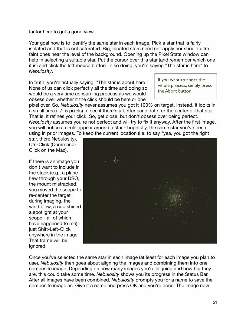
factor here to get a good view.
Your goal now is to identify the same star in each image. Pick a star that is fairly isolated and that is not saturated. Big, bloated stars need not apply nor should ultra-faint ones near the level of the background. Opening up the Pixel Stats window can help in selecting a suitable star. Put the cursor over this star (and remember which one it is) and click the left mouse button. In so doing, you're saying "The star is here" to Nebulosity.
In truth, you're actually saying, "The star is about here." None of us can click perfectly all the time and doing so would be a very time consuming process as we would obsess over whether it the click should be here or one pixel over. So, Nebulosity never assumes you got it 100% on target. Instead, it looks in a small area (+/- 5 pixels) to see if there's a better candidate for the center of that star. That is, it refines your click. So, get close, but don't obsess over being perfect. Nebulosity assumes you're not perfect and will try to fix it anyway. After the first image, you will notice a circle appear around a star - hopefully, the same star you've been using in prior images. To keep the current location (i.e. to say "yea, you got the right star, there Nebulosity), Ctrl-Click (Command-Click on the Mac).
If there is an image you don't want to include in the stack (e.g., a plane flew through your DSO, the mount mistracked, you moved the scope to re-center the target during imaging, the wind blew, a cop shined a spotlight at your scope - all of which have happened to me), just Shift-Left-Click anywhere in the image. That frame will be ignored.
Once you've selected the same star in each image (at least for each image you plan to use), Nebulosity then goes about aligning the images and combining them into one composite image. Depending on how many images you're aligning and how big they are, this could take some time. Nebulosity shows you its progress in the Status Bar. After all images have been combined, Nebulosity prompts you for a name to save the composite image as. Give it a name and press OK and you're done. The image now
If you want to abort the whole process, simply press the Abort button.
51
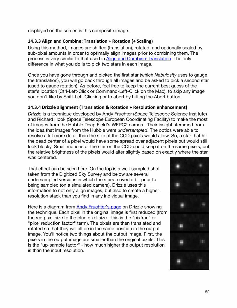
displayed on the screen is this composite image.
14.3.3 Align and Combine: Transla5on + Rota5on (+ Scaling)Using this method, images are shifted (translation), rotated, and optionally scaled by sub-pixel amounts in order to optimally align images prior to combining them. The process is very similar to that used in Align and Combine: Translation. The only difference in what you do is to pick two stars in each image.
Once you have gone through and picked the first star (which Nebulosity uses to gauge the translation), you will go back through all images and be asked to pick a second star (used to gauge rotation). As before, feel free to keep the current best guess of the star's location (Ctrl-Left-Click or Command-Left-Click on the Mac), to skip any image you don't like by Shift-Left-Clicking or to abort by hitting the Abort button.
14.3.4 Drizzle alignment (Transla5on & Rota5on + Resolu5on enhancement)Drizzle is a technique developed by Andy Fruchter (Space Telescope Science Institute) and Richard Hook (Space Telescope European Coordinating Facility) to make the most of images from the Hubble Deep Field's WFPC2 camera. Their insight stemmed from the idea that images from the Hubble were undersampled. The optics were able to resolve a lot more detail than the size of the CCD pixels would allow. So, a star that hit the dead center of a pixel would have some spread over adjacent pixels but would still look blocky. Small motions of the star on the CCD could keep it on the same pixels, but the relative brightness of the pixels would alter slightly based on exactly where the star was centered.
That effect can be seen here. On the top is a well-sampled shot taken from the Digitized Sky Survey and below are several undersampled versions in which the stars moved a bit prior to being sampled (on a simulated camera). Drizzle uses this information to not only align images, but also to create a higher resolution stack than you find in any individual image.
Here is a diagram from Andy Fruchter's page on Drizzle showing the technique. Each pixel in the original image is first reduced (from the red pixel size to the blue pixel size - this is the "pixfrac" or "pixel reduction factor" term). The pixels are then translated and rotated so that they will all be in the same position in the output image. You'll notice two things about the output image. First, the pixels in the output image are smaller than the original pixels. This is the "up-sample factor" - how much higher the output resolution is than the input resolution.
52
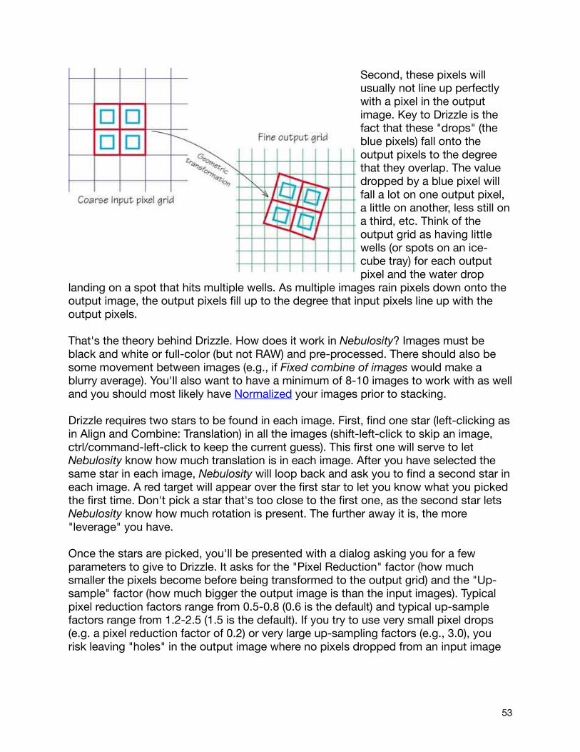
Second, these pixels will usually not line up perfectly with a pixel in the output image. Key to Drizzle is the fact that these "drops" (the blue pixels) fall onto the output pixels to the degree that they overlap. The value dropped by a blue pixel will fall a lot on one output pixel, a little on another, less still on a third, etc. Think of the output grid as having little wells (or spots on an ice-cube tray) for each output pixel and the water drop
landing on a spot that hits multiple wells. As multiple images rain pixels down onto the output image, the output pixels fill up to the degree that input pixels line up with the output pixels.
That's the theory behind Drizzle. How does it work in Nebulosity? Images must be black and white or full-color (but not RAW) and pre-processed. There should also be some movement between images (e.g., if Fixed combine of images would make a blurry average). You'll also want to have a minimum of 8-10 images to work with as well and you should most likely have Normalized your images prior to stacking.
Drizzle requires two stars to be found in each image. First, find one star (left-clicking as in Align and Combine: Translation) in all the images (shift-left-click to skip an image, ctrl/command-left-click to keep the current guess). This first one will serve to let Nebulosity know how much translation is in each image. After you have selected the same star in each image, Nebulosity will loop back and ask you to find a second star in each image. A red target will appear over the first star to let you know what you picked the first time. Don't pick a star that's too close to the first one, as the second star lets Nebulosity know how much rotation is present. The further away it is, the more "leverage" you have.
Once the stars are picked, you'll be presented with a dialog asking you for a few parameters to give to Drizzle. It asks for the "Pixel Reduction" factor (how much smaller the pixels become before being transformed to the output grid) and the "Up-sample" factor (how much bigger the output image is than the input images). Typical pixel reduction factors range from 0.5-0.8 (0.6 is the default) and typical up-sample factors range from 1.2-2.5 (1.5 is the default). If you try to use very small pixel drops (e.g. a pixel reduction factor of 0.2) or very large up-sampling factors (e.g., 3.0), you risk leaving "holes" in the output image where no pixels dropped from an input image
53
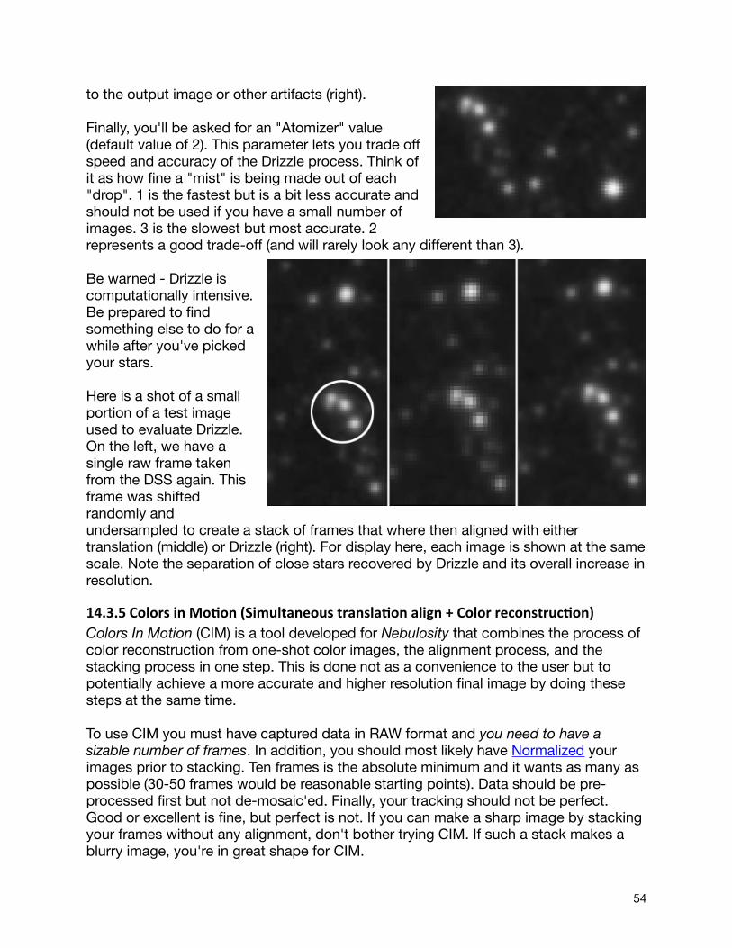
to the output image or other artifacts (right).
Finally, you'll be asked for an "Atomizer" value (default value of 2). This parameter lets you trade off speed and accuracy of the Drizzle process. Think of it as how fine a "mist" is being made out of each "drop". 1 is the fastest but is a bit less accurate and should not be used if you have a small number of images. 3 is the slowest but most accurate. 2 represents a good trade-off (and will rarely look any different than 3).
Be warned - Drizzle is computationally intensive. Be prepared to find something else to do for a while after you've picked your stars.
Here is a shot of a small portion of a test image used to evaluate Drizzle. On the left, we have a single raw frame taken from the DSS again. This frame was shifted randomly and undersampled to create a stack of frames that where then aligned with either translation (middle) or Drizzle (right). For display here, each image is shown at the same scale. Note the separation of close stars recovered by Drizzle and its overall increase in resolution.
14.3.5 Colors in Mo5on (Simultaneous transla5on align + Color reconstruc5on)Colors In Motion (CIM) is a tool developed for Nebulosity that combines the process of color reconstruction from one-shot color images, the alignment process, and the stacking process in one step. This is done not as a convenience to the user but to potentially achieve a more accurate and higher resolution final image by doing these steps at the same time.
To use CIM you must have captured data in RAW format and you need to have a sizable number of frames. In addition, you should most likely have Normalized your images prior to stacking. Ten frames is the absolute minimum and it wants as many as possible (30-50 frames would be reasonable starting points). Data should be pre-processed first but not de-mosaic'ed. Finally, your tracking should not be perfect. Good or excellent is fine, but perfect is not. If you can make a sharp image by stacking your frames without any alignment, don't bother trying CIM. If such a stack makes a blurry image, you're in great shape for CIM.
54
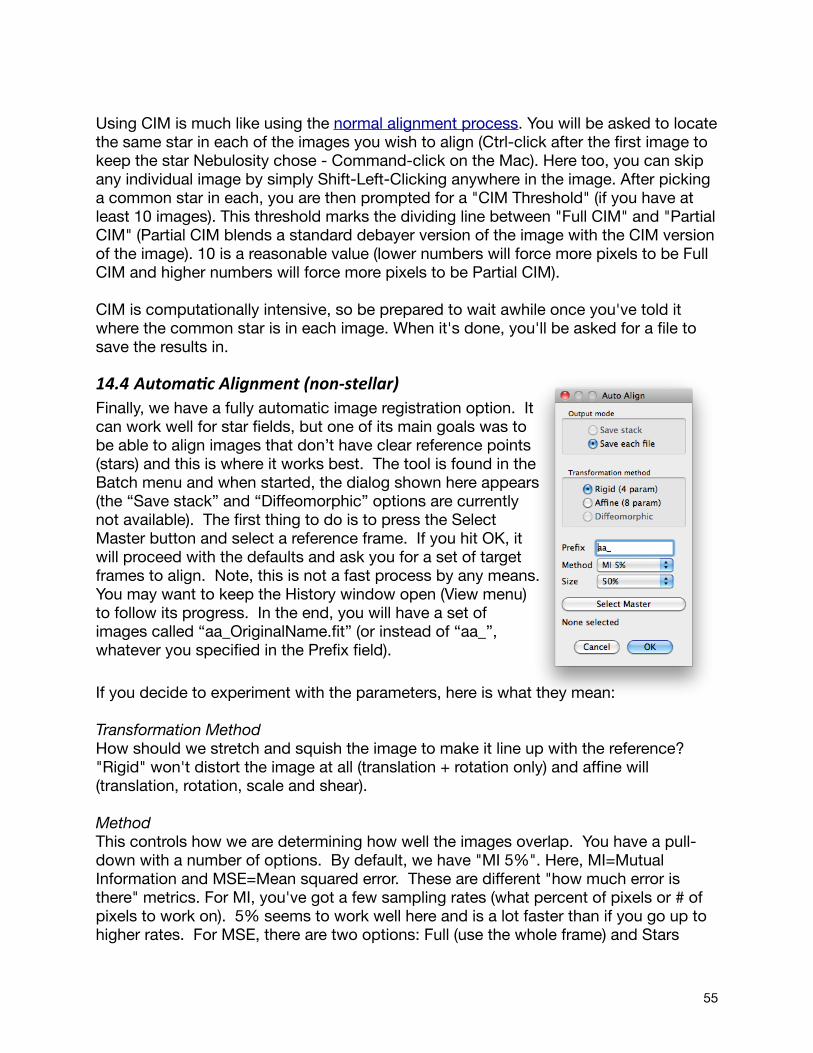
Using CIM is much like using the normal alignment process. You will be asked to locate the same star in each of the images you wish to align (Ctrl-click after the first image to keep the star Nebulosity chose - Command-click on the Mac). Here too, you can skip any individual image by simply Shift-Left-Clicking anywhere in the image. After picking a common star in each, you are then prompted for a "CIM Threshold" (if you have at least 10 images). This threshold marks the dividing line between "Full CIM" and "Partial CIM" (Partial CIM blends a standard debayer version of the image with the CIM version of the image). 10 is a reasonable value (lower numbers will force more pixels to be Full CIM and higher numbers will force more pixels to be Partial CIM).
CIM is computationally intensive, so be prepared to wait awhile once you've told it where the common star is in each image. When it's done, you'll be asked for a file to save the results in.
14.4 AutomaAc Alignment (non-‐stellar)Finally, we have a fully automatic image registration option. It can work well for star fields, but one of its main goals was to be able to align images that don’t have clear reference points (stars) and this is where it works best. The tool is found in the Batch menu and when started, the dialog shown here appears (the “Save stack” and “Diffeomorphic” options are currently not available). The first thing to do is to press the Select Master button and select a reference frame. If you hit OK, it will proceed with the defaults and ask you for a set of target frames to align. Note, this is not a fast process by any means. You may want to keep the History window open (View menu) to follow its progress. In the end, you will have a set of images called “aa_OriginalName.fit” (or instead of “aa_”, whatever you specified in the Prefix field).
If you decide to experiment with the parameters, here is what they mean:
Transformation Method How should we stretch and squish the image to make it line up with the reference? "Rigid" won't distort the image at all (translation + rotation only) and affine will (translation, rotation, scale and shear).
MethodThis controls how we are determining how well the images overlap. You have a pull-down with a number of options. By default, we have "MI 5%". Here, MI=Mutual Information and MSE=Mean squared error. These are different "how much error is there" metrics. For MI, you've got a few sampling rates (what percent of pixels or # of pixels to work on). 5% seems to work well here and is a lot faster than if you go up to higher rates. For MSE, there are two options: Full (use the whole frame) and Stars
55

(focus on things that look like stars). SizeThe amount of motion between frames can be accurately estimated without looking at the whole frame or without looking at it at full resolution. By default, Nebulosity downsamples the image to half size and runs on that to save time. You can run at full-size or at 25% size as well or focus on just the central 512 pixels.
56
15 Image AdjustmentWhile Nebulosity is not designed to be an advanced image processing application like PhotoShop or the GIMP, it does supply a number of purpose-built and very useful tools for adjusting your images (usually the result of stacking). These tools are located under the Image menu.
For any of these, if you decide you don't like the results, simply press Cancel or use the Undo command in the Image menu (or Ctrl-Z). By default you have 3 steps of Undo available, but with a quick trip to the Preferences menu, you can have unlimited Undos and Redos.
15.1 Demosaic’ing and Pixel squaringThe tools in this section are primarily aimed at one-shot color cameras. They let you convert the image into color (from a RAW Bayer-matrix grayscale image) or keep it as monochrome, but reconstruct it in ways optimized for various filters.
15.1.1 Demosaic ImageIf you captured a one-shot color image in RAW format and wish to see it in full-color, use this tool. It will reconstruct the raw image and turn it into a full-color image for viewing or saving. The algorithm used for this (there are several available) is set in your Preferences. There is also a Batch version of this tool that will allow you to demosaic a series of files. (Note, this should be done if you capture in RAW format after pre-processing but before alignment).
It is also important to note that if you use a Canon DSLR, ideal color balance in Nebulosity will be accomplished if you select the appropriate setting under "DSLR White Balance / IR Filter" in the Preferences dialog.
15.1.2 Square B&W If your sensor’s pixels are not square (i.e., they are a different height and width), you’ll probably want to square them after pre-processing. For one-shot color cameras this happens during the demosaic process. For black and white sensors, this happens here. As with the demosaic process, you have tools to do this on the current image and on a batch of images.
15.1.3 Reconstruc5ng Images from One-‐shot Color Cameras and Line FiltersIn a previous section (see Monochrome vs. Color?) a typical color filter array was shown for a one-shot color camera that uses red, green, and blue filters. If we place a "line filter" in front of such a camera, what happens? For example, suppose we placed an H-alpha filter in front of this array? Such filters pass light in a very narrow range, centered on 656nm of "Hydrogen alpha". Emission nebulae emit light specifically at this wavelength (and several others), so passing this light and block all else can lead to an excellent way to image nebulae amid light pollution and can lead to stunning images of these nebulae. When multiple lines are imaged separately (e.g. one frame of Ha, one
57

of O-III, etc) they can be combined into beautiful "false color" images.
Typically, such imaging has been reserved for monochrome cameras. The reason can be seen in that Bayer array. Photons that pass through the Ha filter are well into the red area of the spectrum. As such, only the red pixels will get any light. The green and blue pixels will be dark. Thus, we have only 25% of our pixels doing anything and the others are merely contributing noise. So, when reconstructing RAW data, one could take the RAW data and use the Low Noise 2x2 Bin or Adaptive 2x2 Bin tools. This would create an image half the size but would remove all evidence of the Bayer pattern. The one valid red pixel would be averaged with the three invalid pixels in a local 2x2 area and the result would be dominated by the red signal. One could also use the normal debayer routine and simply use the Discard Color tool. This is a common approach, but one that may not be optimal (see image below).
While we cannot escape the loss of resolution entirely, there are ways of improving how images are reconstructed on one-shot color cameras when line filters are used. For example, when CMYG color arrays are used instead of RGB arrays, more pixels respond to Ha light (as is shown by this shot with an Ha filter of the Horsehead nebula, courtesy of Michael Garvin). Knowing this, and knowing how the pixels respond to this light can let us optimize this reconstruction.
Nebulosity gives you several tools to do the reconstruction in addition to using the binning tools or the Discard Color tool. One is a "Generic" method that will do a good job on any line filter with any camera but is not optimized for any specific combination. A second is a reconstruction optimized for "nebula" filters and O-III filters that leak light in the Ha and beyond regions (e.g., Televue, Meade, and Lumicon filters). This is also a
58

rather generic reconstruction that will work well with a wide range of setups. Finally, for CMYG arrays, there are optimized reconstructions for Ha and pure O-III filters (e.g., Astronomik, Orion, and Custom Scientific) that do not leak light in Ha or higher wavelengths. A comparison of these techniques on the data from the Horsehead nebula taken on an Orion StarShoot's CMYG array is shown below.
In addition, this menu has options for pulling out each of the color channels directly for one-shot cameras with RGB sensors. Since the green pixels are twice as common as the red and blue, you have options to grab either of the green fields or to average this into a single green. Note, with these options, the image will be half the original’s size.
15.2 Geometric manipulaAonsThe tools in this section let you change the size of the image and its orientation.
15.2.1 CropUsually, after stacking a series of images, you end up with a dark border in your stacked frame. This is because Nebulosity had to move all the images around to get them to line up and some needed to be moved further than others. To get rid of these borders (or just to recompose your image), you can crop the image. One way to do so is to simply drag a selection using the left mouse. Start in one corner and hold the mouse button down to create a selection box and let go when the box is the desired size. Once happy with the box, pull down Crop from the Image menu and you'll have cropped in on just that area. A second way to do so is to pull down Crop from the Image menu and enter the number of pixels to crop off directly
15.2.2 Mirror / RotateNeed to rotate or mirror that image to get it to line up with something else (e.g., reality)? You can rotate 90 degrees clockwise or counter-clockwise, 180 degrees, or flip your image up/down or left/right. Note, there are batch versions of these tools as well.
15.2.3 BinningImages from some cameras are quite large and it can be useful to cut their size down (e.g., to post to the Web). Nebulosity lets you bin images 2x2, thus cutting the image size in half. An added benefit of binning is that by combining data from 4 pixels into one, noise is reduced (much in the same way it is with stacking). Finally, one additional use of binning 2x2 is to remove all color information from a RAW frame off a one-shot color camera. This turns the one-shot color camera into something a lot closer to a monochrome camera.
Nebulosity gives you 3 ways to bin your image. You can sum all 4 pixels (which will brighten the image considerably), average all 4 pixels (which will keep the same brightness) or perform an adaptive bin. The adaptive bin will combine the data in a way between the summation and averaging, optimizing the combination so that the full 0-65535 range is used.
59

15.2.4 ResizeWant your image to be rescaled (aka “resized”, aka “resampled”)? The Resize tool in the Image menu can make your image larger or smaller using a number of different resampling algorithms. Simply enter in the scaling factor (e.g. “2” to double the size of the image, “0.5” to make it half as big) and choose an algorithm.
Here, we have an image that was first reduced to half its size by binning and then restored to full size with the different algorithms available. “Box” is fast but ugly when increasing the size of the image. “Bilinear” is fast but will smooth the image a bit more than some of the others. “B-Spline” will lead to the smoothest output. “Lanczos sinc” can lead to the sharpest output but is more prone to ringing than “Catmull-Rom” or “Bicubic”. The Catmull-Rom usually outperforms the standard Bicubic.
15.3 Stretching and Intensity scalingThe tools in this section let you adjust the look of your image by stretching the contrast and by performing other transformations to the intensity of the image.
15.3.1 Levels / Power StretchThe Levels / Power Stretch tool is a very versatile and useful tool. Once you have combined a number of images, you'll likely notice that your sky is still bright and the DSO is quite possibly still dim. Overall, the combined shot looks little like the wonderful shots you see posted on the Internet, even by others with the same camera. The problem is that even though you've combined
If you want even more control over the values in these tools, double-click on the readout (Mac/Win) or on the slider (Mac) and you can specify values directly.
60
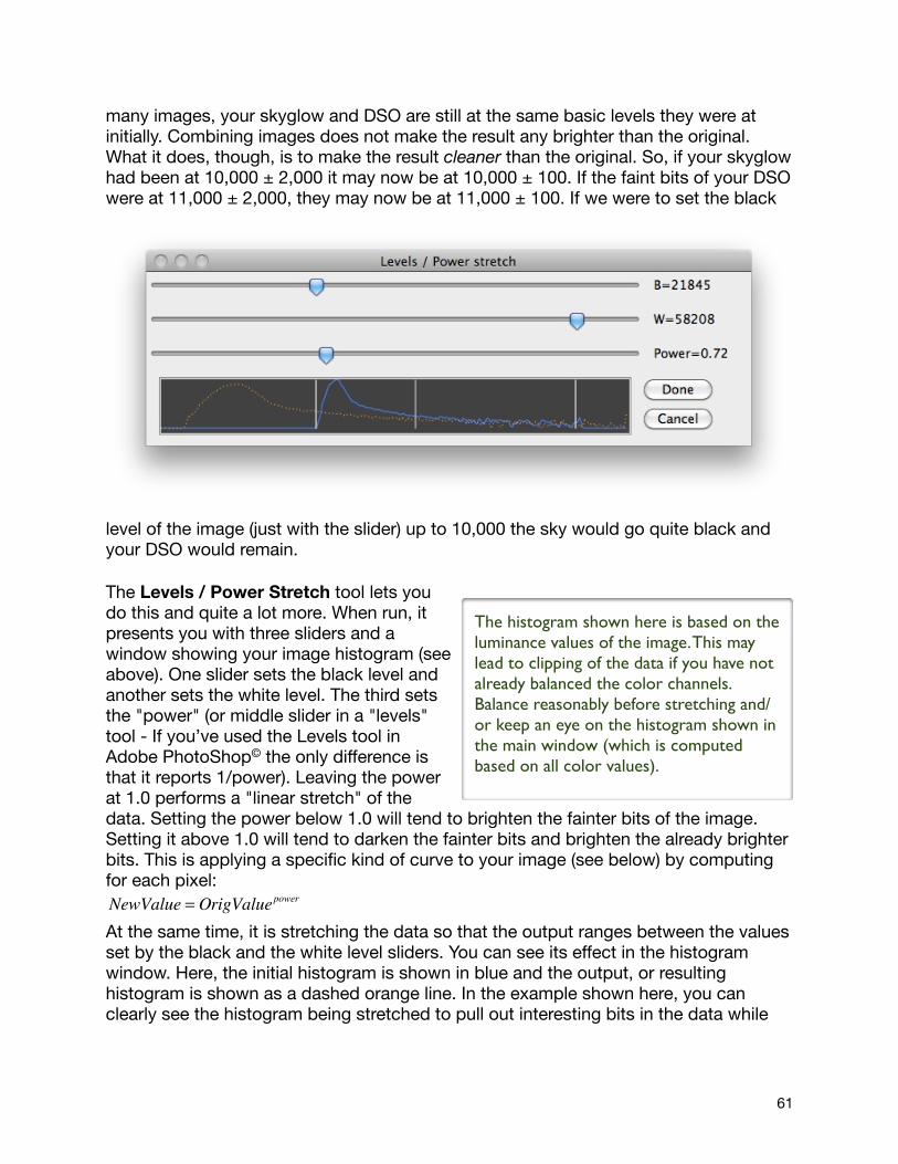
many images, your skyglow and DSO are still at the same basic levels they were at initially. Combining images does not make the result any brighter than the original. What it does, though, is to make the result cleaner than the original. So, if your skyglow had been at 10,000 ± 2,000 it may now be at 10,000 ± 100. If the faint bits of your DSO were at 11,000 ± 2,000, they may now be at 11,000 ± 100. If we were to set the black
level of the image (just with the slider) up to 10,000 the sky would go quite black and your DSO would remain.
The Levels / Power Stretch tool lets you do this and quite a lot more. When run, it presents you with three sliders and a window showing your image histogram (see above). One slider sets the black level and another sets the white level. The third sets the "power" (or middle slider in a "levels" tool - If you’ve used the Levels tool in Adobe PhotoShop© the only difference is that it reports 1/power). Leaving the power at 1.0 performs a "linear stretch" of the data. Setting the power below 1.0 will tend to brighten the fainter bits of the image. Setting it above 1.0 will tend to darken the fainter bits and brighten the already brighter bits. This is applying a specific kind of curve to your image (see below) by computing for each pixel: NewValue = OrigValuepower
At the same time, it is stretching the data so that the output ranges between the values set by the black and the white level sliders. You can see its effect in the histogram window. Here, the initial histogram is shown in blue and the output, or resulting histogram is shown as a dashed orange line. In the example shown here, you can clearly see the histogram being stretched to pull out interesting bits in the data while
The histogram shown here is based on the luminance values of the image. This may lead to clipping of the data if you have not already balanced the color channels. Balance reasonably before stretching and/or keep an eye on the histogram shown in the main window (which is computed based on all color values).
61
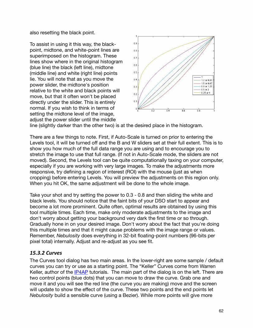
also resetting the black point.
To assist in using it this way, the black-point, midtone, and white-point lines are superimposed on the histogram. These lines show where in the original histogram (blue line) the black (left line), midtone (middle line) and white (right line) points lie. You will note that as you move the power slider, the midtone's position relative to the white and black points will move, but that it often won't be placed directly under the slider. This is entirely normal. If you wish to think in terms of setting the midtone level of the image, adjust the power slider until the middle line (slightly darker than the other two) is at the desired place in the histogram.
There are a few things to note. First, if Auto-Scale is turned on prior to entering the Levels tool, it will be turned off and the B and W sliders set at their full extent. This is to show you how much of the full data range you are using and to encourage you to stretch the image to use that full range. (If not in Auto-Scale mode, the sliders are not moved). Second, the Levels tool can be quite computationally taxing on your computer, especially if you are working with very large images. To make the adjustments more responsive, try defining a region of interest (ROI) with the mouse (just as when cropping) before entering Levels. You will preview the adjustments on this region only. When you hit OK, the same adjustment will be done to the whole image.
Take your shot and try setting the power to 0.3 - 0.8 and then sliding the white and black levels. You should notice that the faint bits of your DSO start to appear and become a lot more prominent. Quite often, optimal results are obtained by using this tool multiple times. Each time, make only moderate adjustments to the image and don't worry about getting your background very dark the first time or so through. Gradually hone in on your desired image. Don't worry about the fact that you're doing this multiple times and that it might cause problems with the image range or values. Remember, Nebulosity does everything in 32-bit floating-point numbers (96-bits per pixel total) internally. Adjust and re-adjust as you see fit.
15.3.2 Curves The Curves tool dialog has two main areas. In the lower-right are some sample / default curves you can try or use as a starting point. The “Keller” Curves come from Warren Keller, author of the IP4AP tutorials. The main part of the dialog is on the left. There are two control points (blue dots) that you can move to draw the curve. Grab one and move it and you will see the red line (the curve you are making) move and the screen will update to show the effect of the curve. These two points and the end points let Nebulosity build a sensible curve (using a Bezier). While more points will give more
62
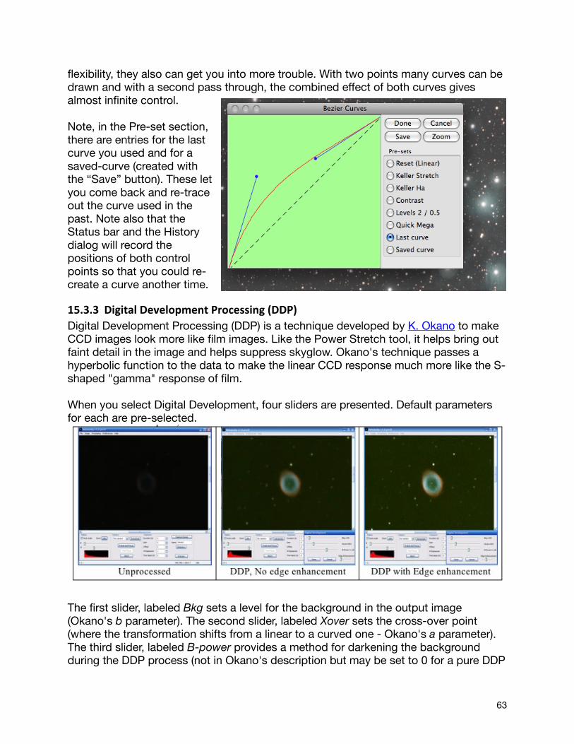
flexibility, they also can get you into more trouble. With two points many curves can be drawn and with a second pass through, the combined effect of both curves gives almost infinite control.
Note, in the Pre-set section, there are entries for the last curve you used and for a saved-curve (created with the “Save” button). These let you come back and re-trace out the curve used in the past. Note also that the Status bar and the History dialog will record the positions of both control points so that you could re-create a curve another time.
15.3.3 Digital Development Processing (DDP)Digital Development Processing (DDP) is a technique developed by K. Okano to make CCD images look more like film images. Like the Power Stretch tool, it helps bring out faint detail in the image and helps suppress skyglow. Okano's technique passes a hyperbolic function to the data to make the linear CCD response much more like the S-shaped "gamma" response of film.
When you select Digital Development, four sliders are presented. Default parameters for each are pre-selected.
The first slider, labeled Bkg sets a level for the background in the output image (Okano's b parameter). The second slider, labeled Xover sets the cross-over point (where the transformation shifts from a linear to a curved one - Okano's a parameter). The third slider, labeled B-power provides a method for darkening the background during the DDP process (not in Okano's description but may be set to 0 for a pure DDP
63
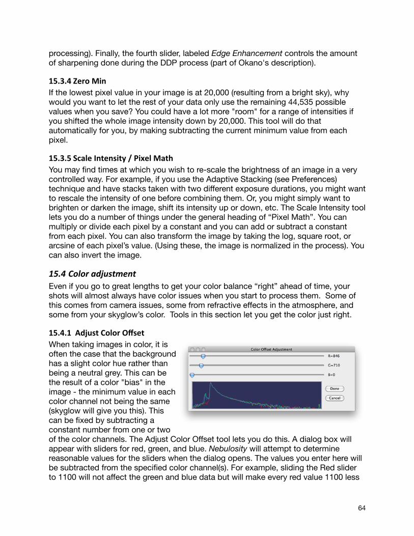
processing). Finally, the fourth slider, labeled Edge Enhancement controls the amount of sharpening done during the DDP process (part of Okano's description).
15.3.4 Zero MinIf the lowest pixel value in your image is at 20,000 (resulting from a bright sky), why would you want to let the rest of your data only use the remaining 44,535 possible values when you save? You could have a lot more "room" for a range of intensities if you shifted the whole image intensity down by 20,000. This tool will do that automatically for you, by making subtracting the current minimum value from each pixel.
15.3.5 Scale Intensity / Pixel MathYou may find times at which you wish to re-scale the brightness of an image in a very controlled way. For example, if you use the Adaptive Stacking (see Preferences) technique and have stacks taken with two different exposure durations, you might want to rescale the intensity of one before combining them. Or, you might simply want to brighten or darken the image, shift its intensity up or down, etc. The Scale Intensity tool lets you do a number of things under the general heading of “Pixel Math”. You can multiply or divide each pixel by a constant and you can add or subtract a constant from each pixel. You can also transform the image by taking the log, square root, or arcsine of each pixel’s value. (Using these, the image is normalized in the process). You can also invert the image.
15.4 Color adjustmentEven if you go to great lengths to get your color balance “right” ahead of time, your shots will almost always have color issues when you start to process them. Some of this comes from camera issues, some from refractive effects in the atmosphere, and some from your skyglow’s color. Tools in this section let you get the color just right.
15.4.1 Adjust Color OffsetWhen taking images in color, it is often the case that the background has a slight color hue rather than being a neutral grey. This can be the result of a color "bias" in the image - the minimum value in each color channel not being the same (skyglow will give you this). This can be fixed by subtracting a constant number from one or two of the color channels. The Adjust Color Offset tool lets you do this. A dialog box will appear with sliders for red, green, and blue. Nebulosity will attempt to determine reasonable values for the sliders when the dialog opens. The values you enter here will be subtracted from the specified color channel(s). For example, sliding the Red slider to 1100 will not affect the green and blue data but will make every red value 1100 less
64

than it was previously. A 3-color histogram is shown below the sliders to help in getting the offset just right. Aim to have the left edge of the histograms similar for all three colors. Pressing Cancel will revert back to the original image.
15.4.2 Adjust Color ScalingIn color imaging, it is often the case also that your color channels are not balanced in their scaling either. This is particularly true in using separate color filters in a black and white camera (if one does not perfectly adjust exposure duration to compensate for the varying transmission of color filters and for the CCD's varying sensitivity to different colors) but can occur in a one-shot color camera as well. The Adjust Color Scaling tool lets you rescale the intensity of individual color channels much like the Scale Intensity tool lets you rescale the intensity of the entire image. Setting the Green slider to 1.05 would, for example, multiply the intensity of each pixel's green component by 1.05. A 3-color histogram is shown below the sliders to help in getting the offset just right. Aim to get the histograms similar in size to color balance the image. Pressing Cancel will revert back to the original image.
15.4.3 Auto Color BalanceRather than running the color offset and scaling tools (above) separately, you can have Nebulosity automatically stretch and scale the channels to fix global color casts (it does this by the same histogram matching routine used to normalize images’ histograms to a reference image).
15.4.4 Hue / Satura5onWhile the color of your image can be adjusted by scaling each color channel separately you can often have better control over it when making “by eye” adjustments using the Hue, Saturation, and Luminance tool. Hue gives you control over the overall color shade, saturation gives you control over how rich the colors appear, and luminance gives you control over how bright the image is.
15.4.5 Discard Color and Convert to ColorAt times, one may want to take a color image and strip it of all color information. This can be useful, for example, if you want to make a luminance (L) channel for image processing outside of Nebulosity or for using during pre-processing of monochrome images. The Discard Color tool does just this, converting your color image into a monochrome image (the average RGB value is used). The Convert to Color does the converse. It takes a mono image and makes it into an RGB image (with every pixel having R=G=B).
15.4.6 LRGB Color Synthesis ToolThis tool lets you combine separate L (optional), R, G, and B frames into a color image. It is described in detail here.
15.5 Sharpening, Blurring, and Noise ReducAonAfter processing our images, its usually necessary to perform some kind of sharpening
65
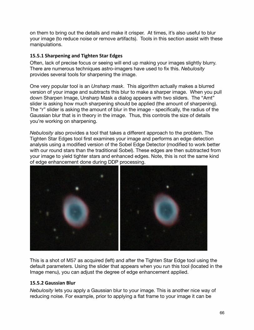
on them to bring out the details and make it crisper. At times, it’s also useful to blur your image (to reduce noise or remove artifacts). Tools in this section assist with these manipulations.
15.5.1 Sharpening and Tighten Star EdgesOften, lack of precise focus or seeing will end up making your images slightly blurry. There are numerous techniques astro-imagers have used to fix this. Nebulosity provides several tools for sharpening the image.
One very popular tool is an Unsharp mask. This algorithm actually makes a blurred version of your image and subtracts this blur to make a sharper image. When you pull down Sharpen Image, Unsharp Mask a dialog appears with two sliders. The “Amt” slider is asking how much sharpening should be applied (the amount of sharpening). The “r” slider is asking the amount of blur in the image - specifically, the radius of the Gaussian blur that is in theory in the image. Thus, this controls the size of details you’re working on sharpening.
Nebulosity also provides a tool that takes a different approach to the problem. The Tighten Star Edges tool first examines your image and performs an edge detection analysis using a modified version of the Sobel Edge Detector (modified to work better with our round stars than the traditional Sobel). These edges are then subtracted from your image to yield tighter stars and enhanced edges. Note, this is not the same kind of edge enhancement done during DDP processing.
This is a shot of M57 as acquired (left) and after the Tighten Star Edge tool using the default parameters. Using the slider that appears when you run this tool (located in the Image menu), you can adjust the degree of edge enhancement applied.
15.5.2 Gaussian BlurNebulosity lets you apply a Gaussian blur to your image. This is another nice way of reducing noise. For example, prior to applying a flat frame to your image it can be
66
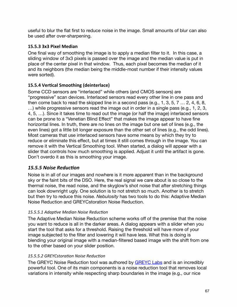
useful to blur the flat first to reduce noise in the image. Small amounts of blur can also be used after over-sharpening.
15.5.3 3x3 Pixel MedianOne final way of smoothing the image is to apply a median filter to it. In this case, a sliding window of 3x3 pixels is passed over the image and the median value is put in place of the center pixel in that window. Thus, each pixel becomes the median of it and its neighbors (the median being the middle-most number if their intensity values were sorted).
15.5.4 Ver5cal Smoothing (deinterlace)Some CCD sensors are “interlaced” while others (and CMOS sensors) are “progressive” scan devices. Interlaced sensors read every other line in one pass and then come back to read the skipped line in a second pass (e.g., 1, 3, 5, 7 … 2, 4, 6, 8, …) while progressive sensors read the image out in order in a single pass (e.g., 1, 2, 3, 4, 5, …). Since it takes time to read out the image (or half the image) interlaced sensors can be prone to a “Venetian Blind Effect” that makes the image appear to have fine horizontal lines. In truth, there are no lines on the image but one set of lines (e.g., the even lines) got a little bit longer exposure than the other set of lines (e.g., the odd lines). Most cameras that use interlaced sensors have some means by which they try to reduce or eliminate this effect, but at times it still comes through in the image. You can remove it with the Vertical Smoothing tool. When started, a dialog will appear with a slider that controls how much smoothing is applied. Adjust it until the artifact is gone. Don’t overdo it as this is smoothing your image.
15.5.5 Noise ReducAonNoise is in all of our images and nowhere is it more apparent than in the background sky or the faint bits of the DSO. Here, the real signal we care about is so close to the thermal noise, the read noise, and the skyglow’s shot noise that after stretching things can look downright ugly. One solution is to not stretch so much. Another is to stretch but then try to reduce this noise. Nebulosity has two tools to do this: Adaptive Median Noise Reduction and GREYCstoration Noise Reduction.
15.5.5.1 AdapGve Median Noise ReducGonThe Adaptive Median Noise Reduction scheme works off of the premise that the noise you want to reduce is all in the darker areas. A dialog appears with a slider when you start the tool that asks for a threshold. Raising the threshold will have more of your image subjected to the filter and lowering it will have less. What this is doing is blending your original image with a median-filtered based image with the shift from one to the other based on your slider position.
15.5.5.2 GREYCstoraGon Noise ReducGonThe GREYC Noise Reduction tool was authored by GREYC Labs and is an incredibly powerful tool. One of its main components is a noise reduction tool that removes local variations in intensity while respecting sharp boundaries in the image (e.g., our nice
67
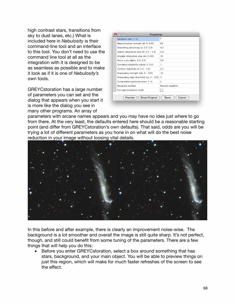
high contrast stars, transitions from sky to dust lanes, etc.) What is included here in Nebulosity is their command-line tool and an interface to this tool. You don’t need to use the command line tool at all as the integration with it is designed to be as seamless as possible and to make it look as if it is one of Nebulosity’s own tools.
GREYCstoration has a large number of parameters you can set and the dialog that appears when you start it is more like the dialog you see in many other programs. An array of parameters with arcane names appears and you may have no idea just where to go from there. At the very least, the defaults entered here should be a reasonable starting point (and differ from GREYCstoration’s own defaults). That said, odds are you will be trying a lot of different parameters as you hone in on what will do the best noise reduction in your image without loosing vital details.
In this before and after example, there is clearly an improvement noise-wise. The background is a lot smoother and overall the image is still quite sharp. It’s not perfect, though, and still could benefit from some tuning of the parameters. There are a few things that will help you do this:
• Before you enter GREYCstoration, select a box around something that has stars, background, and your main object. You will be able to preview things on just this region, which will make for much faster refreshes of the screen to see the effect.
68
• On entering GREYCstoration or after a change in parameters, hit the Preview button to see the effect. You can hit the Show Original button to revert the display back to the original image to see what was gained and what was lost. You can change parameters as much as you like hitting Preview between each iteration. Preview always goes back to the original data. Hitting Done will apply this to the whole image (and can take a long time – watch the title bar).
• Read the GREYCstoration documentation with examples.• The “Fast approximation” and nearest neighbor resample methods do speed
things up but don’t produce the best output.
Watch this space for more details of maximizing GREYCstoration’s effectiveness.
69
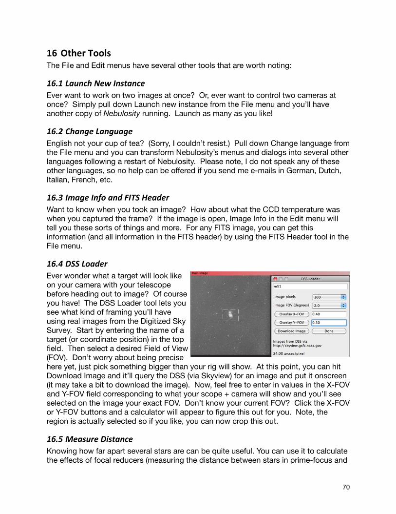
16 Other ToolsThe File and Edit menus have several other tools that are worth noting:
16.1 Launch New InstanceEver want to work on two images at once? Or, ever want to control two cameras at once? Simply pull down Launch new instance from the File menu and you’ll have another copy of Nebulosity running. Launch as many as you like!
16.2 Change LanguageEnglish not your cup of tea? (Sorry, I couldn’t resist.) Pull down Change language from the File menu and you can transform Nebulosity’s menus and dialogs into several other languages following a restart of Nebulosity. Please note, I do not speak any of these other languages, so no help can be offered if you send me e-mails in German, Dutch, Italian, French, etc.
16.3 Image Info and FITS HeaderWant to know when you took an image? How about what the CCD temperature was when you captured the frame? If the image is open, Image Info in the Edit menu will tell you these sorts of things and more. For any FITS image, you can get this information (and all information in the FITS header) by using the FITS Header tool in the File menu.
16.4 DSS LoaderEver wonder what a target will look like on your camera with your telescope before heading out to image? Of course you have! The DSS Loader tool lets you see what kind of framing you’ll have using real images from the Digitized Sky Survey. Start by entering the name of a target (or coordinate position) in the top field. Then select a desired Field of View (FOV). Don’t worry about being precise here yet, just pick something bigger than your rig will show. At this point, you can hit Download Image and it’ll query the DSS (via Skyview) for an image and put it onscreen (it may take a bit to download the image). Now, feel free to enter in values in the X-FOV and Y-FOV field corresponding to what your scope + camera will show and you’ll see selected on the image your exact FOV. Don’t know your current FOV? Click the X-FOV or Y-FOV buttons and a calculator will appear to figure this out for you. Note, the region is actually selected so if you like, you can now crop this out.
16.5 Measure DistanceKnowing how far apart several stars are can be quite useful. You can use it to calculate the effects of focal reducers (measuring the distance between stars in prime-focus and
70
reduced images) or to say, "Hey is this pair of stars on my image really that pair of stars in the atlas?" The Measure Distance tool lets you do this.
First, select up to 3 stars in your image by simply right-clicking on them in the image. The first will get a red circle around it, the second a green, and the third a blue. If you make an error, either Shift-R-Click to erase all points or keep selecting stars (you'll cycle back to red after blue). Next, pull down Measure Distance from the Image menu. You'll be asked for the resolution of the image in arc-seconds per pixel. (If you don't know, simply use 1.0 as a value and all values will be in CCD pixels or see use the calculator built into the DSS Loader tool or the formula shown in Your Telescope). A window will then appear showing you the distance from red to green and, if three points were selected, green to blue and red to blue.
16.6 Check / Update LicenseIf, for some reason, you need to update your license code or see what your license code is, this entry in the Edit menu will let you do so.
71
17 Supported CamerasNebulosity supports a wide range of cameras on both Windows and OS X. They are:
1. Canon DIGIC II, III, and 4 DSLRs (Windows and OS X): EOS 1100D/T3, 1000D/Rebel XS, 450D/Rebel XSi, 400D/Digital Rebel XTi, 500D/T1i, 550D/T2i, 600D/T3i, 350D/Digital Rebel XT, 60D, 50D, 40D, 30D, 20D/20Da, 5D Mark II, 5D, 7D, 1D Mark IIV, 1D Mark III, 1D Mark II N, 1D Mark II, 1Ds Mark III and 1Ds Mark II. See below for more details.
2. Fishcamp Starfish 3. Meade DSI, DSI Pro, DSI II, DSI II Pro, DSI III, and DSI III Pro.4. QSI 500 and 600 series 5. QHY8 6. SBIG (See below for more details) 7. Starlight Xpress SXV / SXVF / SXVR USB cameras (See below for more details)
In addition, on Windows, the following cameras are supported 1. Apogee Alta2. Atik 16 series (all) / Artemis 429/285 cameras 3. Atik “Universal” (3xx, 4xx, 4000, 11000, etc). 4. CCD Labs Q285M / QHY2Pro5. FLI 6. Moravian G2/G3 (v3 firmware or higher) 7. QHY8 Pro8. QHY99. Opticstar DS-335, DS-336C, DS-145, DS-142, and PL-130 10.Orion StarShoot Deep-Space Color Imager (Other Starshoot cameras supported
via ASCOM)11.SAC10 12.SAC7 / SC1 long-exposure modified webcams / Atik 1 and Atik 2 cameras. See
below for more details13.Any camera with an ASCOM v5/v6 driver (See below for more details)
17.1 SBIGAlmost all SBIG cameras are supported by using SBIG's Universal Driver (some very old ones are not supported by this driver and therefore not supported in Nebulosity). This must be installed first (see SBIG's website if you have not already used SBIG's software on your computer). On Windows and OS X, USB and Ethernet versions are supported. On Windows, but not OS X, parallel port models are supported. Note, however, that if you SBIG is a dual-chip model, the guide chip will not be available to any other program when the camera is in use in Nebulosity.
17.2 Starlight XpressWhile older USB-1 based Starlight Xpress cameras are not supported, all USB-2 based cameras (i.e., the "SXV" and later cameras) are supported.
72
The "Fast" mode available on the M (and MX) cameras is enganged whenever "High Speed mode" is selected in the Advanced Panel. On these cameras, short exposures are done via the "Interlaced" mode and longer exposures (generally ~1s or longer) are done via the "Progressive" mode.
If you have an older parallel-port camera, you can convert it to an SXVF version via Starlight Xpress’ USB2 converter box. Nebulosity will detect and use cameras that have this device attached.
17.3 Canon DIGIC II, III, & 4 DSLRsThe Canon DIGIC II, III, and 4-based DLSRs are supported in Nebulosity on both the Windows and Mac OS X platforms via Canon’s EDSDK (software development kit). Note, older DIGIC I-based cameras (D30/60, 1D, 10D, and 300D) are not supported by their EDSDK and therefore not supported in Nebulosity. Also note that Canon does not support all of their cameras under Windows 7 and is phasing out support of older cameras by the EDSDK (notably the DIGIC II based cameras like the Rebel 350).
The supported DSLRs act much as any one-shot color astronomical camera would in Nebulosity. This can cause confusion for people when they first try to capture images. Images will come up looking monochrome, the interface on the camera always says “busy”, they get FITS files rather than CR2 files, and their white balance settings don’t seem to have any effect. What the...?
Some of these things can be changed in the Preferences, but some cannot. What you can’t change is setup this way for a reason, however. It will say “busy” as Nebulosity has locked the camera and is preventing you from doing things like changing the shutter speed or the ISO value. When you want to change these, you change them in the Nebulosity interface (exposure time and gain / ISO) so Nebulosity knows these values. Likewise, it will ignore your white balance settings (as skyglow will throw the color balance off anyway - see below). It also won’t let you select JPEG or RAW directly, but it will do so as needed based on what you’re doing. When you hit Preview or Capture Series, it will take a RAW frame. When you hit Frame and Focus and Fine Focus, it will shift into a JPEG mode for high speed (but lower quality) readouts - just the kind of thing you want when trying to compose or focus.
17.3.1 Color images and FITS/CR2Just like any one-shot color camera, you can opt to acquire images in pure RAW (Bayer-matrix images that have not been converted to color yet), or in RGB via the Preferences. Here, you can choose whether you wish to optimize speed (high-quality JPEG images are downloaded from the camera) or quality (the RAW image is downloaded, the Bayer matrix extracted, and Nebulosity's Demosiac routines are applied). RAW Bayer-matrix images are the best choice when the highest quality is desired as they allow you to pre-process the images before conversion into color, and the color conversion (Demosaicing) is done using Nebulosity's best routines.
73
One thing to note here is what we mean by the term “RAW”. Some people feel that “RAW” means “CR2” or “NEF” or “CRW” format. These formats are just containers for image data. FITS is another container for image data as is TIFF or PNG or JPEG. All of these except JPEG can save the full 16-bit, pure data off the sensor with no loss whatsoever. “RAW” is just that - the raw sensor data. It has nothing to do with the container format per se.
By default, Nebulosity saves images from your DSLR in FITS format. It saves the raw sensor data in this container rather than in CR2, CRW, or whatever is the native format for your camera. But, fear not, it is storing the raw sensor data. It just doesn’t store things like the focal length setting of the zoom lens (that’s probably not hooked up to the camera since you’re probably shooting through a telescope). (Aside - it’s not like CR2 isn’t odd in it’s own right. It’s a lossless JPEG-compressed bit-packed image stored inside a massive TIFF-like hierarchy.) If you want CR2 files, though, you do have an option to save them in addition to the FITS files. Preferences, DSLR Save location will let you choose Computer (FITS only), Computer FITS and CR2, and even to save them on the CF card.
17.3.2 White balanceOne cannot read a setting on the camera that lets you know if the camera uses a stock IR filter or if it has been modified to have an extended-IR response (e.g. using a Baader IR filter or a Huetech filter). Color reconstruction must be done differently if an extended-IR filter is used, however. To ensure accurate color, make sure you have made the appropriate selection in the Preferences, Processing, DSLR White balance / IR filter section. If you’re not sure which one is correct, try taking a normal daytime shot (a CR2 file shot of something outdoors with your DSLR lens is just fine) and try the various options until you find one that gives a good color balance. Note, that if you see pink cores to saturated areas, try the Straight Color Scale option. Keep in mind that skyglow, atmospheric refraction, etc. will always muck with your colors, so there is no need to get this spot-on. Every night will have a bit different color and every time you, like all other imagers, will need to work the color balance.
17.3.3 Long exposures / bulb triggersCanon DSLRs can be classified into several generations based on the DIGIC processor used inside. With the advent of the DIGIC III and 4 DSLRs (circa 2007 and beyond), the cameras can take exposures of any length via a special “bulb” command. By default, Nebulosity will try to use these commands when you connect to a Canon DSLR (“DIGIC III onboard” in the Preferences - see below). The only downside to this arrangement is that you cannot use mirror lockup if you are using this method for long exposures.
Older, DIGIC II DLSRs (e.g., 350 XT) are limited to 30s exposures when the camera's internal timing is used. If you connect the USB cable to the camera and your computer
74
and this is your only connection, you will be limited to 30 seconds of exposure. To achieve longer exposures, some form of "bulb adapter cable" is required . Various forms of this exist to drive the camera's "bulb" setting from USB, serial, or parallel ports on your computer. If you use one of these to allow you longer exposures you must also keep the USB data cable connected (i.e. you will have two cables connected).
In the Preferences menu, you will find options to let you choose your long-exposure cable setup. Nebulosity supports the following:
• ShoeString DSUSB or DSUSB2 USB adapter (PC and Mac) • Serial port adapters (COM1-8) such as Hap Griffen's (PC and Mac) • Parallel port adapters (Pin 2 or Pin 3 on ports 0x378, 0x278, and 0x3BC) such as
Hap Griffen's (PC only) • Onboard "blulb" timing for DIGIC III and 4 DSLRs (default)
Note: Not all USB->Serial adapters will work as we need direct control over several data pins on the serial port. Generally, those that require a driver disk will be more likely to work (tested with inexpensive Prolific-based adapters and Keyspan adapters).
17.3.4 Mirror lockupThe Canon cameras all support a mirror-lockup mode. When enabled, pressing the shutter button once lifts the mirror and pressing it a second time triggers the exposure. Enabling this mode involves entering your camera's Tools menu and finding the appropriate Custom Function (CFn) - usually either 12 or 7, selecting and enabling this prior to connecting to the camera in Nebulosity. Nebulosity has no way to set this mode itself, but it can detect if the camera is in mirror-lockup mode and, if so, will send the appropriate shutter pulse prior to the main exposure.
Unfortunately, if using the onboard "bulb" mode for DIGIC III or 4 DSLRs, you cannot use the mirror lockup mode. There is no way to trigger a lockup over the USB line. Thus, for mirror-lockup mode to be used, you must have a long-exposure cable selected and attached. Another consequence of this is that mirror-lockup cannot be used in USB-only mode.
17.3.5 Mode dials and lens seingsNebulosity will attempt to read the current setting of your camera’s mode dial and inform you if it is set improperly. For most cameras (those without a “B” setting on the mode dial), the proper setting is “M” on the mode dial and if you have a DSLR lens attached, it should be in the “MF” position. Nebulosity will program the camera and use the onboard timing for short (<30 s) exposures and use whatever long-exposure adapter (including the onboard DIGIC III/4) for longer exposures.
Select your long-exposure adapter prior to connecting to the camera. Nebulosity attempts to connect to the long-exposure adapter when it connects to the camera itself.
75

For cameras with a “B” setting on the mode dial (e.g., the 5D Mk II), things get a bit more complex. On these cameras, if you want >30 s exposures, you must set the camera to the “B” position on the mode dial. Unfortunately, we cannot program short exposures in this mode. We can manually time short exposures, but you will never get a precise 1/1000 s exposure this way. To get precise timing for short exposures, have the camera in the “M” mode. As with the other cameras, any attached lens should be set to “MF”.
Note also, that onboard noise reduction (automatic dark frame collection and extraction) should be turned off. You are better off with a set of darks to combine and subtract from your lights than a single dark. Your final SNR will be substantially better if you do this and use that time imaging than if you take a single dark and subtract it after each image.
17.3.6 Troubleshoo5ng Connec5onsThere are several steps to take to ensure Nebulosity will connect to your camera.
1. Ensure that the USB data cable is connected (in addition to any long-exposure "bulb" cable) and that the camera did not decide to shut itself off from inactivity (once connected, Nebulosity will keep it turned on)
2. Ensure that your camera drivers (from the Canon CD) have been installed on your computer.
3. Verify that the EOS utility is installed and that it connects to the camera and can be used to control the camera.
4. Ensure that the camera is set to communicate (Menu, Tools, Communication) to the computer in "PC Connection" mode.
17.4 ASCOM CamerasNebulosity supports image capture through ASCOM v5/v6-compliant cameras under Windows. This means that any camera with an ASCOM camera driver can be used with Nebulosity, thus greatly expanding the number of cameras that can be used.
There are several things to know about ASCOM cameras, however.1. For your ASCOM-compliant camera to work, you must install both the ASCOM
platform itself (www.ascom-standards.org) and the specific driver for your camera.
2. When you attempt to connect to an ASCOM camera, an ASCOM dialog (the “Chooser”) will appear. This is not a Nebulosity dialog, but one of ASCOM’s. If your camera is not listed in there, your camera driver is not properly installed. Consult your camera maker or the author of the driver for assistance. If the ASCOM “Chooser” does not appear, ASCOM itself is not properly installed.
3. In Nebulosity v2, there were two styles of ASCOM connections corresponding to the two ways ASOCM v5 let you talk to the camera: “early” and “late” binding. The meaning of this is too arcane for users here and ASCOM dropped “early” binding. Here in Nebulosity 3, all binding is “late”.
76
4. Not all of your camera’s features may be present. ASCOM’s camera driver specification may not include features unique to your camera.
17.5 SAC7 and Long Exposure WebcamsThe SAC7 and other cameras based on long-exposure modifications to webcams according to the work of Steve Chambers (otherwise known as "SC-modified" webcams) are supported in Nebulosity. There are a few things to note, however.
First, these cameras can either be used directly when attached to a parallel port (you'll need to know the "port number") or via a USB port. Many modern computers lack a parallel port or only include one that is derived from an internal USB-Parallel adapter. Unfortunately, these adapters do not make the right signals for the cameras to operate. ShoeString Astronomy has devised an excellent solution with their "LXUSB" product. This plugs into a USB port and, when controlled by Nebulosity, will make signals that can be used to fully control these cameras. Thus, cameras like the SAC7 can now be used on machines that only have USB ports and that do not have a parallel port at all!
Second, these cameras typically have two modes - a "short exposure" mode and a "long exposure" mode. In short exposure mode, the camera's own controls adjust the exposure duration (typically 1/25th of a second or shorter) via a pop-up window. In long exposure mode, the program (such as Nebulosity) controls the exposure duration.
In Nebulosity, short exposure mode is selected by setting the exposure duration to 0. Anything greater than zero will put the camera into long exposure mode. In short exposure mode, the shutter speed is controlled via a pop-up window. Press the Advanced button in the Camera panel and you'll get a slightly different version of the Advanced dialog described above. You'll find Setup and Format buttons that let you configure the resolution, shutter speed, gain, frame rate, etc.
Note: For the best images in both short and long exposure modes, always set the frame rate to a low setting such as 5 FPS. This minimizes the amount of compression your images undergo. Do this in the Advanced Dialog using the Setup and Format buttons
In addition to these buttons, the Advanced Dialog has one added section for these cameras. A "Read delay" can be entered. The default value should work on most systems but if you find you are dropping frames, try adjusting this value (5 ms increments will be good). System speed and specifics of your camera may dictate a slightly different value (10ms - 30ms for a typical range).
17.6 Camera Advanced PanelIf you click on the Advanced button in the Camera panel, a dialog box will appear that lets you set various advanced controls on the camera. Some of the options may be grayed out or not even present. If so, this means either that the current camera does not support this feature or that some other feature is preventing it from being activated.
77
Below is a description of the available options.• Amp off: Checking this box will have the CCD camera's amplifier turned off
during the exposure. This amplifier, when on causes "amp glow" - a brightening usually in one corner of the image. Rarely would you ever want to uncheck this box.
• Double Read: This option enables a feature designed to fix the "interlacing artifact" found on interline transfer CCDs like the SAC10 and Orion StarShoot. You'll notice each exposure takes twice as long but that you end up with a smoother image. This option is particularly useful for shorter exposures where the problem is worse (4 seconds of read time is a lot in comparison to a 2 second exposure but not much in comparison to a 5 minute exposure). If you're working with bright objects or short exposures, you'll want to use this or the VBE option.
• High speed read: If selected, the camera will read the image off the CCD more rapidly but at the expense of increasing the noise. This is enabled by default during Frame and Focus but is not to be used for DSO imaging. Selecting both High speed read and Double Read is an excellent way to take good planetary or lunar shots.
• Bin mode: Selecting this option will put the camera into a binned mode whereby pixels are combined during the CCD readout itself. This increases sensitivity at the cost of resolution and, at times, at the cost of color on one-shot color cameras. The available bin modes depend on your particular camera.
• Enable TEC: You can set the cooler on your camera to a certain temperature (if the camera supports this)
• Close shutter: If you want to take dark frames, setting this will keep the shutter on your camera closed (if your camera supports this).
• Oversample: If selected the camera will sample and convert the information from the CCD twice. The net result is a less noisy image, but one that takes a bit longer to read and process.
• VBE balance color exp times: (SAC10 only) This feature attempts to fix the same problem addressed by the Double Read option (the problem is sometimes called the Venetian Blind Effect), but to do so with a single exposure. It intelligently balances the intensity of the odd and even lines and can be quite useful for shorter exposures.
78
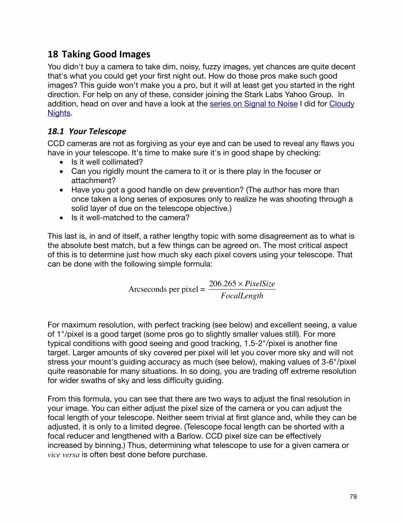
18 Taking Good ImagesYou didn't buy a camera to take dim, noisy, fuzzy images, yet chances are quite decent that's what you could get your first night out. How do those pros make such good images? This guide won't make you a pro, but it will at least get you started in the right direction. For help on any of these, consider joining the Stark Labs Yahoo Group. In addition, head on over and have a look at the series on Signal to Noise I did for Cloudy Nights.
18.1 Your TelescopeCCD cameras are not as forgiving as your eye and can be used to reveal any flaws you have in your telescope. It's time to make sure it's in good shape by checking:
• Is it well collimated? • Can you rigidly mount the camera to it or is there play in the focuser or
attachment? • Have you got a good handle on dew prevention? (The author has more than
once taken a long series of exposures only to realize he was shooting through a solid layer of due on the telescope objective.)
• Is it well-matched to the camera?
This last is, in and of itself, a rather lengthy topic with some disagreement as to what is the absolute best match, but a few things can be agreed on. The most critical aspect of this is to determine just how much sky each pixel covers using your telescope. That can be done with the following simple formula:
For maximum resolution, with perfect tracking (see below) and excellent seeing, a value of 1"/pixel is a good target (some pros go to slightly smaller values still). For more typical conditions with good seeing and good tracking, 1.5-2"/pixel is another fine target. Larger amounts of sky covered per pixel will let you cover more sky and will not stress your mount's guiding accuracy as much (see below), making values of 3-6"/pixel quite reasonable for many situations. In so doing, you are trading off extreme resolution for wider swaths of sky and less difficulty guiding.
From this formula, you can see that there are two ways to adjust the final resolution in your image. You can either adjust the pixel size of the camera or you can adjust the focal length of your telescope. Neither seem trivial at first glance and, while they can be adjusted, it is only to a limited degree. (Telescope focal length can be shorted with a focal reducer and lengthened with a Barlow. CCD pixel size can be effectively increased by binning.) Thus, determining what telescope to use for a given camera or vice versa is often best done before purchase.
Arcseconds per pixel = 206.265 × PixelSizeFocalLength
79

18.2 Your MountA number of aspects about your mount will affect the quality of your images. Here, we'll talk about accurate polar alignment and about periodic error and guiding.
Note: To see how much your mount is moving between images, right-click on a star to lay down a "target" circle around it. This target will remain in the same place on the image across captures, and let you see how far that star has moved.
18.2.1 Polar AlignmentIf you've got an equatorial mount, aiming at Polaris with the RA and DEC zeroed will get you somewhat close to polar alignment but not close enough for imaging. Using a polar alignment scope on your equatorial mount or using your GOTO mount's alignment procedure will get you closer. But, neither will get you spot-on enough for long-exposure work. To do that, you've got two main options:
1) Drift alignment. In this technique, you watch how stars drift through the field and adjust your mount accordingly. For a standard equatorial mount, this is your best bet. It takes a bit of practice, but, once you know what you're doing, it'll take about 30 minutes to get a decent drift alignment - decent enough for the kind of exposures you'll be able to do without guiding anyway. Others have done a good job describing the technique, including a site by Pete Kennett or one by Scott Tucker of Starizona.
2) Iterative alignment. If you have a GOTO scope, you owe it to yourself to learn how to do this. I can get a nice alignment that won't drift (well, periodic error of course, but no overall drift) for an hour worth of imaging in about 5-10 minutes of work. There are several sites on the web that go over the method (e.g., Michael Covington's), but the basic idea is very simple.
First, do a "one star" alignment - the kind in which the scope aims itself towards where Polaris should be (using the Kochab clock if that makes sense to you) and then asks you to adjust the mount physically to center Polaris. After centering Polaris, the scope slews over to a single star and asks you to use the keypad controls to center that other star. At this point, you're close and have done the standard "one star" alignment.
Now, tell the scope to GOTO Polaris. Adjust the mount physically to remove about half the error between where it ended up and where Polaris actually is (i.e., have it aim to the spot about halfway between the GOTO and Polaris). Now, do a GOTO back to your alignment star, center, and SYNC to that star. Repeat a few times until your GOTOs on Polaris end up without any error and you're good to go!
18.2.2 Periodic Error and GuidingNow that your scope is polar aligned, the stars won't drift across the field on average. You'll still notice that they will rock back and forth a bit - sometimes very slowly and sometimes in abrupt jumps. This is called periodic error and caused by minor imperfections in your mount's worm gear - a cylindrical gear that actually turns the
80
telescope to counteract the earth's rotation. No worm gear is perfect, but some have bigger problems than others. If you don't choose to guide your telescope during imaging, these imperfections will limit how long you'll be able to expose each image. Exactly how long you can go will depend on the size of the periodic error and the amount of sky covered by each CCD pixel. Wide-angle shots with 10"/pixel are a lot more tolerant of periodic error than zoomed-in shots at 1"/pixel.
Some amateurs run shots unguided and end up stacking many 15-40s long exposures into one long image. With enough images, and with the right exposure settings (see below), this can be used to make very nice images.
But, what can you do to lengthen this time or to fix the problem entirely? Several mounts offer Periodic Error Correction (PEC). On these mounts, you train the telescope to know what the error is like by following a single star and correcting the errors using the telescope's controller. The mount then learns these corrections and applies them automatically. This can reduce the error quite a bit.
A second technique, often used on its own or in conjunction with periodic error correction is guiding. Here, an image of a star is sent to either an eyepiece (manual guiding) or a second camera (autoguiding) while your main imaging camera collects pictures. Two approaches are taken. In one, an Off-Axis Guider is used to split some of the light away from the main camera and towards this eyepiece or second camera. A small prism is placed so that the light split off is light that would not have fallen on your main imaging camera anyway. In a second, another telescope (a guide telescope) is attached to the imaging telescope. In both, this second view of a star is used to determine when the telescope is drifting slightly off target and to correct this problem by sending very small movement commands to the mount.
Many packages are out there to help you autoguide your mount. A free one from Stark Labs, PHD Guiding, works well on a wide range of cameras and mounts and is designed to be "Push Here Dummy" simple. Its goal is to make it so that you have little excuse for not trying autoguiding.
18.3 FocusGetting your camera sharply focused is critical to taking good pictures. The Frame and Focus routine will get you close, but will often not get you to as sharp a focus as you could get. For this, you'll want to make sure you're using the full Preview mode or the Fine Focus mode, making only small adjustments to your focus between each shot.
You can evaluate your focus by simple visual inspection or by calculating several statistics about a star. In particular, when a star is in focus, it will get more of its light on a central CCD pixel than when out of focus. The Fine Focus tool offers an excellent focus aid that will help you achieve critical focus.
In addition to these techniques, there are a few others you can try. One technique is to build or buy a Hartman Mask, a diffraction mask, or a Bahtinov Mask. They're not
81
tough to build - many consist of cutouts in pieces of cardboard and one is assembled out of TinkerToys (no, really). All work by having you place something in front of the scope during focusing. When the star is nice and sharp, the artifacts induced by each disappear or form a particular pattern. The Bahtinov mask is an exceptionally easy to use version and is very effective.
A second technique to try is to use the fact that in focus stars get more of their light on the CCD than out of focus stars. When in focus, you'll be able to see stars in the Preview or even Frame and Focus that would disappear when out of focus. Adjust the exposure duration or gain until you can just barely see a star. Adjust the focus to see if you can make it brighter or if it disappears on either side of where you are right now (or, if you know you're a bit out, make the star disappear with the duration or gain and reappear with the focus knob).
18.4 Exposure sefngsWhen taking images, there are a few simple rules to follow that will let you collect frames that can be used to make a nice final picture.
18.4.1 Rule #1: Use the Histogram to keep your background above the floor and bright bits below the ceiling.
First, you should always try to expose images so that the background sky is "off the floor" and the stars (or at least the cores of the DSOs) are "off the ceiling". What this means is that you don't want large parts of your image to have values of zero or of 65535 (the minimum and maximum possible values). Any time a pixel has either of these values, we've lost information. For example, let's say a star is at 65535 and one next to it is really twice as bright. Both get recorded at 65535 and the final image doesn't show a difference between the two. Once we've reached this maximum, we simply can't go any higher and so important details (such as the difference between these stars) are lost.
The same holds true on the dim end. Let's say a faint arm of a galaxy is just barely brighter than the skyglow around it (a very common situation). If your background sky is recorded as zero, quite possibly the faint bit of the galaxy is at zero as well. No matter how many images you stack, if they all have zero in them, you'll never be able to find that dim galaxy arm in your image.
How do you do this? The exposure duration is the most obvious method. Longer exposures will brighten the image (moving the histogram to the right). In addition, the increasing the gain and offset controls will also brighten the image. Both will add more noise into the image, but a little bit more noise is a lot better to have than ultra-black backgrounds. If you're running unguided images, you'll likely use higher values of gain and offset than those running guided.
82

18.4.2 Rule #2: Take lots of imagesEvery image you take has noise in it. So, adding images together adds noise into the image, right? Yes and no. If you compare a stack of 20 exposures of 30-second each to one exposure of 10 minutes, the single longer exposure will quite probably be a cleaner looking shot. But, if you compare one of the 30-second long images to the combination of all 20 exposures, the combination or "stack" of images will have a lot less noise in it than the single frame.
Why is this? Much of the noise in our images is uncorrelated or white noise. What this means is that each time we sample something (e.g., each time we take an image), we get some noise added into the image that has nothing to do with the amount of noise added in the last time we took the image. (Hot pixels and readout noise are examples of correlated noise and are addressed in dark frames and bias frames respectively).
When we combine multiple images, this uncorrelated noise starts to disappear. Four 30-second exposures will have half the noise of a single 30-second exposure (noise follows a 1/sqrt(N) function where N is the number of images you combine). One hundred such frames will have one tenth as much noise (and therefore 10x the SNR). Reducing the noise allows one to "stretch" the image to make a very fine distinction between dim portions of a DSO and the skyglow that is just the tiniest bit darker than the DSO (this will always be the case - its just a question of how small that difference is.)
18.4.3 Rule #3: Don't over-‐tax your mountIf your mount can only take exposures of 30-seconds before showing tracking errors on most exposures, don't try going any longer than 30-seconds until you can guide your mount (PHD Guiding from Stark Labs is free and tries to make this as painless as possible). Take Rule #1 and Rule #2 to heart and gather many noisier shots. Each one may look pretty bad and it may look like you'll never get a good image out of your efforts. Don't despair. I've had many nice shots come out of raw frames that look like noise with barely a hint of any DSO in there much less a nice smooth one.
18.4.4 What do gain and offset do? After coming off the CCD and before hitting the actual analog-digital-converter (ADC) to turn the signal into a number, there is typically a small pre-amplifier (this may be inside the ADC chip itself). What this preamp does is allow you to boost the signal by some variable amount and to shift the signal up by some variable amount. The boosting is called gain and the shift is called offset.
So, let's say that you have pixels that would correspond to 0.1, 0.2, 1.1, and 1.0 ADU were the ADC able to deal with fractional numbers. Now, given that it's not, this would turn into 0, 0, 1, and 1 ADU. Two bad things have happened. First, the 0.1 and 0.2 have become the same number and the 1.1 and 1.0 have become the same number. We've distorted the truth and failed to accurately represent subtle changes in intensity. This failure is called quantization error. Second, the first two have become 0 and, as noted
83

above, 0 is an evil black hole of information.
Well, what if we scaled these up by 10x before converting them into numbers (i.e., we introduce some gain)? We'd get 1, 2, 11, and 10. Hey, now we're getting somewhere! With gain alone, we've actually fixed both problems. In reality, the situation is often different and the ADC's threshold for moving from 0 to 1 might be high enough so that it takes a good number of electrons to move from 0 to 1. This is where injecting an offset (a DC voltage) into the signal comes in to make sure that all signals you could possibly have coming off the CCD turn into a number other than zero.
18.4.5 Gain's downside: Bit depth and dynamic range From the above example, it would seem like we should all run with lots of gain. The more the better! Heck, it makes the picture brighter too! I often get questions about this with the assumption that gain is making the camera more sensitive. It's not. Gain does not make your camera more sensitive. It boosts the noise as well as the signal and does not help the signal to noise ratio (SNR) in and of itself. Gain trades off dynamic range and quantization error.
We saw above how it reduces quantization error. By boosting the signal we can have fractional differences become whole-number differences. What's this about dynamic range?
Let's come up with another example. Let's have one camera with a gain of 1. So, 1 e-/ADU. Let's have another run at 0.5 e-/ADU. Now, let's have a pixel with 1k e-, another with 10k e-, another at 30k e-, and another at 50k e-. In our 1 e-/ADU cam, we of course have intensities of 1000, 10000, 30000, and 50000. In our 0.5 e-/ADU cam, we have intensities of 2000, 20000, 60000, and 65535. What? Why not 100000? Well, our 16-bit camera has a fixed limit of 65535. Anything above that gets clipped off. So while the 1 e-/ADU camera can faithfully preserve this whole range, the 0.5 e-/ADU camera can't. Its dynamic range is limited now.
18.4.6 How do manufacturers determine gain and offset for cameras that don't allow the user to adjust them?
Let's pretend we're making a real-world camera now and put in some real numbers and see how these play out. Let's look at a Kodak KAI-2020 sensor, for example. The chip has a well-depth specified at 45k e-. So, if we want to stick 45,000 intensity values into a range of 0-65,535, one easy way to do it is to set the gain at 45,000 / 65535 or at 0.69 e-/ADU. Guess what the SBIG ST-2000 (which uses this chip) has the gain fixed at... 0.6 e-/ADU. How about the QSI 520ci? 0.8 e-/ADU. As 45k e- is a target value with actual chips varying a bit, the two makers have chosen to set things up a bit differently to deal with this variation (SBIG's will clip the top end off as it's going non-linear a bit more readily), but both are in the same range and both fix the value.
Why? There's no real point in letting users adjust this. Let's say we let users control the gain and they set it to 5 e-/ADU. Well, with 45k e- for a maximum electron count at 5
84

e-/ADU, we end up with a max of 9,000 ADU and we induce strong quantization error. 10, 11, 12, 13 and 14 e- would all become the same value of 2 ADU in the image, loosing the detail you so desperately want. What if the user set it the other way to 0.1 e-/ADU? Well, you'd turn those electron counts into 100, 110, 120, 130, and 140 ADU and wonder just what's the point of skipping 10 ADU per electron. You'd also make 6553 e- be the effective full-well capacity of the chip. So, 6535:1 would be the maximum dynamic range rather than 45000:1. Oops. That nice detail in the core of the galaxy will have been blown out and saturated. You could have kept it preserved and not lost a darn thing (since each electron counts for > 1 ADU) if you'd left the gain at ~0.7 e-/ADU.
What about offset? Well, it's easy enough to figure out the minimum value a chip is going to produce and add enough offset in the ADC process to keep it such that this is never going to hit 0.
85

19 Menu Quick Reference
19.1 File Menu• Open File: Loads any FITS (color or B&W, compressed or not, 8-64 bits,
integers, floating points, you name it), PNG, TIFF, JPG, BMP, or DSLR RAW (CR2, CRW, NEF, etc.) file into memory and display. 8-bit/color files are automatically stretched to full range.
• Preview Files: Opens a dialog that lets you preview a set of files, deleting and renaming them as desired. Useful for filtering images and for quick looks at files.
• DSS Loader: Download an image from the Digitized Sky Survey and overlay an FOV indicator to help you plan your shots.
• FITS Header Tool: Lets you view the contents of the header of a FITS file.• Save current file (FITS): Saves the currently displayed image in FITS format
using 16-bit integers (0-65,535). Compression set by Preferences, Save as compressed FITS.
• Save BMP file as displayed: Saves the currently displayed image in Windows BMP (bitmap) format. The values of the black and white sliders set the black and white levels in this, since BMP format is only 8-bits / color. How it looks is how it will save.
• Save JPG file as displayed: Like Save BMP, but in JPEG format. Any JPEG quality / compression (0-100) factor possible.
• Save 16-bit/color TIFF: Saves the current image in TIFF format (lossless compressed or uncompressed) at full 16-bit/color (aka 48-bit color) bit depth. This preserves all information in your image for use in graphics programs
• Save 16-bit/color PNG: Saves the current image in PNG format (always lossless compression) at full 16-bit/color (aka 48-bit color) bit depth. This preserves all information in your image for use in graphics programs
• Save 16-bit/color PPM/PGM/PNM: Saves the current image in the appropriate variant of these “portable pixel map” UNIX-based standard formats.
• Save Color Components: Saves the current color frame as three separate FITS files corresponding to the the red, green, and blue components of the image.
• Launch new instance: Launches a separate running copy of Nebulosity to let you work on another image or control another camera.
• Change language: Changes the language used in the user-interface. You must restart Nebulosity after this.
• Exit: Exit the program (on Macs, in the Nebulosity menu)
19.2 Edit Menu• Undo: Undo the last change to your image. Undo will let you step back from any
changes made by tools in the Image menu. By default, you can take 3 steps back. You can opt to disable Undo in the Preferences menu (to run a bit faster) or to have virtually unlimited undo capability.
• Redo: Think you liked it better with that processing you just undid? Redo. • Image Info: Shows information about the current image including its size and the
various capture parameters that either were stored in the FITS header or will be
86
stored when the image is saved. • Measure Distance: Measure the distance in CCD pixels, arc-seconds, and arc-
minutes among up to 3 points in the image (right-click to set points first). • Edit / Create Script: Open a window that allows you to create a capture script
and load / edit an existing script. • Run Script: Run a capture script, automating the image capture process • De-select cameras: Camera pull-down getting a bit cumbersome? Use this to
remove entries from the list (you can always add them back in later).• Check / Update License: Verify your current license code and status and/or
update your license code.• Preferences: Set various preferences. See Preferences. (On Macs, in the
Nebulosity menu)
19.3 Batch Menu (see also the Pre-‐Processing secAon)• Pre-process image sets: Apply traditional dark frame or bad pixel maps, flat
frame, and bias frame corrections to correct for typical CCD artifacts. Apply these corrections to a series of images.
• Make Bad Pixel Map: Create a map of the bad pixels on your CCD. • Batch Demosaic + Square RAW Color and Batch Square BW: Batch versions of
the tools found in the Image menu. • Grade Image Quality: Grade a set of images to determine the sharpest (and
fuzziest) of the set. • Normalize Intensities: Normalize all images in a set to remove offset and scaling
differences. • Match Histograms: Equate a set of images’ histograms to match that of a target
image.• Align and Combine: Align and (optionally) combine a series of images. A dialog
will appear to let you control the method. Methods include: Fixed (no alignment), Translation ("one star", full-pixel shifts), Translation + Rotation (subpixel, including rotation such as with an alt-az mount), Translation + Rotation + Scaling (same, but including a scaling term), Drizzle, and Colors in Motion. For Fixed alignment, Standard Deviation based stacking is an option.
• Automatic Alignment (non-stellar): Automatically align frames without picking reference stars.
• Batch Geometry: Batch versions of rotation, binning, resampling and cropping.• Batch Conversion: Tools to convert a set of images from FITS to various
graphics formats or vice versa.• Batch One-shot Color with Line Filters: Batch versions of the tools in the Image
menu that extract portions of the color filter array.
19.4 Image Menu (see also the Image Adjustment secAon)• De-Mosaic RAW + Square: Convert a single RAW CCD image currently
displayed from a one-shot color camera into a full-color image. Faster and better quality modes available.
• Square B&W pixels: Squares pixels from black and white images.
87
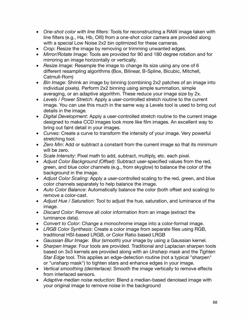
• One-shot color with line filters: Tools for reconstructing a RAW image taken with line filters (e.g., Ha, Hb, OIII) from a one-shot color camera are provided along with a special Low Noise 2x2 bin optimized for these cameras.
• Crop: Resize the image by removing or trimming unwanted edges. • Mirror/Rotate Image: Tools are provided for 90 and 180 degree rotation and for
mirroring an image horizontally or vertically. • Resize Image: Resample the image to change its size using any one of 6
different resampling algorithms (Box, Bilinear, B-Spline, Bicubic, Mitchell, Catmull-Rom)
• Bin Image: Shrink an image by binning (combining 2x2 patches of an image into individual pixels). Perform 2x2 binning using simple summation, simple averaging, or an adaptive algorithm. These reduce your image size by 2x.
• Levels / Power Stretch: Apply a user-controlled stretch routine to the current image. You can use this much in the same way a Levels tool is used to bring out details in the image.
• Digital Development: Apply a user-controlled stretch routine to the current image designed to make CCD images look more like film images. An excellent way to bring out faint detail in your images.
• Curves: Create a curve to transform the intensity of your image. Very powerful stretching tool.
• Zero Min: Add or subtract a constant from the current image so that its minimum will be zero.
• Scale Intensity: Pixel math to add, subtract, multiply, etc. each pixel. • Adjust Color Background (Offset): Subtract user-specified values from the red,
green, and blue color channels (e.g., from skyglow) to balance the color of the background in the image.
• Adjust Color Scaling: Apply a user-controlled scaling to the red, green, and blue color channels separately to help balance the image.
• Auto Color Balance: Automatically balance the color (both offset and scaling) to remove a color-cast.
• Adjust Hue / Saturation: Tool to adjust the hue, saturation, and luminance of the image.
• Discard Color: Remove all color information from an image (extract the luminance data).
• Convert to Color: Change a monochrome image into a color-format image.• LRGB Color Synthesis: Create a color image from separate files using RGB,
traditional HSI-based LRGB, or Color Ratio based LRGB • Gaussian Blur Image: Blur (smooth) your image by using a Gaussian kernel. • Sharpen Image: Four tools are provided. Traditional and Laplacian sharpen tools
based on 3x3 kernels are provided along with an Unsharp mask and the Tighten Star Edge tool. This applies an edge-detection routine (not a typical "sharpen" or "unsharp mask") to tighten stars and enhance edges in your image.
• Vertical smoothing (deinterlace): Smooth the image vertically to remove effects from interlaced sensors.
• Adaptive median noise reduction: Blend a median-based denoised image with your original image to remove noise in the background
88
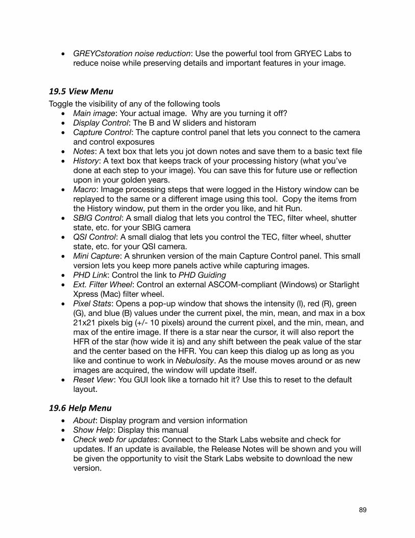
• GREYCstoration noise reduction: Use the powerful tool from GRYEC Labs to reduce noise while preserving details and important features in your image.
19.5 View MenuToggle the visibility of any of the following tools
• Main image: Your actual image. Why are you turning it off?• Display Control: The B and W sliders and historam• Capture Control: The capture control panel that lets you connect to the camera
and control exposures• Notes: A text box that lets you jot down notes and save them to a basic text file• History: A text box that keeps track of your processing history (what you’ve
done at each step to your image). You can save this for future use or reflection upon in your golden years.
• Macro: Image processing steps that were logged in the History window can be replayed to the same or a different image using this tool. Copy the items from the History window, put them in the order you like, and hit Run.
• SBIG Control: A small dialog that lets you control the TEC, filter wheel, shutter state, etc. for your SBIG camera
• QSI Control: A small dialog that lets you control the TEC, filter wheel, shutter state, etc. for your QSI camera.
• Mini Capture: A shrunken version of the main Capture Control panel. This small version lets you keep more panels active while capturing images.
• PHD Link: Control the link to PHD Guiding• Ext. Filter Wheel: Control an external ASCOM-compliant (Windows) or Starlight
Xpress (Mac) filter wheel.• Pixel Stats: Opens a pop-up window that shows the intensity (I), red (R), green
(G), and blue (B) values under the current pixel, the min, mean, and max in a box 21x21 pixels big (+/- 10 pixels) around the current pixel, and the min, mean, and max of the entire image. If there is a star near the cursor, it will also report the HFR of the star (how wide it is) and any shift between the peak value of the star and the center based on the HFR. You can keep this dialog up as long as you like and continue to work in Nebulosity. As the mouse moves around or as new images are acquired, the window will update itself.
• Reset View: You GUI look like a tornado hit it? Use this to reset to the default layout.
19.6 Help Menu• About: Display program and version information • Show Help: Display this manual • Check web for updates: Connect to the Stark Labs website and check for
updates. If an update is available, the Release Notes will be shown and you will be given the opportunity to visit the Stark Labs website to download the new version.
89
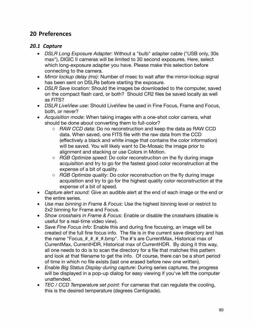
20 Preferences
20.1 Capture• DSLR Long Exposure Adapter: Without a "bulb" adapter cable ("USB only, 30s
max"), DIGIC II cameras will be limited to 30 second exposures. Here, select which long-exposure adapter you have. Please make this selection before connecting to the camera.
• Mirror lockup delay (ms): Number of msec to wait after the mirror-lockup signal has been sent on DSLRs before starting the exposure.
• DSLR Save location: Should the images be downloaded to the computer, saved on the compact flash card, or both? Should CR2 files be saved locally as well as FITS?
• DSLR LiveView use: Should LiveView be used in Fine Focus, Frame and Focus, both, or never?
• Acquisition mode: When taking images with a one-shot color camera, what should be done about converting them to full-color?
o RAW CCD data: Do no reconstruction and keep the data as RAW CCD data. When saved, one FITS file with the raw data from the CCD (effectively a black and white image that contains the color information) will be saved. You will likely want to De-Mosaic the image prior to alignment and stacking or use Colors in Motion.
o RGB Optimize speed: Do color reconstruction on the fly during image acquisition and try to go for the fastest good color reconstruction at the expense of a bit of quality.
o RGB Optimize quality: Do color reconstruction on the fly during image acquisition and try to go for the highest quality color reconstruction at the expense of a bit of speed.
• Capture alert sound: Give an audible alert at the end of each image or the end or the entire series.
• Use max binning in Frame & Focus: Use the highest binning level or restrict to 2x2 binning for Frame and Focus.
• Show crosshairs in Frame & Focus: Enable or disable the crosshairs (disable is useful for a real-time video view).
• Save Fine Focus info: Enable this and during fine focusing, an image will be created of the full fine focus info. The file is in the current save directory and has the name "Focus_#_#_#_#.bmp". The #'s are CurrentMax, Historical max of CurrentMax, CurrentHDR, Historical max of CurrentHDR. By doing it this way, all one needs to do is to scan the directory for a file that matches this pattern and look at that filename to get the info. Of course, there can be a short period of time in which no file exists (last one erased before new one written).
• Enable Big Status Display during capture: During series captures, the progress will be displayed in a pop-up dialog for easy viewing if you've left the computer unattended.
• TEC / CCD Temperature set point: For cameras that can regulate the cooling, this is the desired temperature (degrees Centigrade).
90
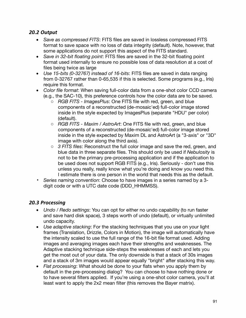
20.2 Output• Save as compressed FITS: FITS files are saved in lossless compressed FITS
format to save space with no loss of data integrity (default). Note, however, that some applications do not support this aspect of the FITS standard.
• Save in 32-bit floating point: FITS files are saved in the 32-bit floating point format used internally to ensure no possible loss of data resolution at a cost of files being twice as large
• Use 15-bits (0-32767) instead of 16-bits: FITS files are saved in data ranging from 0-32767 rather than 0-65,535 if this is selected. Some programs (e.g., Iris) require this format.
• Color file format: When saving full-color data from a one-shot color CCD camera (e.g., the SAC-10), this preference controls how the color data are to be saved.
o RGB FITS - ImagesPlus: One FITS file with red, green, and blue components of a reconstructed (de-mosaic'ed) full-color image stored inside in the style expected by ImagesPlus (separate "HDU" per color) (default).
o RGB FITS - Maxim / AstroArt: One FITS file with red, green, and blue components of a reconstructed (de-mosaic'ed) full-color image stored inside in the style expected by Maxim DL and AstroArt (a "3-axis" or "3D" image with color along the third axis).
o 3 FITS files: Reconstruct the full color image and save the red, green, and blue data in three separate files. This should only be used if Nebulosity is not to be the primary pre-processing application and if the application to be used does not support RGB FITS (e.g., Iris). Seriously - don’t use this unless you really, really know what you’re doing and know you need this. I estimate there is one person in the world that needs this as the default.
• Series naming convention: Choose to have images in a series named by a 3-digit code or with a UTC date code (DDD_HHMMSS).
20.3 Processing• Undo / Redo settings: You can opt for either no undo capability (to run faster
and save hard disk space), 3 steps worth of undo (default), or virtually unlimited undo capacity.
• Use adaptive stacking: For the stacking techniques that you use on your light frames (Translation, Drizzle, Colors in Motion), the image will automatically have the intensity scaled to use the full range of the 16-bit file format used. Adding images and averaging images each have their strengths and weaknesses. The Adaptive stacking technique side-steps the weaknesses of each and lets you get the most out of your data. The only downside is that a stack of 30s images and a stack of 3m images would appear equally "bright" after stacking this way.
• Flat processing: What should be done to your flats when you apply them by default in the pre-processing dialog? You can choose to have nothing done or to have several filters applied. If you’re using a one-shot color camera, you’ll at least want to apply the 2x2 mean filter (this removes the Bayer matrix).
91
• Demosaic (debayer) method: What algorithm should be used for converting one-shot color images to color? VNG (Variable Number of Gradients by Ting Chen) is the default and an excellent choice. PPG (Patterned Pixel Grouping by Alain Desboilles) and AHD (Adaptive Homogeneity-Directed by Keigo Hirakawa, Thomas Parks, and Paul Lee) are also popular advanced debayers. Bilinear is quite fast if a bit soft. Color binning will reduce your image size by a factor of 2 but does no interpolation.
• Manually override color reconstruction: Typically, Nebulosity will attempt to determine what kind of camera a one-shot color file comes from and set the various demosaic options automatically. At times, you may wish to override this automatic behavior and specify offsets, array types, color mixing, etc. manually. Enabling this preference will bring the manual color reconstruction dialog up each time so that you can override any automatic behavior.
• DSLR White Balance / IR filter: Ideally, the pixels are white balanced prior to actually implementing the demosaic of a RAW image. For most cameras, this white balance is known a priori, but DSLRs can be stock or modified. Choose the setting here that best corresponds to your camera setup. Note, that at times, if there are severely saturated areas, this may lead to a pink area in the saturated zones. If this occurs, the Straight Color Scale option can be used.
20.4 ColorsIf you want to customize the interface’s coloring, you’ve got a few options here. Have fun!
20.5 Misc• Display orientation: Should Nebulosity flip or rotate the display?• Clock / TEC display: In the control panel, Nebulosity can display a small clock
that will show the current time in a range of time formats or show the CCD's current temperature. The time formats all use your computer's internal clock as the starting point and convert that into other times. Note that local sidereal time and Polaris RA depend on Nebulosity knowing your longitude.
o No clock: Hide the clock o Local time: The current local time o UT/GMT time: The current Universal Time (or Greenwich Mean Time) o GMT Sidereal: GMST or Greenwich Mean Sidereal Time o Local sidereal: The current local sidereal time (useful in finding objects
with setting circles) o Polaris RA: Polaris' current right ascension (useful in using polar
alignment scopes) o CCD Temperature: Current temperature of the CCD in centigrade.
• Longitude: Local sidereal and Polaris RA require knowing your current longitude. Enter it in decimal notation (e.g., -77.1 not H:M:S) with west (e.g., USA locations) being negative.
92
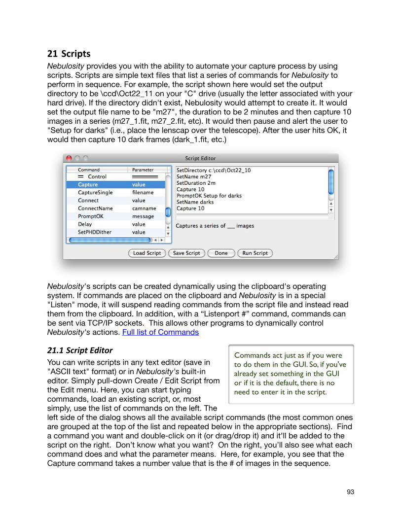
21 ScriptsNebulosity provides you with the ability to automate your capture process by using scripts. Scripts are simple text files that list a series of commands for Nebulosity to perform in sequence. For example, the script shown here would set the output directory to be \ccd\Oct22_11 on your "C" drive (usually the letter associated with your hard drive). If the directory didn't exist, Nebulosity would attempt to create it. It would set the output file name to be "m27", the duration to be 2 minutes and then capture 10 images in a series (m27_1.fit, m27_2.fit, etc). It would then pause and alert the user to "Setup for darks" (i.e., place the lenscap over the telescope). After the user hits OK, it would then capture 10 dark frames (dark_1.fit, etc.)
Nebulosity's scripts can be created dynamically using the clipboard's operating system. If commands are placed on the clipboard and Nebulosity is in a special "Listen" mode, it will suspend reading commands from the script file and instead read them from the clipboard. In addition, with a “Listenport #” command, commands can be sent via TCP/IP sockets. This allows other programs to dynamically control Nebulosity's actions. Full list of Commands
21.1 Script EditorYou can write scripts in any text editor (save in "ASCII text" format) or in Nebulosity's built-in editor. Simply pull-down Create / Edit Script from the Edit menu. Here, you can start typing commands, load an existing script, or, most simply, use the list of commands on the left. The left side of the dialog shows all the available script commands (the most common ones are grouped at the top of the list and repeated below in the appropriate sections). Find a command you want and double-click on it (or drag/drop it) and it’ll be added to the script on the right. Don’t know what you want? On the right, you’ll also see what each command does and what the parameter means. Here, for example, you see that the Capture command takes a number value that is the # of images in the sequence.
Commands act just as if you were to do them in the GUI. So, if you've already set something in the GUI or if it is the default, there is no need to enter it in the script.
93
When done, you'll likely want to save your script (Save button) and then press Done. When you're ready to execute the script, either press Run Script while the Script Editor is open or simply pull down Run Script from the Edit menu. Nebulosity will then first verify that it's a valid script. Then, it will go through line by line, executing each command until it reaches the end of the file. As it does so, the Status bar will keep you apprised of what Nebulosity is currently doing. Pressing the Abort button will cancel the script at any time.
One thing of note - when you’re specifying times, the units are seconds (in Nebulosity 1 and 2 times were all in milliseconds). You can use fractions if you like (e.g., 10.5 would be ten and a half seconds and 0.001 would be one millisecond). You can also put an “m” suffix on the number to indicate minutes. So, if you wanted a minute and a half (90 seconds) exposure you could use “90”, “90.0”, or “1.5m”.
21.2 Full Command ListThe following is the list of commands recognized by Nebulosity. They are presented here capitalized to help show you the meaning of the command, but Nebulosity ignores the case of all commands. So, "SetName" is the same as "setname" and "SeTNAme".
Each command must be placed on a separate line and each line must have a command and a parameter with at least one space between the command and the parameter. When the list shows the parameter to be N, it means a number should be provided as the parameter. When the list shows the parameter to be S, it means a string (aka text) should be provided as the parameter.
21.2.1 Capture Setup CommandsThese commands mirror the controls present in the Control Panel and several of the settings available in the Preferences menu.
• SetName S - Sets the base filename to be S • SetDirectory S - Sets the capture directory to be S • SetDuration N - Sets the exposure duration to N seconds (fractions allowed -
use “m” as a suffix to denote minutes) • SetTimelapse N - Sets the time lapse to be N seconds (fractions allowed - use
“m” as a suffix to denote minutes) • SetBinning N – Sets the bin mode. 0:No binning, 1 or 2:2x2, 3:3x3, 4:4x4
Script files can contain extra spaces or blank lines if you want to make them look cleaner when writing them. Nebulosity will simply skip any extra spaces or lines it finds. In addition, if you start a line with the “#” symbol, the line will be ignored. This is a useful way to put comments in your scripts.
You can execute scripts at startup by passing the script name as a command-line argument. For example "nebulosity script.neb" will automatically execute script.neb
94

• SetShutter N – Sets the shutter state. 0:Open (light frame), 1:Closed (dark frame)
• SetFilter N – Selects filter #N from your camera’s filter wheel if connected (1-indexed)
• SetExtFilter N – Selects filter #N on the external filter wheel if connected (1-indexed)
• SetGain N - Sets the camera gain to be N • SetOffset N - Sets the camera offset to be N • SetColorFormat N - Sets the color file format used when (and if) full-color
images are written. 0: RGB FITS in ImagesPlus format. 1: RGB FITS in Maxim / AstroArt format. 2: 3 separate FITS files.
• SetAcqMode N - Sets the color acquisition mode. 0: RAW or BW images. 1: RGB Optimize speed. 2: RGB Optimize quality.
21.2.2 Control CommandsThese commands control the capturing process itself and let you interact with the user.
• Capture N - Captures a series with N images according to the current settings. • CaptureSingle S - This (e.g., “CaptureSingle foo”) will capture a single frame
and save it with the given name (e.g. “foo.fit”) even if it already exists. The file will be in the current save directory. In addition, if the filename specified is "metric" (or "metric.fit"), it will run the whole-image HFR routine used in quality grading and the file will be "metric_###.fit". The ### is 100x the HFR. Note, since Nebulosity doesn't know when this file has been used and when you're done with it, it will only erase / write a new one if you run CaptureSingle again. If you quit Nebulosity though, this file will still linger in the directory.
• Connect N - Connect to camera N where N is where you would find the camera in the pull-down list in Nebulosity's main window (0=indexed). So, “No camera” (aka disconnect) is “Connect 0”.
• ConnectName S - Connect to camera named S, where S is the name as-listed in the pull-down list in the main window. For example, “Connect Meade DSI”
• PromptOK S - Displays S on the screen and prompts the user to hit OK or Cancel. If OK is hit, the script continues. If Cancel is hit, the script is stopped.
• Delay N - Pause execution for N seconds (fractions allowed - use “m” as a suffix to denote minutes)
• SetPHDDither N - Sets the dither level in the link to PHD guiding (0=none, 1=small, ... 5=extreme)
• SetBLevel N and SetWLevel N - Sets the B and W slider levels to N. If N = -1, auto-scaling is turned on.
• Listen N - Enable (1) or disable (0) listening to commands from the clipboard. Each command on the clipboard must start with "/NEB". For example, "/NEB Listen 0" on the clipboard will return processing to the script file.
• Listenport N - Enable (port number) or disable (0) listening to commands via sockets. For example, you might have a script with one line saying: Listenport 4301 and when run, Nebulosity would begin waiting for a connection on port
95
4301. o Nebulosity first waits for the connection to be formed (if you wish to
bail, the Capture Abort will break out) and after that, it enters into a loop. It will wait for any data to come in using "blocking sockets". There is a timeout of 1s per read though, giving you the ability to break out. Many commands can be sent at once and if there are commands still to be processed, Nebulosity will do them without waiting (currently, a 2kb buffer is used for each read). Thus, it's not like you can only do one command per second. You can only abort once a second.
o To leave the mode and return control to Nebulosity itself either a) break the connection (Nebulosity will pop up a "connection lost" dialog) or b) send the command "Listenport 0".
o During all this, a small dialog will pop up that will show what Nebulosity is getting over the port, the status of the connection, etc. -- all useful info for debugging. At the moment, said dialog is not functioning on the Mac but you will see things flash by on the status bar.
• Exit N - Wait N milliseconds and then exit the program
21.2.3 Advanced Camera Control CommandsThese commands have the same function as the Advanced camera dialog box, allowing you to override the current settings shown in the dialog. If the camera is not capable of the command given in the script, the command is ignored.
• SetAmpControl N - 1: Amplifier control is enabled and the CCD amp is off during exposures. 0: Amplifier control is disabled and the CCD amp is on during exposures.
• SetHighSpeed N - 1: Enable high speed readout mode. 0: Disable high speed readout mode.
• SetOversample N - 1: Enable CCD oversampling. 0: Disable CCD oversampling.
• SetDoubleRead N - 1: Enable double-read mode. 0: Disable double-read mode
96