variable speed drives safety functions · pdf filevariable speed drives safety functions...
TRANSCRIPT

S1A
45
60
6.0
3
www.schneider-electric.com
Altivar 32Variable Speed Drives Safety Functions Manual
08/2014

2 S1A45606 08/2014
The information provided in this documentation contains general descriptions and/or technical character-
istics of the performance of the products contained herein. This documentation is not intended as a
substitute for and is not to be used for determining suitability or reliability of these products for specific user
applications. It is the duty of any such user or integrator to perform the appropriate and complete risk
analysis, evaluation and testing of the products with respect to the relevant specific application or use
thereof. Neither Schneider Electric nor any of its affiliates or subsidiaries shall be responsible or liable for
misuse of the information contained herein. If you have any suggestions for improvements or amendments
or have found errors in this publication, please notify us.
No part of this document may be reproduced in any form or by any means, electronic or mechanical,
including photocopying, without express written permission of Schneider Electric.
All pertinent state, regional, and local safety regulations must be observed when installing and using this
product. For reasons of safety and to help ensure compliance with documented system data, only the
manufacturer should perform repairs to components.
When devices are used for applications with technical safety requirements, the relevant instructions must
be followed.
Failure to use Schneider Electric software or approved software with our hardware products may result in
injury, harm, or improper operating results.
Failure to observe this information can result in injury or equipment damage.
© 2013 Schneider Electric. All rights reserved.

S1A45606 08/2014 3
Table of Contents
Safety Information . . . . . . . . . . . . . . . . . . . . . . . . . . . . . . . . . . . . . . . . . . . 5
About the Book. . . . . . . . . . . . . . . . . . . . . . . . . . . . . . . . . . . . . . . . . . . . . . 7
Chapter 1 Generalities . . . . . . . . . . . . . . . . . . . . . . . . . . . . . . . . . . . . . . . . . . . . . . . . . 11Introduction . . . . . . . . . . . . . . . . . . . . . . . . . . . . . . . . . . . . . . . . . . . . . . . . . . . . . . . . . . . . . . 12Standards and Terminology . . . . . . . . . . . . . . . . . . . . . . . . . . . . . . . . . . . . . . . . . . . . . . . . . 13Basics . . . . . . . . . . . . . . . . . . . . . . . . . . . . . . . . . . . . . . . . . . . . . . . . . . . . . . . . . . . . . . . . . . 14
Chapter 2 Description . . . . . . . . . . . . . . . . . . . . . . . . . . . . . . . . . . . . . . . . . . . . . . . . . 17Safety Function STO (Safe Torque Off) . . . . . . . . . . . . . . . . . . . . . . . . . . . . . . . . . . . . . . . . 18Safety Function SS1 (Safe Stop 1) . . . . . . . . . . . . . . . . . . . . . . . . . . . . . . . . . . . . . . . . . . . . 20Safety Function SLS (Safely-Limited Speed) . . . . . . . . . . . . . . . . . . . . . . . . . . . . . . . . . . . . 22
Chapter 3 Calculation of Safety Related Parameters . . . . . . . . . . . . . . . . . . . . . . . . 29SLS Type 1 . . . . . . . . . . . . . . . . . . . . . . . . . . . . . . . . . . . . . . . . . . . . . . . . . . . . . . . . . . . . . . 30SLS Type 2, Type 3, Type 4, Type 5, and Type 6. . . . . . . . . . . . . . . . . . . . . . . . . . . . . . . . . 32SS1 . . . . . . . . . . . . . . . . . . . . . . . . . . . . . . . . . . . . . . . . . . . . . . . . . . . . . . . . . . . . . . . . . . . . 35
Chapter 4 Behavior of Safety Functions . . . . . . . . . . . . . . . . . . . . . . . . . . . . . . . . . . 37Limitations . . . . . . . . . . . . . . . . . . . . . . . . . . . . . . . . . . . . . . . . . . . . . . . . . . . . . . . . . . . . . . . 38Detected Fault Inhibition . . . . . . . . . . . . . . . . . . . . . . . . . . . . . . . . . . . . . . . . . . . . . . . . . . . . 39Priority Between Safety Functions. . . . . . . . . . . . . . . . . . . . . . . . . . . . . . . . . . . . . . . . . . . . . 40Factory Settings. . . . . . . . . . . . . . . . . . . . . . . . . . . . . . . . . . . . . . . . . . . . . . . . . . . . . . . . . . . 41Configuration Download . . . . . . . . . . . . . . . . . . . . . . . . . . . . . . . . . . . . . . . . . . . . . . . . . . . . 42Priority Between Safety Functions and No Safety-Related Functions. . . . . . . . . . . . . . . . . . 43
Chapter 5 Safety Functions Visualization by HMI. . . . . . . . . . . . . . . . . . . . . . . . . . . 47Status of Safety Functions. . . . . . . . . . . . . . . . . . . . . . . . . . . . . . . . . . . . . . . . . . . . . . . . . . . 48Dedicated HMI. . . . . . . . . . . . . . . . . . . . . . . . . . . . . . . . . . . . . . . . . . . . . . . . . . . . . . . . . . . . 49Error Code Description . . . . . . . . . . . . . . . . . . . . . . . . . . . . . . . . . . . . . . . . . . . . . . . . . . . . . 50
Chapter 6 Technical Data . . . . . . . . . . . . . . . . . . . . . . . . . . . . . . . . . . . . . . . . . . . . . . 57Electrical Data . . . . . . . . . . . . . . . . . . . . . . . . . . . . . . . . . . . . . . . . . . . . . . . . . . . . . . . . . . . . 58Getting and Operating the Safety Function . . . . . . . . . . . . . . . . . . . . . . . . . . . . . . . . . . . . . . 59Safety Function Capability . . . . . . . . . . . . . . . . . . . . . . . . . . . . . . . . . . . . . . . . . . . . . . . . . . . 60Debounce Time and Response Time . . . . . . . . . . . . . . . . . . . . . . . . . . . . . . . . . . . . . . . . . . 62
Chapter 7 Certified Architectures. . . . . . . . . . . . . . . . . . . . . . . . . . . . . . . . . . . . . . . . 63Introduction . . . . . . . . . . . . . . . . . . . . . . . . . . . . . . . . . . . . . . . . . . . . . . . . . . . . . . . . . . . . . . 64Multi-drive with the Safety Module Type Preventa XPS AF - Case 1 . . . . . . . . . . . . . . . . . . 65Multi-drive with the Safety Module Type Preventa XPS AF - Case 2 . . . . . . . . . . . . . . . . . . 66Multi-drive Without the Safety Module. . . . . . . . . . . . . . . . . . . . . . . . . . . . . . . . . . . . . . . . . . 67Single Drive with the Safety Module Type Preventa XPS AV - Case 1. . . . . . . . . . . . . . . . . 68Single Drive with the Safety Module Type Preventa XPS AV - Case 2. . . . . . . . . . . . . . . . . 69Single Drive with the Safety Module Type Preventa XPS AF - Case 1 . . . . . . . . . . . . . . . . . 70Single Drive with the Safety Module Type Preventa XPS AF - Case 2 . . . . . . . . . . . . . . . . . 71Single Drive According to IEC 61508 and IEC 60204-1 - Case 1 . . . . . . . . . . . . . . . . . . . . . 72Single Drive According to IEC 61508 and IEC 60204-1 - Case 2 . . . . . . . . . . . . . . . . . . . . . 73
Chapter 8 Commissioning. . . . . . . . . . . . . . . . . . . . . . . . . . . . . . . . . . . . . . . . . . . . . . 75Safety Functions Tab. . . . . . . . . . . . . . . . . . . . . . . . . . . . . . . . . . . . . . . . . . . . . . . . . . . . . . . 76Configure Safety Functions Panel . . . . . . . . . . . . . . . . . . . . . . . . . . . . . . . . . . . . . . . . . . . . . 77Visualization and Status of Safety Functions . . . . . . . . . . . . . . . . . . . . . . . . . . . . . . . . . . . . 81Copying Safety Related Configuration from Device to PC and from PC to Device . . . . . . . . 82Machine Signature. . . . . . . . . . . . . . . . . . . . . . . . . . . . . . . . . . . . . . . . . . . . . . . . . . . . . . . . . 85
Chapter 9 Services and Maintenance. . . . . . . . . . . . . . . . . . . . . . . . . . . . . . . . . . . . . 89Maintenance . . . . . . . . . . . . . . . . . . . . . . . . . . . . . . . . . . . . . . . . . . . . . . . . . . . . . . . . . . . . . 90Power and MCU Replacement . . . . . . . . . . . . . . . . . . . . . . . . . . . . . . . . . . . . . . . . . . . . . . . 91Changing Machine Equipment . . . . . . . . . . . . . . . . . . . . . . . . . . . . . . . . . . . . . . . . . . . . . . . 92

4 S1A45606 08/2014
S1A45606 08/2014 5
Safety Information
Important Information
NOTICE
Read these instructions carefully, and look at the equipment to become familiar with the device before
trying to install, operate, or maintain it. The following special messages may appear throughout this
documentation or on the equipment to warn of potential hazards or to call attention to information that
clarifies or simplifies a procedure.
PLEASE NOTE
Electrical equipment should be installed, operated, serviced, and maintained only by qualified personnel.
No responsibility is assumed by Schneider Electric for any consequences arising out of the use of this
material.
A qualified person is one who has skills and knowledge related to the construction and operation of
electrical equipment and its installation, and has received safety training to recognize and avoid the
hazards involved.

6 S1A45606 08/2014

S1A45606 08/2014 7
About the Book
At a Glance
Document Scope
The purpose of this document is to provide information about safety functions incorporated in Altivar 32.
These functions allow you to develop applications oriented in the protection of man and machine.
FDT/DTM (field device tool / device type manager) is a new technology chosen by several companies in
automation.
To install the Altivar 32 DTM, you can download and install our FDT: SoMove lite on www.schneider-
electric.com. It is including the Altivar 32 DTM.
The content of this manual is also accessible through the ATV32 DTM online help.
Validity Note
This documentation is valid for the Altivar 32 drive.
The technical characteristics of the devices described in this document also appear online. To access this
information online:
The characteristics that are presented in this manual should be the same as those characteristics that
appear online. In line with our policy of constant improvement, we may revise content over time to improve
clarity and accuracy. If you see a difference between the manual and online information, use the online
information as your reference.
Related Documents
Step Action
1 Go to the Schneider Electric home page www.schneider-electric.com.
2 In the Search box type the reference of a product or the name of a product range.
Do not include blank spaces in the model number/product range.
To get information on grouping similar modules, use asterisks (*).
3 If you entered a reference, go to the Product Datasheets search results and click on the reference that
interests you.
If you entered the name of a product range, go to the Product Ranges search results and click on the product
range that interests you.
4 If more than one reference appears in the Products search results, click on the reference that interests you.
5 Depending on the size of your screen, you may need to scroll down to see the data sheet.
6 To save or print a data sheet as a .pdf file, click Download XXX product datasheet.
Title of Documentation Reference Number
ATV32 Quick Start Guide S1A41715
ATV32 Quick Start Annex S1B39941
ATV32 Installation Manual S1A28686
ATV32 Programming Manual S1A28692
ATV32 Atex Manual S1A45605
ATV32 Safety Integrated Functions Manual S1A45606
ATV32 Modbus Manual S1A28698
ATV32 CANopen Manual S1A28699
ATV32 PROFIBUS DP Manual S1A28700
ATV32 Modbus TCP - EtherNet/IP Manual S1A28701
ATV32 DeviceNet Manual S1A28702
ATV32 EtherCAT Manual S1A28703
ATV32 PROFINET Manual HRB25668
ATV32 Communication Parameters Manual S1A44568

8 S1A45606 08/2014
You can download these technical publications and other technical information from our website at
www.schneider-electric.com.
Product Related Information
The information provided in this manual supplements the product manuals.
Carefully read the product manuals before using the product.
Read and understand these instructions before performing any procedure with this drive.
BMP Synchronous Motor Manual 0198441113981
ATV32 Certificates, See www.schneider-electric.com NA
Title of Documentation Reference Number
DANGERHAZARD OF ELECTRIC SHOCK, EXPLOSION, OR ARC FLASH
Only appropriately trained persons who are familiar with and understand the contents of this manual
and all other pertinent product documentation and who have received safety training to recognize and
avoid hazards involved are authorized to work on and with this drive system. Installation, adjustment,
repair, and maintenance must be performed by qualified personnel.
The system integrator is responsible for compliance with all local and national electrical code
requirements as well as all other applicable regulations with respect to grounding of all equipment.
Many components of the product, including the printed circuit boards, operate with mains voltage. Do
not touch. Use only electrically insulated tools.
Do not touch unshielded components or terminals with voltage present.
Motors can generate voltage when the shaft is rotated. Before performing any type of work on the drive
system, block the motor shaft to prevent rotation.
AC voltage can couple voltage to unused conductors in the motor cable. Insulate both ends of unused
conductors of the motor cable.
Do not short across the DC bus terminals or the DC bus capacitors or the braking resistor terminals.
Before performing work on the drive system:
Disconnect all power, including external control power that may be present.
Place a "Do Not Turn On" label on all power switches.
Lock all power switches in the open position.
Wait 15minutes to allow the DC bus capacitors to discharge. The DC bus LED is not an indicator
of the absence of DC bus voltage that can exceed 800 Vdc.
Measure the voltage on the DC bus between the DC bus terminals using a properly rated voltmeter
to verify that the voltage is < 42Vdc.
If the DC bus capacitors do not discharge properly, contact your local Schneider Electric
representative.
Install and close all covers before applying voltage.
Failure to follow these instructions will result in death or serious injury.
DANGERUNINTENDED EQUIPMENT OPERATION
Read and understand this manual before installing or operating the drive.
Any changes made to the parameter settings must be performed by qualified personnel.
Failure to follow these instructions will result in death or serious injury.
WARNINGDAMAGED DRIVE EQUIPMENT
Do not operate or install any drive or drive accessory that appears damaged.
Failure to follow these instructions can result in death, serious injury, or equipment damage.
S1A45606 08/2014 9
1. For USA: Additional information, refer to NEMA ICS 1.1 (latest edition), “Safety guidelines for the
application, installation, and maintenance of solid-State control” and to NEMA ICS 7.1 (latest edition),
“Safety standards for construction and guide for selection, installation, and operation of adjustable
speed drive systems.”
WARNINGLOSS OF CONTROL
The designer of any control scheme must consider the potential failure modes of control paths and,
for critical control functions, provide a means to achieve a safe state during and after a path failure.
Examples of critical control functions are emergency stop, overtravel stop, power outage, and restart.
Separate or redundant control paths must be provided for critical control functions.System control
paths may include communication links. Consideration must be given to the implications of
unanticipated transmission delays or failures of the link.
System control paths may include communication links. Consideration must be given to the
implications of unanticipated transmission delays or failures of the link.
Observe all accident prevention regulations and local safety guidelines.(1)
Each implementation of the product must be individually and thoroughly tested for proper operation
before being placed into service.
Failure to follow these instructions can result in death, serious injury, or equipment damage.
CAUTIONINCOMPATIBLE LINE VOLTAGE
Before turning on and configuring the drive, ensure that the line voltage is compatible with the supply
voltage range shown on the drive nameplate. The drive may be damaged if the line voltage is not
compatible.
Failure to follow these instructions can result in injury or equipment damage.
NOTICE
RISK OF DERATED PERFORMANCE DUE TO CAPACITOR AGING
The product capacitor performances after a long time storage above 2 years can be degraded. In that
case, before using the product, apply the following procedure:
Use a variable AC supply connected between L1 and L2 (even for ATVpppppN4 references).
Increase AC supply voltage to have:
80% of rated voltage during 30 min
100% of rated voltage for another 30 min
Failure to follow these instructions can result in equipment damage.

10 S1A45606 08/2014
Qualification of personnel
Only appropriately trained persons who are familiar with and understand the contents of this manual and
all other pertinent product documentation are authorized to work on and with this product. In addition, these
persons must have received safety training to recognize and avoid hazards involved. These persons must
have sufficient technical training, knowledge and experience and be able to foresee and detect potential
hazards that may be caused by using the product, by changing the settings and by the mechanical,
electrical and electronic equipment of the entire system in which the product is used.
All persons working on and with the product must be fully familiar with all applicable standards, directives,
and accident prevention regulations when performing such work.
Intended use
The functions described in this manual are only intended for use with the basic product; you must read and
understand the appropriate product manual.The product may only be used in compliance with all
applicable safety regulations and directives, the specified requirements and the technical data.Prior to
using the product, you must perform a risk assessment in view of the planned application. Based on the
results, the appropriate safety measures must be implemented.Since the product is used as a component
in an entire system, you must ensure the safety of persons by means of the design of this entire system
(for example, machine design).
Operate the product only with the specified cables and accessories. Use only genuine accessories and
spare parts.Any use other than the use explicitly permitted is prohibited and can result in hazards.Electrical
equipment should be installed, operated, serviced, and maintained only by qualified personnel.The product
must NEVER be operated in explosive atmospheres (hazardous locations, Ex areas).
S1A45606 08/2014 11
Generalities
Chapter 1Generalities
What Is in This Chapter?
This chapter contains the following topics:
Topic Page
Introduction 12
Standards and Terminology 13
Basics 14
12 S1A45606 08/2014
Introduction
Overview
The safety functions incorporated in Altivar 32 are intended to maintain the safe condition of the installation
or prevent hazardous conditions arising at the installation. In some cases, further safety-related systems
external to the drive (for example a mechanical brake) may be necessary to maintain the safe condition
when electrical power is removed.
The safety functions are configured with SoMove software.
Integrated safety functions provide the following benefits:
Additional standards-compliant safety functions
No need for external safety-related devices
Reduced wiring effort and space requirements
Reduced costs
The Altivar 32 drives are compliant with the requirements of the standards in terms of implementation of
safety functions.
Safety Functions as Defined by IEC 61800-5-2
Definitions
Notation
The graphic display terminal (to be ordered separately - reference VW3A1101) menus are shown in square
brackets.
The integrated 7-segment display terminal menus are shown in round brackets.
Parameter names are displayed on the graphic display terminal in square brackets.
Parameter codes are displayed on the integrated 7-segment display terminal in round brackets.
Acronym Description
STO Safe Torque Off
No power that could cause torque or force is supplied to the motor.
SLS Safely-Limited Speed
The SLS function prevents the motor from exceeding the specified speed limit. If the motor speed exceeds
the specified speed limit value, safety function STO is triggered.
SS1 Safe Stop 1
initiates and monitors the motor deceleration rate within set limits to stop the motor
initiates the Safe Operating Stop function when the motor speed is below the specified limit
DANGERELECTRIC SHOCK CAUSED BY INCORRECT USE
The safety function STO ([Safe Torque Off]) does not cause electric isolation. The DC bus voltage is
still present.
Turn off the main voltage using an appropriate switch to achieve a voltage-free condition.
Failure to follow these instructions will result in death or serious injury.
S1A45606 08/2014 13
Standards and Terminology
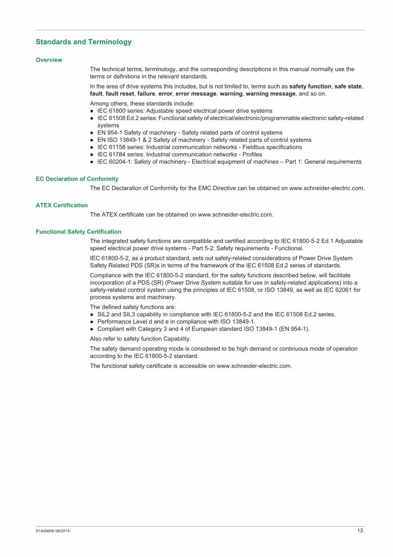
Overview
The technical terms, terminology, and the corresponding descriptions in this manual normally use the
terms or definitions in the relevant standards.
In the area of drive systems this includes, but is not limited to, terms such as safety function, safe state,
fault, fault reset, failure, error, error message, warning, warning message, and so on.
Among others, these standards include:
IEC 61800 series: Adjustable speed electrical power drive systems
IEC 61508 Ed.2 series: Functional safety of electrical/electronic/programmable electronic safety-related
systems
EN 954-1 Safety of machinery - Safety related parts of control systems
EN ISO 13849-1 & 2 Safety of machinery - Safety related parts of control systems
IEC 61158 series: Industrial communication networks - Fieldbus specifications
IEC 61784 series: Industrial communication networks - Profiles
IEC 60204-1: Safety of machinery - Electrical equipment of machines – Part 1: General requirements
EC Declaration of Conformity
The EC Declaration of Conformity for the EMC Directive can be obtained on www.schneider-electric.com.
ATEX Certification
The ATEX certificate can be obtained on www.schneider-electric.com.
Functional Safety Certification
The integrated safety functions are compatible and certified according to IEC 61800-5-2 Ed.1 Adjustable
speed electrical power drive systems - Part 5-2: Safety requirements - Functional.
IEC 61800-5-2, as a product standard, sets out safety-related considerations of Power Drive System
Safety Related PDS (SR)s in terms of the framework of the IEC 61508 Ed.2 series of standards.
Compliance with the IEC 61800-5-2 standard, for the safety functions described below, will facilitate
incorporation of a PDS (SR) (Power Drive System suitable for use in safety-related applications) into a
safety-related control system using the principles of IEC 61508, or ISO 13849, as well as IEC 62061 for
process systems and machinery.
The defined safety functions are:
SIL2 and SIL3 capability in compliance with IEC 61800-5-2 and the IEC 61508 Ed.2 series.
Performance Level d and e in compliance with ISO 13849-1.
Compliant with Category 3 and 4 of European standard ISO 13849-1 (EN 954-1).
Also refer to safety function Capability.
The safety demand operating mode is considered to be high demand or continuous mode of operation
according to the IEC 61800-5-2 standard.
The functional safety certificate is accessible on www.schneider-electric.com.
14 S1A45606 08/2014
Basics
Functional Safety
Automation and safety engineering are two areas that were completely separate in the past but have
recently become more and more integrated.
The engineering and installation of complex automation solutions are greatly simplified by integrated safety
functions.
Usually, the safety engineering requirements depend on the application.
The level of requirements results from the risk and the hazard potential arising from the specific application.
IEC 61508 Standard
The standard IEC 61508 Functional safety of electrical/electronic/programmable electronic safety-related
systems covers the safety-related function.
Instead of a single component, an entire function chain (for example, from a sensor through the logical
processing units to the actuator) is considered as a unit.
This function chain must meet the requirements of the specific safety integrity level as a whole.
Systems and components that can be used in various applications for safety tasks with comparable risk
levels can be developed on this basis.
SIL - Safety Integrity Level
The standard IEC 61508 defines 4 safety integrity levels (SIL) for safety functions.
SIL1 is the lowest level and SIL4 is the highest level.
A hazard and risk analysis serves as a basis for determining the required safety integrity level.
This is used to decide whether the relevant function chain is to be considered as a safety function and
which hazard potential it must cover.
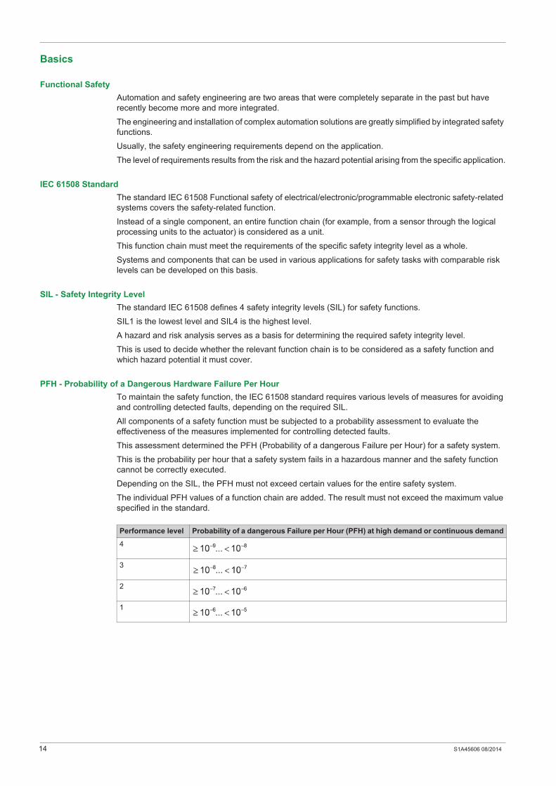
PFH - Probability of a Dangerous Hardware Failure Per Hour
To maintain the safety function, the IEC 61508 standard requires various levels of measures for avoiding
and controlling detected faults, depending on the required SIL.
All components of a safety function must be subjected to a probability assessment to evaluate the
effectiveness of the measures implemented for controlling detected faults.
This assessment determined the PFH (Probability of a dangerous Failure per Hour) for a safety system.
This is the probability per hour that a safety system fails in a hazardous manner and the safety function
cannot be correctly executed.
Depending on the SIL, the PFH must not exceed certain values for the entire safety system.
The individual PFH values of a function chain are added. The result must not exceed the maximum value
specified in the standard.
Performance level Probability of a dangerous Failure per Hour (PFH) at high demand or continuous demand
4
3
2
1

S1A45606 08/2014 15
PL - Performance Level
The standard IEC 13849-1 defines 5 Performance levels (PL) for safety functions.
a is the lowest level and e is the highest level.
Five levels (a, b, c, d, and e) correspond to different values of average probability of dangerous failure per
hour.
HFT - Hardware Fault Tolerance and SFF - Safe Failure Fraction
Depending on the SIL for the safety system, the IEC 61508 standard requires a specific hardware fault
tolerance HFT in connection with a specific proportion of safe failures SFF (Safe Failure Fraction).
The hardware fault tolerance is the ability of a system to execute the required safety function in spite of the
presence of one or more hardware faults.
The SFF of a system is defined as the ratio of the rate of safe failures to the total failure rate of the system.
According to IEC 61508, the maximum achievable SIL of a system is partly determined by the hardware
fault tolerance HFT and the safe failure fraction SFF of the system.
IEC 61508 distinguishes two types of subsystem (type A subsystem, type B subsystem).
These types are specified on the basis of criteria which the standard defines for the safety-relevant
components.
PFD - Probability of Failure on Demand
The standard IEC 61508 defines SIL using requirements grouped into two broad categories: hardware
safety integrity and systematic safety integrity. A device or system must meet the requirements for both
categories to achieve a given SIL.
The SIL requirements for hardware safety integrity are based on a probabilistic analysis of the device. To
achieve a given SIL, the device must meet targets for the maximum probability of dangerous failure and a
minimum Safe Failure Fraction. The concept of ’dangerous failure’ must be rigorously defined for the
system in question, normally in the form of requirement constraints whose integrity is verified throughout
system development. The actual targets required vary depending on the likelihood of a demand, the
complexity of the device(s), and types of redundancy used.
Performance level Probability of a dangerous Hardware Failure per Hour
e
d
c
b
a
SFF HFT type A subsystem HFT type B subsystem
0 1 2 0 1 2
SIL1 SIL2 SIL3 ---- SIL1 SIL2
SIL2 SIL3 SIL4 SIL1 SIL2 SIL3
SIL3 SIL4 SIL4 SIL2 SIL3 SIL4
SIL3 SIL4 SIL4 SIL3 SIL4 SIL4
16 S1A45606 08/2014
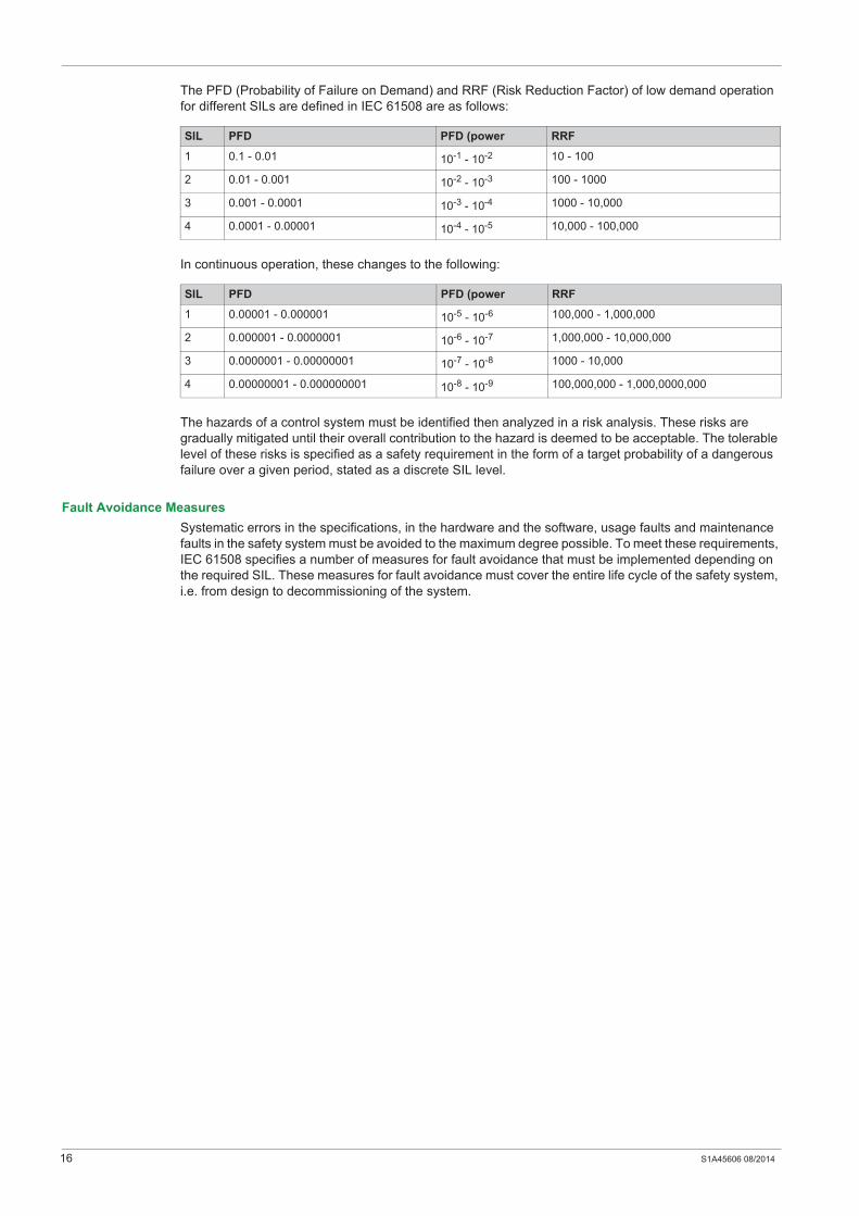
The PFD (Probability of Failure on Demand) and RRF (Risk Reduction Factor) of low demand operation
for different SILs are defined in IEC 61508 are as follows:
In continuous operation, these changes to the following:
The hazards of a control system must be identified then analyzed in a risk analysis. These risks are
gradually mitigated until their overall contribution to the hazard is deemed to be acceptable. The tolerable
level of these risks is specified as a safety requirement in the form of a target probability of a dangerous
failure over a given period, stated as a discrete SIL level.
Fault Avoidance Measures
Systematic errors in the specifications, in the hardware and the software, usage faults and maintenance
faults in the safety system must be avoided to the maximum degree possible. To meet these requirements,
IEC 61508 specifies a number of measures for fault avoidance that must be implemented depending on
the required SIL. These measures for fault avoidance must cover the entire life cycle of the safety system,
i.e. from design to decommissioning of the system.
SIL PFD PFD (power RRF
1 0.1 - 0.01 10-1 - 10-2 10 - 100
2 0.01 - 0.001 10-2 - 10-3 100 - 1000
3 0.001 - 0.0001 10-3 - 10-4 1000 - 10,000
4 0.0001 - 0.00001 10-4 - 10-5 10,000 - 100,000
SIL PFD PFD (power RRF
1 0.00001 - 0.000001 10-5 - 10-6 100,000 - 1,000,000
2 0.000001 - 0.0000001 10-6 - 10-7 1,000,000 - 10,000,000
3 0.0000001 - 0.00000001 10-7 - 10-8 1000 - 10,000
4 0.00000001 - 0.000000001 10-8 - 10-9 100,000,000 - 1,000,0000,000
S1A45606 08/2014 17
Description
Chapter 2Description
What Is in This Chapter?
This chapter contains the following topics:
Topic Page
Safety Function STO (Safe Torque Off) 18
Safety Function SS1 (Safe Stop 1) 20
Safety Function SLS (Safely-Limited Speed) 22

18 S1A45606 08/2014
Safety Function STO (Safe Torque Off)
Overview
This function brings the machine safely into a no-torque state and / or prevents it from starting accidentally.
The safe torque-off (safety function STO) function can be used to effectively implement the prevention of
unexpected start-up functionality, thus making stops safe by preventing the power only to the motor, while
still maintaining power to the main drive control circuits.
The principles and requirements of the prevention of unexpected start-up are described in the standard EN
1037:1995+A1.
The logic input STO is assigned to this safety function and cannot be modified.
If a paired terminal line in 2 channels is required to trigger safety function STO, the function can also be
enabled by the safety-related logic inputs.
The safety function STO is configured with the commissioning software.
The safety function STO status can be displayed using the HMI of the drive or using the commissioning
software.
DANGERELECTRIC SHOCK CAUSED BY INCORRECT USE
The safety function STO (Safe Torque Off) does not cause electric isolation. The DC bus voltage is still
present.
Turn off the mains voltage using an appropriate switch to achieve a voltage-free condition.
Failure to follow these instructions will result in death or serious injury.
S1A45606 08/2014 19
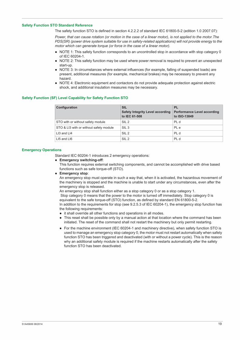
Safety Function STO Standard Reference
The safety function STO is defined in section 4.2.2.2 of standard IEC 61800-5-2 (edition 1.0 2007.07):
Power, that can cause rotation (or motion in the case of a linear motor), is not applied to the motor.The
PDS(SR) (power drive system suitable for use in safety-related applications) will not provide energy to the
motor which can generate torque (or force in the case of a linear motor).
NOTE 1: This safety function corresponds to an uncontrolled stop in accordance with stop category 0
of IEC 60204-1.
NOTE 2: This safety function may be used where power removal is required to prevent an unexpected
start-up.
NOTE 3: In circumstances where external influences (for example, falling of suspended loads) are
present, additional measures (for example, mechanical brakes) may be necessary to prevent any
hazard.
NOTE 4: Electronic equipment and contactors do not provide adequate protection against electric
shock, and additional insulation measures may be necessary.
Safety Function (SF) Level Capability for Safety Function STO
Emergency Operations
Standard IEC 60204-1 introduces 2 emergency operations:
Emergency switching-off:
This function requires external switching components, and cannot be accomplished with drive based
functions such as safe torque-off (STO).
Emergency stop:
An emergency stop must operate in such a way that, when it is activated, the hazardous movement of
the machinery is stopped and the machine is unable to start under any circumstances, even after the
emergency stop is released.
An emergency stop shall function either as a stop category 0 or as a stop category 1.
Stop category 0 means that the power to the motor is turned off immediately. Stop category 0 is
equivalent to the safe torque-off (STO) function, as defined by standard EN 61800-5-2.
In addition to the requirements for stop (see 9.2.5.3 of IEC 60204-1), the emergency stop function has
the following requirements:
it shall override all other functions and operations in all modes.
This reset shall be possible only by a manual action at that location where the command has been
initiated. The reset of the command shall not restart the machinery but only permit restarting.
For the machine environment (IEC 60204-1 and machinery directive), when safety function STO is
used to manage an emergency stop category 0, the motor must not restart automatically when safety
function STO has been triggered and deactivated (with or without a power cycle). This is the reason
why an additional safety module is required if the machine restarts automatically after the safety
function STO has been deactivated.
Configuration SIL
Safety Integrity Level according
to IEC 61-508
PL
Performance Level according
to ISO-13849
STO with or without safety module SIL 2 PL d
STO & LI3 with or without safety module SIL 3 PL e
LI3 and LI4 SIL 2 PL d
LI5 and LI6 SIL 2 PL d
20 S1A45606 08/2014
Safety Function SS1 (Safe Stop 1)
Overview
The safety function SS1 (Safe Stop 1) monitors the deceleration according to a dedicated deceleration
ramp and safely shuts off the torque once standstill has been achieved.
When the safety function SS1 is triggered, it overrides all other functions (except STO function that has
priority) and operations in all modes.
The unit of the SS1 deceleration ramp is in Hz/s. The setting of the ramp is done with two parameters:
[SS1 ramp unit] SSrU (Hz/s) to give the unit of the ramp in 1 Hz/s, 10 Hz/s, and 100 Hz/s
[SS1RampValue] SSrt (0.1) to set the value of the ramp
Ramp calculation:
Ramp = SSrU*SSrt
Example: If SSrU = 10 Hz/s and SSrt = 5.0 the deceleration ramp is 50 Hz/s.
The safety function SS1 is configured with the commissioning software, for more information see
Commissioning (see page 75).
The safety function SS1 status can be displayed using the HMI of the drive or using the commissioning
software.
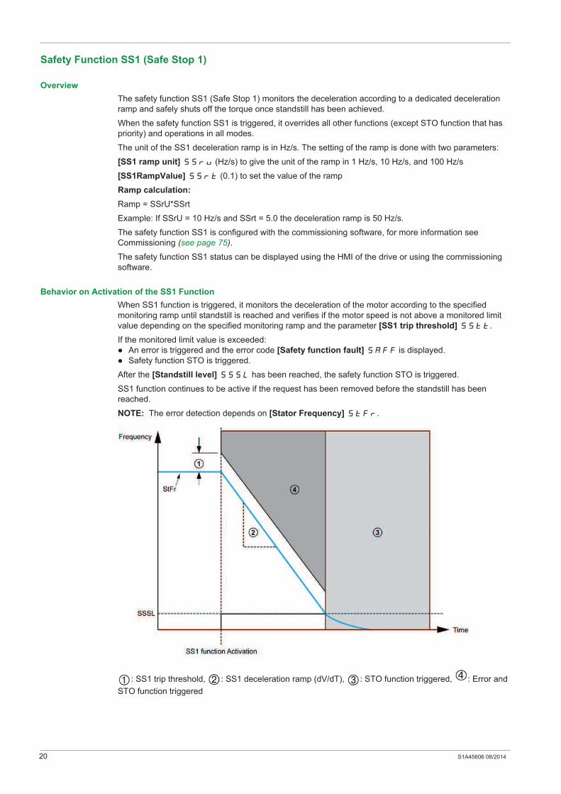
Behavior on Activation of the SS1 Function
When SS1 function is triggered, it monitors the deceleration of the motor according to the specified
monitoring ramp until standstill is reached and verifies if the motor speed is not above a monitored limit
value depending on the specified monitoring ramp and the parameter [SS1 trip threshold] SStt.
If the monitored limit value is exceeded:
An error is triggered and the error code [Safety function fault] SAFF is displayed.
Safety function STO is triggered.
After the [Standstill level] SSSL has been reached, the safety function STO is triggered.
SS1 function continues to be active if the request has been removed before the standstill has been
reached.
NOTE: The error detection depends on [Stator Frequency] StFr.
: SS1 trip threshold, : SS1 deceleration ramp (dV/dT), : STO function triggered, : Error and
STO function triggered
S1A45606 08/2014 21
Behavior on Deactivation of the SS1 Function
After an SS1 stop, send a new run command (even if the run command is set on level command).
SS1 Standard Reference
The SS1 function is defined in section 4.2.2.2 of standard IEC 61800-5-2:
The PDS(SR) (Power drive system suitable for use in safety-related applications) either:
Initiates and controls the motor deceleration rate within set limits to stop the motor and initiates the STO
function (see 4.2.2.2) when the motor speed is below a specified limit; or
Initiates and monitors the motor deceleration rate within set limits to stop the motor and initiates the STO
function when the motor speed is below a specified limit; or
Initiates the motor deceleration and initiates the STO function after an application-specific time delay.
NOTE: This safety function corresponds to a controlled stop in accordance with stop category 1 of IEC
60204-1.
Safety Function (SF) Level Capability for Safety Function SS1
Emergency Stop Category 1
An emergency stop must operate in such a way that, when it is activated, the hazardous movement of the
machinery is stopped and the machine is unable to start under any circumstances, even after the
emergency stop is released.
An emergency stop shall function either as a stop category 0 or as a stop category 1.
Stop category 1 is a controlled shut-down, whereby the energy supply to the motor is maintained to perform
the shut-down, and the energy supply is only interrupted when the shut-down has been completed.
Stop category 1 is equivalent to the [Safe Stop 1] SS1 function, as defined by standard EN 61800-5-2.
In addition to the requirements for stop (see 9.2.5.3 of IEC 60204-1), the emergency stop function has the
following requirements:
it shall override all other functions and operations in all modes.
This reset shall be possible only by a manual action at that location where the command has been
initiated. The reset of the command shall not restart the machinery but only permit restarting.
For the machine environment (IEC 60204-1 and machinery directive), when safety function SS1 is used to
manage an emergency stop category 1, the motor must not restart automatically when safety function SS1
has been triggered and deactivated (with or without a power cycle). This is the reason why an additional
safety module is required if the machine restarts automatically after the safety function SS1 has been
deactivated.
Function Configuration SIL
Safety Integrity Level
According to IEC 61-508
PL
Performance Level
According to ISO-13849
SS1 type C STO with Preventa module SIL2 PL d
STO and LI3 with Preventa module SIL 3 PL e
SS1 type B LI3 and LI4 SIL 2 PL d
LI5 and LI6 SIL 2 PL d
22 S1A45606 08/2014
Safety Function SLS (Safely-Limited Speed)
Overview
This function is used to limit the speed of a motor.
There are 6 types of SLS function:
SLS type 1: Limits the motor speed to the actual motor speed.
SLS type 2: Limits the motor speed to a value set using a parameter.
SLS type 3: Same as type 2 with specific behavior if the motor speed is above threshold value set using
a parameter.
SLS type 4: Limits the motor speed to a value set using a parameter. The direction of rotation can be
changed while the safety function is active.
SLS type 5: Same as type 4 with the specific behavior if the motor speed is above threshold value set
using a parameter.
SLS type 6: Same as type 4 with specific behavior if the motor speed is above threshold value set using
a parameter.
NOTE: SLS types 2 and 3 use (SLwt) [SLS Wait time] parameter to allow the motor to run under the
[standstill level ] SSSL for a given time after the safety function SLS has been activated.
The safety function SLS is configured with the commissioning software, for more information see
commissioning (see page 75).
The status of the safety function SLS can be displayed using the HMI of the drive or using the
commissioning software.
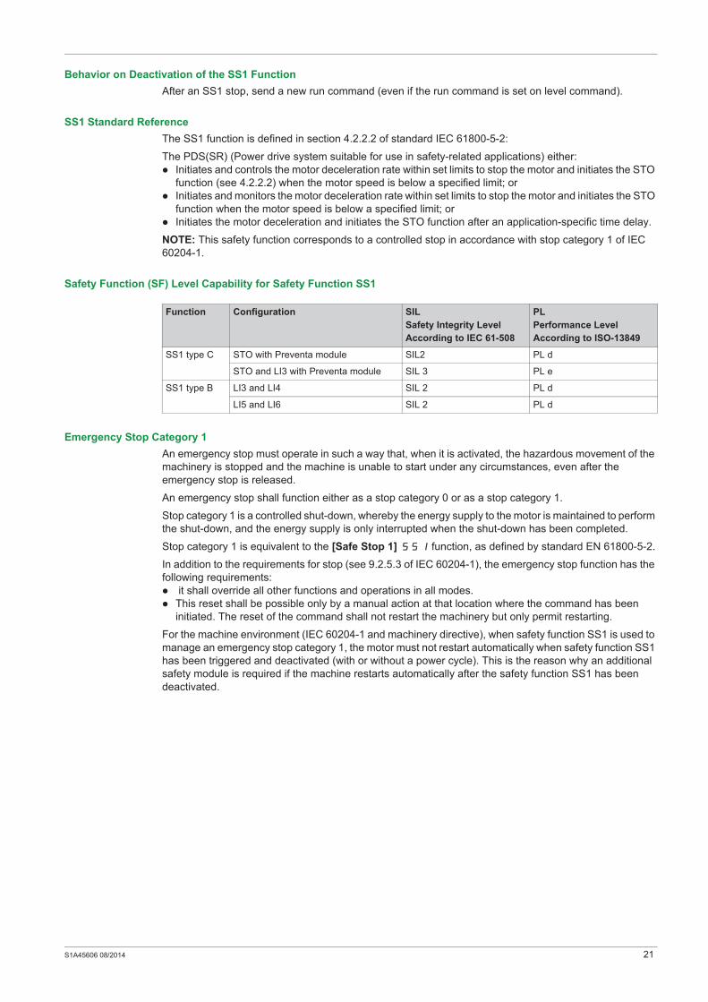
Behavior on Activation of the Safety Function SLS Type 1
: Error and STO function triggered, : Reference upper limit, : STO function triggered
When the safety function is activated:
If the [Stator Frequency] StFr is above the [SLS tolerance threshold] SLtt, the safety function
STO is triggered and an error is triggered with the error code [Safety function fault] SAFF.
If the [Stator Frequency] StFr is under the [SLS tolerance threshold] SLtt, the stator
frequency is limited to the actual stator frequency. The reference frequency will only vary between this
value and the standstill level SSSL.
While the function is activated:
If the[Stator Frequency] StFr decreases and reaches the [Standstill level] SSSL frequency, the
safety function STO is triggered.
If the [Stator Frequency] StFr increases and reaches [SLS tolerance threshold] SLtt, the
safety function STO is triggered and an error is triggered with the error code [Safety function fault]
SAFF.
S1A45606 08/2014 23
Behavior on Activation of the Safety Function SLS Type 2
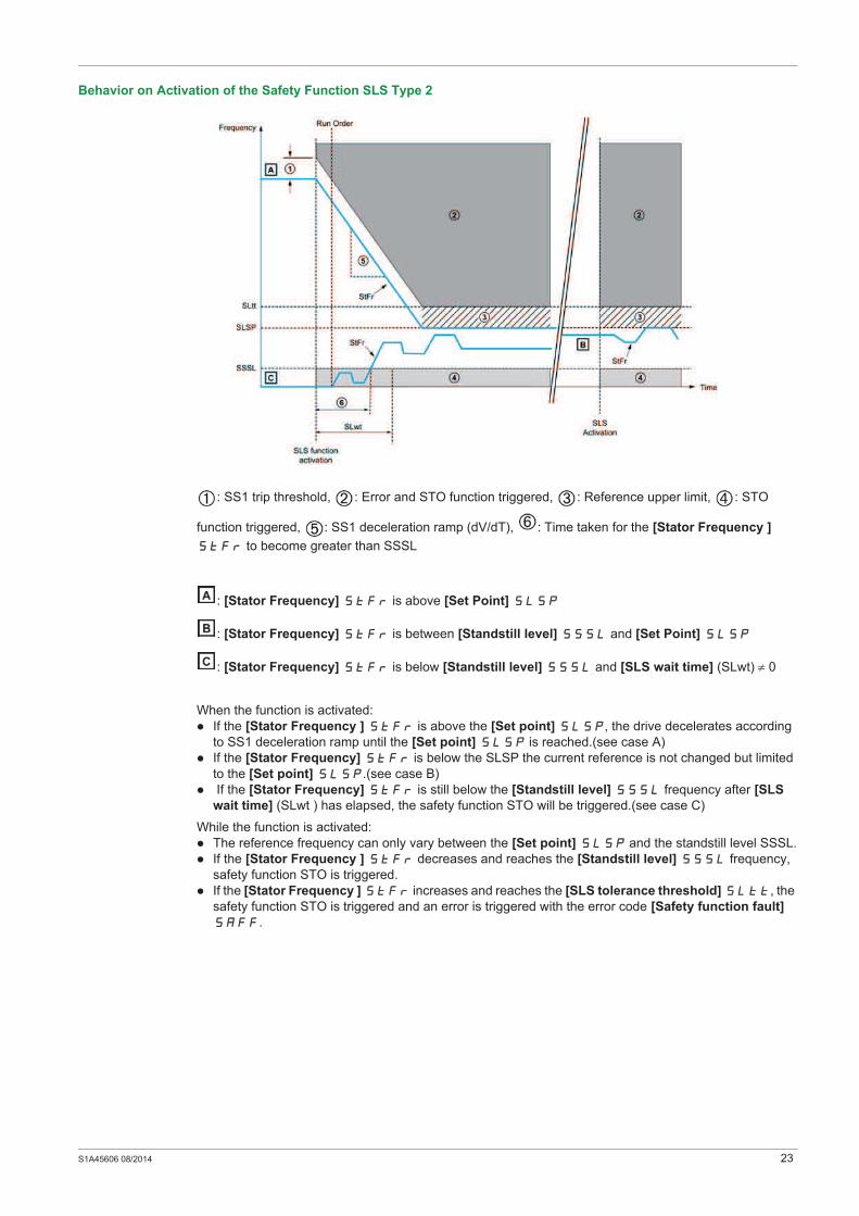
: SS1 trip threshold, : Error and STO function triggered, : Reference upper limit, : STO
function triggered, : SS1 deceleration ramp (dV/dT), : Time taken for the [Stator Frequency ]
StFr to become greater than SSSL
: [Stator Frequency] StFr is above [Set Point] SLSP
: [Stator Frequency] StFr is between [Standstill level] SSSL and [Set Point] SLSP
: [Stator Frequency] StFr is below [Standstill level] SSSL and [SLS wait time] (SLwt) 0
When the function is activated:
If the [Stator Frequency ] StFr is above the [Set point] SLSP, the drive decelerates according
to SS1 deceleration ramp until the [Set point] SLSP is reached.(see case A)
If the [Stator Frequency] StFr is below the SLSP the current reference is not changed but limited
to the [Set point] SLSP.(see case B)
If the [Stator Frequency] StFr is still below the [Standstill level] SSSL frequency after [SLS
wait time] (SLwt ) has elapsed, the safety function STO will be triggered.(see case C)
While the function is activated:
The reference frequency can only vary between the [Set point] SLSP and the standstill level SSSL.
If the [Stator Frequency ] StFr decreases and reaches the [Standstill level] SSSL frequency,
safety function STO is triggered.
If the [Stator Frequency ] StFr increases and reaches the [SLS tolerance threshold] SLtt, the
safety function STO is triggered and an error is triggered with the error code [Safety function fault]
SAFF.
24 S1A45606 08/2014
Behavior on Activation of the Safety Function SLS Type 3
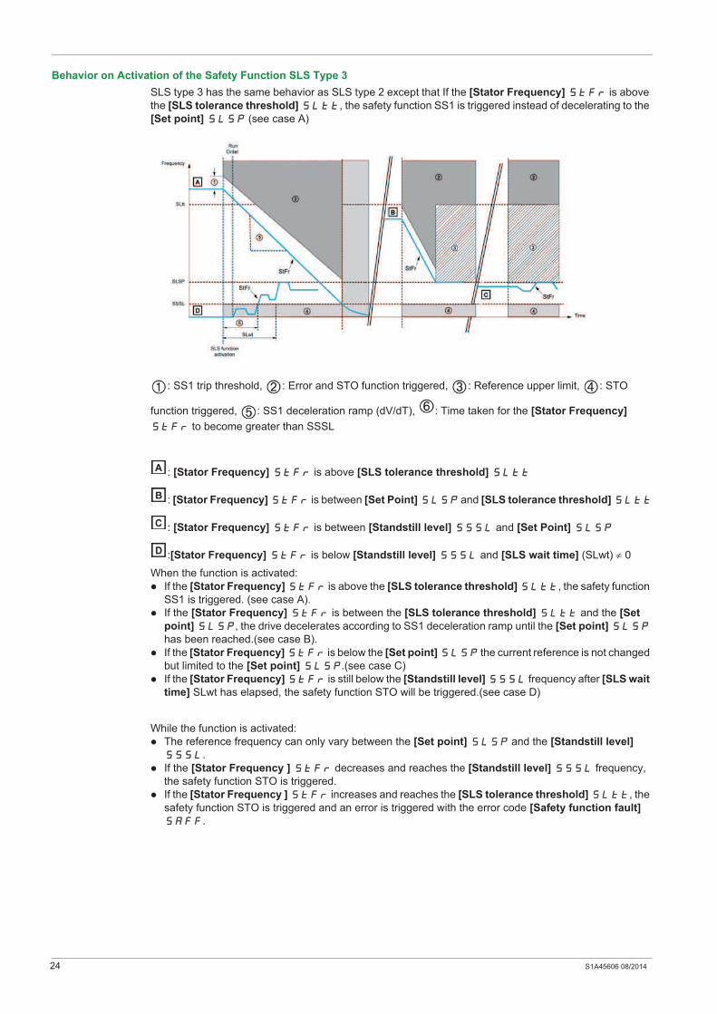
SLS type 3 has the same behavior as SLS type 2 except that If the [Stator Frequency] StFr is above
the [SLS tolerance threshold] SLtt, the safety function SS1 is triggered instead of decelerating to the
[Set point] SLSP (see case A)
: SS1 trip threshold, : Error and STO function triggered, : Reference upper limit, : STO
function triggered, : SS1 deceleration ramp (dV/dT), : Time taken for the [Stator Frequency]
StFr to become greater than SSSL
: [Stator Frequency] StFr is above [SLS tolerance threshold] SLtt
: [Stator Frequency] StFr is between [Set Point] SLSP and [SLS tolerance threshold] SLtt
: [Stator Frequency] StFr is between [Standstill level] SSSL and [Set Point] SLSP
:[Stator Frequency] StFr is below [Standstill level] SSSL and [SLS wait time] (SLwt) 0
When the function is activated:
If the [Stator Frequency] StFr is above the [SLS tolerance threshold] SLtt, the safety function
SS1 is triggered. (see case A).
If the [Stator Frequency] StFr is between the [SLS tolerance threshold] SLtt and the [Set
point] SLSP, the drive decelerates according to SS1 deceleration ramp until the [Set point] SLSP
has been reached.(see case B).
If the [Stator Frequency] StFr is below the [Set point] SLSP the current reference is not changed
but limited to the [Set point] SLSP.(see case C)
If the [Stator Frequency] StFr is still below the [Standstill level] SSSL frequency after [SLS wait
time] SLwt has elapsed, the safety function STO will be triggered.(see case D)
While the function is activated:
The reference frequency can only vary between the [Set point] SLSP and the [Standstill level]
SSSL.
If the [Stator Frequency ] StFr decreases and reaches the [Standstill level] SSSL frequency,
the safety function STO is triggered.
If the [Stator Frequency ] StFr increases and reaches the [SLS tolerance threshold] SLtt, the
safety function STO is triggered and an error is triggered with the error code [Safety function fault]
SAFF.

S1A45606 08/2014 25
Behavior on Activation of the Safety Function SLS Type 4
Error and STO function triggered, SS1 trip threshold, SS1 deceleration ramp (dv/dt),
reference upper limit
: [Stator Frequency] StFr is above [SLS tolerance threshold] SLtt
: [Stator Frequency] StFr is between [Set Point] SLSP and [SLS tolerance threshold] SLtt
: [Stator Frequency] StFr is below [Set Point] SLSP
NOTE: If the SLTT SLSP for SLS type 4, SAFF fault is triggered.
When the function is activated:
If the [Stator Frequency] StFr is above the [SLS tolerance threshold] SLtt, the safety function
STO is triggered with the error code [Safety function fault] SAFF.(see case A)
If the [Stator Frequency] StFr is between the [SLS tolerance threshold] SLtt and the [Set
point] SLSP, the drive decelerates according to SS1 deceleration ramp until the [Set point] SLSP
has been reached.(see case B)
If the [Stator Frequency] StFr is below the [Set point] SLSP, the current reference is not
changed but limited to the [Set point] SLSP.(see case C).
While the function is activated:
The reference frequency can vary between the [Set point] SLSP in both forward and reverse
directions.
If the [Stator Frequency] StFr increases and reaches [SLS tolerance threshold] SLtt, the
safety function STO is triggered and an error is triggered with the error code [Safety function fault]
SAFF.

26 S1A45606 08/2014
Behavior on Activation of the Safety Function SLS Type 5
: Error and STO function triggered, : SS1 trip threshold, : SS1 deceleration ramp (dv/dt), :
Reference upper limit
: [Stator Frequency] StFr is above [SLS tolerance threshold] SLtt
: [Stator Frequency] StFr is between [Set Point] SLSP and [SLS tolerance threshold] SLtt
: [Stator Frequency] StFr is below [Set Point] SLSP
When the function is activated:
If the [Stator Frequency] StFr is above the [SLS tolerance threshold] SLtt, the drive
decelerates according to SS1 deceleration ramp until the [Set point] SLSP has been reached. (see
case A)
If the [Stator Frequency] StFr is between the [SLS tolerance threshold] SLtt and the [Set
point] SLSP, the drive decelerates according to SS1 deceleration ramp until the [Set point] SLSP
has been reached.(see case B)
If the [Stator Frequency] StFr is below the [Set point] SLSP, the current reference is not
changed but limited to the [Set point] SLSP.(see case C).
While the function is activated:
The reference frequency can vary between the [Set point] SLSP in both forward and reverse
directions.
If the [Stator Frequency] StFr increases and reaches [SLS tolerance threshold] SLtt, the
safety function STO is triggered and an error is triggered with the error code [Safety function fault]
SAFF.

S1A45606 08/2014 27
Behavior on Activation of the Safety Function SLS Type 6
: Error and STO function triggered, : SS1 trip threshold, : SS1 deceleration ramp (dV/dT) :
Reference upper limit, : STO function triggered.
: [Stator Frequency] StFr is above [SLS tolerance threshold] SLtt
: [Stator Frequency] StFr is between [Set Point] SLSP and [SLS tolerance threshold] SLtt
: [Stator Frequency] StFr is below [Set Point] SLSP
When the function is activated:
If the [Stator Frequency] StFr is above the [SLS tolerance threshold] SLtt, the drive
decelerates according to SS1 deceleration ramp until 0 Hz has been reached (see case A).
If the [Stator Frequency] StFr is between the [SLS tolerance threshold] SLtt and the [Set
point] SLSP, the drive decelerates according to SS1 deceleration ramp until the [Set point] SLSP
has been reached.(see case B)
If the [Stator Frequency] StFr is below the [Set point] SLSP, the current reference is not
changed but limited to the [Set point] SLSP.(see case C).
While the function is activated:
The reference frequency can vary between the [Set point] SLSP in both forward and reverse
directions.
If the [Stator Frequency] StFr increases and reaches [SLS tolerance threshold] SLtt, the
safety function STO is triggered and an error is triggered with the error code [Safety function fault]
SAFF.

28 S1A45606 08/2014
Behavior on Deactivation of the Safety Function SLS for All SLS Types
SLS Standards References
The safety function SLS is defined in section 4.2.3.4 of standard IEC 61800-5-2 The SLS function helps to
prevent the motor from exceeding the specified speed limit.
Safety Function (SF) Level for Safety Function SLS
If... Then ...
The drive is still running when the function is deactivated The reference frequency of the active channel is applied.
Safety function STO has been triggered and the drive is
not in fault state.
A new run command must be applied.
The safety function SLS type 2, 3, 4 is deactivated while
the drive decelerates to the [Set point] SLSP
according to SS1 deceleration ramp.
The safety function SLS type 3 is deactivated while the
safety function SS1 has been triggered
The safety function SLS remains activated until the [Set
point] SLSP has been reached.
STO is triggered when [Standstill level] SSSL is
reached and a new run command must be applied.
a stop command is applied The safety function SLS remains active and the drive
decelerates until standstill is reached.
For SLS type 1, 2, or 3 STO function is triggered when the
[Stator Frequency] StFr decreases and reaches the
[Standstill level] SSSL frequency.
an error is detected The safety function SLS remains active and the drive stops
according to the configured error response.
For SLS type 1, 2, or 3 STO function will be triggered after
the [Standstill level] SSSL frequency has been
reached.The drive can be reset after the cause is cleared.
Configuration SIL
Safety Integrity Level According to IEC 61-508
PL
Performance level According to ISO-13849
LI3 and LI4 SIL 2 PL d
LI5 and LI6 SIL 2 PL d
S1A45606 08/2014 29
Calculation of Safety Related Parameters
Chapter 3Calculation of Safety Related Parameters
What Is in This Chapter?
This chapter contains the following topics:
Topic Page
SLS Type 1 30
SLS Type 2, Type 3, Type 4, Type 5, and Type 6 32
SS1 35
30 S1A45606 08/2014
SLS Type 1
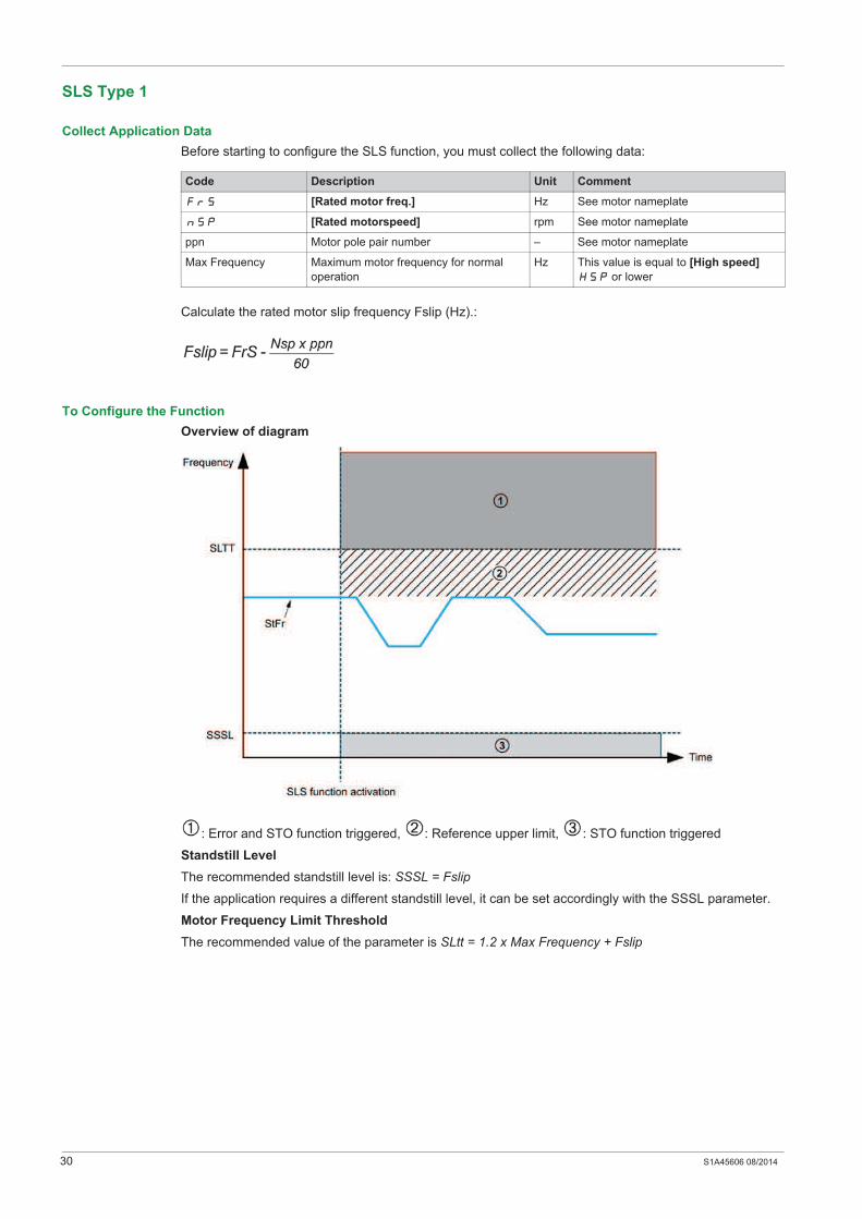
Collect Application Data
Before starting to configure the SLS function, you must collect the following data:
Calculate the rated motor slip frequency Fslip (Hz).:
To Configure the Function
Overview of diagram
: Error and STO function triggered, : Reference upper limit, : STO function triggered
Standstill Level
The recommended standstill level is: SSSL = Fslip
If the application requires a different standstill level, it can be set accordingly with the SSSL parameter.
Motor Frequency Limit Threshold
The recommended value of the parameter is SLtt = 1.2 x Max Frequency + Fslip
Code Description Unit Comment
FrS [Rated motor freq.] Hz See motor nameplate
nSp [Rated motorspeed] rpm See motor nameplate
ppn Motor pole pair number – See motor nameplate
Max Frequency Maximum motor frequency for normal
operation
Hz This value is equal to [High speed]
HSP or lower
S1A45606 08/2014 31
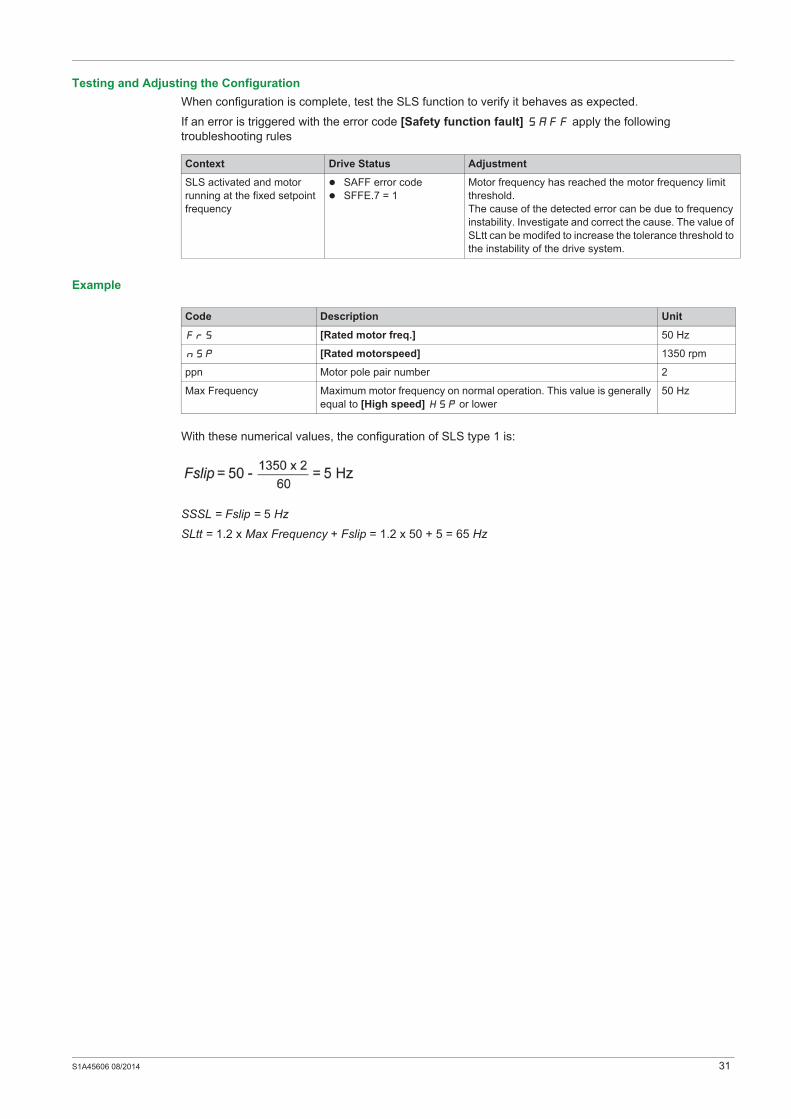
Testing and Adjusting the Configuration
When configuration is complete, test the SLS function to verify it behaves as expected.
If an error is triggered with the error code [Safety function fault] SAFF apply the following
troubleshooting rules
Example
With these numerical values, the configuration of SLS type 1 is:
SSSL = Fslip = 5 Hz
SLtt = 1.2 x Max Frequency + Fslip = 1.2 x 50 + 5 = 65 Hz
Context Drive Status Adjustment
SLS activated and motor
running at the fixed setpoint
frequency
SAFF error code
SFFE.7 = 1
Motor frequency has reached the motor frequency limit
threshold.
The cause of the detected error can be due to frequency
instability. Investigate and correct the cause. The value of
SLtt can be modifed to increase the tolerance threshold to
the instability of the drive system.
Code Description Unit
FrS [Rated motor freq.] 50 Hz
nSp [Rated motorspeed] 1350 rpm
ppn Motor pole pair number 2
Max Frequency Maximum motor frequency on normal operation. This value is generally
equal to [High speed] HSP or lower
50 Hz
32 S1A45606 08/2014
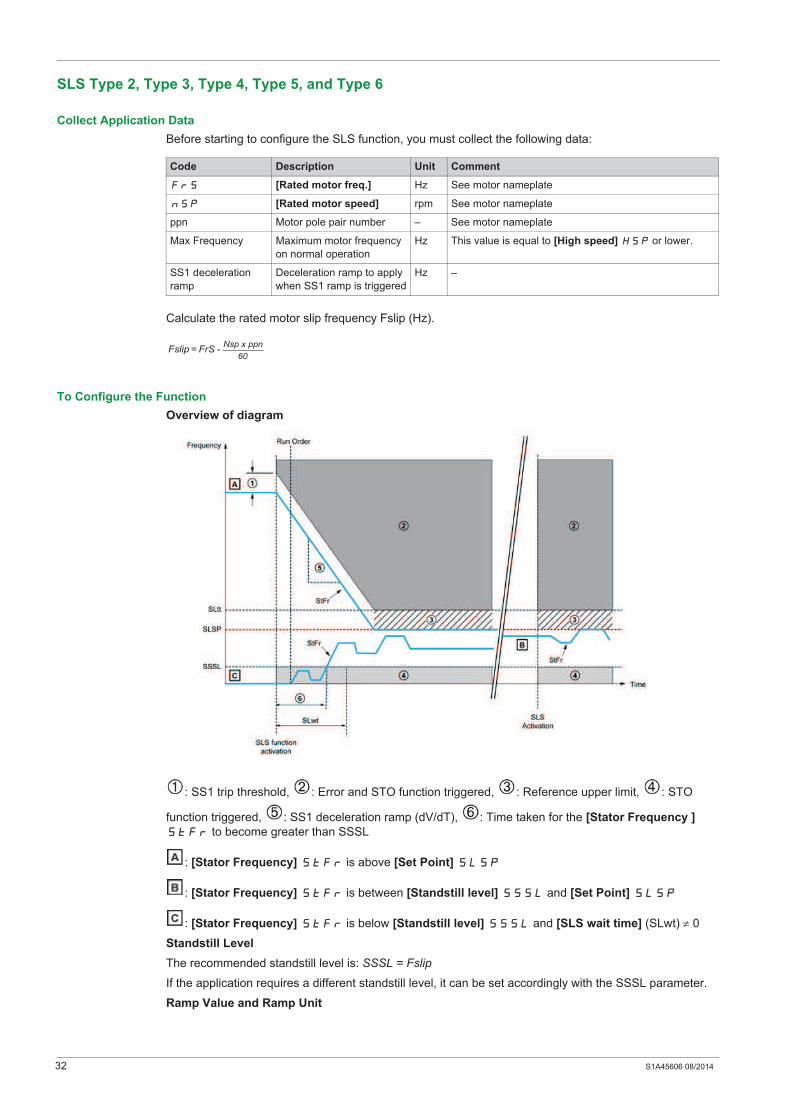
SLS Type 2, Type 3, Type 4, Type 5, and Type 6
Collect Application Data
Before starting to configure the SLS function, you must collect the following data:
Calculate the rated motor slip frequency Fslip (Hz).
To Configure the Function
Overview of diagram
: SS1 trip threshold, : Error and STO function triggered, : Reference upper limit, : STO
function triggered, : SS1 deceleration ramp (dV/dT), : Time taken for the [Stator Frequency ]
StFr to become greater than SSSL
: [Stator Frequency] StFr is above [Set Point] SLSP
: [Stator Frequency] StFr is between [Standstill level] SSSL and [Set Point] SLSP
: [Stator Frequency] StFr is below [Standstill level] SSSL and [SLS wait time] (SLwt) 0
Standstill Level
The recommended standstill level is: SSSL = Fslip
If the application requires a different standstill level, it can be set accordingly with the SSSL parameter.
Ramp Value and Ramp Unit
Code Description Unit Comment
FrS [Rated motor freq.] Hz See motor nameplate
nSp [Rated motor speed] rpm See motor nameplate
ppn Motor pole pair number – See motor nameplate
Max Frequency Maximum motor frequency
on normal operation
Hz This value is equal to [High speed] HSP or lower.
SS1 deceleration
ramp
Deceleration ramp to apply
when SS1 ramp is triggered
Hz –
Nsp x ppn
60Fslip = FrS -

S1A45606 08/2014 33
Set SSrt (ramp value) and SSrU (ramp unit) parameters according to the deceleration ramp to apply when
the safety function SS1 is triggered.
Ramp calculation: Ramp = SSrU*SSrt
Example 1: If SSrU = 1 Hz/s and SSrt = 500.0 the deceleration ramp is 500.0 Hz/s and the accuracy is
0.1 Hz
Example 2: If SSrU = 10 Hz/s and SSrt = 50.0 the deceleration ramp is 500 Hz/s and the accuracy is 1 Hz
Use the table to set the correct accuracy according to the deceleration ramp to apply when the safety
function SS1 is triggered:
SLS Setpoint
Set the SLS setpoint parameter (SLSP) to: SLSP= Fsetpoint (SLS)
Motor Frequency and ramp Limit Threshold
The recommended motor frequency limit threshold is SLtt = 1.2 x SLSP + Fslip and the recommended SS1
ramp limit threshold is: SStt = 0.2 x Max Frequency
SLS Wait time
Set the [SLS wait time] (SLwt) greater than 0 ms to to allow the motor to run under the [standstill level]
SSSL for a given time after the safety function SLS has been activated.
NOTE: When SLS Type 4 is configured, [SLS wait time] (SLwt) must be set to 0 otherwise an error is
triggered and the error code [Safety function fault] SAFF is displayed
Testing and Adjusting the Configuration
When configuration is complete, test the SLS function to verify that it behaves as expected.
If an error is triggered with the error code [Safety function fault] SAFF, apply the following
troubleshooting rules
Min Max Accuracy SSrt SSrU
0.1 Hz/s 599 Hz/s 0.1 Hz/s 1 Hz/s SS1 deceleration ramp
599 Hz/s 5990 Hz/s 1 Hz/s 10 Hz/s SS1 deceleration ramp/10
5990 Hz/s 59900 Hz/s 10 Hz/s 100 Hz/s SS1 deceleration ramp/100
Context Drive Status Adjustment
SLS activated and
deceleration ramp in
progress
SAFF error code
SFFE.3 = 1
Motor frequency has reached the motor frequency limit threshold.
The cause of the detected error can be due to frequency instability.
Investigate and correct the cause. The value of SLtt can be modified to
increase the tolerance threshold to the instability of the drive system.

34 S1A45606 08/2014
Example
With these numerical values, the configuration of SLS type 2, 3, and 4 is:
SSSL = Fslip = 5 Hz
SSrU = 1 Hz/s and SSrt = 20.0 for SS1 deceleration ramp = 20 Hz/s (accuracy is 0.1 Hz)
SLSP = Fsetpoint(SLS) = 15 Hz
SLtt = 1.2 x SLSP + Fslip = 1.2 x 15 + 5 = 23 Hz
SStt = 0.2 x Max Frequency = 0.2 * 50 = 10 Hz
In this example, the frequency oscillations are allowed to be higher than SLtt for 350 ms.
SLS activated and end
of ramp at SLSP
frequency
SAFF error code
SFFE.3 = 1
or
SFFE.7 = 1
Motor frequency stabilization at SLSP takes too long and has reached
the safety function error detection condition.
: Safety function error detection, Tosc: T oscillation, F: Frequency
The oscillations must be lower than SLtt before the time T(oscillation)
elapses.
If the condition is not followed, an error is triggered and the error code
[Safety function fault] SAFF is displayed
The relationship between SStt and T(oscillation) is:
Motor frequency has reached the motor frequency limit threshold.
The cause of the detected error can be due to frequency instability.
Investigate and correct the cause. The value of SStt can be modified to
increase the tolerance threshold to the oscillations of the drive system.
SLS activated and
motor running at SLSP
frequency
SAFF error code
SFFE.7 = 1
Motor frequency has reached the motor frequency limit threshold.
The cause of the detected error can be due to frequency instability.
Investigate and correct the cause. The value of SLtt can be modified to
increase the tolerance threshold to the instability of the drive system.
Context Drive Status Adjustment
Code Description Unit
FrS Rated motor frequency 50 Hz
nSp Rated motor speed 1350 rpm
ppn Motor pole pair number 2
Max Frequency Maximum motor frequency on normal operation. This value is equal to
[High speed] HSP or lower
50 Hz
Fsetpoint(SLS) Motor frequency setpoint 15 Hz
SS1 deceleration ramp Deceleration ramp to apply when SS1 is triggered 20 Hz/s
1350 x 2
60Fslip = 50 - = 5 Hz
S1A45606 08/2014 35
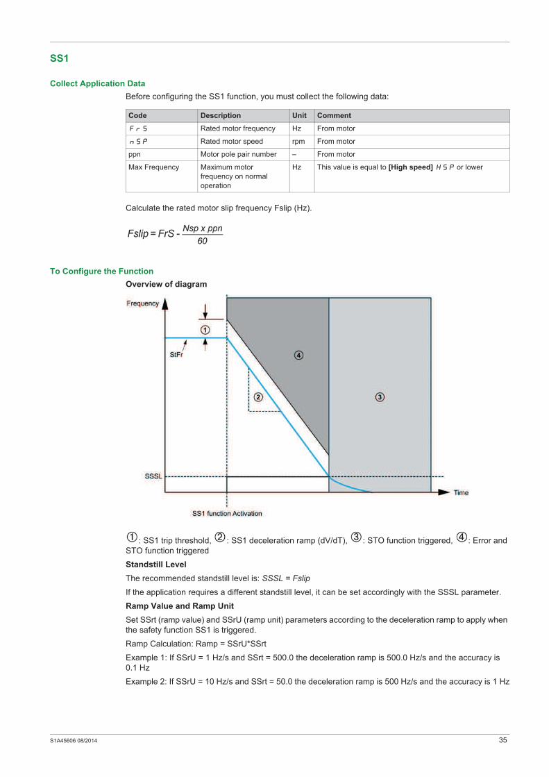
SS1
Collect Application Data
Before configuring the SS1 function, you must collect the following data:
Calculate the rated motor slip frequency Fslip (Hz).
To Configure the Function
Overview of diagram
: SS1 trip threshold, : SS1 deceleration ramp (dV/dT), : STO function triggered, : Error and
STO function triggered
Standstill Level
The recommended standstill level is: SSSL = Fslip
If the application requires a different standstill level, it can be set accordingly with the SSSL parameter.
Ramp Value and Ramp Unit
Set SSrt (ramp value) and SSrU (ramp unit) parameters according to the deceleration ramp to apply when
the safety function SS1 is triggered.
Ramp Calculation: Ramp = SSrU*SSrt
Example 1: If SSrU = 1 Hz/s and SSrt = 500.0 the deceleration ramp is 500.0 Hz/s and the accuracy is
0.1 Hz
Example 2: If SSrU = 10 Hz/s and SSrt = 50.0 the deceleration ramp is 500 Hz/s and the accuracy is 1 Hz
Code Description Unit Comment
FrS Rated motor frequency Hz From motor
nSp Rated motor speed rpm From motor
ppn Motor pole pair number – From motor
Max Frequency Maximum motor
frequency on normal
operation
Hz This value is equal to [High speed] HSP or lower

36 S1A45606 08/2014
Use the table to set the correct accuracy according to the deceleration ramp to apply when the safety
function SS1 is triggered:
Ramp Limit Threshold
The SS1 ramp trip threshold is calculated by: SStt = 0.2 x Max Frequency
This value is equal to [High speed] HSP or lower
Testing and Adjusting the Configuration
When configuration is complete, test the safety function SS1 to verify that it behaves as expected.
If an error is triggered with the error code [Safety function fault] SAFF, apply the following
troubleshooting rules
Example
With these numerical values, the configuration of SS1 is:
SSSL = Fslip = 5 Hz
SSrU = 1 Hz/s and SSrt = 20.0 for SS1 deceleration ramp = 20 Hz/s (accuracy is 0.1 Hz)
SStt = 0.2 x Max Frequency = 0.2 x 50 = 10 Hz
Min Max Accuracy SSrU SSrt
0.1 Hz/s 599 Hz/s 0.1 Hz/s 1 Hz/s SS1 deceleration ramp
599 Hz/s 5990 Hz/s 1 Hz/s 10 Hz/s SS1 deceleration ramp/10
5990 Hz/s 59900 Hz/s 10 Hz/s 100 Hz/s SS1 deceleration ramp/100
Context Drive Status Adjustment
SS1 activated and the
[Standstill level] SSSL
has not yet been reached
SAFF error code
SFFE.3 = 1
Motor frequency has reached the motor frequency limit
threshold.
The cause of the detected error can be due to frequency
instability. Investigate and correct the cause. The value of
SStt can be modified to increase the tolerance threshold
to the instability of the drive system.
Code Description Unit
FrS Rated motor frequency 50 Hz
nSp Rated motor speed 1350 rpm
ppn Motor pole pair number 2
Max Frequency Maximum motor frequency on normal operation 50 Hz
SS1 deceleration ramp Deceleration ramp to apply when SS1 is triggered 20 Hz/s

S1A45606 08/2014 37
Behavior of Safety Functions
Chapter 4Behavior of Safety Functions
What Is in This Chapter?
This chapter contains the following topics:
Topic Page
Limitations 38
Detected Fault Inhibition 39
Priority Between Safety Functions 40
Factory Settings 41
Configuration Download 42
Priority Between Safety Functions and No Safety-Related Functions 43

38 S1A45606 08/2014
Limitations
Type Of Motor
The safety functions SLS and SS1 on ATV32 are only applicable for asynchronous motors with open-
loop control profile.
The safety function STO can be used with synchronous and asynchronous motors.
Prerequisites for Using Safety Functions
Following conditions have to be fulfilled for correct operation:
The motor size is adequate for the application and is not at the limit of its capacity.
The drive size has been correctly chosen for the line supply, sequence, motor, and application and is
not at the limit of their capacities as stated in the catalog.
If required, the appropriate options are used.
Example: dynamic braking resistor or motor choke.
The drive is correctly set up with the correct speed loop and torque characteristics for the application;
the reference frequency profile applied to the drive control loop is followed.
Requirements on Logical Inputs
Sink mode must not been used with the safety function. If you use the safety function, you need to wire
the logic inputs in source mode.
PTC on LI6 is incompatible with the safety function set on this input. If you are using the safety function
on LI6, do not set the PTC switch to PTC
If you are using the pulse input, you cannot set the safety function on LI5 at the same time.

S1A45606 08/2014 39
Detected Fault Inhibition
When a safety function has been configured, the error [Safety Function Fault] SAFF cannot be
inhibited by the function [Fault Inhibit assign.] InH
40 S1A45606 08/2014
Priority Between Safety Functions
1. The safety function STO has the highest priority. If the safety function STO is triggered, a Safe Torque
Off is performed regardless of which other functions are active.
2. The safety function SS1 has medium priority in relation to the other safety functions.
3. The safety function SLS has the lowest priority.

S1A45606 08/2014 41
Factory Settings
If the safety functions are configured and you restore the factory settings, only the parameters which are
not safety-related will be reset to the factory setting. The settings of safety-related parameters can only be
reset using the commissioning software, for more information see Commissioning (see page 75).
42 S1A45606 08/2014
Configuration Download
You can transfer a configuration in all situations. If a safety function has been configured, the functions
using these same logic inputs will not be configured.
For example: If the downloaded configuration has functions (Preset speed,...) on LI3-4-5-6 and if the drive
has a safety function configured on these logic inputs, safety function will not be erased. It is the functions
that have the same logic input as safety functions that are not transferred. Multiconfiguration/multimotor
and macro configuration obey the same rules.

S1A45606 08/2014 43
Priority Between Safety Functions and No Safety-Related Functions
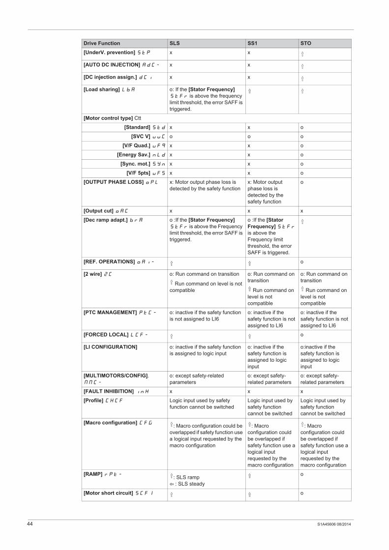
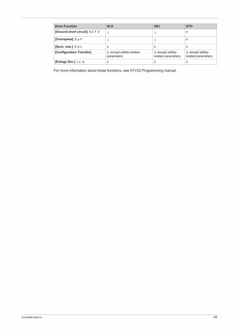
Priority Table
o: Compatible functions
x: Incompatible functions
: The function indicated by the arrow has priority over the other.
Drive Function SLS SS1 STO
[HIGH SPEED HOISTING] HSH-
[+/- SPEED] UPd-
[Skip Frequency] JPF o o
[Low speed time out] tLS
[MULTIMOTORS] MMC- Configuration must be consistent with the 3 motors o
[PRESET SPEEDS] PSS-
[PID REGULATOR] PId- o o
[RAMP] rPt-
[Freewheel stop ass. ]nSt
[Fast stop assign.] FSt
[TRAVERSE CONTROL] tr0- o: both function configurations
should not overlap
o: motor frequency can exceed
SLS set-point (but not the motor
frequency limit threshold)
[EXTERNAL FAULT] EtF- B: NST
x: DCI
: fast, ramp, fallback, maintain
B: NST
x: DCI
: fast, ramp,
fallback, maintain
B: NST
: DCI
: fast, ramp,
fallback, maintain
[AUTOMATIC RESTART] Atr-
[FAULT RESET] rSt-
[JOG] JOG-
[STOP CONFIGURATION] Stt-
[Ramp stop] rMP: SLS ramp
: SLS steady
[Fast stop] FSt: SLS ramp
: SLS steady
[DC injection] dCI x x
[Freewheel] nSt
[+/-SPEED AROUND REF.]
SrE-
[POSITIONING BY SENSORS]
LPO-: SLS ramp
& position is not respected
: Position is not
respected
[RP input] PFrC o: if the safety function is not
assigned to LI5
o: if the safety
function is not
assigned to LI5
o: if the safety
function is not
assigned to LI5
[Underload Detection] ULF
[Overload Detection] OLC
[Rope slack config.] rSd x x x
44 S1A45606 08/2014
[UnderV. prevention] StP x x
[AUTO DC INJECTION] AdC- x x
[DC injection assign.] dCI x x
[Load sharing] LbA o: If the [Stator Frequency]
StFr is above the frequency
limit threshold, the error SAFF is
triggered.
[Motor control type] Ctt
[Standard] Std x x o
[SVC V] UUC o o o
[V/F Quad.] UFq x x o
[Energy Sav.] nLd x x o
[Sync. mot.] SYn x x o
[V/F 5pts] UF5 x x o
[OUTPUT PHASE LOSS] OPL x: Motor output phase loss is
detected by the safety function
x: Motor output
phase loss is
detected by the
safety function
o
[Output cut] OAC x x x
[Dec ramp adapt.] brA o :If the [Stator Frequency]
StFr is above the Frequency
limit threshold, the error SAFF is
triggered.
o :If the [Stator
Frequency] StFr
is above the
Frequency limit
threshold, the error
SAFF is triggered.
[REF. OPERATIONS] OAI- o
[2 wire] 2C o: Run command on transition
Run command on level is not
compatible
o: Run command on
transition
Run command on
level is not
compatible
o: Run command on
transition
Run command on
level is not
compatible
[PTC MANAGEMENT] PtC- o: inactive if the safety function
is not assigned to LI6
o: inactive if the
safety function is not
assigned to LI6
o: inactive if the
safety function is not
assigned to LI6
[FORCED LOCAL] LCF- o
[LI CONFIGURATION] o: inactive if the safety function
is assigned to logic input
o: inactive if the
safety function is
assigned to logic
input
o:inactive if the
safety function is
assigned to logic
input
[MULTIMOTORS/CONFIG].
MMC-
o: except safety-related
parameters
o: except safety-
related parameters
o: except safety-
related parameters
[FAULT INHIBITION] InH x x x
[Profile] CHCF Logic input used by safety
function cannot be switched
Logic input used by
safety function
cannot be switched
Logic input used by
safety function
cannot be switched
[Macro configuration] CFG: Macro configuration could be
overlapped if safety function use
a logical input requested by the
macro configuration
: Macro
configuration could
be overlapped if
safety function use a
logical input
requested by the
macro configuration
: Macro
configuration could
be overlapped if
safety function use a
logical input
requested by the
macro configuration
[RAMP] rPt-: SLS ramp
B : SLS steady
o
[Motor short circuit] SCF1 o
Drive Function SLS SS1 STO
S1A45606 08/2014 45
For more information about these functions, see ATV32 Programming manual.
[Ground short circuit] SCF3 o
[Overspeed] SOF o
[Sync. mot.] SYn x x o
[Configuration Transfer] o: except safety-related
parameters
o: except safety-
related parameters
o: except safety-
related parameters
[Energy Sav.] nLd x x o
Drive Function SLS SS1 STO

46 S1A45606 08/2014

S1A45606 08/2014 47
Safety Functions Visualization by HMI
Chapter 5Safety Functions Visualization by HMI
What Is in This Chapter?
This chapter contains the following topics:
Topic Page
Status of Safety Functions 48
Dedicated HMI 49
Error Code Description 50

48 S1A45606 08/2014
Status of Safety Functions
Description
The status of the safety functions can be displayed using the HMI of the drive or using the commissioning
software. HMI of the drive can be the local HMI on the product or the graphic display terminal or the remote
display terminal. There is one register for each safety function. See introduction (see page 12) for more
information about the safety functions.
To access these registers with an HMI: [2 MONITORING] MOn- --> [MONIT. SAFETY] SAF-
[STO status] StOS: Status of the safety function STO (Safe Torque Off)
[SLS status] SLSS: Status of the safety function SLS (Safely-Limited Speed)
[SS1 status] SS1S: Status of the safety function SS1 (Safe Stop 1)
The status registers are not approved for any type of safety-related use.
For more information about these registers, see ATV32 Visualization and Status of Safety Functions
(see page 81) on www.schneider-electric.com.

S1A45606 08/2014 49
Dedicated HMI
Description
When a safety function has been triggered, some information is displayed.
Example with the local HMI of the product when the safety function SS1 has been triggered:
: Display alternately the name of the safety function SS1 and the current display parameter as long as
the motor decelerates according to the specified monitoring ramp until standstill is reached, After the
[Standstill level] SSSL has been reached, the safety function STO is triggered and displayed

50 S1A45606 08/2014
Error Code Description
Description
When an error is detected by the safety function, the drive displays [Safety function fault] (SAFF). This
detected error can only be reset after powering the drive OFF/ON.
for more information, you can access to the registers to find out the possible reasons for triggering.
These registers can be displayed using the graphic display terminal or the commissioning software:
[DRIVE MENU] --> [MONITORING] --> [DIAGNOSTICS] --> [MORE FAULT INFO]
SFFE [Safety Function Error Register]
This register is reset after powering OFF/ON.
This register can also be accessed from [DRIVE MENU] --> [MONITORING] --> [MONIT. SAFETY]
SAF1 [Safety Fault Register 1]
This is an application control error register.
Bit Description
Bit0=1 Logic inputs debounce time-out (verify value of debounce time LIDT according to the application)
Bit1 Reserved
Bit2=1 Motor speed sign has changed during SS1 ramp
Bit3=1 Motor speed has reached the frequency limit threshold during SS1 ramp.
Bit4 Reserved
Bit5 Reserved
Bit6=1 Motor speed sign has changed during SLS limitation
Bit7=1 Motor speed has reached the frequency limit threshold during SS1 ramp.
Bit8 Reserved
Bit9 Reserved
Bit10 Reserved
Bit11 Reserved
Bit12 Reserved
Bit13=1 Not possible to measure the motor speed (verify the motor wiring connection)
Bit14=1 Motor ground short-circuit detected (verify the motor wiring connection)
Bit15=1 Motor phase to phase short-circuit detected (verify the motor wiring connection)
Bit Description
Bit0=1 PWRM consistency detected error
Bit1=1 Safety functions parameters detected error
Bit2=1 Application auto test has detected an error
Bit3=1 Diagnostic verification of safety function has detected an error
Bit4=1 Logical input diagnostic has detected an error
Bit5=1 Application hardware watchdog active
Bit6=1 Application watchdog management active
Bit7=1 Motor control detected error
Bit8=1 Internal serial link core detected error
Bit9=1 Logical input activation detected error
Bit10=1 Safe Torque Off function has triggered an error
Bit11=1 Application interface has detected an error of the safety functions
Bit12=1 Safe Stop 1 function has detected an error of the safety functions
Bit13=1 Safely Limited Speed function has triggered an error
Bit14=1 Motor data is corrupted
Bit15=1 Internal serial link data flow detected error
S1A45606 08/2014 51
This register is reset after powering OFF/ON.
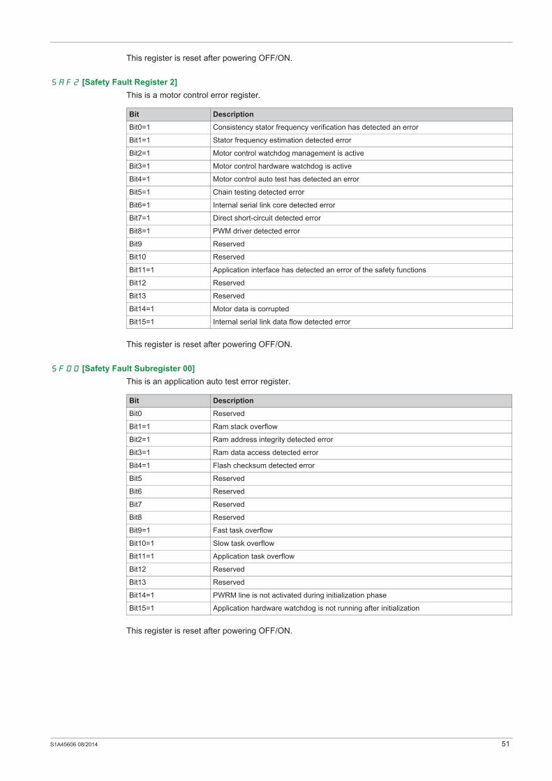
SAF2 [Safety Fault Register 2]
This is a motor control error register.
This register is reset after powering OFF/ON.
SF00 [Safety Fault Subregister 00]
This is an application auto test error register.
This register is reset after powering OFF/ON.
Bit Description
Bit0=1 Consistency stator frequency verification has detected an error
Bit1=1 Stator frequency estimation detected error
Bit2=1 Motor control watchdog management is active
Bit3=1 Motor control hardware watchdog is active
Bit4=1 Motor control auto test has detected an error
Bit5=1 Chain testing detected error
Bit6=1 Internal serial link core detected error
Bit7=1 Direct short-circuit detected error
Bit8=1 PWM driver detected error
Bit9 Reserved
Bit10 Reserved
Bit11=1 Application interface has detected an error of the safety functions
Bit12 Reserved
Bit13 Reserved
Bit14=1 Motor data is corrupted
Bit15=1 Internal serial link data flow detected error
Bit Description
Bit0 Reserved
Bit1=1 Ram stack overflow
Bit2=1 Ram address integrity detected error
Bit3=1 Ram data access detected error
Bit4=1 Flash checksum detected error
Bit5 Reserved
Bit6 Reserved
Bit7 Reserved
Bit8 Reserved
Bit9=1 Fast task overflow
Bit10=1 Slow task overflow
Bit11=1 Application task overflow
Bit12 Reserved
Bit13 Reserved
Bit14=1 PWRM line is not activated during initialization phase
Bit15=1 Application hardware watchdog is not running after initialization

52 S1A45606 08/2014
SF01 [Safety Fault Subregister 01]
This is a logical input diagnostics error register
This register is reset after powering OFF/ON.
SF02 [Safety Fault Subregister 02]
This is an application watchdog management detected error register.
This register is reset after powering OFF/ON.
Bit Description
Bit0=1 Management - state machine detected error
Bit1=1 Data required for test management are corrupted
Bit2=1 Channel selection detected error
Bit3=1 Testing - state machine detected error
Bit4=1 Test request is corrupted
Bit5=1 Pointer to test method is corrupted
Bit6=1 Incorrect test action provided
Bit7=1 Detected error in results collecting
Bit8=1 LI3 detected error.Cannot activate safety function
Bit9=1 LI4 detected error. Cannot activate safety function
Bit10=1 LI5 detected error. Cannot activate safety function
Bit11=1 LI6 is detected error. Cannot activate safety function
Bit12=1 Test sequence updated while a diagnostic is in progress
Bit13=1 Detected error in test pattern management
Bit14 Reserved
Bit15 Reserved
Bit Description
Bit0=1 Fast task detected error
Bit1=1 Slow task detected error
Bit2=1 Application task detected error
Bit3=1 Background task detected error
Bit4=1 Safety function fast task/input detected error
Bit5=1 Safety function slow task/input detected error
Bit6=1 Safety function application task/inputs detected error
Bit7=1 Safety function application task/treatment detected error
Bit8=1 Safety function background task detected error
Bit9 Reserved
Bit10 Reserved
Bit11 Reserved
Bit12 Reserved
Bit13 Reserved
Bit14 Reserved
Bit15 Reserved

S1A45606 08/2014 53
SF03 [Safety Fault Subregister 03]
This register is reset after powering OFF/ON.
SF04 [Safety Fault Subregister 04]
This is a [Safe Torque Off] STO detected error register
This register is reset after powering OFF/ON.
Bit Description
Bit0=1 Debounce time out
Bit1=1 Input not consistent
Bit2=1 Consistency verification - state machine detected error
Bit3=1 Consistency verification - debounce timeout corrupted
Bit4=1 Response time data detected error
Bit5=1 Response time corrupted
Bit6=1 Undefined consumer queried
Bit7=1 Configuration detected error
Bit8=1 Inputs are not in nominal mode
Bit9 Reserved
Bit10 Reserved
Bit11 Reserved
Bit12 Reserved
Bit13 Reserved
Bit14 Reserved
Bit15 Reserved
Bit Description
Bit0=1 No signal configured
Bit1=1 State machine detected error
Bit2=1 Internal data detected error
Bit3 Reserved
Bit4 Reserved
Bit5 Reserved
Bit6 Reserved
Bit7 Reserved
Bit8 Reserved
Bit9 Reserved
Bit10 Reserved
Bit11 Reserved
Bit12 Reserved
Bit13 Reserved
Bit14 Reserved
Bit15 Reserved

54 S1A45606 08/2014
SF05 [Safety Fault Subregister 05]
This is a [Safe Stop 1] SS1 detected error register
This register is reset after powering OFF/ON.
SF06 [Safety Fault Subregister 06]
This is a [Safely Limited Speed] SLS detected error register
This register is reset after powering OFF/ON.
Bit Description
Bit0=1 State machine detected error
Bit1=1 Motor speed sign has changed during stop
Bit2=1 Motor speed has reached the frequency limit threshold.
Bit3=1 Theoretical motor speed corrupted
Bit4=1 Unauthorized configuration
Bit5=1 Theoretical motor speed computation detected error
Bit6 Reserved
Bit7=1 Speed sign verification: consistency detected error
Bit8=1 Internal SS1 request corrupted
Bit9 Reserved
Bit10 Reserved
Bit11 Reserved
Bit12 Reserved
Bit13 Reserved
Bit14 Reserved
Bit15 Reserved
Bit Description
Bit0=1 State machine detected error
Bit1=1 Motor speed sign changed during limitation
Bit2=1 Motor speed has reached the frequency limit threshold
Bit3=1 Data corruption
Bit4 Reserved
Bit5 Reserved
Bit6 Reserved
Bit7 Reserved
Bit8 Reserved
Bit9 Reserved
Bit10 Reserved
Bit11 Reserved
Bit12 Reserved
Bit13 Reserved
Bit14 Reserved
Bit15 Reserved

S1A45606 08/2014 55
SF07 [Safety Fault Subregister 07]
This is an application watchdog management detected error register.
This register is reset after powering OFF/ON.
SF08 [Safety Fault Subregister 08]
This is an application watchdog management detected error register
This register is reset after powering OFF/ON.
Bit Description
Bit0 Reserved
Bit1 Reserved
Bit2 Reserved
Bit3 Reserved
Bit4 Reserved
Bit5 Reserved
Bit6 Reserved
Bit7 Reserved
Bit8 Reserved
Bit9 Reserved
Bit10 Reserved
Bit11 Reserved
Bit12 Reserved
Bit13 Reserved
Bit14 Reserved
Bit15 Reserved
Bit Description
Bit0=1 PWM task detected error
Bit1=1 Fixed task detected error
Bit2=1 ATMC watchdog detected error
Bit3=1 DYNFCT watchdog detected error
Bit4 Reserved
Bit5 Reserved
Bit6 Reserved
Bit7 Reserved
Bit8 Reserved
Bit9 Reserved
Bit10 Reserved
Bit11 Reserved
Bit12 Reserved
Bit13 Reserved
Bit14 Reserved
Bit15 Reserved
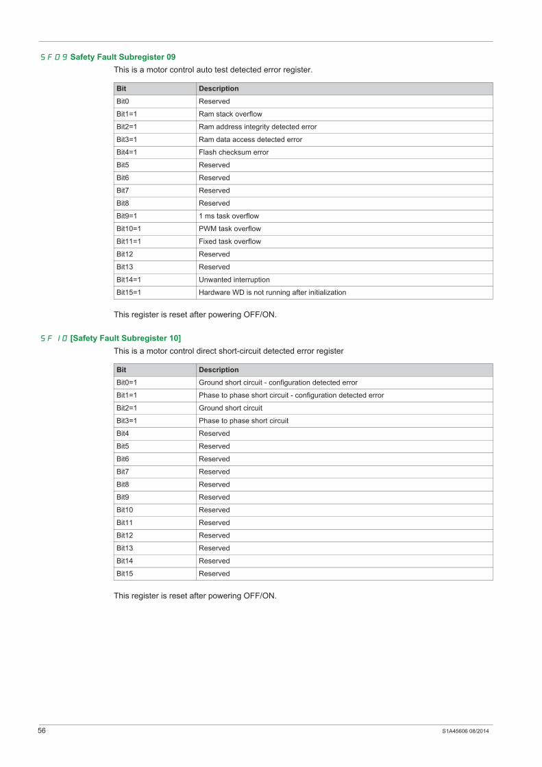
56 S1A45606 08/2014
SF09 Safety Fault Subregister 09
This is a motor control auto test detected error register.
This register is reset after powering OFF/ON.
SF10 [Safety Fault Subregister 10]
This is a motor control direct short-circuit detected error register
This register is reset after powering OFF/ON.
Bit Description
Bit0 Reserved
Bit1=1 Ram stack overflow
Bit2=1 Ram address integrity detected error
Bit3=1 Ram data access detected error
Bit4=1 Flash checksum error
Bit5 Reserved
Bit6 Reserved
Bit7 Reserved
Bit8 Reserved
Bit9=1 1 ms task overflow
Bit10=1 PWM task overflow
Bit11=1 Fixed task overflow
Bit12 Reserved
Bit13 Reserved
Bit14=1 Unwanted interruption
Bit15=1 Hardware WD is not running after initialization
Bit Description
Bit0=1 Ground short circuit - configuration detected error
Bit1=1 Phase to phase short circuit - configuration detected error
Bit2=1 Ground short circuit
Bit3=1 Phase to phase short circuit
Bit4 Reserved
Bit5 Reserved
Bit6 Reserved
Bit7 Reserved
Bit8 Reserved
Bit9 Reserved
Bit10 Reserved
Bit11 Reserved
Bit12 Reserved
Bit13 Reserved
Bit14 Reserved
Bit15 Reserved

S1A45606 08/2014 57
SF11 [Safety Fault Subregister 11]
This is a motor control dynamic verification of activity detected error register
This register is reset after powering OFF/ON.
Bit Description
Bit0=1 Application requested a diagnostic of direct short-circuit
Bit1=1 Application requested consistency verification of stator frequency estimation (voltage and current)
Bit2=1 Application requested diagnostic of SpdStat provided by motor control
Bit3 Reserved
Bit4 Reserved
Bit5 Reserved
Bit6 Reserved
Bit7 Reserved
Bit8=1 Motor control diagnostic of direct short circuit is enabled
Bit9=1 Motor control consistency verification of stator frequency estimation is enabled
Bit10=1 Motor control diagnostic of SpdStat provided by motor control is enabled
Bit11 Reserved
Bit12 Reserved
Bit13 Reserved
Bit14 Reserved
Bit15 Reserved

58 S1A45606 08/2014

S1A45606 08/2014 57
Technical Data
Chapter 6Technical Data
What Is in This Chapter?
This chapter contains the following topics:
Topic Page
Electrical Data 58
Getting and Operating the Safety Function 59
Safety Function Capability 60
Debounce Time and Response Time 62

58 S1A45606 08/2014
Electrical Data
Logic Type
The drive logic inputs and logic outputs can be wired for logic type 1 or logic type 2.
Safety functions must only be used in source mode.
Signal inputs are protected against reverse polarity, outputs are protected against short-circuits. The inputs
and outputs are galvanically isolated.
Cabling Label
Logic Type Active State
1 The output draws current (Sink)
Current flows to the input
2 The output supply flows from the input current
Current (Source)
S1A45606 08/2014 59
Getting and Operating the Safety Function
Logic Input
General-purpose logic inputs can be used to trigger a safety function. Logic inputs have to be combined in
pairs to obtain a redundant request. There are only 4 general-purpose logic inputs that can be linked to
safety functions (LI3, LI4, LI5, LI6).The pairs of logic inputs are fixed and are:
LI3 and LI4
LI5 and LI6
Another combination is only possible for the STO function: LI3 and STO
Pairs of logic inputs can only be assigned once when they are linked to a safety function. When you set a
safety function on an logic input you cannot set another function (safety or other) on this logic input. If you
set a non-safety function on an logic input you cannot set a safety function on this logic input.
The SISTEMA Software
The SISTEMA software allows machine developers and testers of safety-related machine controls to
evaluate the safety standard or level of their machine in the context of ISO 13849-1. The tool allows you
to model the structure of safety-related control components based on the designated architectures,
allowing automated calculation of the reliability standards with various levels of detail, including that of the
Performance Level (PL).
The Altivar 32 Libraries are available from www.schneider-electric.com.
Preventa Safety Relays
Used for the creation of complex safety functions in machines, allowing management of the I/O, and also
for protecting both the operator and the machine.
The Preventa range of products feature microprocessor-based technology using the redundancy principle,
and are essential to ensure safe operation of dangerous machinery.

60 S1A45606 08/2014
Safety Function Capability
PDS (SR) safety functions are part of an overall system
If the qualitative and quantitative safety objectives determined by the final application require some
adjustments to ensure safe use of the safety functions, the integrator of the BDM (Basic Drive Module) is
responsible for these additional changes (for example, managing the mechanical brake on the motor).
Also, the output data generated by the use of safety functions (fault relay activation, error codes or
information on the display, etc.) is not considered to be safety-related data.
Machine Application Function Configuration
(1) Because the IEC 62061 standard concerns integration, this standard distinguishes the overall safety
function (which is classified SIL2 or SIL3 for ATV32 according to the diagrams Process system SF - Case 1
and Process system SF - Case 2 from components which constitute the safety function (which is classified
SIL2 CL or SIL3 CL for ATV32).
(2) According to table 6 of IEC 62061 (2005).
(3) According to table 4 of EN 13849-1 (2008).
(4) If protection against supply interruption or voltage reduction and subsequent restoration is needed
according to IEC 60204-1, a safety module type Preventa XPS AF or equivalent must be used.
(5) SS1 type C: the power drive initiates the motor deceleration and initiates the STO function after an
application specific time delay.
(6) SS1 type B: the power drive initiates and monitors the motor deceleration rate within set limits to stop
the motor and initiates the STO function when the motor speed is below a specified limit.
Process Application Function Configuration
(1) Because the IEC 62061 standard concerns integration, this standard distinguishes the overall safety
function (which is classified SIL2 or SIL3 for ATV32 according to diagrams CASE 1 and CASE 2 from
components which constitute the safety function (which is classified SIL2 CL or SIL3 CL for ATV32).
(2) SS1 type C: the power drive initiates the motor deceleration and initiates the STO function after an
application specific time delay.
(3) SS1 type B: the power drive initiates and monitors the motor deceleration rate within set limits to stop
the motor and initiates the STO function when the motor speed is below a specified limit.
STO SS1 type C (5) SLS/STO/SS
1 type B (6)
STO STO and LI3 STO with Preventa
XPS ATE or
XPS AV or
equivalent
STO and LI3 with
Preventa
XPS AV or
equivalent
LI3
LI4
LI5
LI6
Sta
nd
ard
IEC 61800-5-2 /
IEC 61508 /
SIL2 SIL3 SIL2 SIL3 SIL2
IEC 62061 (1) SIL2 SIL3 CL SIL2 CL SIL3 CL SIL2 CL
EN 954-1 (2) Category 3 Category 4 Category 3 Category 4 Category 3
ISO 13849-1 (3) Category 3
PL d
Category 4
PL e
Category 3
PL d
Category 4
PL e
Category 3
PL d
IEC 60204-1 (4) Category stop 0 Category stop 0 Category stop 1 Category stop 1
STO SS1 type C (2) SLS / STO / SS1 type B
(3)
STO STO and LI3 STO with Preventa
XPS ATE or XPS AV
or equivalent
STO and LI3
with Preventa
XPS AV or
equivalent
LI3 LI4 LI5 LI6
Sta
nd
ard IEC 61800-5-2
IEC 61508
SIL2 SIL3 SIL2 SIL3 SIL2
IEC 62061 (1) SIL2 CL SIL3 CL SIL2 CL SIL3 CL SIL2 CL
S1A45606 08/2014 61
Input Signal Safety Functions
Summary of the Reliability Study
(1) FIT: Failure In Time = Failure/10-9 hours.
(2) Because the IEC 62061 standard concerns integration, this standard distinguishes the overall safety
function (which is classified SIL2 or SIL3 for ATV32 according to diagrams Process system SF - Case 1
and Process system SF - Case 2, from components which constitute the safety function (which is classified
SIL2 CL or SIL3 CL for ATV32).
(3) According to table 6 of IEC 62061 (2005).
(4) According to table 4 of EN 13849-1 (2008).
Preventive annual activation of the safety function is recommended.
However, the safety levels can be obtained (with lower margins) without annual activation.
For the machine environment, a safety module is required for the STO function.
To avoid the use of a safety module, the Restart function parameters must be part of the safety function.
Please refer to the description of advantages of the safety module.
NOTE: The table above is not sufficient to evaluate the PL of a PDS. The PL evaluation has to be done at
the system level. The fitter or the integrator of the BDM (Basic Drive Module) has to do the system PL
evaluation by including sensors data with numbers from the table above.
Input signals safety functions Units Value for LI3 to LI6 Value for STO
Logic 0 (Ulow) V < 5 < 2
Logic 1 (Uhigh) V > 11 > 17
Impedance (24V) k 3.5 1.5
Debounce time ms < 1 < 1
Response time of safety function ms < 10 < 10
Function Standard Input STO input STO input & LI3 LI3 & LI4 or LI5 & LI6
STO IEC 61508 Ed.2 SFF 96.7% 96% 94.8%
PFD10y 7.26.10-4 4.00.10-4 2.44.10-3
PFD1y 7.18.10-5 3.92.10-5 2.33.10-4
PFHequ_1y 8.20 FIT (1) 4.47 FIT (1) 26.6 FIT (1)
Type B B B
HFT 1 1 0
DC 93.1% 91.5% 90%
SIL capability 2 3 2
IEC 62061 (1) SIL CL capability 2 3 2
EN 954-1 (2) Category 3 4 3
ISO 13849-1 (3) PL d e d
Category 3 4 3
MTTFd in years 13900 L1 3850L2 29300 4290
SS1 type
BSLS
IEC 61508 Ed.2 SFF 93.3%
PFD10y 2.72.10-3
PFHequ_10y 31.1 FIT (1)
Type B
HFT 0
DC 78.7%
SIL capability 2
IEC 62061 (2) SIL CL capability 2
EN 954-1 (3) Category 3
ISO 13849-1 (4) PL d
Category 3
MTTFd in years 3670
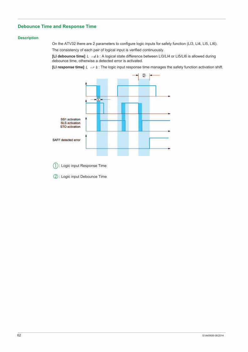
62 S1A45606 08/2014
Debounce Time and Response Time
Description
On the ATV32 there are 2 parameters to configure logic inputs for safety function (LI3, LI4, LI5, LI6).
The consistency of each pair of logical input is verified continuously.
[LI debounce time] LIdt: A logical state difference between LI3/LI4 or LI5/LI6 is allowed during
debounce time, otherwise a detected error is activated.
[LI response time] LIrt: The logic input response time manages the safety function activation shift.
: Logic input Response Time
: Logic input Debounce Time

S1A45606 08/2014 63
Certified Architectures
Chapter 7Certified Architectures
What Is in This Chapter?
This chapter contains the following topics:
Topic Page
Introduction 64
Multi-drive with the Safety Module Type Preventa XPS AF - Case 1 65
Multi-drive with the Safety Module Type Preventa XPS AF - Case 2 66
Multi-drive Without the Safety Module 67
Single Drive with the Safety Module Type Preventa XPS AV - Case 1 68
Single Drive with the Safety Module Type Preventa XPS AV - Case 2 69
Single Drive with the Safety Module Type Preventa XPS AF - Case 1 70
Single Drive with the Safety Module Type Preventa XPS AF - Case 2 71
Single Drive According to IEC 61508 and IEC 60204-1 - Case 1 72
Single Drive According to IEC 61508 and IEC 60204-1 - Case 2 73

64 S1A45606 08/2014
Introduction
Certified Architectures
NOTE: For certification relating to functional aspects, only the PDS(SR) (Power Drive System suitable for
use in safety-related applications) will be considered, not the complete system into which it is integrated to
help to ensure the functional safety of a machine or a system/process.
These are the certified architectures:
Multi-drive with the Safety module type Preventa XPS AF - Case 1
Multi-drive with the Safety module type Preventa XPS AF - Case 2
Multi-drive without the Safety module
Single drive with the Safety module type Preventa XPS AV - Case 1
Single drive with the Safety module type Preventa XPS AV - Case 2
Single drive with the Safety module type Preventa XPS AF - Case 1
Single drive with the Safety module type Preventa XPS AF - Case 2
Single drive according to IEC 61508 and IEC 60204-1 - Case 1
Single drive according to IEC 61508 and IEC 60204-1 - Case 2
The safety functions of a PDS(SR) (Power Drive System suitable for use in safety-related applications) are
part of an overall system.
If the qualitative and quantitative safety-related objectives determined by the final application require some
adjustments to ensure safe use of the safety functions, the integrator of the BDM (Basic Drive Module) is
responsible for these additional changes (for example, managing the mechanical brake on the motor).
Also, the output data generated by the use of safety functions (fault relay activation, error codes or
information on the display, etc.) is not considered to be a safety-related data.

S1A45606 08/2014 65
Multi-drive with the Safety Module Type Preventa XPS AF - Case 1
Multi-drive with the Safety Module Type Preventa XPS AF According to EN 954-1, ISO 13849-1 and IEC 60204-1
(Machine)
The following configurations apply to the diagram:
STO category 4, PL e/SIL3 Machine with Safety module type Preventa XPS AF or equivalent and LI3
set to STO
SLS category 3, PL d/SIL2 or SS1 type B category 3 on LI5/LI6
Or
STO category 4, PL e/SIL3 Machine with Safety module type Preventa XPS AF or equivalent and LI3
set to STO
LI4 and LI5/LI6 not set to a safety function
(1) Braking resistor, if used, (2) Standardized coaxial cable, type RG174/U according to MIL-C17 or KX3B
according to NF C 93-550, external diameter 2.54 mm /0.09 in., maximum length 15 m / 49.21 ft. The cable
shielding must be earthed, (3) Line choke, if used, (4) Multi-drives is possible with another drive (Example:
ATV71 with PWR connection or Lexium servo drives)
NOTE: For more information about the control terminal characteristics, please refer to the installation
manual.

66 S1A45606 08/2014
Multi-drive with the Safety Module Type Preventa XPS AF - Case 2
Multi-drive with the Safety Module Type Preventa XPS AF According to EN 954-1, ISO 13849-1 and IEC 60204-1
(Machine)
The following configurations apply to the diagram below:
STO category 3, PL d/SIL2 Machine with Safety module type Preventa XPS AF or equivalent
SLS category 3, PL d/SIL2 or SS1 type B category 3 on LI3/LI4 or LI5/LI6
(1) Braking resistor, if used, (2) Standardized coaxial cable, type RG174/U according to MIL-C17 or KX3B
according to NF C 93-550, external diameter 2.54 mm /0.09 in., maximum length 15 m / 49.21 ft. The cable
shielding must be earthed, (3) Line choke, if used, (4) Multi-drives is possible with another drive (Example:
ATV71 with PWR connection or Lexium servo drives).
NOTE: For more information about the control terminal characteristics, please refer to the installation
manual.
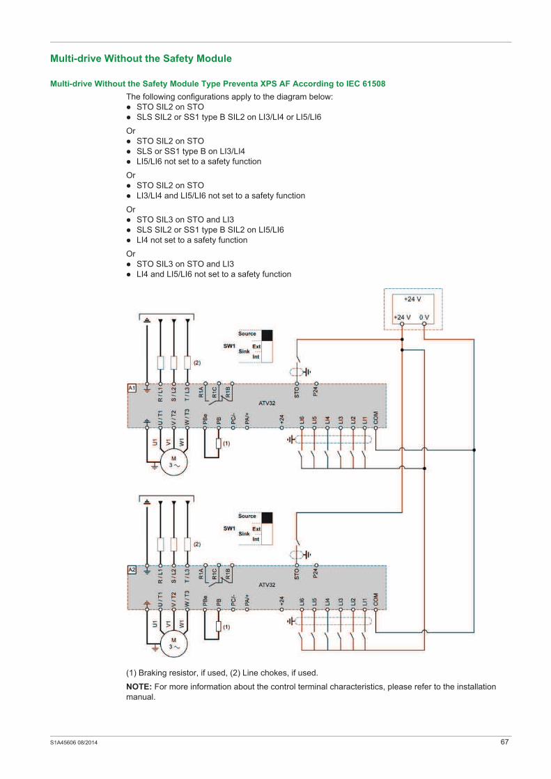
S1A45606 08/2014 67
Multi-drive Without the Safety Module
Multi-drive Without the Safety Module Type Preventa XPS AF According to IEC 61508
The following configurations apply to the diagram below:
STO SIL2 on STO
SLS SIL2 or SS1 type B SIL2 on LI3/LI4 or LI5/LI6
Or
STO SIL2 on STO
SLS or SS1 type B on LI3/LI4
LI5/LI6 not set to a safety function
Or
STO SIL2 on STO
LI3/LI4 and LI5/LI6 not set to a safety function
Or
STO SIL3 on STO and LI3
SLS SIL2 or SS1 type B SIL2 on LI5/LI6
LI4 not set to a safety function
Or
STO SIL3 on STO and LI3
LI4 and LI5/LI6 not set to a safety function
(1) Braking resistor, if used, (2) Line chokes, if used.
NOTE: For more information about the control terminal characteristics, please refer to the installation
manual.
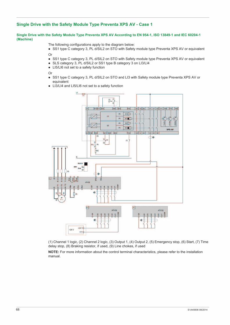
68 S1A45606 08/2014
Single Drive with the Safety Module Type Preventa XPS AV - Case 1
Single Drive with the Safety Module Type Preventa XPS AV According to EN 954-1, ISO 13849-1 and IEC 60204-1
(Machine)
The following configurations apply to the diagram below:
SS1 type C category 3, PL d/SIL2 on STO with Safety module type Preventa XPS AV or equivalent
Or
SS1 type C category 3, PL d/SIL2 on STO with Safety module type Preventa XPS AV or equivalent
SLS category 3, PL d/SIL2 or SS1 type B category 3 on LI3/LI4
LI5/LI6 not set to a safety function
Or
SS1 type C category 3, PL d/SIL2 on STO and LI3 with Safety module type Preventa XPS AV or
equivalent
LI3/LI4 and LI5/LI6 not set to a safety function
(1) Channel 1 logic, (2) Channel 2 logic, (3) Output 1, (4) Output 2, (5) Emergency stop, (6) Start, (7) Time
delay stop, (8) Braking resistor, if used, (9) Line chokes, if used
NOTE: For more information about the control terminal characteristics, please refer to the installation
manual.

S1A45606 08/2014 69
Single Drive with the Safety Module Type Preventa XPS AV - Case 2
Single Drive with the Safety Module Type Preventa XPS AV According to EN 954-1, ISO 13849-1 and IEC 60204-1
(Machine)
The following configurations apply to the diagram below:
SS1 type C category 4, PL e/SIL3 on STO and LI3 with Safety module type Preventa XPS AV or
equivalent
SLS category 3, PL d/SIL2 or SS1 type B category 3 PL d/SIL2 on LI5/LI6
LI4 not set to a safety function
(1) Channel 1 logic, (2) Channel 2 logic, (3) Output 1, (4) Output 2, (5) Emergency stop, (6) Time delay
stop, (7) Braking resistor, if used, (8) Line chokes, if used.
NOTE: For more information about the control terminal characteristics, please refer to the installation
manual.

70 S1A45606 08/2014
Single Drive with the Safety Module Type Preventa XPS AF - Case 1
Single Drive with the Safety Module Type Preventa XPS AF According to EN 954-1, ISO 13849-1, IEC 62061 and 60204-
1 (Machine)
The following configurations apply to the diagram below:
STO category 3, PL d/SIL2 on STO with Safety module type Preventa XPS AF or equivalent
SLS category 3, PL d/SIL2 or SS1 type B category 3 on LI3/LI4 or LI5/LI6
Or
STO category 3, PL d/SIL2 on STO with Safety module type Preventa XPS AF or equivalent
SLS category 3, PL d/SIL2 or SS1 type B category 3 on LI3/LI4
LI5/LI6 not set to a safety function
Or
STO category 3, PL d/SIL2 on STO with Safety module type Preventa XPS AF or equivalent
LI3/LI4 and LI5/LI6 not set to a safety function
(1) Braking resistor, if used, (2) Line chokes, if used.
NOTE: For more information about the control terminal characteristics, please refer to the installation
manual.

S1A45606 08/2014 71
Single Drive with the Safety Module Type Preventa XPS AF - Case 2
Single Drive with the Safety Module Type Preventa XPS AF According to EN 954-1, ISO 13849-1, IEC 62061 and 60204-
1 (Machine)
The following configurations apply to the diagram below:
STO category 4, PL e/SIL3 on STO with Safety module type Preventa XPS AF or equivalent and LI3
set to STO
SLS category 3, PL d/SIL2 or SS1 type B category 3 on LI5/LI6
LI4 not set to a safety function
(1) Start, (2) Braking resistor, if used, (3) Line chokes if used.
NOTE: For more information about the control terminal characteristics, please refer to the installation
manual.

72 S1A45606 08/2014
Single Drive According to IEC 61508 and IEC 60204-1 - Case 1
Single Drive According to IEC 61508 and IEC 60204-1 Without Protection Against Supply Interruption or Voltage
Reduction and Subsequent Rotation
The following configurations apply to the diagram below:
STO SIL2 on STO
STO or SLS SIL2 or SS1 type B SIL2 on LI3/LI4 or LI5/LI6
Or
STO SIL2 on STO
STO or SLS or SS1 type B on LI3/LI4
LI5/LI6 not set to a safety function
Or
STO SIL2 on STO
LI3/LI4 and LI5/LI6 not set to a safety function
Or
STO SIL3 on STO and LI3
SLS SIL2 or SS1 type B SIL2 on LI5/LI6
LI4 not set to a safety function
Or
STO SIL3 on STO and LI3
LI4 and LI5/LI6 not set to a safety function
(1) Braking resistor, if used, (2) Line chokes if used.
NOTE: For more information about the control terminal characteristics, please refer to the installation
manual.
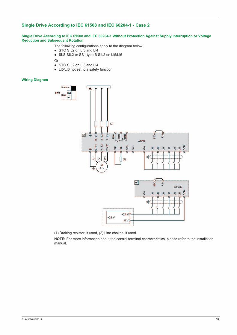
S1A45606 08/2014 73
Single Drive According to IEC 61508 and IEC 60204-1 - Case 2
Single Drive According to IEC 61508 and IEC 60204-1 Without Protection Against Supply Interruption or Voltage
Reduction and Subsequent Rotation
The following configurations apply to the diagram below:
STO SIL2 on LI3 and LI4
SLS SIL2 or SS1 type B SIL2 on LI5/LI6
Or
STO SIL2 on LI3 and LI4
LI5/LI6 not set to a safety function
Wiring Diagram
(1) Braking resistor, if used, (2) Line chokes, if used.
NOTE: For more information about the control terminal characteristics, please refer to the installation
manual.

74 S1A45606 08/2014

S1A45606 08/2014 75
Commissioning
Chapter 8Commissioning
What Is in This Chapter?
This chapter contains the following topics:
Topic Page
Safety Functions Tab 76
Configure Safety Functions Panel 77
Visualization and Status of Safety Functions 81
Copying Safety Related Configuration from Device to PC and from PC to Device 82
Machine Signature 85

76 S1A45606 08/2014
Safety Functions Tab
Introduction
To access the safety function configuration, click the Safety Functions tab. This screen is read-only,
allowing you to see all current safety function configurations.
The Safety Functions tab provides access to:
an outline of the safety function features available on the ATV32 (accessible online/offline)
the status of all I/O in connected mode
general information about the machine (online/offline).
It also provides access to the following dialog boxes:
Configuration
Configure (only available in connected mode)
Reset Configuration
Copy from DEVICE to PC
Copy from PC to DEVICE
Password Configuration
Modify Password
Reset Password
Steps to Configure the Safety Functions
Once connected:
If... Then ...
you are not in online mode In the menu bar, click Communication Connect to Device or click the
Connect to Device icon
you are online mode Click the Configure button in the Safety Functions tab.
Step Action Comment
1 Click the Configure button in the
Safety Functions tab.
A Define Configuration Password dialog box appears:
Type the new configuration password in Enter New
Password box
Retype the new configuration password in Confirm New
Password box.
Click Ok
NOTE:
Your password:
Should have only numeric value, choose the value
between 1...9999.
Should not exceed more than 4 digits.
Should not have the value 0.
Result: Opens the Configuration of Safety Functions
window.
If... Then ...
you have already defined
the password
type your safety function configuration password in Enter Configuration
Password box, click Ok.
Result: Opens the Configuration of Safety Functions window.

S1A45606 08/2014 77
Configure Safety Functions Panel
Overview
The Configuration of Safety Functions panel includes the Information, STO, SLS, SS1 and
Input/Output tabs.
Information Tab
The information tab allows you to define and display product system information
Information filled in automatically by SoMove:
Date (format depends on the PC local and linguistic options)
Device Type
Drive Reference
Information filled in manually:
Device Serial No (number)
Machine Name
Company Name
End-User Name
Comments
Safe Torque Off (STO) Tab
For more information about STO function, see STO description (see page 18).
For this function, only the associated set of inputs should be selected in the box. The parameter to be
managed is: STOA.
Code Name/Description Factory
Setting
StO [Safe Torque Off]
StOA [STO function activation] [No]
nO
L34
L56
L3PW
[No: Not assigned]
[LI3 and LI4]: logic input 3/4 low state
[LI5 and LI6]: logic input 5/6 low state
[LI3 and STO]: logic input 3/STO low state
This parameter is used to configure the channel used to trigger the STO function. If you set STOA=No,
STO function is always active but just on STO input

78 S1A45606 08/2014
Safely Limited Speed (SLS) Tab
For more information about SLS function, see SLS description (see page 22).
Code Name/Description Adj. Range Factory
Setting
SLS [Safely-Limited Speed]
SLSA
nO
L34
L56
[SLS function activation] [No]
[No]: Not assigned
[LI3 and LI4]: logic input 3/4 low state
[LI5 and LI6]: logic input 5/6 low state
This parameter is used to configure the channel used to trigger the SLS function.
SLt [Safely Limited speed Type Element] [Type1]
tYp1
tYp2
tYp3
tYp4
This parameter is used to select the SLS type.
[Type1] : SLS type 1
[Type2] : SLS type 2
[Type3] : SLS type 3
[Type4]: SLS type 4
Refer to function description to have information about behavior of different type.
SLSP [SLS set point] parameter 0...599 Hz 0
This parameter is only visible if SLT = Type2 or SLT = Type3 or SLT = Type 4
SLSP is used to set the maximum speed
SLtt [SLS tolerance threshold] parameter 0...599 Hz 0
The behavior of this parameter depends on the value of SLT, see above
SLwt [SLS Wait Time] parameter 0...5000 ms 0
This parameter is used to set the maximum time for StFr to be greater than SSSL.
When SLwt is reached, STO function is triggered.
Unit of this parameter is 1 ms.
For example
If the value is set to 2000 units, then the SLS wait time in second is:
2000*1 ms = 2 s
This parameter can be modified only if SLT = Type 2 or SLT = Type 3
For SLS type 1 and SLS type 4, SLwt is always set to 0
SSrt [SS1 ramp value] parameter 1 to 5990 1
The unit depends on the SSRU parameter. Use this parameter to set the value of the SS1 deceleration
ramp.
SS1 ramp = SSRT*SSRU example: If SSRT = 250 and SSRU = 1 Hz/s then the deceleration ramp = 25
Hz/s.
This parameter is similar to the SS1 safety function, for more information see SS1 (see page 35).
SSrU
1H
10H
100H
[SS1 ramp unit] parameter [1 Hz/s]
[1 Hz/s]
[10 Hz/s]
[100 Hz/s]
This parameter is used to set the SSrt unit.
This parameter is similar to the SS1 safety function configured, for more information see SS1
(see page 35).
SStt [SS1 trip threshold] 0...599 Hz 0
This parameter sets the tolerance zone around the deceleration ramp in which the frequency may vary.
This parameter is similar to the SS1 safety function configured in another tab.
SSSL [SLS/SS1 standstill level] parameter 0...599 Hz 0
This parameter adjusts the frequency at which the drive should go into STO state at the end of the SS1
ramp.
This parameter is similar to the SS1 safety function configured in another tab.
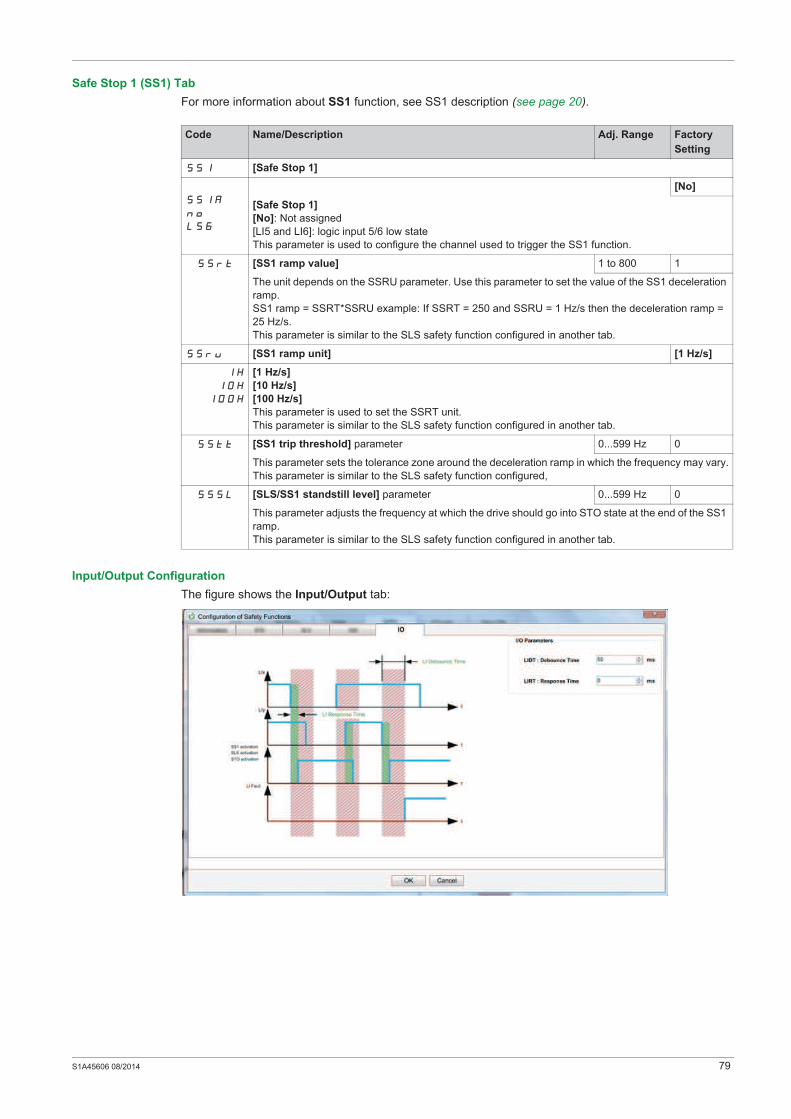
S1A45606 08/2014 79
Safe Stop 1 (SS1) Tab
For more information about SS1 function, see SS1 description (see page 20).
Input/Output Configuration
The figure shows the Input/Output tab:
Code Name/Description Adj. Range Factory
Setting
SS1 [Safe Stop 1]
SS1A
nO
L56
[No]
[Safe Stop 1]
[No]: Not assigned
[LI5 and LI6]: logic input 5/6 low state
This parameter is used to configure the channel used to trigger the SS1 function.
SSrt [SS1 ramp value] 1 to 800 1
The unit depends on the SSRU parameter. Use this parameter to set the value of the SS1 deceleration
ramp.
SS1 ramp = SSRT*SSRU example: If SSRT = 250 and SSRU = 1 Hz/s then the deceleration ramp =
25 Hz/s.
This parameter is similar to the SLS safety function configured in another tab.
SSrU [SS1 ramp unit] [1 Hz/s]
1H
10H
100H
[1 Hz/s]
[10 Hz/s]
[100 Hz/s]
This parameter is used to set the SSRT unit.
This parameter is similar to the SLS safety function configured in another tab.
SStt [SS1 trip threshold] parameter 0...599 Hz 0
This parameter sets the tolerance zone around the deceleration ramp in which the frequency may vary.
This parameter is similar to the SLS safety function configured,
SSSL [SLS/SS1 standstill level] parameter 0...599 Hz 0
This parameter adjusts the frequency at which the drive should go into STO state at the end of the SS1
ramp.
This parameter is similar to the SLS safety function configured in another tab.

80 S1A45606 08/2014
Password Configuration - Modify Password
This function allows you to modify the configuration password in the drive.
To modify the configuration password
Password Configuration - Reset Password
If you cannot remember the configuration password defined in the drive, you need to know the universal
password to reset the drive. To obtain this password, contact your Schneider Electric contact.
After this operation, the device reverts to no defined configuration password and the session is
automatically closed.
However, the function configuration remains unchanged.
Reset Configuration
This function is used to reset the configuration of the safety function to the factory settings.
To access the function, click the Reset Configuration button in the Safety Functions tab.
First enter the password, then confirm your choice.
After this action, all safety-related parameters are set to factory settings.
Code Name/Description Adj. Range Factory
Setting
IO [Input/Output]
LIdt [LI debounce time] 0...2000 ms 50
In most cases, the 2 logic inputs in a pair used for a safety function (LI3-LI4 or LI5-LI6 or STO-LI3) will
not be 100% synchronized. They will not change state at the same time. There is a small delta between
the 2 logic input transitions.
LIdt is the parameter used to set this delta. If the 2 logic inputs change state with a delta lasting less
than LIdt it is considered to be simultaneous transition of the logic inputs. If the delta lasts longer
than LIdt, the drive considers the logic Inputs are no longer synchronized and detected error is
triggered.
LIrt [LI response time] 0...50 ms 0
This parameter is used to filter short impulses on the logic input (only for LI3-LI4 or LI5-LI6, STO not
concerned). Some applications send short impulses on the line to test it. This parameter is used to filter
these short impulses. Commands are only taken into account if the duration is longer than LIrt.
If the duration is shorter the drive considers that there is no command: the command is filtered.
Step Action
1 In Safety Functions tab, click the Modify Password button
Result: opens the Modify Configuration Password dialog box.
2 In the Modify Configuration Password dialog box:
Type the existing configuration password in Enter Current Password box
Type the new configuration password in Enter New Password box
Retype the new configuration password in Confirm New Password box
Click Ok
NOTE: The password typed in Enter New Password box and Confirm New Password box should be
same.
NOTE:
Your password:
Should contain only numeric value, choose the value between 1...9999.
Should not exceed more than 4 digits.
Should not have the value 0.
Result: modifies the configuration password.

S1A45606 08/2014 81
Visualization and Status of Safety Functions
Code Name/Description
SAF- [MONIT. SAFETY] menu - Visible on SoMove and keypad
StFr [Stator Frequency]
Displays the estimated stator frequency in Hz
StOS [STO status]
Status of the Safe Torque Off safety function
IdLE
StO
FLt
[IdLE]: STO not in progress
[Safe torque off]: STO in progress
[Fault]: STO in detected error
SLSS [SLS status]
Status of the Safely limited speed safety function
nO
IdLE
SSI
StO
FLt
WAIt
Strt
[Not config]: SLS not configured
[IdLE]: SLS not in progress
[Safe stop 1]: SLS ramp in progress
[Safe torque off]: SLS safe torque off request in progress
[Fault]: SLS in detected error
[wAIT]: SLS waiting for activation
[Started]: SLS in transient state
SS1S [SS1 status]
Status of the Safe Stop 1 safety function
nO
IdLE
SSI
StO
FLt
[Not config]: SS1 not configured
[IdLE]: SS1 not in progress
[Safe stop 1]: SS1 ramp in progress
[Safe torque off]: SS1 safe torque off request in progress
[Fault]: SS1 in detected error
SAF- [MONIT. SAFETY] menu - Visible ONLY on SoMove
SFtY [Safety drive status]
Safety function status of the drive
IStd
SAFE
[Standard drive]: Standard product without safety function configured
[Safety drive]: product with at least 1 safety function configured

82 S1A45606 08/2014
Copying Safety Related Configuration from Device to PC and from PC to Device
Overview
This feature is used to copy/paste the tested safety-related configuration in several ATV32 drives.
This feature allows you to:
identify unique safety-related configuration on the drive
copy the safety-related configuration file from ATV32 drive to PC.
copy the safety-related configuration file from PC to ATV32 drives
Architecture
The figure shows the architecture for copying the safety-related configuration from device to PC and PC to
device:
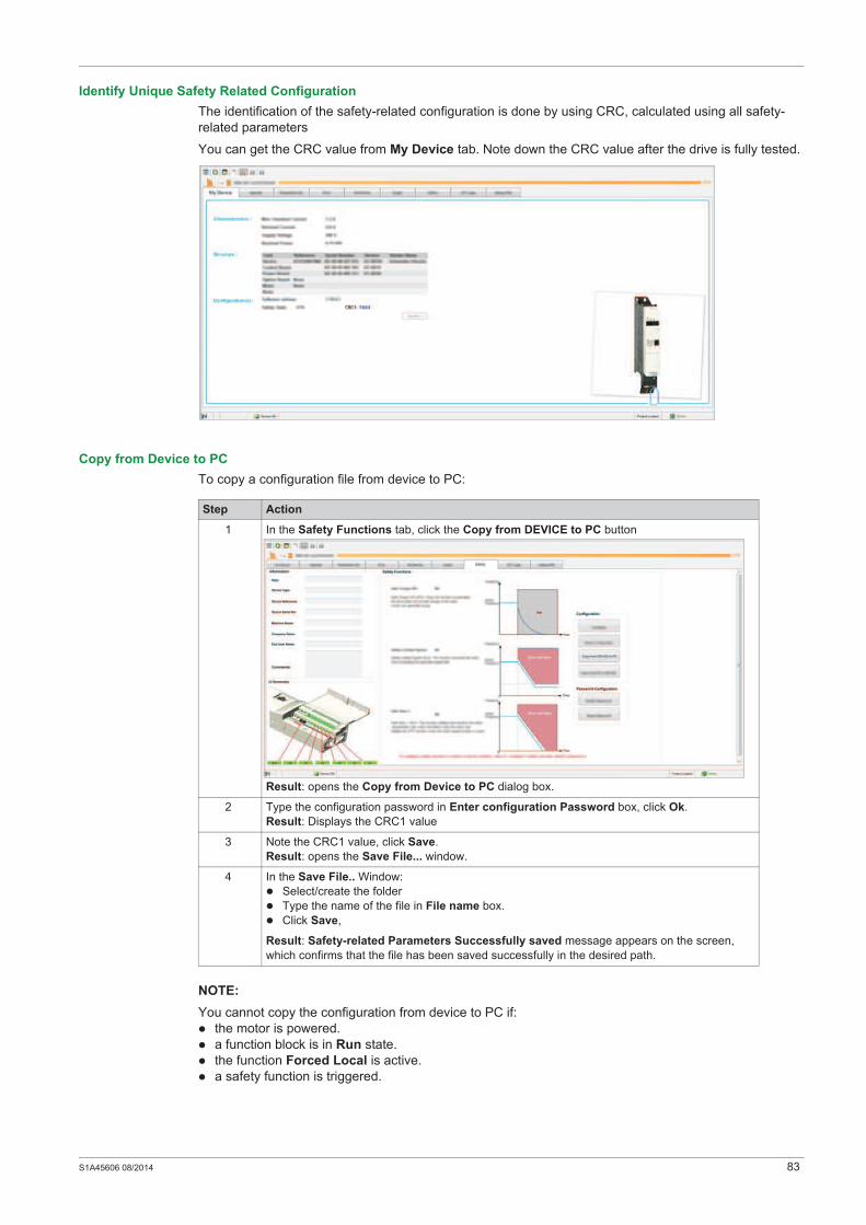
S1A45606 08/2014 83
Identify Unique Safety Related Configuration
The identification of the safety-related configuration is done by using CRC, calculated using all safety-
related parameters
You can get the CRC value from My Device tab. Note down the CRC value after the drive is fully tested.
Copy from Device to PC
To copy a configuration file from device to PC:
NOTE:
You cannot copy the configuration from device to PC if:
the motor is powered.
a function block is in Run state.
the function Forced Local is active.
a safety function is triggered.
Step Action
1 In the Safety Functions tab, click the Copy from DEVICE to PC button
Result: opens the Copy from Device to PC dialog box.
2 Type the configuration password in Enter configuration Password box, click Ok.
Result: Displays the CRC1 value
3 Note the CRC1 value, click Save.
Result: opens the Save File... window.
4 In the Save File.. Window:
Select/create the folder
Type the name of the file in File name box.
Click Save,
Result: Safety-related Parameters Successfully saved message appears on the screen,
which confirms that the file has been saved successfully in the desired path.

84 S1A45606 08/2014
Copy from PC to Device
To copy a file from PC to device:
NOTE:
You cannot copy the cofiguration from PC to device if:
the motor is powered.
a function block is in Run state.
the function Forced Local is active.
the configuration of the safety function is already present in the device
WARNINGUNEXPECTED EQUIPMENT OPERATION
Connect the PC using point-to-point connection.
Copy from PC to Device operation should be performed only by qualified IEC61800-5-2 personnel
Test the safety function configuration after copying the configuration from PC to device.
Failure to follow these instructions can result in death, serious injury, or equipment damage.
Step Action
1 In the Safety Functions tab, click the Copy from PC to DEVICE button
Result: Warning box appears, read the following instruction before proceeding with copy from
PC to device operation.
2
Click Ok
Result: Opens the Open File... window.
3 In the Open File... Window
Select .sfty file.
Click Open
Result: Displays the CRC1 value
4 Verify whether the CRC1 value is same as the CRC1 value noted while copying the configuration
from device to PC if both CRC1 values are same then click Continue.
Result: Opens the Copy from PC to Device dialog box.
5 Type the password (49157) in the Enter copy password box, click Ok.
Result: Configuration is successfully copied from PC to device. A commisoning test must be
done on the safety function.

S1A45606 08/2014 85
Machine Signature
Overview
The purpose of the test is to verify proper configuration of the defined safety functions and test mechanisms
and to examine the response of dedicated monitoring functions to explicit input of values outside the
tolerance limits.
The test must cover all drive-specific Safety configured monitoring functions and global Safety integrated
functionality in ATV32.
Condition Prior to Acceptance Test
The machine is wired up correctly.
All safety-related devices such as protective door monitoring devices, light barriers, and emergency
stop switches are connected and ready for operation.
All motor parameters and command parameters must be correctly set on the drive.
Acceptance Test Process
The acceptance test is configured with SoMove software.
Step Action Comment
1 Select the Device Safety Function Machine
Signature menu and follow the five steps below
2 General Information
To add this step to the final report select Add to the
machine signature
Click Next.
The information displayed here corresponds to the
Identification section in the Safety Functions tab.
3 Function Summary
To add a function to the final report select Add to the
machine signature
Click Next
This step is composed of sub-steps.
Each sub-step relates to one of the following safety
functions:
STO
SLS
SS1
In a function, sub-step the function diagram and
parameters values are displayed.
A text box allows you to enter additional text in this
step.
4 I/O Summary
To add a function to the final report select Add to the
machine signature
Click Next
The information displayed here corresponds to the
Logic Input summary folder of the Safety
Functions tab:
The logic input that is assigned to a safety
function are displayed in red and show the related
safety function
The logic input that is not assigned to a safety
function do not show any assignment and are
displayed in green
5 Test
To add a function to the final report select Add to the
machine signature
Click Next
In this step, you tick the box when you have tested
the safety functions to confirm that you have verified
the correct behavior of the functions for all devices.
6 Key
Click Finish to create the report
The checksum of the safety-related configuration is
displayed as it is calculated for transmission to the
connected device when you click Apply.
This allows you to compare the checksum value with
the one displayed in the identification menu on the
graphic display terminal
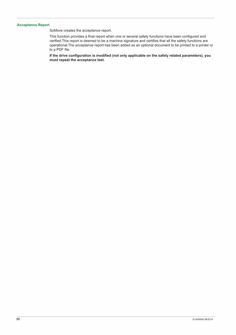
86 S1A45606 08/2014
Acceptance Report
SoMove creates the acceptance report.
This function provides a final report when one or several safety functions have been configured and
verified.This report is deemed to be a machine signature and certifies that all the safety functions are
operational.The acceptance report has been added as an optional document to be printed to a printer or
to a PDF file.
If the drive configuration is modified (not only applicable on the safety related parameters), you
must repeat the acceptance test.
S1A45606 08/2014 89
Services and Maintenance
Chapter 9Services and Maintenance
What Is in This Chapter?
This chapter contains the following topics:
Topic Page
Maintenance 90
Power and MCU Replacement 91
Changing Machine Equipment 92
90 S1A45606 08/2014
Maintenance
Overview
By way of preventive maintenance, the Safety functions must be activated at least once a year. The drive
power supply must be turned off and then on again before carrying out this preventive maintenance. The
drive logic output signals cannot be considered to be safety-related signals. Install interference
suppressors on all inductive circuits near the drive or coupled to the same circuit (relays, contactors,
solenoid, valves, etc.).
NOTE: For more product information, see the installation manual and programming manual on
www.schneider-electric.com.
S1A45606 08/2014 91
Power and MCU Replacement
Overview
You can replace the MCU (Motor Control Unit) part (APP + HMI card) and the power part.
Depending on the drive configuration (safety function active or not), the drive response will differ.
If you replace the power and you keep your MCU, you won’t lose the configuration of the safety functions
but you need to repeat the Acceptance Test to avoid incorrect wiring or incorrect behavior of the safety
function.
If you replace the MCU you will lose your safety-related configuration. You need to reinstall your
Configuration on the new MCU and then repeat the Acceptance Test.
NOTE: For more product information, see the installation manual and programming manual
www.schneider-electric.com.

92 S1A45606 08/2014
Changing Machine Equipment
Overview
If you need to change any part of the drive system (Motor, Emergency stop, etc.) you must repeat the
Acceptance Test.
NOTE: For more product information, see the installation manual and programming manual
www.schneider-electric.com.