aging of turbine drives for safety-related pumps in
TRANSCRIPT

NUREG/CR-5857 ORNL-6713
Aging of Turbine Drives for Safety-Related Pumps in Nuclear Power Plants
Manuscript Completed: March Date Published: June 1995
Prepared by D. F. Cox
Oak Ridge National Laboratory Managed by Martin Marietta Energy Systems, Inc.
Oak Ridge National Laboratory Oak Ridge, TN 37831-6285
Prepared for Division of Engineering Technology^ Office of Nuclear Regulatory Research U.S. Nuclear Regulatory Commission Washington, DC 20555-0001 NRC Job Code B0828
DISTRIBUTION OF THIS D © G U » T IS UNUMTTED


DISCLAIMER
This report was prepared as an account of work sponsored by an agency of the United States Government. Neither the United States Government nor any agency thereof, nor any of their employees, make any warranty, express or implied, or assumes any legal liability or responsibility for the accuracy, completeness, or usefulness of any information, apparatus, product, or process disclosed, or represents that its use would not infringe privately owned rights. Reference herein to any specific commercial product, process, or service by trade name, trademark, manufacturer, or otherwise does not necessarily constitute or imply its endorsement, recommendation, or favoring by the United States Government or any agency thereof. The views and opinions of authors expressed herein do not necessarily state or reflect those of the United States Government or any agency thereof.

DISCLAIMER
Portions of this document may be illegible in electronic image products. Images are produced from the best available original document.

Abstract
This study was performed to examine the relationship between time-dependent degradation and current industry practices in the areas of maintenance, surveillance, and operation of steam turbine drives for safety-related pumps. These pumps are located in the Auxiliary Feedwater (AFW) system for pressurized-water reactor plants and in the Reactor Core Isolation Cooling and High-Pressure Coolant Injection systems for boiling-water reactor plants. This research has been conducted by examination of failure data in the Nuclear Plant Reliability Data System, review of Licensee Event Reports, discussion of problems with operating plant personnel, and personal observation. The reported failure data were reviewed to detennine the cause of the event and the method of discovery. Based on the research results, attempts have been made to determine the predictability of failures and possible preventive measures that may be implemented.
Findings in a recent study of AFW systems indicate that the turbine drive is the single largest contributor to AFW system degradation. However, examination of the data shows that the turbine itself is a reliable piece of equipment with a good service record. Most of the problems documented are the result of problems with the turbine controls and the mechanical overspeed trip mechanism; these apparently stem from three major causes:
1. Originally designed as a continuous drive mechanism with a slow startup sequence, the safety-related turbines are used in standby service with normal startup in ~30 s. The turbines are typically only run from once a month to once a quarter during pump testing. The data indicate that this lack of operation can actually be a major contributor to turbine degradation. Moisture trapped inside the turbine and controls can cause damaging corrosion to the governor and the governor valve.
2. Historically, maintenance practices have resulted in corrective maintenance being performed instead of preventive/predictive maintenance.
3. Design changes by the manufacturer have been implemented with varying degrees of success because of the change in service requirements from the original design requirements.
Recent improvements in maintenance practices and procedures, combined with a stabilization of the design, have led to improved performance resulting in a reliable safety-related component However, these improvements have not been universally implemented.
i i i NUREG/CR-5857


Contents
Page
Abstract iii List of Figures vii
List of Tables ix Executive Summary xi Acknowledgments xiii
Abbreviations xv 1 Introduction 1
1.1 Background 1 1.2 Objective 1 1.3 Scope 1
2 Description of Application 3
2.1 Auxiliary Feedwater System 3 2.2 Reactor Core Isolation Cooling System 4 2.3 High-Pressure Coolant Injection System 5
3 Equipment Description 7 3.1 AFW/RCIC Turbine Description-Operation Overview and Component Function Summary 7
3.1.1 Steam Admission Valve 8 3.1.1.1 Opening Rate 8 3.1.1.2 Valve Type 9 3.1.1.3 Water Slugs „ 9
3.12 T/T Valve 10 3.1.3 Governor Valve 11 3.1.4 Turbine 11 3.1.5 Governor 12 3.1.6 Overspeed Trip Mechanism 12
3.2 HPCI Turbine—Operation Overview 14
3.2.1 Steam Admission Valve 15 3.2.2 Stop Valve 15 3.2.3 Governor Valve 15 3.2.4 Turbine 15 3.2.5 Governor 15 3.2.6 Overspeed Trip Mechanism 17
4 Analysis of Operational Data 19 4.1 Introduction 19 4.2 Data Analysis 19
4.2.1 Failure Data Analysis by Component Group 19 4.2.2 Melhod of Detection 20
4.2.2.1 Programmatic Testing Failures 20 4.2.2.2 Demand Failures 21
4.2.3 Plant Age at Failure 21 4.2.4 Plant Distribution 21
v NUREG/CR-5857

4.2.5 Failure Data Analysis by Year 24 4.2.5.1 Failures by Component and Year 24 4.2.5.2 Failures by Method of Detection and Year 24
4.3 Equipment-Specific Results 24 4.3.1 Steam Admission Valve 24 4.3.2 Turbine 25 4.3.3 Governor Valve 26 4.3.4 Governor Malfunctions 28
4.3.4.1 Contaminated Oil 30 4.3.4.2 Water Contamination 30 4.3.4.3 Particulate Contaminants 30 4.3.4.4 Maladjustment/Set Point Drift 30 4.3.4.5 Miscellaneous Damage 30
4.3.5 OSTMechanism 30 4.3.6 T/T Valve 31
5 Testing 33 5.1 Background 33 5.2 Current Requirements 33 5.3 Failure Detection 34 5.4 Test Methodology Deficiencies • 34 5.5 Vendor Recommendations 34
6 Summary and Conclusions 37
References 39 Appendix A—Governor Configurations 41
NUREG/CR-5857

List of Figures
Figure Page
2.1 Typical AFW system 3 2.2 Typical RCIC system 4 2.3 Typical HPCI system 5 3.1 Major components of turbine system 7 3.2 Ideal flow through SAV 9 3.3 Percentage of full flow vs disk travel for typical gate valve 9 3.4 T/T valve internals 10 3.5 2 1/2-in. governor valve 11 3.6 3-in. governor valve 11 3.7 Basic turbine configuration 12 3.8 Electronic governor remote (EGR) schematic 13 3.9 Mechanical OST mechanism 14 3.10 HPCI stop valve 16 3.11 Multiport HPCI governor valve 17 3.12 HPCI trip valve assembly 18 4.1 Percentage of total failures by component 19 4.2 Failure by method of detection 20 4.3 Failures discovered programatically 21 4.4 Demand failures per year 22 4.5 Percentage of demand failures by year 22 4.6 Normalized turbine age at failure 23 4.7 Cumulative failure count for turbines involved in study 23 4.8 Failures per component per year 24 4.9 Number of failures per year by method of discovery 25 4.10 Breakdown of turbine failures 26 4.11 Breakdown of governor valve failures 27 4.12 Predominant governor subcomponent failures 29 4.13 Predominant governor failure causes 29 A.1 Mechanical governor schematic 43 A.2 EG stability adjustment 45 A.3 EG stability adjustment 46
vii NUREG/CR-5857


List of Tables
Table Page
4.1 Summary of failures by component and year 25 4.2 Summary of failures by method of detection 26 4.3 Breakdown of reported turbine failures 27 4.4 Breakdown of reported governor valve failures 28 4.5 Predominant governor failure causes 30 4.6 OST mechanism failures 31
ix NUREG/CR-5857


Executive Summary
Steam turbine drives for safety-related pumps are used at most commercial nuclear power plants in the United States. Turbine-driven pumps are used in pressurized-water reactors in the Auxiliary Feedwater (AFW) system to provide diversity and increase protection against a common mode failure such as motor failure, which could cause the loss of the motor-driven pumps. Turbine-driven pumps are also used at boiling-water reactor (BWR) sites. For BWRs they are located in the Reactor Core Isolation Cooling and the High-Pressure Coolant Injection systems. During loss of all ac power these pumps provide the only means for supplying emergency cooling water to the systems responsible for decay heat removal and/or for keeping the core covered. A brief description of each system along with turbine operating conditions is presented in Chap. 2.
The components evaluated were restricted to the major components of the turbine system and their subcomponents. The six major components are the turbine, governor controls, governor valve, overspeed trip (OST) mechanism, steam admission valve, and trip and throttle valve. The analysis of historical failure data indicates that the majority of failures are confined to these components.
Data Analysis
Historical failure* data were gathered from Licensee Event Reports and the Nuclear Plant Reliability Data System and placed in a data base. The data collected included the reporting site, description narrative, cause narrative, corrective action narrative, date of failure start, and method of failure detection. Additional fields were added for the creation of codes to permit categorization. These codes included the major subcomponent group (functional grouping), the subcomponent itself (the piece part, or subcomponent actually involved in the failure), and the cause, a code assigned to the failure based on a review of the event description independent of the cause reported by the utility.
The failure records were reviewed and characterized by component group, method of detection, calendar year, and affected plant.
Evaluation of the data after categorizing by component group reveals the governor as the single component that
For this report a failure is defined as a state of turbine degradation that restricts, prevents, or otherwise degrades turbine function. Incipient failures were not considered.
fails most often, followed by the turbine, the OST mechanism, and the governor valve. Discussion of failures per component group are presented in Sect. 4.2.1 with component specific details discussed in Sect. 4.3.
The majority of the failures examined were discovered by programmatic means. Programmatic discoveries outnumbered demand discoveries by almost a factor of 3 to 1. Programmatic discoveries include routine surveillance testing, in-service inspection, and routine observation by system engineers who walk down systems on a regular basis. The examined data indicate that the highest percentage of failures was detected during scheduled testing (55%). This trend was consistent for each year examined. The second most prevalent method of detection was a demand failure (20%), followed by the combination of routine and incidental observation (13%). Failures by method of detection are discussed in Sect. 4.2.2.
The data indicate that the maximum number of failures per year occur at a turbine age of 10 to 15 years. This means that there were more failures of turbines in this age bracket than of turbines at any other age.
Evaluation of the data on a failures per plant basis reveals that a relatively small number of plants contribute the majority of failures. Examination of the data reveals that only 7 of 86 plants contribute 25% of the failures, and only 18 of 86 plants contribute 187 of the 375 failures (-50%). No significant distinction was made between PWRs or BWRs. However, the reader is cautioned against drawing conclusions based on this limited amount of data. Many variables could potentially contribute to this finding. The quality of reporting by individual utilities varies from plant to plant. Reporting may even change at the same plant based on a certain time period. There have also been instances where failures accumulated against a particular plant while the vendor went through an iterative process of subcomponent redesign and replacement.
Testing Requirements
Testing of the turbine is primarily performed to accomplish periodic testing of the associated pump. Verification of turbine operability is not an explicit technical specification requirement; rather, the turbine is addressed only in the context of the pump that it drives. Of primary interest during turbine testing is verification that the speed control system is functioning properly. This includes the governor, governor valve, servomotor, and associated linkages.
XI NUREG/CR-5857

Executive Operation of the turbine over the full range of steam supply pressures should be verified.
Once per month (typically) the AFW system is required, by technical specifications, to be started. The system must demonstrate that the pump can deliver a specified flow at a specified pressure. The flow/pressure combination is not required to be at design conditions and is typically conducted with the pump operating under miniflow conditions. Full flow testing at design pressures is not required and is not commonly practiced.
An apparent difficulty with these requirements is that turbine operability is not demonstrated for the full range of design operating conditions. As discussed in Chap. 2, the function of the AFW system is to supply water that is turned into steam, thus removing decay heat from the reac
tor. The goal is to reduce the reactor temperature below 350°F, at which time the Residual Heat Removal (RHR) system initiates. Because the turbine steam supply comes from the steam generators, a reduction in the steam generator temperature (based on reduced reactor temperature) will consequently reduce the pressure of the steam supplied to the turbine. Note that saturation pressure for 350°F is about 120 psig. A reduction in the steam supply pressure will reduce the amount of steam admitted to the turbine for a given governor valve position. Therefore, the governor valve must open further to maintain the turbine "on speed." If the turbine is not tested at these lower supply pressures, there is no verification that the speed control system will maintain turbine control and stability at the point of operation before RHR actuation. For example, deformities in the governor valve stem near the end of travel limits (corrosion or bent stem) may not affect speed control until the point of deformity comes in contact with the governor valve packing.
NUREG/CR-5857 xii

Acknowledgments
The guidance provided by D. A. Casada and W. S. Farmer has proven invaluable in the preparation of this document The assistance provided by W. P. Poore during data collection and the insights of J. Kelso during data analysis have also proven to be of great value. Deepest gratitude is also extended to W. R. Tomlinson and all of the other utility personnel whose experiences and insights made this document possible.
Thanks are also expressed to all of the vendor employees who took the time to share information with the author.
Their contributions in understanding the equipment are priceless. The cooperation of the utilities that allowed the author to spend time at their facilities, interacting with employees during the performance of maintenance tasks, is also gratefully acknowledged.
Finally, deepest thanks to the peers and colleagues who provided insights, viewpoints, and experiences that are indispensable.
xiii NUREG/CR-5857


Abbreviations
AEOD Office for Analysis and Evaluation of Data NRC Nuclear Regulatory Commission AFW auxiliary feedwater OST overspeed trip BWR boiling-water reactor PG pressure-compensating governor EG electronic governor PWR pressurized-water reactor EGR electronic governor remote RCIC Reactor Core Isolation Cooling EGM electronic governor speed control RCS reactor coolant system HPCI High-Pressure Coolant Injection RHR residual heat removal LER Licensee Event Report RGSC ramp generator signal converter LOCA loss-of-coolant accident SAV steam admission valve LPCI Low-Pressure Coolant Injection SG steam generator NPRDS Nuclear Plant Reliability Data System T/T trip and throttle
XV NUREG/CR-5857

1 Introduction
1.1 Background Steam turbine drives for safety-related pumps are used at most of the commercial nuclear power plants in the United States. Turbine-driven pumps are used in pressurized-water reactors (PWRs) in the Auxiliary Feedwater (AFW) system to provide diversity and increase protection against a common mode failure such as motor failure, which could cause the loss of the motor-driven pumps. Turbine-driven pumps are also used at boiling-water reactor (BWR) sites. For BWRs they are located in the Reactor Core Isolation Cooling (RCIC) and the High-Pressure Coolant Injection (HPCI) systems. During loss of all ac power these pumps provide the only means for supplying emergency cooling water to the systems responsible for decay heat removal and/or for keeping the core covered. A recent aging study of the AFW system identified the turbine drive as the single largest contributor to AFW system degradation.
The June 9,1985, loss of feedwater event at Davis Besse Unit 1 is a good example of the problems that can occur when there is an undesired trip of the pump turbine. During this event both AFW pump turbines (ripped on overspeed. This forced the utility to use the motor-driven nonsafety-related startup feed pump, which also had to be manually started. Equipment operators were required to manually start both turbines. Automatic control of the turbines was not regained during the event. In contrast, on January 31, 1989, the turbine at Rancho Seco failed to trip during an overspeed condition. The failure of the overspeed trip (OST) mechanism resulted in an overpressurization of the pump discharge piping. The system design pressure is 1325 psig. The calculated discharge pressure, based on me turbine speed at the time that it was shutdown, was 3850 psig, thereby causing a 2525-psig overpressurization.1 These events support the statement that "review of the failure data indicated that a few types of AFW system components were responsible for a large fraction of system degradation."2 Due to diese events, and others like them, more attention is being paid to the reliability of steam-driven turbines.
The turbine drives were originally designed for commercial-use driving equipment at petroleum, chemical, and fossil power plants. In commercial applications the turbines are started slowly and run continuously. When run in this manner the turbines have operated reliably. For nuclear service, however, the turbines are used in a standby capacity and are operated most often during surveillance testing. Rapid starting of the turbine causes a demanding challenge to the turbine speed control system. Even minor degrada
tion of the control system, such as condensate in the governor oil, can result in a turbine OST during startup. Long idle periods may contribute to the collection of condensate, which must be removed from the system before proper operation, and to die formation of corrosion on components such as the governor valve stem or governor internals. Both of these events can lead to increased degradation of the turbine and turbine control system.
1.2 Objective
This study includes the identification of failure modes, the identification of failure causes, and a review of inspection/ surveillance practices. The findings are based on a review of operating experience for the components and historical problems that are documented in me Nuclear Plant Reliability Data System (NPRDS), regulatory documents (information notices), Licensee Event Reports (LERs), and industry literature [General Electric Company (GE) service information letters].
The review of the failure data has resulted in some recommendations for specific maintenance and testing practices that are designed to reduce demand failures and failures mat would lead to system unavailability during a demand situation.
1.3 Scope
The components examined were restricted to the major components of the turbine system (which is bought as a package). The six major components that make up me turbine system are me turbine itself, governor, governor valve, OST mechanism, steam admission valve (SAV), and trip and throttle (T/T) valve. Often, industry references to the "turbine" are actually references to the turbine system. Analysis of historical failure data indicates that the majority of failures are confined to these components.
Historical failure data were obtained by searching the NPRDS and LERs for failure causes, a narrative description of the event, and identification of the involved components or subcomponents. The historical data searches were combined with interviews of nuclear plant personnel and industry experts to identify problems or trends that may not have been apparent in me reported data.
NPRDS contains incomplete data for the time period before 1984; therefore, data for the time period before 1984 were
NUREG/CR-5857

Introduction omitted. Also note that a report (C602) by the Nuclear Regulatory Commission (NRC) Office for Analysis and Evaluation of Data (AEOD) covers the time period from 1972 to 1985. The conclusion of AEOD/C602 was that
" . . . the dominant attributed causes of AFW turbine over-speed trips are speed control problems associated with governors, and trip and reset problems associated with trip valves and overspeed trip mechanisms."3
NUREG/CR-5857 2

2 Description of Application
2.1 Auxiliary Feedwater System
The AFW system's2 principal role is to support removal of stored and decay heat from the reactor coolant system (RCS). The steam generators (SGs) act as a heat sink during both normal operation and following reactor trips. During normal operation, the main feedwater system provides feedwater to the SGs, where it is converted to steam and then used to drive the main turbine and provide process steam for various plant equipment. During normal power operation, the AFW system is in standby (except when being tested). Following an operating transient or accident, as well as during routine startups and shutdowns, the AFW system is used to provide a safety-related source of water to the SGs (see Fig. 2.1). The water delivered by the AFW system is heated and vaporized in the SGs. Steam thus generated can be released to the atmosphere through the safety-related main steam safety valves or atmospheric dump valves or to the atmosphere and/or condenser through nonsafety-related steam dump valves.
The AFW system must not only support the heat removal but allow it to take place in a controlled manner even under design basis accident conditions. Four general functional requirements of the AFW system are to 1. provide flow to intact SGs following design basis
transients/accidents, 2. isolate flow to faulted or ruptured SGs, 3. maintain a liquid barrier between the RCS and the
environment following design basis accidents to ensure that any primary to secondary tube leakage is "scrubbed" before release, and
4. support normal startup and shutdown sequences.
As noted, the AFW system is used, at most plants, in support of normal plant startup and shutdown. However, this is not the primary basis for its design. Rather, it is specifically designed for the mitigation of the consequences of design basis transients and accidents, including loss of main feed-water, main feed line break, main steam line break,
ivj—ED-
W - E D -
4><H^HS]-WS-
H X H S H ^ H ^ N K H 1
W - C X H
E S W A A H><HSH^H v̂J-Si-
-Ui-tS*
Figure 2.1 Typical AFW system
3 NUREG/CR-5857

Description
small- and large-break loss-of-coolant accidents (LOCAs), SG tube rupture, and others. In addition, proper functioning of the AFW system is critical to the ability of a plant to deal with an important accident condition, station blackout, which has not been historically treated as a design basis accident. For most PWR plants, the turbine-driven pump's performance is critical to station blackout mitigation to prevent a rapid rise in RCS temperature.
lated from the main condenser and the condensate and feedwater systems are unavailable (see Fig. 2.2). The RCIC system may also be used in conjunction with the RHR system in the steam condensing mode to pump condensate from the RHR system back into the reactor. The RCIC operates to prevent the need for the core standby cooling systems (HPCI), and in practice the RCIC is verified operational whenever the HPCI system is out of service.
The steam supply to the AFW turbine is taken from the SGs through the main steam system. The steam supply pressure can range from a high that corresponds to the main steam safety valve cracking pressure (-1215 psia) to a low of -120 psia. This low pressure corresponds to a temperature of ~340°F. The AFW is required to operate until the temperature in the reactor is reduced to the point at which the residual heat removal (RHR) can be started (350°F). Because the SGs are a heat sink for the reactor, SG temperature typically must be below 350°F. Therefore, it is possible that the AFW turbine could be operating with steam supply pressures as low as 120 psia.
The RCIC system may be started in two ways. Automatic initiation of the RCIC system results when a low water level in the reactor is detected. The system may also be started remotely from the control room by the unit operator. In either case the system is capable of delivering design flow within 30 s of initiation.
The system continues in operation until (1) high water levels are detected in the reactor, (2) automatic isolation occurs, or (3) the system is manually shut down.
2.2 Reactor Core Isolation Cooling System
The RCIC system serves two functions. First, it provides makeup water to the reactor vessel when the vessel is iso-
The system controls will automatically trip the turbine in the event of 1. low pump suction pressure, 2. high turbine exhaust pressure, 3. turbine overspeed,
FROM HPCI
FROM FEEDWATER
SYSTEM
FLOW TEST
CONDENSATE STORAGE
TANKS
RCS-VESSEL
-H><J— - TO MAIN STEAM
NUREG/CR-5857
Figure 2.2 Typical RCIC system
4

Description
4. RCIC steam line break, 5. high water level in the reactor, or 6. containment isolation.
The steam that drives the turbine is drawn from the main steam line and is supplied at pressures ranging from ISO to 1100 psia. Wide fluctuations in operating pressures are caused by the same conditions as those described for AFW operation. The RCIC system can operate until RHR initiation. Turbine exhaust is directed to the suppression pool.
Controls for the system are powered from the dc safety-related power source. The system operates independent of ac power; therefore, loss of off-site power will not jeopardize RCIC system operation.
not result in rapid depressurization of the reactor vessel (see Fig. 2.3). The system is used to ensure that sufficient core level is maintained to limit fuel cladding temperature. This system was replaced on BWR-5 and -6 reactors with the High Pressure Core Spray (HPCS) system. The HPCI system operates until reactor pressure is reduced to the point of Low-Pressure Coolant Injection (LPCI) system initiation or Core Spray system initiation, which can be as low as 150 psia.
The system automatically initiates during a LOCA if the reactor water level decreases to a level that indicates pending core exposure or upon high primary containment pressure. A high vessel water level will trip the system. The system automatically resets and will initiate if the water level decreases to a level that threatens core exposure.
2.3 High-Pressure Coolant Injection System
The HPCI system is designed to provide makeup cooling water to the reactor during small-break accidents that do
The HPCI turbine is supplied with steam that is generated by residual and decay heat in the reactor. The HPCI system also serves as backup to the RCIC system.
- M — i
CONDENSATE STORAGE
TANKS
FLOW TEST FROM RCIC
-£<H&-
FROM FEEDWATER
SYSTEM
FLOW TEST
»9< L I N E
CST-1A CST-1B
-^><^pC^^i-T-(~y
-CxjJ
HPCI-TURB •
L - K -
RCS-VESSEL
-rt><H-*-TO MAIN STEAM
&
- ix j—tx* SUPPRESSION
CHAMBER
-IMH -tXl •
A ft ft H&-- l ^ l - ^ T O R H R
SYSTEM (FOR STEAM CONDENSING)
Figure 2.3 Typical HPCI system
5 NUREG/CR-5857


3 Equipment Description
3.1 AFW/RCIC Turbine Description-Operation Overview and Component Function Summary
On initiation of the AFW/RCIC system, the S AV (or the T/T valve for some plants) opens, admitting steam to the turbine. As the turbine begins to roll, the governor oil pump, which is driven by the turbine shaft, begins to turn and build up hydraulic pressure. At the same time, the governor valve is in its normal startup position (full open). As the turbine continues to accelerate, governor hydraulic pressure increases to the point where the governor valve can be controlled; the governor valve begins to close to maintain the turbine at "idle" speed. After the governor "catches" the turbine acceleration, the turbine ramps up to the reference speed for pump operation or to the speed dictated by the sensors monitoring pump flow output. Once the proper flow is developed, the governor will monitor pump flow vs turbine speed to ensure constant pump flow, regardless of fluctuations in the steam inlet pressure.
The AFW and RCIC turbines are very similar in design and will be considered together during the explanation of the basic turbine system. The majority of the AFW/RCIC turbines are manufactured by the former Terry Steam Turbine Company (currently Dresser Rand) and are GS2 or GS2N models. These particular turbine models are capable of a maximum of 2000-hp output and can operate with steam inlet supply pressures ranging from <120 to >1200 psia. Typically, the turbine is sized to deliver ~800 to 900 bhp at about 4000 rpm.
The turbine drive system consists of the following major components and subcomponents (Fig. 3.1). Brief descriptions and explanations of the function of each of the major components that comprise the turbine system are provided. More detailed descriptions of the components appear in subsequent subsections. • SAV—The SAV provides normal isolation of the tur
bine from the steam supply and at many plants is used to start the turbine.
Steam Admission Valve
Trip/Throttle Valve
Overspeed Trip Mechanism
Figure 3.1 Major components of turbine system
7 NUREG/CR-5857

Equipment
• T/T valve—The T/T valve provides quick isolation of the steam supply to the turbine. It is actuated by the mechanical or electrical OST mechanism upon the occurrence of overspeed. It may also be actuated from the control room to manually trip the turbine. In some plants the T/T valve provides the normal isolation of the steam supply for the turbine, hi these plants the T/T valve is used to start the turbine.
• Governor valve—The governor valve regulates the volume of steam admitted to the turbine. The governor valve is positioned by a linkage that is manipulated by the governor servomotor. Servomotor position is based on the error signal from the governor. The governor valve is opened to increase turbine speed or closed to decrease turbine speed, thus maintaining the required flow from the associated pump.
• Turbine—The turbine is die driver for the associated pump. It must maintain speed so that a constant flow is produced by the pump.
• Governor—The governor controls turbine speed by controlling the governor valve position. The governor is designed to maintain turbine speed as turbine load changes.
• Mechanical OST mechanism—The mechanical OST mechanism actuates when the turbine exceeds a predetermined speed to close the T/T valve.
Two types of governors are currently in use at commercial nuclear power stations: pressure-compensating (PG) and electronic governors (EG). The EG series are analog devices and should not be confused with the digital EG currently being marketed by Woodward Governor Company.
The PG series of governors are derivations of the flyball governor. Movement of the flyweight depends on turbine speed, which generates centrifugal force. Changes in turbine speed result in changes to flyweight position. Changes in flyweight position move a plunger, which directs pressurized oil to raise or lower the piston in the servomotor. The servomotor attaches to the governor valve linkage, which directly positions the governor valve.
The EG consists essentially of three separate assemblies: a control box (EGM), speed-adjusting potentiometer, and hydraulic actuator.
The output signal of the EG control box serves as the input signal to the EG hydraulic actuator; the actuator in turn
controls the governor valve, which controls the flow of steam to the turbine.
3.1.1 Steam Admission Valve
The S AV is not normally supplied as part of the turbine system. However, since it is potentially a major factor in reliable turbine starts, it will be considered within the boundary of this study.
This valve may be used in one of two ways relative to turbine starts. In the first case the SAV is normally closed, and the T/T valve is normally open. In this scenario the SAV is used for turbine starts. When this configuration is used, the distance between the SAV and the turbine T/T valve or the turbine stop valve may be significant Long runs of unheated pipe either upstream or downstream of the SAV may result in condensation. Also, a certain amount of steam may condense in the supply piping when the SAV is initially opened. If not properly drained, condensate from any of these sources can enter the governor valve at turbine start and cause OSTs (see Sect 3.1.1.3).4
The second case has the SAV normally open, permitting steam up to the T/T valve, and the T/T valve is normally closed. In this arrangement the turbine is started with the T/T valve. This configuration is less susceptible to condensation problems because the T/T valve is close to the turbine. Regardless of which valve is used to start the turbine, the rate at which the valve is opened is important to die ability of the governor to control speed during startup.
The initial rate of steam flow into the turbine is a function of (1) valve opening rate and (2) valve type.
3.1.1.1 Opening Rate
Operating experience indicates that me initial rate of flow into the turbine can affect reliable turbine starts. While getting the system on-line as soon as possible is always desirable for safety-related systems, there is a point at which steam can be admitted to the turbine so fast that the governor/governor valve cannot respond in time to prevent OSTs. This happens because the governor valve is at full open when die turbine starts (with the turbine sensing zero speed). Governor hydraulic pressure does not start to build until there is turbine movement. Therefore, at the instant the turbine starts to roll, die speed control system is not able to respond. One utility contacted during the study noted that if the SAV stroke time was reduced below ~8 s, me turbine would begin to trip on overspeed during automatic starts.
NUREG/CR-5857 8

Equipment 3.1.1.2 Valve Type
The valve type determines the flow transient when the transition is made from steam isolation to steam admission. Ideally, steam will be slowly admitted to the turbine, allowing the governor to establish control oil pressure. The governor control system relies on a turbine shaft-driven oil pump for control oil pressure. Turbine rotation is necessary for the development of oil pressure, and therefore the establishment of speed control is necessary prior to ramping the speed up to operating levels. Figure 3.2 shows a desirable steam flow to disk travel relationship for S AVs. Gate valves, which are commonly used for this service, have flow characteristics that are opposite those considered to be ideal. The change in the rate of flow for a gate valve is greatest when the valve is closest to its seat (Fig. 3.3). If opened too quickly, a typical gate valve can pass critical
flow for turbine operation before the governor establishes speed control of the turbine, which can result in an OST.
3.1.1.3 Water Slugs
Water slugs can be the result of a combination of either SAV leakage, ineffective condensate removal devices, or unheated lengths of pipe between the SAV and the TAT valve.
In situations where the T/T valve is normally open and the turbine is started by opening the SAV, there is the potential for condensate to collect downstream of the SAV due to SAV leakage. When this occurs, the slug of condensate is propelled in front of the steam admitted for a turbine start. Because the condensate imparts a smaller amount of energy
100 j 90--80--70 --60 --50 --40--30 --20--10--0 •-•-0
./ y
y
s
^ h
20 40 60 Disk Travel (%)
80 100
Figure 3.2 Ideal flow through SAV
!
100 -r 90 --80 --70 •-60 --50 --40 --30 --20 --10 --0 ^
. - • - • - •
M '
y y
y /
y + +
20 40 60
Disk Travel (%)
80 100
Figure 3.3 Percentage of full flow vs disk travel for typical gate valve
9 NUREG/CR-5857
Equipment
to the turbine than steam, the governor valve remains full open in an attempt to drive the turbine at the required pump speed. When the condensate has been cleared, the turbine is faced with steam, which has a higher amount of energy per volume than the condensate. The turbine then rapidly accelerates to the overspeed condition faster than the governor valve can respond. This condition can also occur when there is no S AV leakage. If there is an unheated length of pipe between the SAV and the governor valve, the initial volume of steam admitted tends to condense on the cold pipe. This condensate slug is then propelled in the same manner as SAV leakage.
Condensate collection systems, such as condensate pots with automatic level conirol valves or steam condensate traps, can help avoid or minimize condensate slugging. It is critical, however, that piping be appropriately sloped and the condensate collection devices be properly sized and functioning to prevent excess condensate being carried to the turbine.
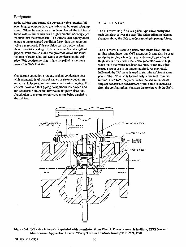
3.1.2 T/T Valve
The T/T valve (Fig. 3.4) is a globe-type valve configured such that flow is over the seat. The valve utilizes a balance chamber above the disk to reduce required opening forces.
The T/T valve is used to quickly stop steam flow into the turbine when there is an OST actuation. It may also be used to trip the turbine when there is evidence of a pipe break (high steam flow), when the steam generator level is high, when main feedwater has been restored, or for any other reason system use is no longer required. As previously indicated, the T/T valve is used to start the turbine at some plants. The T/T valve is located only a few feet from the turbine. Therefore, the potential for the accumulation of slugs of condensate downstream of the valve is decreased from the configurations that start the turbine with the SAV.
BALANCE CHAMBER PRESSURE TAP
PILOT VALVE AND STEH
NEEDLE VALVE
FIXED ORIFICE
Figure 3.4 T/T valve internals. Reprinted with permission from Electric Power Research Institute, EPRI Nuclear Maintenance Application Center, 'Terry Turbine Controls Guide," NP-6909,1990
NUREG/CR-5857 10

Equipment balanced to reduce the amount of force required to move the valve. The major differences between the valves lie in the configuration of the valve plug, seat, guides, and stem connection.
On the 21/2-in. valve the guides are installed in the valve body before final machining. The guides for the 3-in. valve are actually enclosed in an extension of the valve bonnet. Both the V-port and the venturi seat are welded into the valve body.
The stem connection for the 21/2-in. valve is a T-slot in the plug, with a matching head on the valve stem. The venturi seat valve stem is connected directly to the plug. This type of connection requires that the stem and plug be concentric to prevent binding.
3.1.4 Turbine
The turbine (Fig 3.7) is a horizontally split casing, solid wheel design, with the steam inlet and exhaust in the lower half of the casing. This permits maintenance and inspection on the turbine without disturbing piping or turbine-to-pump alignment. The rotor assembly (turbine wheel) is solid, unlike conventional bladed turbines. Small "buckets" are machined into the circumference of the rotor. This allows the turbine to function with moist steam or even water
•BALANCE PORTS
Figure 3.6 3-in. governor valve. Reprinted with permission from Electric Power Research Institute, EPRI Nuclear Maintenance Application Center, "Terry Turbine Controls Guide," NP-6909,1990
3.1.3 Governor Valve
Two basic governor valve types are available for use in RCIC and AFW turbines: a 2 1/2-in. V-port throttle valve (see Fig 3.5) and a 3-in. venturi seat throttle valve (see Fig. 3.6). Both valves are single seated and pressure
Figure 3.5 2-1/2-in. governor valve. Reprinted with permission from Electric Power Research Institute, EPRI Nuclear Maintenance Application Center, "Terry Turbine Controls Guide," NP-6909,1990
11 NUREG/CR-5857

Equipment
\
MECHANICAL GOVERNOR
TRtMTHR0TTLE VALVE
TURBINE WHEEL
BEARINGS
Figure 3.7 Basic turbine conflguration. Reprinted with permission from Dresser-Rand Corporation
slugs without destroying the rotor assembly. The shaft seals (glands) are carbon type and are nonlubricated. Leakoff is drained away in separate piping.
The lubricating oil system is operated by a gear-driven pump that operates directly off the turbine (Fig. 3.8). The oil pump supplies oil to the turbine bearings, and on turbines equipped with EGs, it supplies pressure for governor operation also.
3.1.5 Governor
The turbine governor system receives the flow controller signal output and converts it into mechanical motion to
position the turbine governor valve to maintain the turbine at the referenced speed (Fig. 3.1). The turbine governor system is calibrated so maximum and minimum flow requirements are met.
3.1.6 Overspeed Trip Mechanism
The OST mechanism (Fig. 3.9) is composed of three basic components: (1) a speed-sensing device, (2) the trip linkage, and (3) the TH" valve (see Sect. 3.1.2). The speed-sensing device is attached to or integral with the turbine shaft and is eccentrically weighted. The centrifugal force generated by turbine shaft speeds in excess of predetermined limits will cause the weight to move radially outward, striking a tappet. Tappet movement causes the
NUREG/CR-5857 12

Equipment
(PUMP OIL PRESSURE
[SUPPLY OIL
| TRAPPED OIL & POWER CYLINDER OIL PRESSURE
I SUMP OIL PRESSURE
NEEDLE VALVE-
•-, TO ELECTRIC CONTROL BOX
-COMPENSATION LAND
-PILOT VALVE BUSHING (ROTATING)
-CONTROL LAND
PUMP "GEARS
INCREASE FUEL
. _ J
NOTE: SERVO DIRECTIONS SHOWN ARE FOR DIRECT-ACTING, FOR REVERSE-ACTING SERVO DIRECTION REVERSED.
INCOMING OIL SUPPLY
Figure 3.8 Electronic governor remote (EGR) schematic. Reprinted with permission from Woodward Governor Company
spring-loaded trip linkage to actuate and thus close the T/T valve.
Once the valve trips, it must be manually reset for turbine operation to resume. First the connecting rod (Fig. 3.9) must be reset. This requires that an operator grab the connecting rod and pull it toward the T/T valve against the trip spring force. At this time the operator must also verify that the trip tappet has dropped down to its normal position, where it will rest against the flat face of the head lever. The tension on the connecting rod is then released. The T/T valve must then be cranked closed, using the handwheel or the motor operator, to relatch the trip hook and latch lever. Then the valve must be opened, manually or electrically, to permit flow through the valve.
As an option, some turbines are equipped with an electronic overspeed sensing and trip device. The signal from the frequency to voltage converter is also the input to a switch located in the tachometer circuitry. When turbine shaft speed exceeds a preset value (which is lower than the
mechanical OST set point), relay contacts close. This sends a trip signal to the trip solenoid, which is located on the T/T valve, resulting in a turbine trip. The advantage to the electronic OST is the ability to remotely reset the trip. This cannot be done with the mechanical OST device.
Many facilities removed the electronic OST devices because an electronic OST was immediately followed by a mechanical OST. The time difference between the electronic OST and a decrease in turbine speed was not small enough to prevent the mechanical OST. Therefore, the advantage of a remote OST reset was not realized. The addition of OST circuitry added the potential for inadvertent tripping without increasing safety, reliability, or convenience. Reliability of the turbine was thus potentially compromised without any apparent benefit On the other hand, some utilities increased the trip point on the electronic OST from 110 to 125% of normal operating speed and have enjoyed successful and reliable operation of the device. At these plants, raising the electronic OST set point minimized trips caused by startup transients.
13 NUREG/CR-5857

Equipment
TURBINE SHAFT
MECHANICAL OVERSPEED TRIP MECHANISM
Figure 3.9 Mechanical OST mechanism
3.2 HPCI Turbine—Operation Overview
On initiation of the HPCI system, the motor-driven auxiliary oil pump for the turbine forced feed lubrication system starts simultaneously with the opening of the motor-operated steam line shut-off valve (supplied by others), located upstream of the hydraulically operated turbine stop valve. As oil pressure is established in the turbine hydraulic system, the multistage governor valves will go to the "full open" position closely followed by the opening of die turbine stop valve.
or to some speed relative to the output signal from the flow controller, which results in satisfactory "pump flow" demand.
At almost the same time that the turbine starts to roll, the turbine governing system (sensing speed) actuates the governor valves, via remote hydraulic servomotor and oil relay, to a position relative to me ramp generator signal converter output signal demand. Thus, this action provides acceleration control without OST through the ramp rate of the ramp generator.
At essentially the same time as the turbine stop valve leaves its seat from the "fully closed" position, the turbine governor system "ramp generator" function is initiated by the mechanical movement of the valve stem actuating a valve position indicator switch.
The "ramp" generator will ramp from an "idle" turbine speed set point to the rated "high" turbine speed set point
As flow is developed and reaches the set point of the flow controller, the flow controller output signal to the turbine governor will adjust to where constant rated pump flow is oblained.
As pump discharge and steam inlet pressure change wim a variable reactor pressure range, an appropriate controller output signal will be sent to the turbine to maintain constant steady state pump flow.
NUREG/CR-5857 14

Equipment
The system consists of the following major components, similar to the AFW/RCIC turbine systems: • SAV, • stop valve, • governor valve, • turbine, • governor, and • OST mechanism.
3.2.1 Steam Admission Valve
The SAV performs the same function in this system as it does in the AFW/RCIC systems: opening to admit steam to the governor valve for a turbine start. See Sect. 3.1.1 for more information on this valve.
3.2.2 Stop Valve
The Terry Corporation Model CS/CCS turbine stop valve (Fig. 3.10) is an inverted, oil-operated, semibalanced globe-type valve. Hydraulic pressure in the hydraulic cylinder (part 15) is used to open the valve, and spring force and steam pressure close the valve when the hydraulic pressure is dumped through a pilot valve mounted on the hydraulic cylinder.
The stop valve is equipped with limit switches for open/ close indication and ramp initiation and with an internal steam strainer on all but some of the oldest models.
During a typical opening cycle (see Fig. 3.10), an oil signal pressure of ~20 psig at connection (26) will compress the spring (22) and shift the relay valve piston (18) to close the drain opening in body (19), and then open a passage for the main oil supply through an inlet connection (21), around relief in the piston (18), and into the hydraulic cylinder (15). [Oil entrapped in the spring case area (22) is discharged through the relay piston (18) to the drain line.] An orifice in the relay body will admit ~9 gal/min of oil into the hydraulic cylinder (15), which limits the valve opening time. A drain-off bypass flow control (28) is provided but has been determined unnecessary for timing purposes and is normally closed or removed with the piping plugged.
The hydraulic cylinder piston rod is connected with a split coupling (36) to the stop valve stem (45). During the first 1/4 in. of stem stroke, the pilot in the disk opens, and the balancing chamber is evacuated to the downstream side of the valve chest. When the pilot valve begins to lift the main disk, the pressure in the balancing chamber has reduced to a minimum value, partially balancing the main disk. For
the remaining 2.5 in. of stroke, the flow area between the disk (47) and seat (46) increases. Switch (11) left is tripped when the valve is in full open position.
When closing, the oil signal pressure at (26) drops to -12 psig; the spring (22) exerts sufficient force to shift the relay valve piston (18). The open passage of the main oil supply is first cut off, and then additional piston movement opens the oil discharge port between the hydraulic cylinder (15) and the oil discharge connection. The high-pressure oil discharge drives the relay piston to its relaxed position. A compression spring in the hydraulic cylinder (15) actuates closure of the valve proper and forces the oil from the main cylinder through the dump port. The pilot valve (45) seats in the disk (47), which seats on body seat (46) to provide a tight seal. Internal pressure acting on the disk (47) assists the hydraulic operator unit in tight seating. Switch (11) right is tripped when the valve is in full-closed position.
3.2.3 Governor Valve
The governor valve for the HPCI turbine is different in configuration, but not function, from the governor valve for the AFW/RCIC turbine. The governor valve for the HPCI turbine consists of five ports (hence, the term multiport), which open in sequence (see Fig. 3.11). This allows more control over the HPCI turbine, which is larger than the GS-2 series used for the AFW/RCIC. In function, however, die principle of operation is the same, with the governor valves opening on turbine start to control the amount of steam admitted to the turbine.
3.2.4 Turbine
The majority of the HPCI turbines in service were manufactured by the Terry Corporation (currently a division of Dresser Rand Corporation), and are models CS or CCS turbines. These turbines are similar in construction to the GS-2N turbines used extensively in AFW/RCIC systems. However, these turbines are quite a bit larger (~5500 hp vs 2000 hp for the GS-2 model) and more powerful. Like the GS-2 turbines, the steam supply can range in pressure from 150 to 1100 psi. Turbine configuration, however, remains similar and is covered in Sect. 3.1.4.
3.2.5 Governor
The Woodward EG governor used on the HPCI turbine is almost identical in composition and function to the type used on AFW/RCIC systems. The description of governor configuration and operation is detailed in Sect. 3.1.5.2.
15 NUREG/CR-5857

ClOCKWISE = DECREASE BALANCE CHAMBER PRESSURE COUNTER-CLOCKWISE = INCREASE BALANCE CHAMBER PRESSURE
BALANCE CHAMBER PRESSURE
STEAM INLET (ABOVE SEAT) PRESSURE
PARTS LIST NO. PART NO. PART NO. PART NO. PART
1 FLAT SETSCREW 16 STUD 31 BENT PIPE 46 SEAT 2 SOCKET PIPE PLUG 17 HEX NUT 32 HEX NUT 47 DISC 3 HOLLOW LOCK SCREW 18 RELAY VALVE PISTON 33 HEX NUT 48 DISC FLANGE 4 STRAINER BASKET 19 RELAY VALVE BODY 34 CAPSCREW 49 SOCKET HD. CAPSCREW 5 BODY 20 PIPE 35 HEX NUT 50 FLEX1TALUC GASKET 6 NIPPLE 21 FLANGE 36 SPLIT COUPLING 51 STUD 7 NIPPLE 22 COMPR. SPRING 37 YOKE 52 HEX NUT 8 STUD 23 PISTON RING 38 LEAK-OFF BUSHING 53 COVER WITH CYLINDER 9 HEX NUT 24 RELAY VALVE COVER 39 STUD 54 ADJUSTING ROD 10 BOTTOM STUFFING BOX 25 CAPSCREW 40 HEX NUT 55 DISC 11 SWITCH 26 FLANGE 41 DISTANCE WASHER 56 LOCK NUT 12 SWITCH BRACKET 27 PIPE 42 NIPPLE 57 COMPR. SPRING 13 FLANGE 28 NEEDLE VALVE 43 BENT NIPPLE 58 SPRING CASE 14 PIPE 29 PIPE 44 FLEXITALLIC GASKET 59 CAP 15 HYDR. CYLINDER 30 UNION 45 PILOT VALVE WITH STEM
CD S3
view - "A " BALANCE CHAMBER PRESSURE
ADJUSTMENT COMPONENTS
STEAM STRAINER-
BALANCE CHAMBER -
NOTE: ONLY PARTS PERTINENT TO DISCUSSION ARE BALOONED.
3/4"-PIPE TAP
(NORMALLY PLUGGED)
<gr-
SEE VIEW " A "
DRAIN
-CLOSED-LOWER LIMIT SWITCH (11R) -OPEN-UPPER LIMIT SWITCH (11L)
HYDRAULIC CYLINDER (SEE FIG. 8 -6 )
• ABOVE SEAT DRAIN
MOUNTED VERTICALLY
Figure 3.10 HPCI stop valve. Reprinted with permission from Electric Power Research Institute, EPRI Nuclear Maintenance Application Center,« Turbine Controls Guide," NP-6909,1990

Equipment
INLET CONTROL VALVE TYPICAL (5 )
CONTROL VALVE SEAT TYPICAL ( 5 )
STEAM CHEST COVER
LIFTING BEAM
STEAM CHEST
VALVE NUMBERS — I — H — m — TX — Y *
OPENING SEQUENCE — 4 — 2 — 1 — 3 — 5
Figure 3.11 Multiport HPCI governor valve. Reprinted with permission from Electric Power Research Institute, EPRI Nuclear Maintenance Application Center, "Terry Turbine Controls Guide," NP-6909,1990
3.2.6 Overspeed Trip Mechanism
The OST system for HPCI turbines (see Fig. 3.12) resembles the trip mechanism for the AFW7RCIC turbines in that there is a shaft-mounted trip pin, a trip mechanism, and a valve that isolates steam to the turbine. However, for die HPCI turbine the trip mechanism is replaced by a hydraulic trip valve assembly, and the T/T valve is replaced by the turbine stop valve.
The shaft-mounted trip pin resembles the type used for the AFW/RCIC turbine. It is shaft-mounted and eccentrically weighted, moving outward to strike die trip tappet when the centrifugal force generated by the rotating turbine shaft exceeds a preset limit. At mis speed the trip pin moves radially outward, having overcome the force of die spring
mat normally holds me trip pin in position, and strikes me trip tappet of me hydraulic trip valve.
The hydraulic trip valve assembly allows (he pressurized oil, which holds me stop valve open, to drain to me sump. This will happen as a result of the trip tappet being struck by the shaft-mounted trip pin. When the oil pressure is reduced, a spring in me stop valve forces me piston closed. Unlike die mechanical linkage of me AFW/RCIC turbines, me HPCI OST mechanism wiD automatically reset after a predetermined amount of time has elapsed.
Limit switches and remote lights indicate whether the stop valve is open, shut, or in an intermediate position.
17 NUREG/CR-5857

Equipment
ITEM DESCRIPTION ITEM DESCRIPTION 1 .CAP SCREW 13 TAPPET ASS'Y. 2 SET SCREW 14 PEDASTAL CAP 3 RESET KNOB 15 SO. KEY 4 SPRING ADJ. SLEEVE 16 SET SCREW 5 HEX JAM NUT 17 EMERG. WEIGHT ADJ. SCREW 6 CAP SCREW 18 EMERG. TRIP WEIGHT 7 EMERG. VALVE BODY CAP 19 TURBINE SHAFT 8 SPRING 20 EMERG. TRIP DISC 9 PIPE PLUG 21 EMERG. WEIGHT SPRINC 10 COTTER PIN 22 EMERC. SPRING ADJ. SCREW 11 PISTON 23 GASKET 12 VALVE BODY
Figure 3.12 HPCI trip valve assembly. Reprinted with permission from Electric Power Research Institute, EPRI Nuclear Maintenance Application Center, "Terry Turbine Controls Guide," NP-6909,1990
NUREG/CR-5857 18

4 Analysis of Operational Data
4.1 Introduction
Historical failure data were gathered from LERs and the NPRDS and placed in a data base. The data collected included the following fields: • reporting site, • description narrative, • cause narrative, • corrective action narrative • date of failure start, and • method of failure detection.
The data were then examined to determine events that had been recorded in both NPRDS and on an LER. Duplicate events were then removed from the data base. At this point fields were added to allow the addition of codes to permit categorization: 1. Major component group—the six major components:
SAV T/T governor valve turbine governor OST
2. Subcomponent—the piece part or subcomponent actually involved in the failure.
3. Cause—a code assigned to the failure based on a review of the description narrative, independent of the cause reported by the utility.
The resulting data base had 375 individual failures, ranging in time from 1984 to 1991. Each event was then reviewed, analyzed, and categorized.
4.2 Data Analysis
The failure records were reviewed and characterized by component group, method of detection, plant age at failure, calendar year, and affected plant. Summaries of the results of these characterizations follow.
4.2.1 Failure Data Analysis by Component Group
The initial evaluation of failures resulted in seven categories: five of the six major categories plus categories for reports of turbine failures that were caused by associated devices (see Fig. 4.1). Those failures attributed directly to
Associated Devices
5%
OST
Trip/Throttle Valve
3%
Governor 39%
Turbine 23% Governor Valve
10%
Figure 4.1 Percentage of total failures by component
19 NUREG/CR-5857

Analysis
the SAV have been included with the failures of associated devices. The data did not consistently indicate when a failure could be attributed to the SAV because these failures can be reported with either the main steam system or the AFW system. Accounting for all failures of the SAV would require identifying the component identification number for the SAV at each plant. Then all valve failures in both the main steam system and the AFW system would have to be evaluated to find failures of these particular valves. An effort of this magnitude was not deemed justifiable for this report. The failures caused by associated devices were random in nature and did not show any repeatable pattern. Therefore, they were omitted from the rest of the report.
Evaluation of the data after categorizing by component group reveals the governor as the single component that fails most often, followed by the turbine, mechanical OST mechanism, and the governor valve. Component-specific details are discussed in Sect. 4.3.
4.2.2 Method of Detection
The failure records were reviewed to determine how failures were discovered. The following categories were established:
• Demand failures—Failures that occur when the system is called on to function in a nontest situation.
Programmatic testing failures—Failures that occur during surveillance, postmaintenance testing, or periodic operability testing. Also included are instances where the turbine may not have failed to operate, but had been declared inoperable due to unacceptable oil samples.
Inspection—Category that includes both in-service inspection and any special inspection that indicated unacceptable performance.
Maintenance—Any unacceptable conditions discovered during preventive or corrective maintenance.
Observation—Those unacceptable conditions that are observed as part of an individual's normal job. This includes operators, system engineers, or any other person who periodically examines the turbine for visible degradation or breakage.
The data indicate that the highest percentages of failures are detected during scheduled (programmatic) testing (55%) (see Fig. 4.2). This trend is consistent for each year examined. The second most prevalent method of detection was a demand failure (19%), followed by the combination of routine and incidental observation (13%).
4.2.2.1 Programmatic Testing Failures
The majority of the failures examined were discovered by programmatic means. Programmatic discoveries
Observation 13%
Programmatic 55%
Inspection 8%
Maintenance 5%
Demand Failure 19%
NUREG/CR-5857
Figure 4.2 Failure by method of detection
20
Analysis
outnumbered demand discoveries by almost a factor of 4 to 1. Programmatic discoveries include routine surveillance testing, in-service inspection, and routine observation by persons such as system engineers who walk down systems on a regular basis.
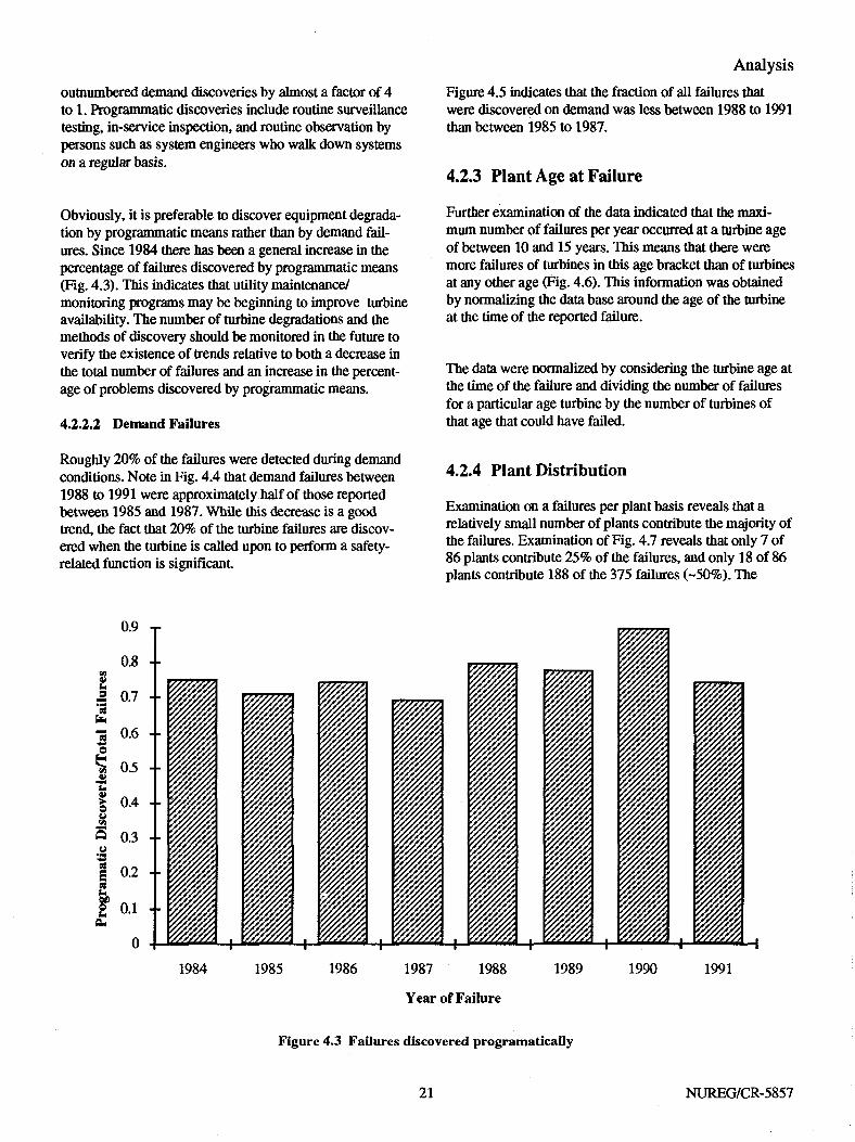
Obviously, it is preferable to discover equipment degradation by programmatic means rather than by demand failures. Since 1984 there has been a general increase in die percentage of failures discovered by programmatic means (Fig. 4.3). This indicates that utility maintenance/ monitoring programs may be beginning to improve turbine availability. The number of turbine degradations and the methods of discovery should be monitored in the future to verify the existence of trends relative to born a decrease in the total number of failures and an increase in die percentage of problems discovered by programmatic means.
4.2.2.2 Demand Failures
Figure 4.5 indicates mat the fraction of all failures that were discovered on demand was less between 1988 to 1991 than between 1985 to 1987.
4.2.3 Plant Age at Failure
Further examination of the data indicated that the maximum number of failures per year occurred at a turbine age of between 10 and 15 years. This means mat mere were more failures of turbines in mis age bracket than of turbines at any omer age (Fig. 4.6). This information was obtained by normalizing the data base around me age of me turbine at the time of the reported failure.
The data were normalized by considering the turbine age at the time of the failure and dividing the number of failures for a particular age turbine by the number of turbines of that age that could have failed.
Roughly 20% of the failures were detected during demand conditions. Note in Fig. 4.4 that demand failures between 1988 to 1991 were approximately half of those reported between 1985 and 1987. While this decrease is a good trend, me fact that 20% of die turbine failures are discovered when the turbine is called upon to perform a safety-related function is significant.
4.2.4 Plant Distribution
Examination on a failures per plant basis reveals Uiat a relatively small number of plants contribute the majority of me failures. Examination of Fig. 4.7 reveals mat only 7 of 86 plants contribute 25% of me failures, and only 18 of 86 plants contribute 188 of the 375 failures (-50%). The
1984 1985 1986 1987 1988
Year of Failure
1989 1990 1991
Figure 4.3 Failures discovered programatically
21 NUREG/CR-5857
Analysis reader is cautioned against drawing conclusions based on this limited amount of data. Many variables could potentially contribute to these figures. The quality of reporting by individual utilities varies from plant to plant. Reporting may even change at the same plant with changes in personnel and reporting practices. There have also been instances where failures accumulated against a particular plant while the vendor went through an iterative process of subcomponent redesign and replacement.
4.2.5 Failure Data Analysis by Year
Analysis of the failure data by year reveals no definitive trends that can be determined from a graphic representation of the failure data. A discussion of component failures by year and failures by method of detection and year follow.
4.2.5.1 Failures by Component and Year
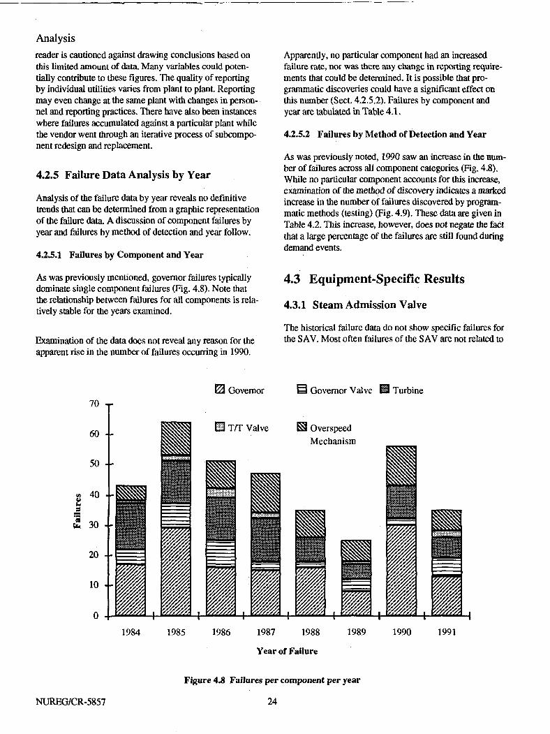
As was previously mentioned, governor failures typically dominate single component failures (Fig. 4.8). Note that the relationship between failures for all components is relatively stable for the years examined.
Examination of the data does not reveal any reason for the apparent rise in the number of failures occurring in 1990.
Apparently, no particular component had an increased failure rate, nor was there any change in reporting requirements that could be determined. It is possible that programmatic discoveries could have a significant effect on this number (Sect. 4.2.5.2). Failures by component and year are tabulated in Table 4.1.
4.2.5.2 Failures by Method of Detection and Year
As was previously noted, 1990 saw an increase in the number of failures across all component categories (Fig. 4.8). While no particular component accounts for this increase, examination of the method of discovery indicates a marked increase in the number of failures discovered by programmatic methods (testing) (Fig. 4.9). These data are given in Table 4.2. This increase, however, does not negate the fact that a large percentage of the failures are still found during demand events.
4.3 Equipment-Specific Results
4.3.1 Steam Admission Valve
The historical failure data do not show specific failures for the S AV. Most often failures of the S AV are not related to
m Governor S Governor Valve H Turbine
T/T Valve S3 Overspeed Mechanism
1984 1985 1986 1987 1988 1989 1990 1991
Year of Failure
NUREG/CR-5857
Figure 4.8 Failures per component per year
24

Analysis Table 4.1 Summary of failures by component and year
Component
Year Governor , Turbine valve
OST T/T valve Controls Other/
unknown Total
1984 17 5 15 5 1 0 1 44 1985 29 8 14 11 2 5 0 69 1986 16 9 14 9 3 0 3 54 1987 15 3 14 13 2 0 2 49 1988 16 2 8 9 0 1 3 39 1989 8 4 5 7 1 1 1 27 1990 30 2 11 13 0 1 1 58 1991 13 6 7 7 2 0 0 35 Total 144 39 88 74 11 8 11 375
Observation D Inspection 70 -r
Maintenance E Demand failure D3 Testing
1984 1985 1986 1987 1988
Year of Failure
1989 1990 1991
Figure 4.9 Number of failures per year by method of discovery
the turbine in failure reporting. To discover these failures would require identifying the S AV for each facility, tabulating all failures for that valve, and subsequently identifying those that could have or did impact turbine operation. However, failures associated with the SAV are often manifested as unexplained OSTs. This type of failure is covered in Sect. 3.1.1.3.
4.3.2 Turbine
Of the 88 problems associated with the turbine, ~40% of the failures examined were traceable to the lubricating oil system or to subcomponents that are directly dependent on the lubricating oil system (bearings) to maintain function. Bearing failures were the most prevalent (18) of failures
25 NUREG/CR-5857

Analysis
Table 4.2 Summary of failures by method of detection
Year
Method of discovery 1984 1985 1986 1987 1988 1989 1990 1991 Total
Observation 7 g 7 g 6 1 11 1 49 Inspection 5 6 5 5 4 2 3 1 31 Maintenance 4 4 2 2 1 1 2 1 17 Demand failure 7 16 12 13 7 5 4 g 72 Testing 21 35 28 21 21 18 38 24 206 Total by year 44 69 54 49 39 27 58 35 375
with the most significant consequences and are most often discovered by high-bearing temperatures as monitored by thermocouples installed in the bearing housings.
ber than occurrences like governor valve failures (Fig. 4.1), their significance relative to turbine operability makes them less important than other failures.
The data examined did not reveal any turbine trips due to failed bearings. The data indicate a decrease in the number of bearing failures per year since 19g6. This trend is consistent with the pattern of failures for all subcomponents.
The other 60% of problems associated with the turbine had the potential to affect turbine operation on a long-term basis but did not jeopardize the performance of the safety-related function at the time of failure discovery. Such instances include minor oil leaks, gasket leaks, and lube oil sight glass leaks. While such instances total a greater num-
The distribution of turbine-related failures is provided in Fig. 4.10 and Table 4.3.
4.3.3 Governor Valve
While more failures were reported for the turbine than the governor valve, the failures associated with the governor valve must be examined in light of the potential to affect turbine operation, not just the volume of failures. The distribution of causes for governor valve failures is provided in Fig. 4.11 and Table 4.4.
Other 36%
Leaks 13%
Bearings 20%
Oil Contamination 8%
GE Turbine Specific
Auxiliary Oil Pump
Lube Oil Components
Figure 4.10 Breakdown of turbine failures
NUREG/CR-5857 26

Analysis Table 43 Breakdown of reported turbine failures
Year
Subcomponent 1984 1985 1986 1987 1988 1989 1990 1991 Total
Bearings 0 3 7 5 1 1 0 1 18 Oil contamination 3 0 0 0 2 0 1 1 7 Leaks 1 2 0 1 1 0 2 4 11 GE turbine specific 2 1 0 3 0 1 0 0 7 Auxiliary oil pump 1 2 0 1 0 0 1 0 5 Lube oil components 2 2 2 0 1 0 1 0 8 Other 6 4 5 4 3 3 6 1 32 Total 15 14 14 14 8 5 11 7 88
Other 13% Out of Adjustment
18%
Poor Lubrication 5%
Bent Stem 5%
Rust/Corrosion 5%
Wear 21%
Binding 28%
Figure 4.11 Breakdown of governor valve failures
Governor valve malfunctions have manifested themselves in five basic areas, which are often interrelated: • stem corrosion, • packing leaks, • bent valve stems, • linkage adjustment, and • wear.
When failures attributed to binding are included with these categories, -82% (32 of 39) of the failures are accounted for. Binding may take the form of stem travel impairment, which may result in erratic behavior or a complete lockup of the valve stem.
Stem corrosion in the governor valve is often evidenced by a buildup of deposits along the portion of the valve stem
27 NUREG/CR-5857

Analysis
Table 4.4 Breakdown of reported governor valve failures
Year
Cause of failure 1984 1985 1986 1987 1988 1989 1990 1991 Total
Out of adjustment 1 1 2 1 1 1 0 0 7 Wear 0 2 2 0 0 0 2 2 8 Binding 3 2 2 0 1 0 0 3 11 Rust/corrosion 0 0 0 1 0 1 0 0 2 Bent stem 0 1 1 0 0 0 0 0 2 Poor lubrication 0 0 0 0 0 1 0 1 2 Leaks 1 0 1 0 0 0 0 0 2 Other 0 2 1 1 0 1 0 0 5 Total 5 8 9 3 2 4 2 6 39
exposed to steam. These deposits are caused by the presence of moisture from operation of the turbine. When stored in a hot wet condition for extended periods of time, corrosion is a distinct possibility. It is the interference of the corrosion deposits with the carbon rings that make up the valve packing that causes binding in the governor valve. In the data examined, binding accounted for 28% of the governor valve failures.
Corrosion deposits on the valve stem do not automatically cause demand failures. However, cycling of the governor valve during operation can lead to accelerated wear of the carbon rings in the governor valve packing. The wear of the carbon rings can reduce the ability to seal against the valve stem, resulting in packing leaks. Once a leak has developed, the escaping steam can also act to accelerate packing wear.
degraded governor valve response times. However, bent stems accounted for a small percentage of the governor valve failures.
Almost one-fourth (18%) of the failures attributed to the governor valve are related to the governor valve linkage. These problems normally relate to either adjustment of the linkage or binding due to the accumulation of dirt, caked grease, etc. Periodic adjustment is required to compensate for normal wear in the governor valve/linkage. The problem with dirt/contaminants appears to be caused by excess lubrication. While insufficient lubrication causes binding of the mechanism, excess lubrication tends to collect dirt, debris, and also cake over time. All of this serves to degrade the performance of the governor valve linkage.
4.3.4 Governor Malfunctions
Review of the operating experience also indicated several failures that can be traced to the governor valve, where degradation of the governor valve could not be identified at the time of inspection. Utility personnel have postulated that thermal expansion of the valve plug has contributed to binding between the plug and the sleeve for certain valves. A design change in 1980 increased the sleeve bore, effectively reducing the possibility of binding due to thermal expansion.
Regardless of the reason, once governor valve plug movement is restricted, it is possible to cause deformation of the stem by buckling. Such restrictions are typically caused by corrosion of the plug and stem. By the time the plug breaks free (from governor servomotor force), permanent deformation of the stem can occur (buckling). The excess packing drag created by a bend could then cause erratic behavior in turbine control, with the potential for OSTs from
Governor malfunctions accounted for a large percentage of the reported failures in the data examined (see Fig. 4.12). However, the number of reports of governor problems is not an accurate measure of governor reliability. One should not expect the governor to perform beyond its design limitations or without adequate maintenance. Listed below are the predominant reasons for apparent governor malfunction: • dirty oil, • water-contaminated oil, • particulate contaminants, • maladjustment/set point drift, and • miscellaneous damage.
The narrative for many failures did not specify the failed subcomponent; the only identifier used was "governor." These causes of failure are individually discussed and tabulated below (see Fig. 4.13 and Table 4.5). Note that those
NUREG/CR-5857 28

Analysis
EGM 17%
EGR 20%
Governor 49%
Speed Control Sensor
Figure 4.12 Predominant governor subcomponent failures
Unknown 18%
Figure 4.13 Predominant governor failure causes
29 NUREG/CR-5857
Analysis Table 4.5 Predominant governor failure causes
Cause Number of failures
Unknown 26 Age/wear 19 Rust/corrosion 3 Human error 17 Out of calibration/adjustment 23 Dirt/contaminants 16 Binding 6 Mechanical failure 13 Contaminated oil 7 Other 14 Total 144
turbines that use EGs draw the governor control oil from the turbine sump. This shared oil system increases the possibility of control oil contamination for these governors due to contamination of the turbine lubricating oil.
4J.4.1 Contaminated OH
The quality of the oil used in the governor is critical to its proper function. Supplement 2 to NRC Information Notice 86-14 (Ref. 4) clearly demonstrates performance degradation due to dirty oil. For purposes of this report, dirty oil will be called contaminated oil. Oil contamination can come from several sources: worn bearings, contaminants introduced when the oil was put in the turbine, poor housekeeping during maintenance, leftover machine filings from manufacturing, turbine wear [electronic governor remote/ electronic governor speed control (EGR/EGM) systems], buildup from infrequent changes, and clogged filters.
4.3.4.2 Water Contamination
Water contamination of the governor control oil accounts for ~2% of the reported governor failures and 5% of the reported failures for the turbine.
Water contamination has two primary sources: leaking oil coolers and leaking steam seals. Once steam has leaked past the shaft seals, it can condense and contaminate the control oil. For EG systems, the shaft seals most affected are the turbine shaft seals. For PG-type governors, leakage past the governor drive shaft is the most probable path of steam leakage.
Water in the control oil also tends to change the viscosity of the control oil, thus changing the operating characteris
tics of the governor. In addition to changes in the operating characteristics of the governor, water contamination can cause rust on the governor internals by degrading the oil.
43.4.3 Particulate Contaminants
Particulate contamination causes loss of governor function by restricting the flow of control oil in the governor. These contaminants enter the governor in several ways. Dirt most easily enters the governor during oil checks or replacement. Once the filler plug is removed, any debris in the vicinity of the filler hole can fall into the governor. Other particulates that can affect governor performance include debris from wear of internal machined parts. Metal filings can accumulate, causing clogging of both orifices and oil passages. Electronic governors must also contend with debris that is introduced to the control oil from the turbine sump. Finally, corrosion products associated with water contamination can result in loose particulate.
43.4.4 Maladjustment/Set Point Drift
Problems associated with maladjustment are typically failure to follow procedures. Set point drift, on the other hand, will occur due to natural wear of components, but it is difficult to quantify because it is not reported as a failure unless it leads to turbine inoperability. Drift that is corrected as part of a normal preventive maintenance program will not show up in the data bases. The problem of set point drift, which can easily lead to turbine inoperability, is simple to avoid with periodic calibration of the turbine.
43.4.5 Miscellaneous Damage
Miscellaneous damage to the governor is breakage that does not occur as a result of operation. When climbing in the vicinity of the governor and using instrument air lines, sensors, and control oil lines as handholds or steps, various plant personnel, including maintenance workers and operations personnel, can break governor subcomponents. However, such degradation is not a product of governor aging or direct service wear.
4.3.5 OST Mechanism
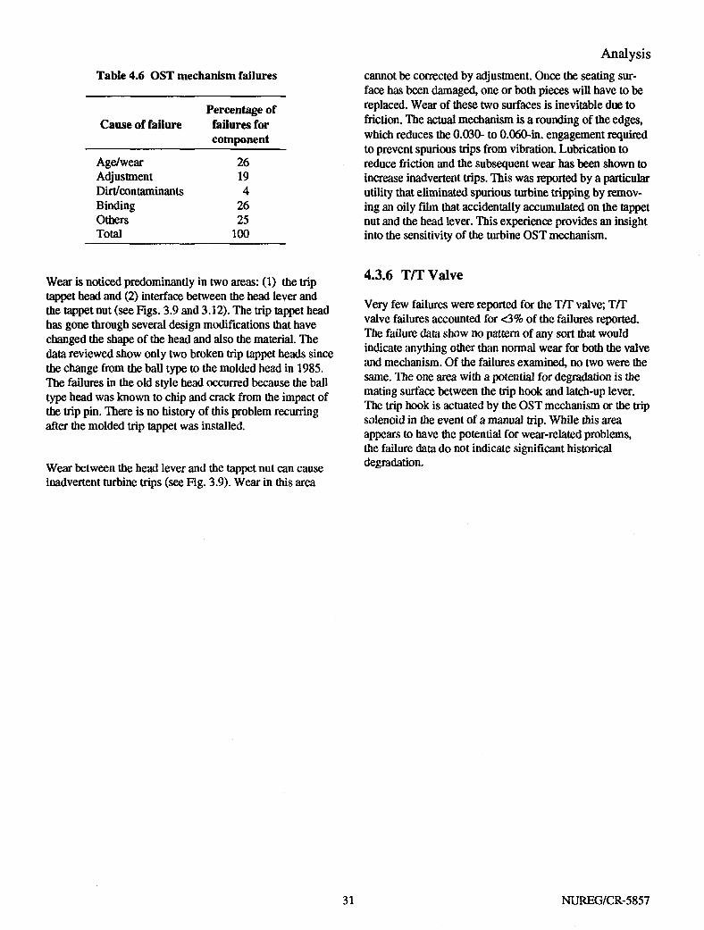
Mechanical OST mechanism failures account for roughly 20% of the reported failures (Table 4.6). Of the failures attributed to this mechanism, three areas show the greatest potential for degradation: component wear (26% of trip mechanism problems), binding in the mechanism (26%), and mechanism adjustment (19%). Dirt accounts for another 4% of the mechanism problems, with various other nonrecurring failures making up the other 25%.
NUREG/CR-5857 30
Analysis
Table 4.6 OST mechanism failures
Percentage of Cause of failure failures for
component
Age/wear 26 Adjustment 19 Dirt/contaminants 4 Binding 26 Others 25 Total 100
Wear is noticed predominantly in two areas: (1) the trip tappet head and (2) interface between the head lever and the tappet nut (see Figs. 3.9 and 3.12). The trip tappet head has gone through several design modifications that have changed the shape of the head and also the material. The data reviewed show only two broken trip tappet heads since the change from the ball type to the molded head in 1985. The failures in the old style head occurred because the ball type head was known to chip and crack from the impact of the trip pin. There is no history of this problem recurring after the molded trip tappet was installed.
cannot be corrected by adjustment. Once the seating surface has been damaged, one or both pieces will have to be replaced. Wear of these two surfaces is inevitable due to friction. The actual mechanism is a rounding of the edges, which reduces the 0.030- to 0.060-in. engagement required to prevent spurious trips from vibration. Lubrication to reduce friction and the subsequent wear has been shown to increase inadvertent trips. This was reported by a particular utility that eliminated spurious turbine tripping by removing an oily film that accidentally accumulated on the tappet nut and the head lever. This experience provides an insight into the sensitivity of the turbine OST mechanism.
4.3.6 T/T Valve
Very few failures were reported for the T/T valve; T/T valve failures accounted for <3% of the failures reported. The failure data show no pattern of any sort that would indicate anything other than normal wear for both the valve and mechanism. Of the failures examined, no two were the same. The one area with a potential for degradation is the mating surface between the trip hook and latch-up lever. The trip hook is actuated by the OST mechanism or the trip solenoid in the event of a manual trip. While this area appears to have the potential for wear-related problems, the failure data do not indicate significant historical degradation. Wear between the head lever and the tappet nut can cause
inadvertent turbine trips (see Fig. 3.9). Wear in this area
31 NUREG/CR-5857


5 Testing
5.1 Background The purpose of periodic testing is to provide a quantifiable method of ensuring that the turbine will perform the intended function when an automatic start signal is received. Test results should confirm that the turbine will bom start in a controlled manner and maintain the reference speed without evidence of erratic behavior. Testing should simulate the environment and system conditions for a demand start as closely as possible, including temperature and pressure transients, time constraints, and system status (cold start vs hot start).
Current test requirements were identified, and historical failures were examined to determine which components were failing. This was followed by analysis of we failures to determine whether the degradation could be identified by testing and whether current test methodologies identify component degradation prior to turbine system failure.
Of primary interest is verification that the speed control system is functioning properly. This includes the governor, governor valve, servomotor, and associated linkages. Periodic testing should demonstrate mat the OST mechanism is capable of halting turbine operation if the turbine is not capable of maintaining a stable speed, thereby preventing damage to die turbine, pump, and associated piping.
5.2 Current Requirements
In general, current technical specification test requirements are structured around the pump driven by the turbine, rather than around the turbine itself. As a result, technical specification performance criteria are primarily related to developed head and flow, rather than measures of turbine performance.
Once per month (typically) the AFW system is required, by technical specifications, to be started. The system must demonstrate that the pump can deliver a specified flow at a specified pressure. The flow/pressure combination is not required to be at design conditions and is typically conducted with the pump operating under miniflow conditions. Full-flow testing at design pressures is not required and is not commonly performed. Rather, the pump is normally run at minimum-flow conditions. Typically, the turbine is started for monthly testing by opening the S AV (using its power operator) instead of using a slow, controlled turbine
start to initiate pump testing. Testing of the automatic start signals for the turbine is done once per 18 months (typically). This testing requires verification mat the turbine will start automatically upon receipt of signals such as loss of off-site power (low bus voltage) or low levels in more than one steam generator. Note that the turbine is not necessarily started in conjunction with the start signal tests; rather the SAV or T/T valve will open in response to this signal. Testing may be done under depressurized conditions.
Unlike the AFW system, the BWR RCIC and HPCI technical specifications require low steam supply pressure testing and full-flow testing. While technical specifications do not specifically require testing of the turbine, they do require testing the turbine/pump combination at both normal and low steam pressure conditions. The normal requirements are as follows:
Quarterly: Verify that the RCIC and HPCI pumps develop design flow (typically 500 to 600 gal/inin for RCIC and 5000 to 6000 gaVmin for HPCI) through the test flow path at normal steam pressures ("1000 psig).
Every 18 months: Verify that the pumps are able to develop the same flow rates when the turbines are driven with 150-to 200-psig steam.
Testing at the extremes of steam supply pressures and at full-flow conditions provides a better indication that die turbine will operate over the entire range of design conditions, as well as a better indication that it will perform as required if called upon under a demand situation.
The results from cold and prewarmed turbine tests have indicated significant differences in startup time, startup transient characteristics, exhaust line and valve stability, and, for HPCI turbines, stop valve opening transients caused by changes in balance chamber pressure.
The magnitude of these unique differences in plants primarily is a function of the length of piping between the turbine assembly and the upstream SAV. This factor should be considered when determining die individual test methodologies for die turbine system.
33 NUREG/CR-5857
Testing 5.3 Failure Detection In examining historical failure data, the failures of most concern are the failures discovered in demand situations. Failures presently being discovered by programmatic means such as surveillance testing, inspection, walkdowns, etc., are being identified by appropriate means. Demand failures are of greater consequence to plant operation and therefore demand closer examination. The four components with the largest number of demand failures are the governor, the turbine, the mechanical OST mechanism, and the governor valve.
It can be seen from previous data that a major cause of governor failure is dirty or contaminated oil. Likewise, of the failures noted as being related to the turbine proper, contaminated lubricant was a major factor. For the turbine proper, poor lubricant significantly affects bearing life. In both cases such degradation could be mitigated by periodic oil sampling with resulting corrective action when degradation is detected.
A major cause of OST failures is wear of the mechanism. Close inspection of these components periodically will allow detection of this wear.
The governor valve is subject to stressors that may not be detected without turbine operation. The area of the governor valve that is most susceptible to degradation is the valve stem. The section of valve stem exposed to steam varies with the steam supply pressure and the required flow rate from the pump. As the steam pressure decreases, the governor valve must open further, admitting a larger volume of steam, and thus achieving constant pump output. At high supply steam pressures, the governor valve operates very close to the valve seat. Under this condition stem travel is minimal. This means that stem degradation may have occurred, but will not be discovered until the valve is required to open further but cannot. Periodic sampling and inspection will provide for the detection of oil and wear problems. The governor valve has to function during surveillance testing, but if the turbine is not operated across the full range of steam pressures, there is no verification that the governor valve has freedom of motion for the full range of travel.
5.4 Test Methodology Deficiencies An apparent deficiency with these requirements is that turbine operability for the full range of design operating conditions is not demonstrated. As discussed in Chap. 2, the function of the AFW system is to supply water that is
turned into steam, thus removing decay heat from the reactor. The goal is to reduce the reactor temperature below 350°F, at which time the residual heat removal (RHR) system initiates. Because the turbine steam supply comes from the steam generators, a reduction in the steam generator temperature (based on reduced reactor temperature) will consequently reduce the pressure of the steam supplied to the turbine. Note that saturation pressure for 350°F is about 120 psig. A reduction in the steam supply pressure will reduce the amount of steam admitted to the turbine for a given governor valve position. Therefore, the governor valve must open further to maintain the turbine "on speed." If the turbine is not tested at these lower supply pressures, there is no verification that the speed control system will maintain turbine control and stability at the point of operation before RHR actuation. For example, deformities in the governor valve stem near the end of travel limits (corrosion or bent stem) may not affect speed control until the point of deformity becomes the point about which the governor is trying to control turbine speed.
Also note that the ability of the turbine/pump combination to operate properly at full-load conditions (high feed flow) is not required for AFW systems. High flow from the pump requires greater steam flow than is required for minimum-flow conditions. Absence of high-flow testing, as in the case of absence of low steam pressure testing, results in demonstration of turbine performance under a very limited set of conditions that are not representative of design basis conditions.
5.5 Vendor Recommendations
Terry and Woodward testing recommendations were reviewed relative to existing regulatory requirements. It should be noted that many utilities have adopted at least a part of these vendor recommendations. However, because they are not requirements, it is difficult to ascertain the extent to which they are followed.
The vendor recommendations are discussed in the following paragraphs. Portions of the following text have been excerpted from GE Service Information Letter 336 by permission.5 Recommendations should be evaluated for applicability to the specific nuclear facility (e.g., full-flow testing is not possible at all plants).
Speed Control—Testing of the speed control should verify that the S AV (if normally closed) opens in the required stroke time. It should open without exceeding the maximum allowable stroke time. SAV stroke time should not
NUREG/CR-5857

Testing fall below the minimum value that prevents unacceptable turbine acceleration and OSTs. The governor valve linkage should also be checked for freedom of movement, and the governor valve stem should be checked for evidence of corrosion. If the T/T valve is used to start the turbine, verify during a turbine start that the balance chamber pressure is adjusted properly. Verify during turbine start that oil pressure is adequate to control governor, ramps are smooth, overshoot is minimum, and steady state operation can be achieved and maintained.
OST mechanism—Before starting, verify that trip tappet is not binding, the head lever pivots freely, the tappet nut seats properly, the trip spring is adjusted to give 28 to 32 lb of force in the direction of connecting rod movement, and impact space is adequate between the connecting rod and the trip hook to accommodate a trip.
An operability demonstration of the turbine should include not only steady state pump flow and pressure data, but also
quick-start control capability and proper valve sequencing. Testing should simulate closely the actual startup sequence of the system following an auto-initiation signal.1
Occasionally, system valves are opened in sequences different from those that occur during an automatic startup sequence. Opening the HPCI turbine stop valve before opening the upstream steam supply valve is a major concern. To demonstrate that a stop valve operates properly, it must be opened against steam forces. Furthermore, opening the stop valve before opening the upstream steam supply valve results in the turbine control system demanding maximum speed before admitting steam to the turbine because the acceleration control system is bypassed. It is highly probable that an improper valve opening sequence could cause system failure either from high steam flow isolation or from a turbine OST.
35 NUREG/CR-5857


6 Summary and Conclusions
The aging study of turbine pump drives has shown that this component has the capability of functioning in a reliable manner. The data evaluated (i.e., between 1984-1991) indicate, in general, a trend for decreases in the number of failures detected during demand conditions from 1984 to 1991. However, 20% of the failures noted in 1991 were discovered under demand circumstances. Also as a percentage of the total failures per year, there was a 21% increase in the number of failures detected by programmatic methods between 1984 (48%) and 1991 (69%). This trend is positive since it is preferred to detect failures pro-gramatically rather than in demand situations. These methods include routine testing, walkdowns, and scheduled preventive maintenance. Experience and education appear to have a major part in these changes. With proper maintenance the turbine can be a reliable part of nuclear plant safety systems.
Examination of the data indicates that the governor is involved in a significant portion of turbine failures. Note that the electronic analog governors (EG series), currently in use at many nuclear power plants, may not be available several years from now. According to Woodward, when it is no longer economically practical to continue the manufacture of this type of governor for nuclear power use, it will be replaced with the newer series of digital governors. If a new source for replacement governors cannot be identified, utilities will be forced to change speed control sys
tems. Again, this situation has not occurred yet, but it is probable. It may be wise on the part of utilities, either in part or as a whole, to investigate potential problems with interfaces, environmental qualification testing, parts inventory, and training.
Three areas are particularly important to enhancing turbine system reliability: • Consideration should be given to periodically perform
ing a complete analysis of turbine and governor oil to reveal the presence of contaminants and/or oil degradation. The experience of each utility should be used to determine a time period that will increase reliability (e.g., annual or semiannual analysis).
• Consideration should be given to calibrating governors on a regular basis (e.g., once per refueling cycle). Currently, this is not a requirement in the plant technical operating specifications.
• Consideration should be given to periodically verifying OST operation. One method of verification would be to manually take the turbine to overspeed and verify the function of the mechanical OST mechanism. This will give a positive indication that the entire mechanical OST mechanism is properly functioning.
37 NUREG/CR-5857


References
1. Electric Power Research Institute, EPRI Nuclear Maintenance Application Center, Terry Turbine Controls Guide, NP-6909,1990.
2. D. A. Casada, Martin Marietta Energy Systems, Inc., Oak Ridge National Laboratory, "Auxiliary Feed-water Aging Study," USNRC Report NUREG/ CR-5404 (ORNL-6566W1), March 1990.*
3. C. Hsu, "Operational Experience Involving Turbine Overspeed Trips," USNRC Report AEOD/C602, August 1986.*
4. U.S. Nuclear Regulatory Commission, "Overspeed Trips of AFW, HPCI, and RCIC Turbines," Information Notice 86-14, Supplement 2, August 26,1991.
5. General Electric Nuclear Services, Service Information Letter 336 Rev. 1, "Surveillance Testing Recommendations for HPCI and RCIC Systems," December 8, 1989.
Available for purchase from the National Technical Infonnation Service, Springfield, VA 22161.
39 NUREG/CR-5857


Appendix A Governor Configurations
41 NUREG/CR-5857


Appendix A Governor Configurations
A.1 PG Series The pressure-compensating (PG) series of governors is identical in basic configuration (see Fig. A.1). They are all mechanical/hydraulic governors with a centrifugal flyweight assembly, a self-contained oil sump, and a gear-driven oil pump. While there are many moving parts in the governor, very few adjustments must be made. Adjustments are normally limited to the compensating needle valve and the linkage between the governor valve and the governor. This linkage will be covered with the governor valve.
The basic governor consists of an oil pump, accumulators, speeder spring, flyweight assembly, thrust bearing, pilot valve plunger, rotating bushing, buffer compensation system, and a power cylinder (servomotor). The governor drive shaft passes through the governor base engaging the
rotating bushing. The pump supplies pressurized oil for operation of the basic governor section, the speed setting section, and all other auxiliary features. The accumulators provide a reservoir of pressurized oil and function as relief valves, sending excess oil to the governor sump. The upper end of the rotating bushing holds the flyweight assembly, which is geared directly to the turbine.
Flyweight centrifugal force and speeder spring force oppose each other to balance the pilot valve plunger. A disturbance of this balance moves the pilot valve plunger up or down: flyweight centrifugal force tries to lift the plunger, and speeder spring force tries to lower the plunger. When the turbine is on speed these forces are equal. In this position, the control land on the pilot valve plunger is centered over the regulating port in the rotating bushing. No oil, other than leakage make-up, flows to or from the buffer compensation system or servomotor. A change in either of
• TRAPPED OIL AND I GOVERNOR POWER 1 CYLINDER OIL PRESSURE
I P I I I j SUMP OIL
„ , OPTIONAL •O)) ROTARY
OUTPUT
Figure A.l Mechanical governor schematic. Reprinted with permission from Woodward Governor Company, 'TGG Governor Manual 36627B," 1979
43 NUREG/CR-5857

Appendix A these two forces will move the plunger from its centered position. The plunger will be lowered when (1) additional load is on the turbine or (2) the governor speed setting is raised. The pilot valve plunger will be raised when (1) the load on the turbine is decreased or (2) the governor speed setting is lowered.
When the plunger is lowered (an underspeed condition), pressurized oil is directed into the buffer compensation system and servomotor to raise the power piston and increase steam. When the plunger is lifted (an overspeed condition), oil is permitted to drain from these areas to sump, and the power piston moves downward to decrease steam.
The buffer compensation system, which stabilizes turbine speed after a change in load or speed setting, is made up of the following components: 1. the buffer piston and springs, 2. the compensation needle valve, 3. the compensation land on the pilot valve plunger, and 4. the hydraulic circuits between the pilot valve plunger
and the servomotor.
A demand increase (increasing the required speed or load) on the turbine causes flyweights to move inward. This is caused by increase in speeder spring force from a speed adjustment or a reduction in the centrifugal force from the load increase and subsequent speed decrease.
Increasing the speed setting or load on the turbine at a given speed setting has identical effects. In either case, the flyweights move inward (underspeed) due to either the increase in speeder spring force or to the decrease in centrifugal force caused by the decrease in turbine speed as load is added. The movement of the flyweights is translated into a downward movement of the pilot valve plunger. This directs pressure oil into the buffer system, causing the buffer piston to move toward the servomotor. The oil displaced by the movement of the buffer piston forces the power piston to move upward in the direction of increase. The oil pressures on eidier side of the buffer piston are simultaneously transmitted to opposite sides of the compensation land, the higher pressure on the lower side.
This pressure differential is proportional to buffer piston displacement, buffer spring rate, and needle valve setting. The upward force produced is added to flyweight force to help restore the balance of forces and recenter the pilot valve plunger. This enables the governor to stop the increased steam flow necessary for turbine acceleration
at a point that will produce steady state operation at the increased demand.
As ihe turbine continues to accelerate toward the set speed, the compensation force is gradually dissipated to offset die continuing increase in flyweight force. This is done by equalizing the pressures on each side of the compensation land through the needle valve at a rate proportional to the continued rate of acceleration. This minimizes speed overshoot and permits the governor to quickly reestablish stable operation. The needle valve setting determines the rate at which the differential pressure is dissipated and allows the governor to be "matched" to the characteristics of the turbine and its load. The compressed buffer spring returns the buffer piston to its centered position as the pressure differential is dissipated.
The compensating needle valve determines the rate at which oil is admitted to or removed from the servomotor. If me compensating needle valve is open too far, oil is exchanged between the governor and the servomotor so rapidly that the system does not have a chance to stabilize (hunting). In essence, the system overreacts. When the valve is closed too far the system response is slow, potentially allowing the system to go to overspeed before the governor can regain control of die turbine. Therefore, the adjustment of me compensation needle valve direcdy affects the stability of the turbine during load changes.
Whenever large changes in speed setting or load are made, the buffer piston will move far enough to uncover a bypass port in me buffer cylinder. This restricts die pressure differential across die buffer piston to some maximum value and also permits oil to flow directly to the servomotor. Thus, me power piston is made to respond quickly to large changes in speed setting or load.
Decreasing die speed setting or load on the turbine at a given speed setting is also identical in effect and causes a reverse action to diat described previously. The flyweights move outward (overspeed), lifting die pilot valve plunger and allowing oil to drain from me buffer compensation system. The buffer piston moves away from die servomotor, permitting oil to drain from die area under me power piston, which men moves downward in me direction of decrease. The differential pressures acting across the compensation land produce a net downward force mat tends to assist me speeder spring in recentering die pilot valve plunger slightly before die turbine has fully decelerated. This stops power piston movement when it has reached a point corresponding to mat amount of steam required for
NUREG/CR-5857 44

Appendix A steady state operation at the new lower speed or load. Dissipation of the compensation force occurs in the same manner as previously described and, in this instance, minimizes speed undershoot.
A.2 EG Series
The electronic governor (EG) used with the turbines is typically a Woodward model EG. The EGs used for all three systems are very similar in configuration. According to the vendor the difference between the governors used for advanced feedwater (AFW)/reactor core isolation cooling (ROC) systems and high-pressure coolant injection (HPCI) systems is limited to several capacitors. The EG configuration and operational description for all three systems are discussed in the following paragraphs.
The EG is equipped with an adjustable ramp generator, which controls turbine acceleration up to the point at which the device measuring pump output (usually flow) indicates that the pump is producing an acceptable volume of cooling water.
In addition, a local speed control is incorporated in the turbine governor system in the form of an overspeed trip (OST) controller.
The governor is comprised of several components that combine to form the governor system: 1. the resistor box, 2. magnetic pickup, 3. ramp generator/signal converter, 4. overspeed test controller speed-setting potentiometer, 5. EGM control box, 6. EGR electro-mechanical-hydraulic actuator, and 7. remote servomotor.
The power supplied to operate the governor passes through the resistor box (dropping resistor), where it is reduced to 48 V dc.
The speed signal for the EGM control box comes from the electrical impulses generated by a magnetic pickup positioned near a rotating gear, which is attached to the turbine shaft As each tooth moves past the pickup, a voltage pulse is produced in the pickup coil. In the EGM these ac voltage pulses pass through a frequency-to-voltage converter that converts them into a dc voltage proportional to speed. This dc voltage is then fed into the summing junction where it is compared to the reference speed voltage signal (see Fig. A.2).
Magnetic Pickup
Frequency-to-Voltage Converter
EGM Control' Box
Amplifier ~f~
//////A Y////M Ramp Generator \ / J Y////V*
Contact from SAV
EGR
Steam Generator or Reactor
Pressure or Flow Element
Figure A.2 EG stability adjustment
45 NUREG/CR-5857
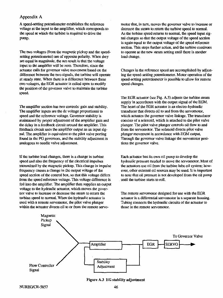
Appendix A A speed-setting potentiometer establishes the reference voltage at the input to the amplifier, which corresponds to the speed at which the turbine is required to drive the pump.
The two voltages (from the magnetic pickup and the speed-setting potentiometer) are of opposite polarity. When they are equal in magnitude, the net result is that the voltage input to the amplifier will be zero. Therefore, since the actuator calls for governor valve movement based on the difference between the two signals, the turbine will operate at steady state. When there is a difference between these two voltages, the EGR actuator is called upon to modify the position of the governor valve to maintain the turbine speed.
The amplifier section has two controls: gain and stability. The amplifier inputs are the dc voltage proportional to speed and the reference voltage. Governor stability is maintained by proper adjustment of the amplifier gain and the delay in a feedback circuit around the amplifier. This feedback circuit uses the amplifier output as an input signal. The amplifier is equivalent to the pilot valve porting found in the PG governors, and the stability adjustment is analogous to needle valve adjustment.
motor that, in turn, moves the governor valve to increase or decrease the steam to return the turbine speed to normal. As the turbine speed returns to normal, the speed input signal changes so that the output voltage of the speed section is again equal to the output voltage of the speed reference section. This stops further action, and the turbine continues to operate at the new steam setting until there is another load change.
Changes in the reference speed are accomplished by adjusting the speed-setting potentiometer. Motor operation of the speed-setting potentiometer is possible to allow for remote speed changes.
The EGR actuator (see Fig. A.3) adjusts the turbine steam supply in accordance with the output signal of the EGM. The heart of the EGR actuator is an electro-hydraulic transducer that directs oil to and from the servomotor, which actuates the governor valve linkage. The transducer consists of a solenoid, which is attached to the pilot valve plunger. The pilot valve plunger controls oil flow to and from the servomotor. The solenoid directs pilot valve plunger movement in accordance with EGM output. Through the governor valve linkage the servomotor positions the governor valve.
If the turbine load changes, there is a change in turbine speed and also the frequency of the electrical impulses transmitted by the magnetic pickup. This change in impulse frequency causes a change in the output voltage of the speed section of the control box, so that this voltage differs from the speed reference voltage. This voltage difference is fed into the amplifier. The amplifier then supplies an output voltage to die hydraulic actuator, which moves me governor valve to increase or decrease the steam to return the turbine speed to normal. When the hydraulic actuator is used with a remote servomotor, die pilot valve plunger within the actuator directs oil to or from the remote servo-
Each actuator has its own oil pump to develop die hydraulic pressure needed to move the servomotor. Most of the actuators use oil from the turbine lube oU system; however, odier external oil sources may be used. It is important to note that oil pressure is not developed from the oil pump until die turbine starts to roll.
The remote servomotor designed for use witii die EGR actuator is a differential servomotor in a separate housing. Tubing connects the hydraulic circuits of the actuator to those in the remote servomotor.
Magnetic Pickup Signal
Flow Controller Signal
Amplifier
Stability Adjustment
To Governor Valve
EGR SERVO
Figure A.3 EG stability adjustment
NUREG/CR-5857 46

EGR actuators provide hydraulic-mechanical steam setting control in response to appropriate electric control signals. The actuators may be adjusted to move toward either minimum or maximum steam in the absence of an electric control signal.
Appendix A
47 NUREG/CR-5857

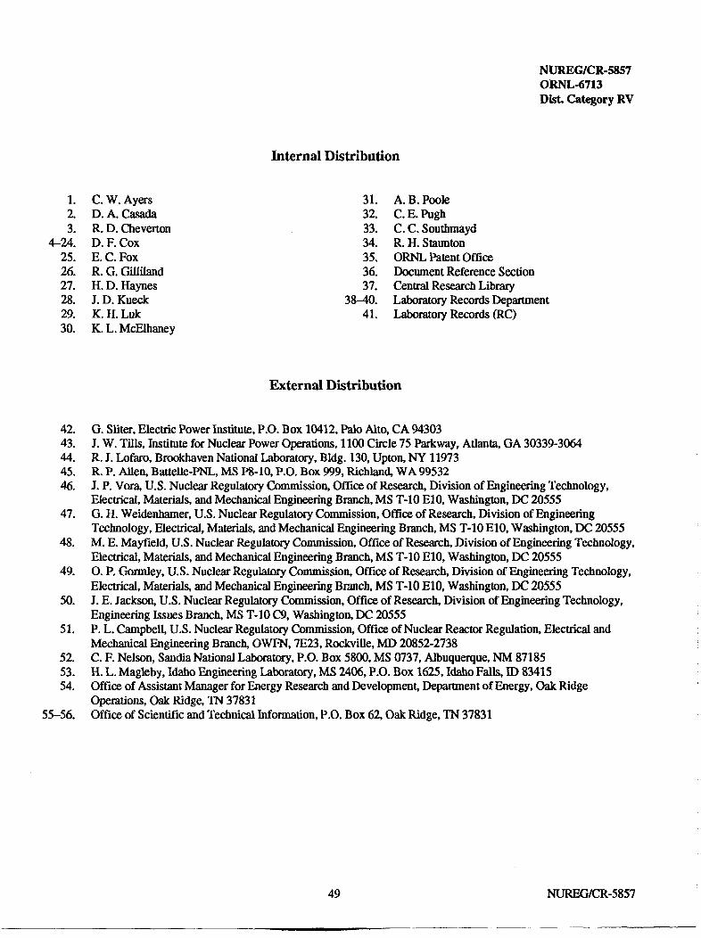
NUREG/CR-5857 ORNL-6713 Disk Category RV
Internal Distribution
*1 C. W. Ayers 2. D. A. Casada 3. R. D. Cheverton
4-24. D. F. Cox 25. E. C. Fox 26. R. G. Gilliland 27. H. D. Haynes 28. J. D. Kueck 29. K. H. Luk 30. K. L. McElhaney
31. A. B. Poole 32. C. E. Pugh 33. C. C. Southmayd 34. R. H. Staunton 35. ORNL Patent Office 36. Document Reference Section 37. Central Research Library
38-40. Laboratory Records Department 41. Laboratory Records (RC)
External Distribution
42. G. Sliter, Electric Power Institute, P.O. Box 10412, Palo Alto, CA 94303 43. J. W. Tills, Institute for Nuclear Power Operations, 1100 Circle 75 Parkway, Atlanta, GA 30339-3064 44. R. J. Lofaro, Brookhaven National Laboratory, Bldg. 130, Upton, NY 11973 45. R. P. Allen, Battelle-PNL, MS P8-10, P.O. Box 999, Richland, WA 99532 46. J. P. Vora, U.S. Nuclear Regulatory Commission, Office of Research, Division of Engineering Technology,
Electrical, Materials, and Mechanical Engineering Branch, MS T-10 E10, Washington, DC 20555 47. G. H. Weidenhamer, U.S. Nuclear Regulatory Commission, Office of Research, Division of Engineering
Technology, Electrical, Materials, and Mechanical Engineering Branch, MS T-10 E10, Washington, DC 20555 48. M. E. Mayfield, U.S. Nuclear Regulatory Commission, Office of Research, Division of Engineering Technology,
Electrical, Materials, and Mechanical Engineering Branch, MS T-10 E10, Washington, DC 20555 49. O. P. Gormley, U.S. Nuclear Regulatory Commission, Office of Research, Division of Engineering Technology,
Electrical, Materials, and Mechanical Engineering Branch, MS T-10 E10, Washington, DC 20555 50. J. E. Jackson, U.S. Nuclear Regulatory Commission, Office of Research, Division of Engineering Technology,
Engineering Issues Branch, MS T-10 C9, Washington, DC 20555 51. P. L. Campbell, U.S. Nuclear Regulatory Commission, Office of Nuclear Reactor Regulation, Electrical and
Mechanical Engineering Branch, OWFN, 7E23, RockviUe, MD 20852-2738 52. C. F. Nelson, Sandia National Laboratory, P.O. Box 5800, MS 0737, Albuquerque, NM 87185 53. H. L. Magleby, Idaho Engineering Laboratory, MS 2406, P.O. Box 1625, Idaho Falls, ID 83415 54. Office of Assistant Manager for Energy Research and Development, Department of Energy, Oak Ridge
Operations, Oak Ridge, TN 37831 55-56. Office of Scientific and Technical Information, P.O. Box 62, Oak Ridge, TN 37831
49 NUREG/CR-5857

NRC FORM 335 U.S. NUCLEAR REGULATORY COMMISSION 12-89) NRCM 1102,
3201.3202 BIBLIOGRAPHIC DATA SHEET (See instructions on the reverse)
1. REPORT NUMBER (Assigned by NRC Add Vol., Supp., Rev., and Addendum Numbers. If any.)
NUREG/CR-5857 ORNL-6713
2. T I T L E A N D SUBTITLE
Aging of Turbine Drives fo r Safety-Related Pumps in Nuclear Power Plants
1. REPORT NUMBER (Assigned by NRC Add Vol., Supp., Rev., and Addendum Numbers. If any.)
NUREG/CR-5857 ORNL-6713
2. T I T L E A N D SUBTITLE
Aging of Turbine Drives fo r Safety-Related Pumps in Nuclear Power Plants 3. DATE REPORT PUBLISHED
2. T I T L E A N D SUBTITLE
Aging of Turbine Drives fo r Safety-Related Pumps in Nuclear Power Plants
, MONTH | - - . T E A R
June 1 1995
2. T I T L E A N D SUBTITLE
Aging of Turbine Drives fo r Safety-Related Pumps in Nuclear Power Plants
4. FIN OR GRANT NUMBER
B0828 5. AUTHOR(S)
D.F. Cox 6. TYPE OF REPORT
Technical 5. AUTHOR(S)
D.F. Cox
7. PERIOD COVERED (Inclusive Dates)
8. PERFORMING ORGANIZATION — NAME A N D ADDRESS (If NRC, provide Division, Office or Region, U.S. Nuclear Regulatory Commission, and mailing address;ifcontractor, provide name and mailing address.}
Oak Ridge National Laboratory Oak Ridge, TN 37831-6285
9. SPONSORING ORGANIZATION - NAME AND ADDRESS (If NRC, type "Same as above"; if contractor, provide NRC Division, Ofi'ice or Region, U.S. Nuclear Regulatory Commission, and mailing address.}
Divis ion of Engineering Technology Off ice of Nuclear Regulatory Research U.S. Nuclear Regulatory Commission Washington, DC 20555-0001
10. SUPPLEMENTARY NOTES
1 1 . ABSTRACT (200 words or less!
This study examines the re la t ionsh ip between aging, and current industry practices in areas of maintenance, surve i l lance, and operation of steam turbine drives for safety re lated pumps. These pumps are located in the Aux i l ia ry Feedwater (AFW) system fo r pressurized water reactor p lan ts , and the Reactor Core Iso la t ion Cooling and High Pressure Coolant In jec t ion systems fo r Boi l ing Water Reactor f a c i l i t i e s . Findings in a recent study on the AFW (NUREG/CR-5404) indicate that the turbine dr ive is the single largest contr ibutor to AFW system degradation. However, examination of the data show that the turbine i t s e l f i s a re l i ab le piece of equipment wi th a good service record. Most of the problems documented are the resu l t of problems with the turbine controls and the mechanical overspeed t r i p mechanism, which apparently stem from three major causes.
12. KEY WORDS/DESCRiPTORS (List wards or phrases that will assist researchers in locating the report.)
Terry tu rb ine , aging, pump d r i ve , service wear, governor
13. AVAILABILITY STATEMENT
unl imited 12. KEY WORDS/DESCRiPTORS (List wards or phrases that will assist researchers in locating the report.)
Terry tu rb ine , aging, pump d r i ve , service wear, governor 14. SECURITY CLASSIFICATION
12. KEY WORDS/DESCRiPTORS (List wards or phrases that will assist researchers in locating the report.)
Terry tu rb ine , aging, pump d r i ve , service wear, governor (This Page)
unclass i f ied
12. KEY WORDS/DESCRiPTORS (List wards or phrases that will assist researchers in locating the report.)
Terry tu rb ine , aging, pump d r i ve , service wear, governor
(This Report)
unclass i f ied
12. KEY WORDS/DESCRiPTORS (List wards or phrases that will assist researchers in locating the report.)
Terry tu rb ine , aging, pump d r i ve , service wear, governor
15. NUMBER OF PAGES
16. PRICE
NRC FORM 335 (2-891