v-can - novastarv-can is a smart control platform for video processors (such as j6, n9) and...
TRANSCRIPT
V-Can
Video Control Software
Document Version: V3.4.0
Document Number: NS160100606
User Manual
http://www.novastar.tech i
Copyright © 2019 Xi’an NovaStar Tech Co., Ltd. All Rights Reserved.
No part of this document may be copied, reproduced, extracted or transmitted in any form or by any means
without the prior written consent of Xi’an NovaStar Tech Co., Ltd.
Trademark
is a trademark of Xi’an NovaStar Tech Co., Ltd.
Statement
You are welcome to use the product of Xi’an NovaStar Tech Co., Ltd. (hereinafter referred to as NovaStar).
This document is intended to help you understand and use the product. For accuracy and reliability,
NovaStar may make improvements and/or changes to this document at any time and without notice. If you
experience any problems in use or have any suggestions, please contact us via contact information given
in document. We will do our best to solve any issues, as well as evaluate and implement any suggestions.
V-Can
User Manual Contents
http://www.novastar.tech ii
Contents
1 Overview ......................................................................................................................................... 1
2 Installation...................................................................................................................................... 2
2.1 Obtaining ................................................................................................................................................. 2
2.2 Installation................................................................................................................................................ 2
2.3 Running ................................................................................................................................................... 2
2.4 User Interface .......................................................................................................................................... 3
3 Functions ......................................................................................................................................... 6
3.1 Choregrapher .......................................................................................................................................... 7
3.1.1 Input ................................................................................................................................................ 8
3.1.1.1 Input ................................................................................................................................... 8
3.1.1.2 Color .................................................................................................................................. 11
3.1.1.3 Hot Backup ....................................................................................................................... 12
3.1.2 Output Settings ............................................................................................................................. 12
3.1.2.1 Output............................................................................................................................... 12
3.1.2.2 Color ................................................................................................................................. 13
3.1.3 System Mode................................................................................................................................ 14
3.1.4 Output Connector Mosaic ............................................................................................................. 15
3.1.5 Image Mosaic ............................................................................................................................... 16
3.1.6 Adding Layers ............................................................................................................................... 18
3.1.7 Setting Layer Properties ............................................................................................................... 20
3.1.8 Effects ........................................................................................................................................... 23
3.1.8.1 Transition Effects .............................................................................................................. 23
3.1.8.2 Take Effects ...................................................................................................................... 24
3.1.9 Duration ........................................................................................................................................ 24
3.1.10 Sync Mode.................................................................................................................................. 25
3.1.11 AUX ............................................................................................................................................. 26
3.1.12 HDR ............................................................................................................................................ 26
3.1.13 Setting Presets ........................................................................................................................... 27
3.1.14 Preset Playing ............................................................................................................................ 30
3.1.15 Output Mapping .......................................................................................................................... 31
3.2 OSD ....................................................................................................................................................... 32
3.2.1 OSD Settings ................................................................................................................................ 32
3.2.2 OSD/BKG Settings ....................................................................................................................... 34
V-Can
User Manual Contents
http://www.novastar.tech iii
3.3 System ................................................................................................................................................... 41
3.3.1 Connecting Device ....................................................................................................................... 42
3.3.2 Synchronization ............................................................................................................................ 42
3.3.3 Firmware Update .......................................................................................................................... 43
3.3.4 Self-Test ........................................................................................................................................ 44
3.3.5 Factory Reset ............................................................................................................................... 45
3.3.6 Network Settings .......................................................................................................................... 45
3.3.7 Language ...................................................................................................................................... 45
V-Can
User Manual 1 Overview
http://www.novastar.tech 1
1 Overview
V-Can is a smart control platform for video processors (such as J6, N9) and all-in-one controllers (such as VX5s, VX6s), allowing users to easily control and manage video processing devices and all-in-one controllers on Windows PC and Mac. When connected with different devices, V-Can offers different user interfaces and functions.
Features:
Easy operation interface
Completely visualized operation platform, easy to use and operate
Applicable systems: Windows and Mac
Capable of connecting multiple video processors and all-in-one controllers
V-Can
User Manual 2 Installation
http://www.novastar.tech 2
2 Installation
2.1 Obtaining
Log into NovaStar official website http://www.novastar.tech to download the appropriate software according to your device and PC system version.
2.2 Installation
Requirements of Software Operating Environment
Processor: CPU: 32/64 bits, 1 GHz or greater
RAM: 2 GB or greater
GPU: DirectX 9 128M and above
HD space: 16 GB or greater
Monitor: Resolution greater than or equal to 1280×720 pixels
OS: Windows 7 or later, MAC OS 10.10 or later
Software Installation
Just like the installation of other common software, follow the setup wizard to install V-Can.
2.3 Running
After successful installation, double click on the desktop to run V-Can. The main user interface for V-Can is shown in Figure 2-1.
V-Can
User Manual 2 Installation
http://www.novastar.tech 3
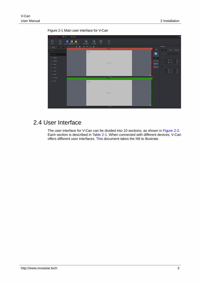
Figure 2-1 Main user interface for V-Can
2.4 User Interface
The user interface for V-Can can be divided into 10 sections, as shown in Figure 2-2. Each section is described in Table 2-1. When connected with different devices, V-Can offers different user interfaces. This document takes the N9 to illustrate.
V-Can
User Manual 2 Installation
http://www.novastar.tech 4
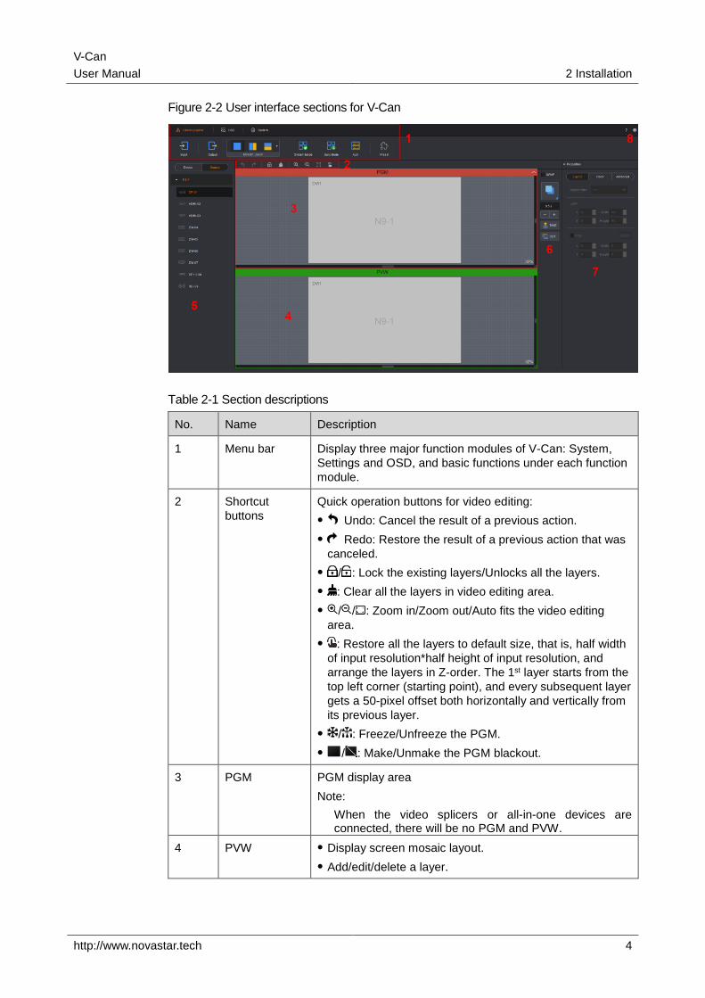
Figure 2-2 User interface sections for V-Can
Table 2-1 Section descriptions
No. Name Description
1 Menu bar Display three major function modules of V-Can: System,
Settings and OSD, and basic functions under each function
module.
2 Shortcut
buttons
Quick operation buttons for video editing:
Undo: Cancel the result of a previous action.
Redo: Restore the result of a previous action that was
canceled.
/ : Lock the existing layers/Unlocks all the layers.
: Clear all the layers in video editing area.
/ / : Zoom in/Zoom out/Auto fits the video editing
area.
: Restore all the layers to default size, that is, half width
of input resolution*half height of input resolution, and
arrange the layers in Z-order. The 1st layer starts from the
top left corner (starting point), and every subsequent layer
gets a 50-pixel offset both horizontally and vertically from
its previous layer.
/ : Freeze/Unfreeze the PGM.
/ : Make/Unmake the PGM blackout.
3 PGM PGM display area
Note:
When the video splicers or all-in-one devices are connected, there will be no PGM and PVW.
4 PVW Display screen mosaic layout.
Add/edit/delete a layer.
V-Can
User Manual 2 Installation
http://www.novastar.tech 5
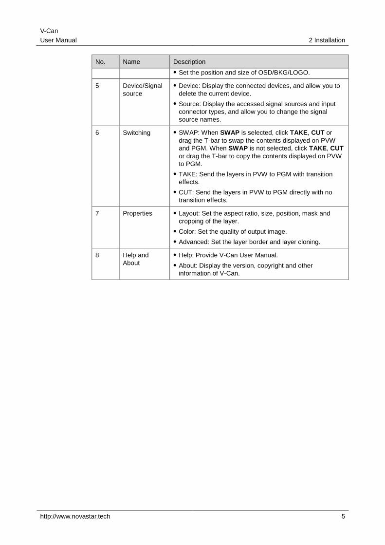
No. Name Description
Set the position and size of OSD/BKG/LOGO.
5 Device/Signal
source
Device: Display the connected devices, and allow you to
delete the current device.
Source: Display the accessed signal sources and input
connector types, and allow you to change the signal
source names.
6 Switching SWAP: When SWAP is selected, click TAKE, CUT or
drag the T-bar to swap the contents displayed on PVW
and PGM. When SWAP is not selected, click TAKE, CUT
or drag the T-bar to copy the contents displayed on PVW
to PGM.
TAKE: Send the layers in PVW to PGM with transition
effects.
CUT: Send the layers in PVW to PGM directly with no
transition effects.
7 Properties Layout: Set the aspect ratio, size, position, mask and
cropping of the layer.
Color: Set the quality of output image.
Advanced: Set the layer border and layer cloning.
8 Help and
About
Help: Provide V-Can User Manual.
About: Display the version, copyright and other
information of V-Can.
V-Can
User Manual 3 Functions
http://www.novastar.tech 6
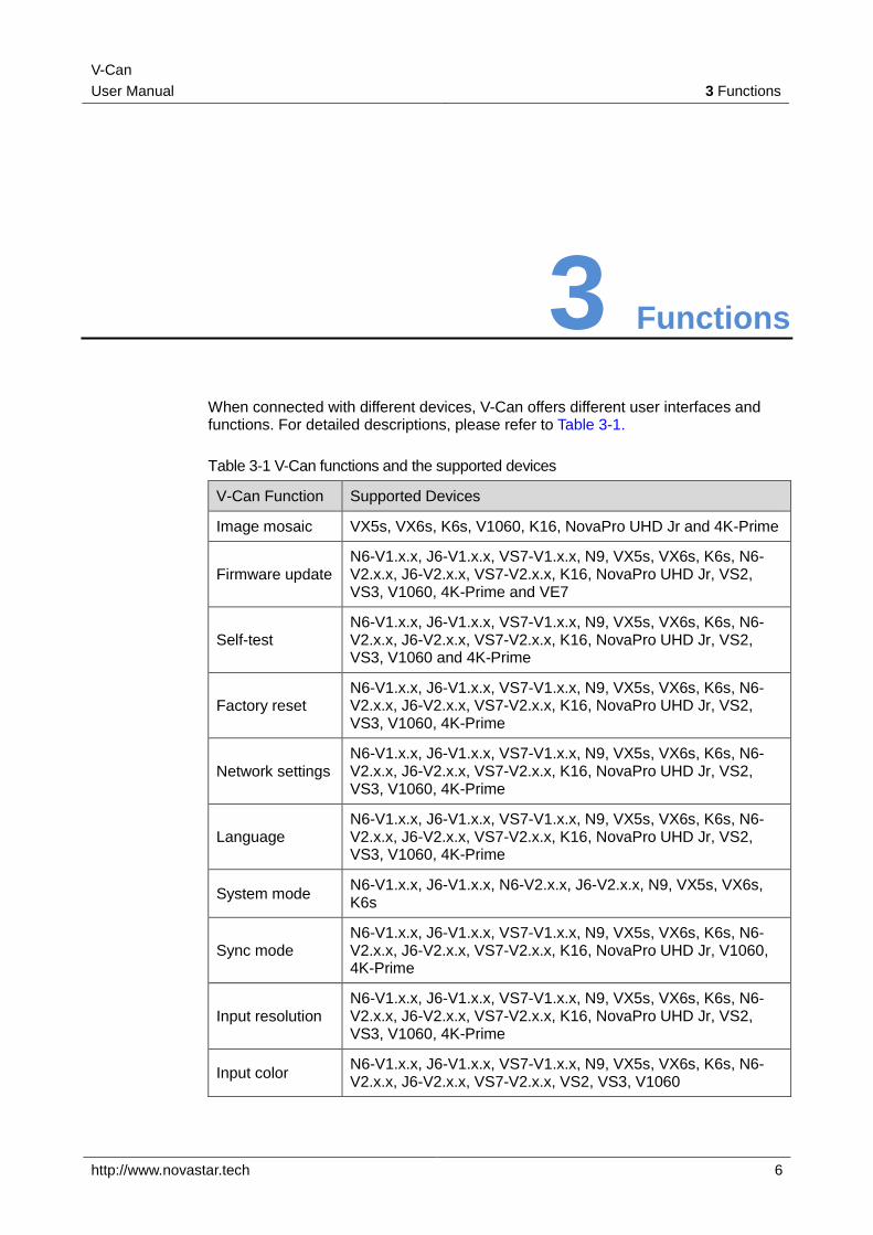
3 Functions
When connected with different devices, V-Can offers different user interfaces and functions. For detailed descriptions, please refer to Table 3-1.
Table 3-1 V-Can functions and the supported devices
V-Can Function Supported Devices
Image mosaic VX5s, VX6s, K6s, V1060, K16, NovaPro UHD Jr and 4K-Prime
Firmware update N6-V1.x.x, J6-V1.x.x, VS7-V1.x.x, N9, VX5s, VX6s, K6s, N6-V2.x.x, J6-V2.x.x, VS7-V2.x.x, K16, NovaPro UHD Jr, VS2, VS3, V1060, 4K-Prime and VE7
Self-test N6-V1.x.x, J6-V1.x.x, VS7-V1.x.x, N9, VX5s, VX6s, K6s, N6-V2.x.x, J6-V2.x.x, VS7-V2.x.x, K16, NovaPro UHD Jr, VS2, VS3, V1060 and 4K-Prime
Factory reset N6-V1.x.x, J6-V1.x.x, VS7-V1.x.x, N9, VX5s, VX6s, K6s, N6-V2.x.x, J6-V2.x.x, VS7-V2.x.x, K16, NovaPro UHD Jr, VS2, VS3, V1060, 4K-Prime
Network settings N6-V1.x.x, J6-V1.x.x, VS7-V1.x.x, N9, VX5s, VX6s, K6s, N6-V2.x.x, J6-V2.x.x, VS7-V2.x.x, K16, NovaPro UHD Jr, VS2, VS3, V1060, 4K-Prime
Language N6-V1.x.x, J6-V1.x.x, VS7-V1.x.x, N9, VX5s, VX6s, K6s, N6-V2.x.x, J6-V2.x.x, VS7-V2.x.x, K16, NovaPro UHD Jr, VS2, VS3, V1060, 4K-Prime
System mode N6-V1.x.x, J6-V1.x.x, N6-V2.x.x, J6-V2.x.x, N9, VX5s, VX6s, K6s
Sync mode N6-V1.x.x, J6-V1.x.x, VS7-V1.x.x, N9, VX5s, VX6s, K6s, N6-V2.x.x, J6-V2.x.x, VS7-V2.x.x, K16, NovaPro UHD Jr, V1060, 4K-Prime
Input resolution N6-V1.x.x, J6-V1.x.x, VS7-V1.x.x, N9, VX5s, VX6s, K6s, N6-V2.x.x, J6-V2.x.x, VS7-V2.x.x, K16, NovaPro UHD Jr, VS2, VS3, V1060, 4K-Prime
Input color N6-V1.x.x, J6-V1.x.x, VS7-V1.x.x, N9, VX5s, VX6s, K6s, N6-V2.x.x, J6-V2.x.x, VS7-V2.x.x, VS2, VS3, V1060
V-Can
User Manual 3 Functions
http://www.novastar.tech 7
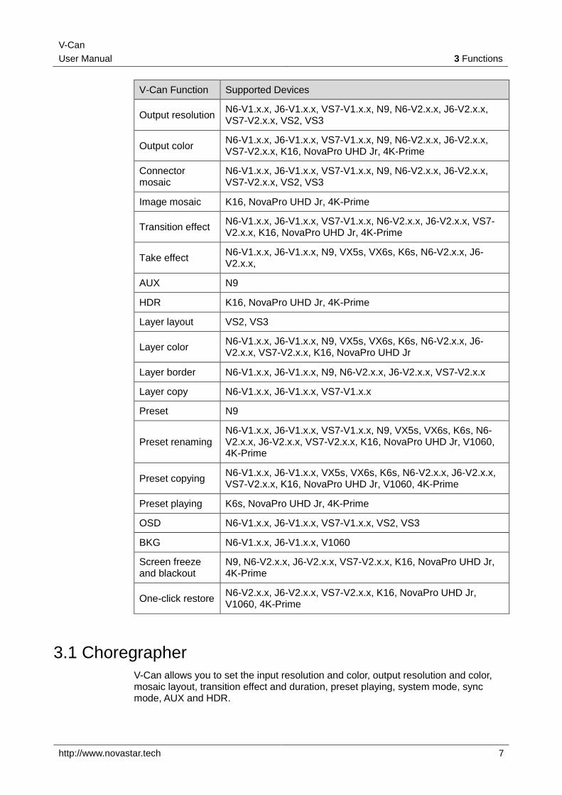
V-Can Function Supported Devices
Output resolution N6-V1.x.x, J6-V1.x.x, VS7-V1.x.x, N9, N6-V2.x.x, J6-V2.x.x, VS7-V2.x.x, VS2, VS3
Output color N6-V1.x.x, J6-V1.x.x, VS7-V1.x.x, N9, N6-V2.x.x, J6-V2.x.x, VS7-V2.x.x, K16, NovaPro UHD Jr, 4K-Prime
Connector mosaic
N6-V1.x.x, J6-V1.x.x, VS7-V1.x.x, N9, N6-V2.x.x, J6-V2.x.x, VS7-V2.x.x, VS2, VS3
Image mosaic K16, NovaPro UHD Jr, 4K-Prime
Transition effect N6-V1.x.x, J6-V1.x.x, VS7-V1.x.x, N6-V2.x.x, J6-V2.x.x, VS7-V2.x.x, K16, NovaPro UHD Jr, 4K-Prime
Take effect N6-V1.x.x, J6-V1.x.x, N9, VX5s, VX6s, K6s, N6-V2.x.x, J6-V2.x.x,
AUX N9
HDR K16, NovaPro UHD Jr, 4K-Prime
Layer layout VS2, VS3
Layer color N6-V1.x.x, J6-V1.x.x, N9, VX5s, VX6s, K6s, N6-V2.x.x, J6-V2.x.x, VS7-V2.x.x, K16, NovaPro UHD Jr
Layer border N6-V1.x.x, J6-V1.x.x, N9, N6-V2.x.x, J6-V2.x.x, VS7-V2.x.x
Layer copy N6-V1.x.x, J6-V1.x.x, VS7-V1.x.x
Preset N9
Preset renaming N6-V1.x.x, J6-V1.x.x, VS7-V1.x.x, N9, VX5s, VX6s, K6s, N6-V2.x.x, J6-V2.x.x, VS7-V2.x.x, K16, NovaPro UHD Jr, V1060, 4K-Prime
Preset copying N6-V1.x.x, J6-V1.x.x, VX5s, VX6s, K6s, N6-V2.x.x, J6-V2.x.x, VS7-V2.x.x, K16, NovaPro UHD Jr, V1060, 4K-Prime
Preset playing K6s, NovaPro UHD Jr, 4K-Prime
OSD N6-V1.x.x, J6-V1.x.x, VS7-V1.x.x, VS2, VS3
BKG N6-V1.x.x, J6-V1.x.x, V1060
Screen freeze and blackout
N9, N6-V2.x.x, J6-V2.x.x, VS7-V2.x.x, K16, NovaPro UHD Jr, 4K-Prime
One-click restore N6-V2.x.x, J6-V2.x.x, VS7-V2.x.x, K16, NovaPro UHD Jr, V1060, 4K-Prime
3.1 Choregrapher
V-Can allows you to set the input resolution and color, output resolution and color, mosaic layout, transition effect and duration, preset playing, system mode, sync mode, AUX and HDR.
V-Can
User Manual 3 Functions
http://www.novastar.tech 8
3.1.1 Input
3.1.1.1 Input
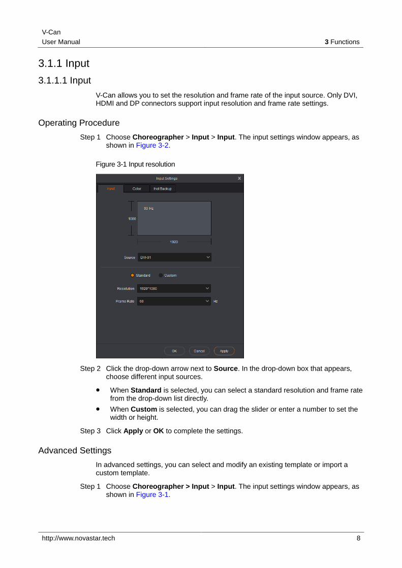
V-Can allows you to set the resolution and frame rate of the input source. Only DVI, HDMI and DP connectors support input resolution and frame rate settings.
Operating Procedure
Step 1 Choose Choreographer > Input > Input. The input settings window appears, as shown in Figure 3-2.
Figure 3-1 Input resolution
Step 2 Click the drop-down arrow next to Source. In the drop-down box that appears, choose different input sources.
When Standard is selected, you can select a standard resolution and frame rate from the drop-down list directly.
When Custom is selected, you can drag the slider or enter a number to set the width or height.
Step 3 Click Apply or OK to complete the settings.
Advanced Settings
In advanced settings, you can select and modify an existing template or import a custom template.
Step 1 Choose Choreographer > Input > Input. The input settings window appears, as shown in Figure 3-1.
V-Can
User Manual 3 Functions
http://www.novastar.tech 9
Step 2 Select Custom.
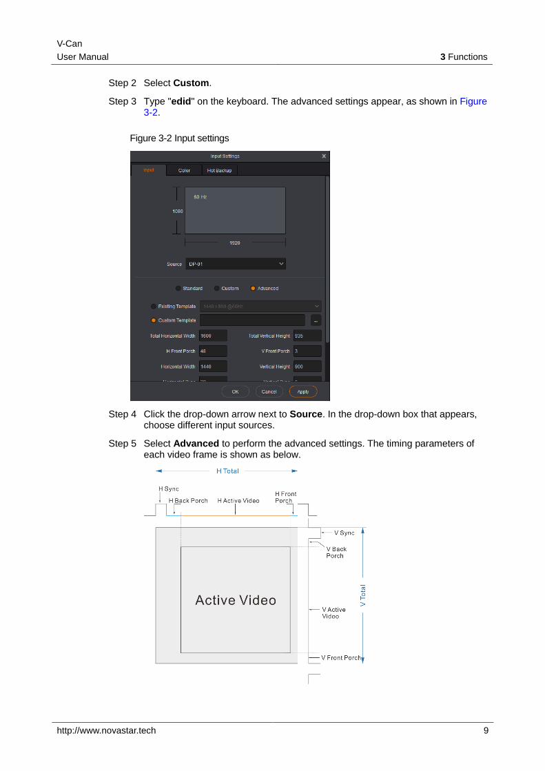
Step 3 Type "edid" on the keyboard. The advanced settings appear, as shown in Figure 3-2.
Figure 3-2 Input settings
Step 4 Click the drop-down arrow next to Source. In the drop-down box that appears, choose different input sources.
Step 5 Select Advanced to perform the advanced settings. The timing parameters of each video frame is shown as below.
V-Can
User Manual 3 Functions
http://www.novastar.tech 10
Step 6 When Existing Template is selected, you can select and modify an existing template. When Custom Template is selected, you can import a custom template.
If you need to modify the template parameters, you can contact NovaStar for technical support.
Input Mosaic
The NovaPro UHD Jr and 4K-Prime support the DVI mosaic function. A maximum of four 4 DVI inputs can be used to form one input source.
The procedure is described as below.
Step 1 Choose Choreographer > Input to enter the input settings screen.
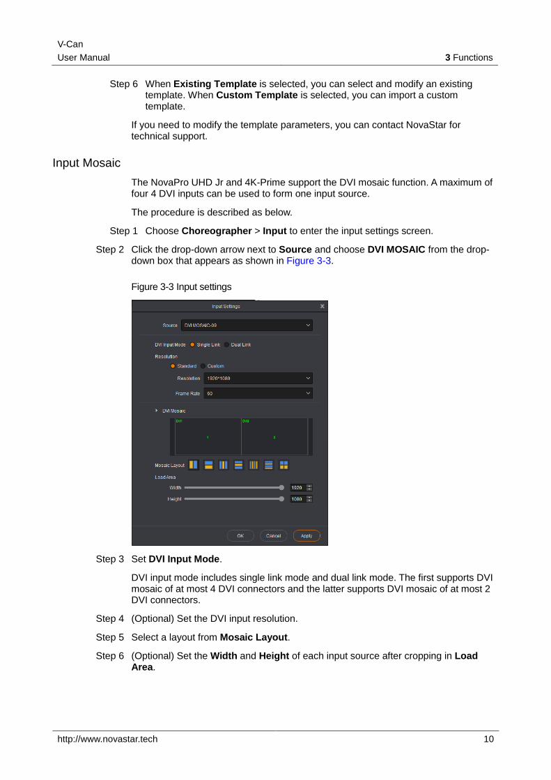
Step 2 Click the drop-down arrow next to Source and choose DVI MOSAIC from the drop-down box that appears as shown in Figure 3-3.
Figure 3-3 Input settings
Step 3 Set DVI Input Mode.
DVI input mode includes single link mode and dual link mode. The first supports DVI mosaic of at most 4 DVI connectors and the latter supports DVI mosaic of at most 2 DVI connectors.
Step 4 (Optional) Set the DVI input resolution.
Step 5 Select a layout from Mosaic Layout.
Step 6 (Optional) Set the Width and Height of each input source after cropping in Load Area.
V-Can
User Manual 3 Functions
http://www.novastar.tech 11
Note:
The starting point of input source cropping is the top left corner.
3.1.1.2 Color
V-Can allows you to set the brightness, contrast, hue, saturation and Gamma of the input source accessed to each device.
Note:
When the connected device is the NovaPro UHD Jr or 4K-Prime, input color settings are not supported.
Operating Procedure
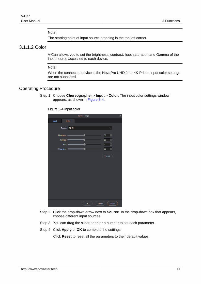
Step 1 Choose Choreographer > Input > Color. The input color settings window appears, as shown in Figure 3-4.
Figure 3-4 Input color
Step 2 Click the drop-down arrow next to Source. In the drop-down box that appears, choose different input sources.
Step 3 You can drag the slider or enter a number to set each parameter.
Step 4 Click Apply or OK to complete the settings.
Click Reset to reset all the parameters to their default values.
V-Can
User Manual 3 Functions
http://www.novastar.tech 12
3.1.1.3 Hot Backup
V-Can allows you set input backup channels in case of input connector failures. When fault occurs on input connector, the backup channel can be a timely alternative to avoid black screen and other display abnormalities.
When the connected device is the N6, J6 or VS7 V1.x.x, this function is not supported.
Operating Procedure
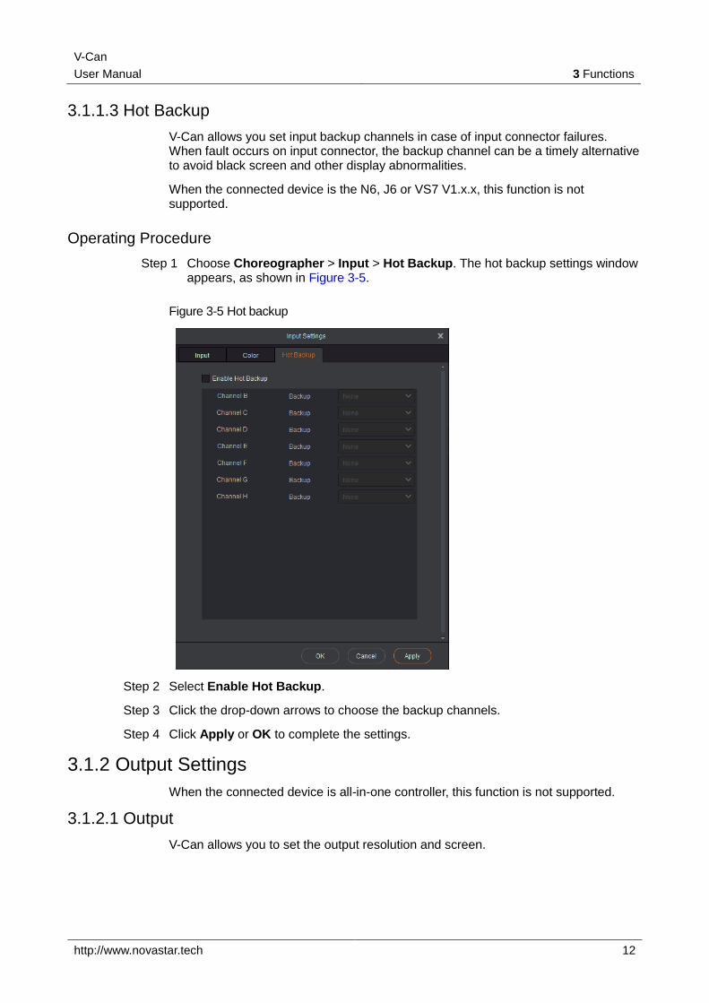
Step 1 Choose Choreographer > Input > Hot Backup. The hot backup settings window appears, as shown in Figure 3-5.
Figure 3-5 Hot backup
Step 2 Select Enable Hot Backup.
Step 3 Click the drop-down arrows to choose the backup channels.
Step 4 Click Apply or OK to complete the settings.
3.1.2 Output Settings
When the connected device is all-in-one controller, this function is not supported.
3.1.2.1 Output
V-Can allows you to set the output resolution and screen.
V-Can
User Manual 3 Functions
http://www.novastar.tech 13
Operating Procedure
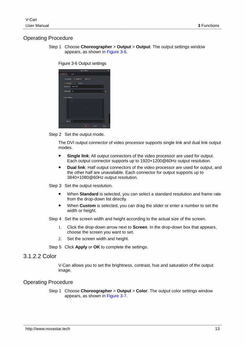
Step 1 Choose Choreographer > Output > Output. The output settings window appears, as shown in Figure 3-6.
Figure 3-6 Output settings
Step 2 Set the output mode.
The DVI output connector of video processor supports single link and dual link output modes.
Single link: All output connectors of the video processor are used for output. Each output connector supports up to 1920×1200@60Hz output resolution.
Dual link: Half output connectors of the video processor are used for output, and the other half are unavailable. Each connector for output supports up to 3840×1080@60Hz output resolution.
Step 3 Set the output resolution.
When Standard is selected, you can select a standard resolution and frame rate from the drop-down list directly.
When Custom is selected, you can drag the slider or enter a number to set the width or height.
Step 4 Set the screen width and height according to the actual size of the screen.
1. Click the drop-down arrow next to Screen. In the drop-down box that appears, choose the screen you want to set.
2. Set the screen width and height.
Step 5 Click Apply or OK to complete the settings.
3.1.2.2 Color
V-Can allows you to set the brightness, contrast, hue and saturation of the output image.
Operating Procedure
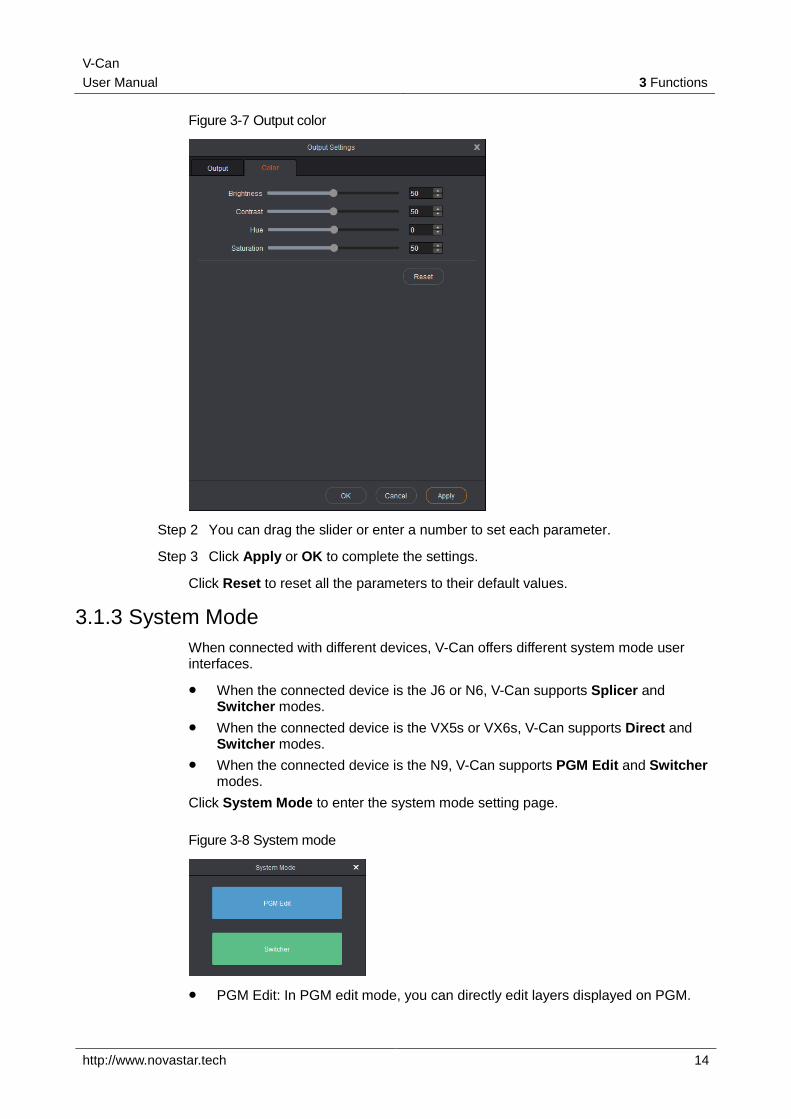
Step 1 Choose Choreographer > Output > Color. The output color settings window appears, as shown in Figure 3-7.
V-Can
User Manual 3 Functions
http://www.novastar.tech 14
Figure 3-7 Output color
Step 2 You can drag the slider or enter a number to set each parameter.
Step 3 Click Apply or OK to complete the settings.
Click Reset to reset all the parameters to their default values.
3.1.3 System Mode
When connected with different devices, V-Can offers different system mode user interfaces.
When the connected device is the J6 or N6, V-Can supports Splicer and Switcher modes.
When the connected device is the VX5s or VX6s, V-Can supports Direct and Switcher modes.
When the connected device is the N9, V-Can supports PGM Edit and Switcher modes.
Click System Mode to enter the system mode setting page.
Figure 3-8 System mode
PGM Edit: In PGM edit mode, you can directly edit layers displayed on PGM.
V-Can
User Manual 3 Functions
http://www.novastar.tech 15
Splicer/Direct: In splicer or direct mode, your settings on the layer will be synchronously displayed on the LED screen.
Switcher: In switcher mode, you can add and edit layer information only in PVW area. After the layer information is edited, click Take at the top right to send the edited layer to the LED screen.
Operating Procedure
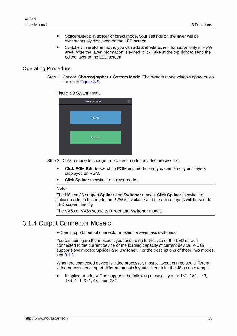
Step 1 Choose Choreographer > System Mode. The system mode window appears, as shown in Figure 3-9.
Figure 3-9 System mode
Step 2 Click a mode to change the system mode for video processors.
Click PGM Edit to switch to PGM edit mode, and you can directly edit layers displayed on PGM.
Click Splicer to switch to splicer mode.
Note:
The N6 and J6 support Splicer and Switcher modes. Click Splicer to switch to splicer mode. In this mode, no PVW is available and the edited layers will be sent to LED screen directly.
The VX5s or VX6s supports Direct and Switcher modes.
3.1.4 Output Connector Mosaic
V-Can supports output connector mosaic for seamless switchers.
You can configure the mosaic layout according to the size of the LED screen connected to the current device or the loading capacity of current device. V-Can supports two modes: Splicer and Switcher. For the descriptions of these two modes, see 3.1.3 .
When the connected device is video processor, mosaic layout can be set. Different video processors support different mosaic layouts. Here take the J6 as an example.
In splicer mode, V-Can supports the following mosaic layouts: 1×1, 1×2, 1×3, 1×4, 2×1, 3×1, 4×1 and 2×2.
V-Can
User Manual 3 Functions
http://www.novastar.tech 16
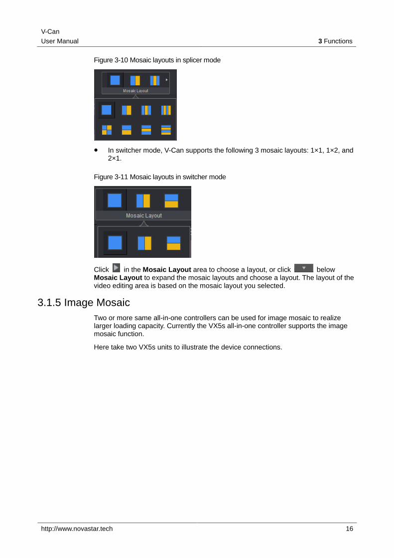
Figure 3-10 Mosaic layouts in splicer mode
In switcher mode, V-Can supports the following 3 mosaic layouts: 1×1, 1×2, and 2×1.
Figure 3-11 Mosaic layouts in switcher mode
Click in the Mosaic Layout area to choose a layout, or click below Mosaic Layout to expand the mosaic layouts and choose a layout. The layout of the video editing area is based on the mosaic layout you selected.
3.1.5 Image Mosaic
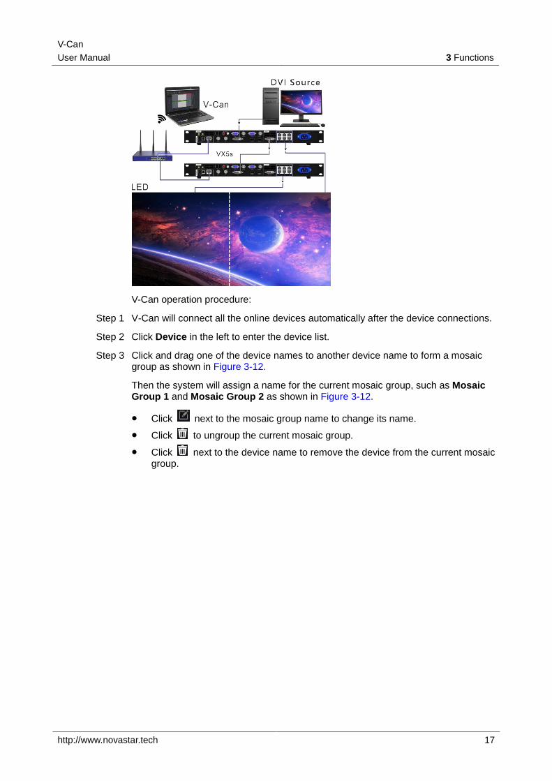
Two or more same all-in-one controllers can be used for image mosaic to realize larger loading capacity. Currently the VX5s all-in-one controller supports the image mosaic function.
Here take two VX5s units to illustrate the device connections.
V-Can
User Manual 3 Functions
http://www.novastar.tech 17
V-Can operation procedure:
Step 1 V-Can will connect all the online devices automatically after the device connections.
Step 2 Click Device in the left to enter the device list.
Step 3 Click and drag one of the device names to another device name to form a mosaic group as shown in Figure 3-12.
Then the system will assign a name for the current mosaic group, such as Mosaic Group 1 and Mosaic Group 2 as shown in Figure 3-12.
Click next to the mosaic group name to change its name.
Click to ungroup the current mosaic group.
Click next to the device name to remove the device from the current mosaic group.
V-Can
User Manual 3 Functions
http://www.novastar.tech 18
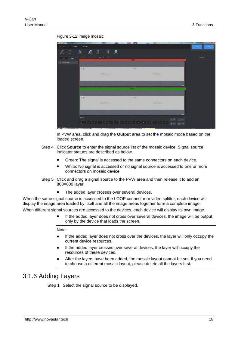
Figure 3-12 Image mosaic
In PVW area, click and drag the Output area to set the mosaic mode based on the loaded screen.
Step 4 Click Source to enter the signal source list of the mosaic device. Signal source indicator statues are described as below.
Green: The signal is accessed to the same connectors on each device.
White: No signal is accessed or no signal source is accessed to one or more connectors on mosaic device.
Step 5 Click and drag a signal source to the PVW area and then release it to add an 800×600 layer.
The added layer crosses over several devices.
When the same signal source is accessed to the LOOP connector or video splitter, each device will display the image area loaded by itself and all the image areas together form a complete image.
When different signal sources are accessed to the devices, each device will display its own image.
If the added layer does not cross over several devices, the image will be output only by the device that loads the screen.
Note:
If the added layer does not cross over the devices, the layer will only occupy the current device resources.
If the added layer crosses over several devices, the layer will occupy the resources of these devices.
After the layers have been added, the mosaic layout cannot be set. If you need to choose a different mosaic layout, please delete all the layers first.
3.1.6 Adding Layers
Step 1 Select the signal source to be displayed.
V-Can
User Manual 3 Functions
http://www.novastar.tech 19
Step 2 In video editing area, press and hold down the left mouse button, move the mouse to the video editing area and then release the left mouse button. A custom-sized layer appears.
On a signal source, press and hold down the left mouse button, drag the source to the video editing area, and then release the left mouse button. A layer appears.
Note:
For online devices, the resolution of the newly-added layer is the half of the input source resolution. For example, if the input source resolution is 1920×1080, the resolution of the new layer is 960×540 by default.
If the input source resolution is smaller than 800×600, the resolution of the new layer is 800×600 by default.
For offline devices, the resolution of the new layer is 800×600 by default.
Layer
Hover the mouse over the edge of a layer. When the mouse pointer changes into a double arrow, press and hold down the left mouse button, move the mouse to adjust the size of the layer.
Move the mouse within a layer, press and hold down the left mouse button, drag the layer to move it to any position.
When you hover the mouse over the layer, four buttons appear at the top right of the layer. The functions of the buttons are shown in Table 3-2.
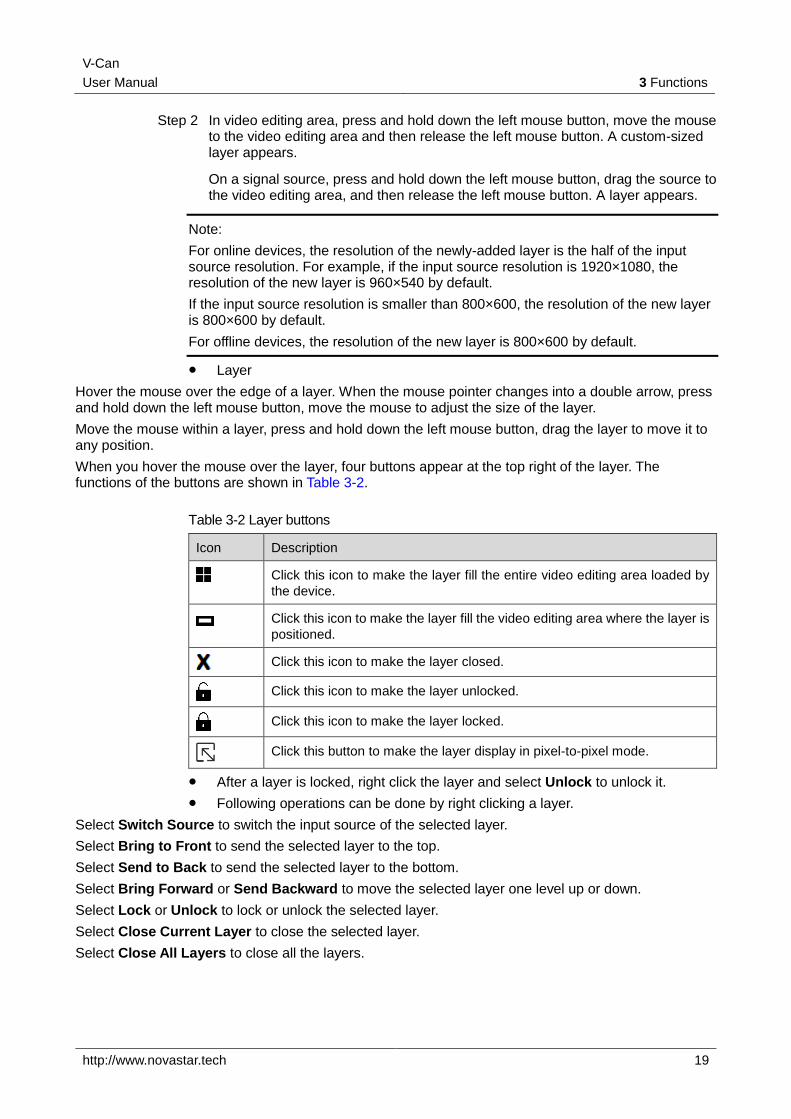
Table 3-2 Layer buttons
Icon Description
Click this icon to make the layer fill the entire video editing area loaded by
the device.
Click this icon to make the layer fill the video editing area where the layer is
positioned.
Click this icon to make the layer closed.
Click this icon to make the layer unlocked.
Click this icon to make the layer locked.
Click this button to make the layer display in pixel-to-pixel mode.
After a layer is locked, right click the layer and select Unlock to unlock it.
Following operations can be done by right clicking a layer.
Select Switch Source to switch the input source of the selected layer.
Select Bring to Front to send the selected layer to the top.
Select Send to Back to send the selected layer to the bottom.
Select Bring Forward or Send Backward to move the selected layer one level up or down.
Select Lock or Unlock to lock or unlock the selected layer.
Select Close Current Layer to close the selected layer.
Select Close All Layers to close all the layers.
V-Can
User Manual 3 Functions
http://www.novastar.tech 20
3.1.7 Setting Layer Properties
BKG does not support property settings and OSD only supports position adjustment.
Layout
In Layout settings page, you can set the aspect ratio, position and size of a layer, as well as crop the input source of the selected layer.
Step 1 Click to select the layer you want to set.
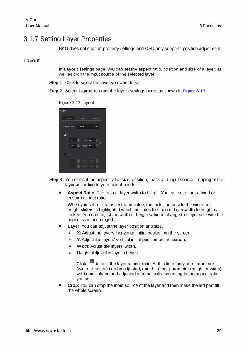
Step 2 Select Layout to enter the layout settings page, as shown in Figure 3-13.
Figure 3-13 Layout
Step 3 You can set the aspect ratio, size, position, mask and input source cropping of the layer according to your actual needs.
Aspect Ratio: The ratio of layer width to height. You can set either a fixed or custom aspect ratio.
When you set a fixed aspect ratio value, the lock icon beside the width and height sliders is highlighted which indicates the ratio of layer width to height is locked. You can adjust the width or height value to change the layer size with the aspect ratio unchanged.
Layer: You can adjust the layer position and size.
X: Adjust the layers' horizontal initial position on the screen.
Y: Adjust the layers' vertical initial position on the screen.
Width: Adjust the layers' width.
Height: Adjust the layer's height.
Click to lock the layer aspect ratio. At this time, only one parameter (width or height) can be adjusted, and the other parameter (height or width) will be calculated and adjusted automatically according to the aspect ratio you set.
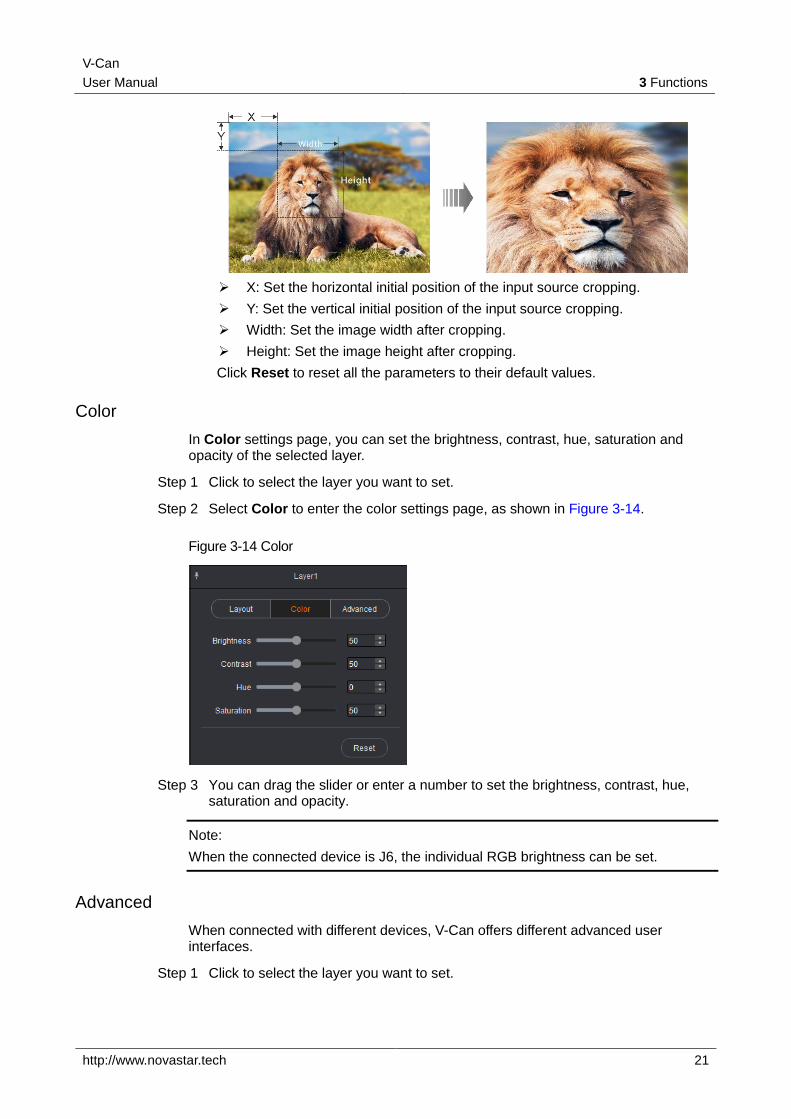
Crop: You can crop the input source of the layer and then make the left part fill the whole screen.
V-Can
User Manual 3 Functions
http://www.novastar.tech 21
X: Set the horizontal initial position of the input source cropping.
Y: Set the vertical initial position of the input source cropping.
Width: Set the image width after cropping.
Height: Set the image height after cropping.
Click Reset to reset all the parameters to their default values.
Color
In Color settings page, you can set the brightness, contrast, hue, saturation and opacity of the selected layer.
Step 1 Click to select the layer you want to set.
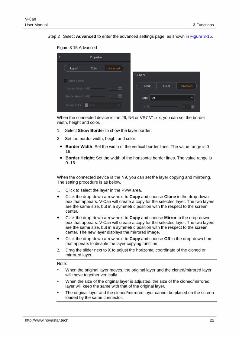
Step 2 Select Color to enter the color settings page, as shown in Figure 3-14.
Figure 3-14 Color
Step 3 You can drag the slider or enter a number to set the brightness, contrast, hue, saturation and opacity.
Note:
When the connected device is J6, the individual RGB brightness can be set.
Advanced
When connected with different devices, V-Can offers different advanced user interfaces.
Step 1 Click to select the layer you want to set.
V-Can
User Manual 3 Functions
http://www.novastar.tech 22
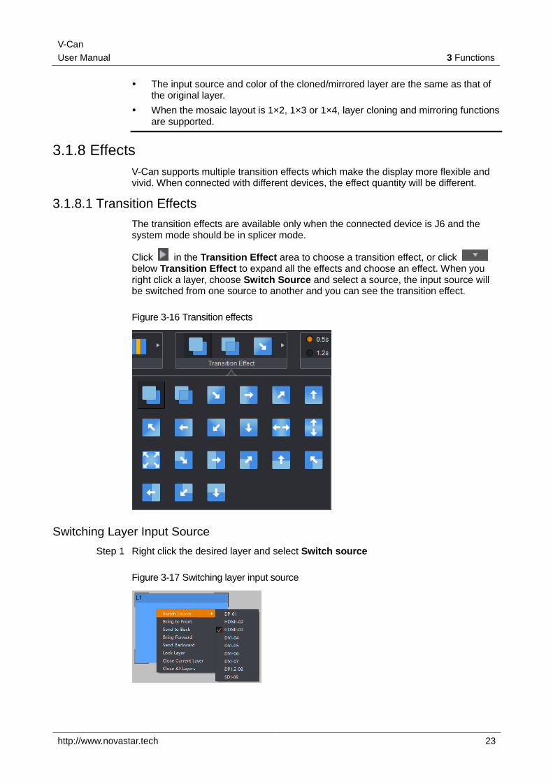
Step 2 Select Advanced to enter the advanced settings page, as shown in Figure 3-15.
Figure 3-15 Advanced
When the connected device is the J6, N6 or VS7 V1.x.x, you can set the border width, height and color.
1. Select Show Border to show the layer border.
2. Set the border width, height and color.
Border Width: Set the width of the vertical border lines. The value range is 0–16.
Border Height: Set the width of the horizontal border lines. The value range is 0–16.
When the connected device is the N9, you can set the layer copying and mirroring. The setting procedure is as below.
1. Click to select the layer in the PVW area.
Click the drop-down arrow next to Copy and choose Clone in the drop-down box that appears. V-Can will create a copy for the selected layer. The two layers are the same size, but in a symmetric position with the respect to the screen center.
Click the drop-down arrow next to Copy and choose Mirror in the drop-down box that appears. V-Can will create a copy for the selected layer. The two layers are the same size, but in a symmetric position with the respect to the screen center. The new layer displays the mirrored image.
Click the drop-down arrow next to Copy and choose Off in the drop-down box that appears to disable the layer copying function.
2. Drag the slider next to X to adjust the horizontal coordinate of the cloned or mirrored layer.
Note:
When the original layer moves, the original layer and the cloned/mirrored layer will move together vertically.
When the size of the original layer is adjusted, the size of the cloned/mirrored layer will keep the same with that of the original layer.
The original layer and the cloned/mirrored layer cannot be placed on the screen loaded by the same connector.
V-Can
User Manual 3 Functions
http://www.novastar.tech 23
The input source and color of the cloned/mirrored layer are the same as that of the original layer.
When the mosaic layout is 1×2, 1×3 or 1×4, layer cloning and mirroring functions are supported.
3.1.8 Effects
V-Can supports multiple transition effects which make the display more flexible and vivid. When connected with different devices, the effect quantity will be different.
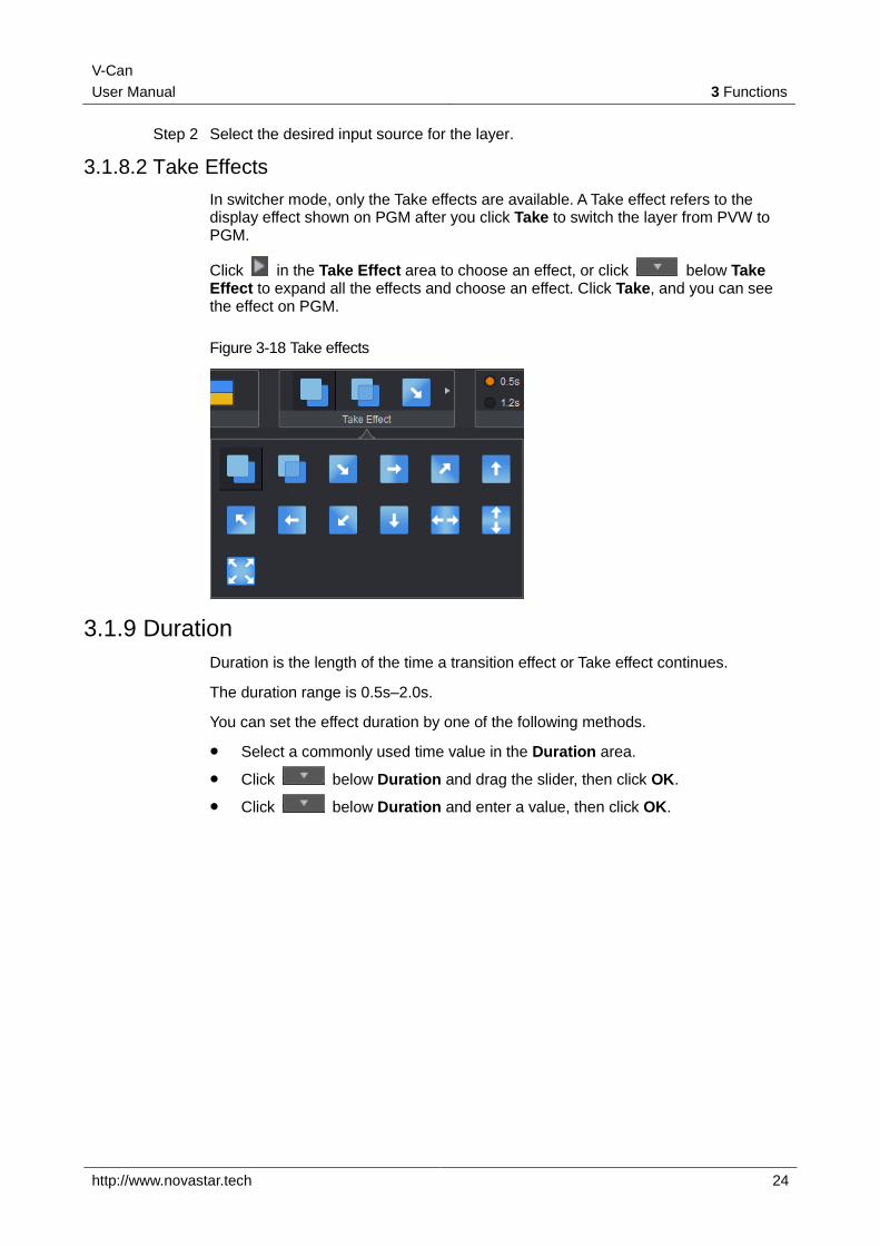
3.1.8.1 Transition Effects
The transition effects are available only when the connected device is J6 and the system mode should be in splicer mode.
Click in the Transition Effect area to choose a transition effect, or click below Transition Effect to expand all the effects and choose an effect. When you right click a layer, choose Switch Source and select a source, the input source will be switched from one source to another and you can see the transition effect.
Figure 3-16 Transition effects
Switching Layer Input Source
Step 1 Right click the desired layer and select Switch source
Figure 3-17 Switching layer input source
V-Can
User Manual 3 Functions
http://www.novastar.tech 24
Step 2 Select the desired input source for the layer.
3.1.8.2 Take Effects
In switcher mode, only the Take effects are available. A Take effect refers to the display effect shown on PGM after you click Take to switch the layer from PVW to PGM.
Click in the Take Effect area to choose an effect, or click below Take Effect to expand all the effects and choose an effect. Click Take, and you can see the effect on PGM.
Figure 3-18 Take effects
3.1.9 Duration
Duration is the length of the time a transition effect or Take effect continues.
The duration range is 0.5s–2.0s.
You can set the effect duration by one of the following methods.
Select a commonly used time value in the Duration area.
Click below Duration and drag the slider, then click OK.
Click below Duration and enter a value, then click OK.
V-Can
User Manual 3 Functions
http://www.novastar.tech 25
Figure 3-19 Duration
Note:
If the connected device is VX5s or VX6s, the duration includes six levels. When the duration is set to 1, the effect duration is the shortest. When the duration is set to 6, the effect duration is the longest. Rather than adjust the duration freely, you can only choose an existing duration.
3.1.10 Sync Mode
When multiple devices are cascaded, the sync mode must be enabled. Synchronization between signal sources makes sure the display of the mosaic screen is intact and consistent.
When devices such as cameras are connected, enabling sync mode can remove scan lines.
Operating Procedure
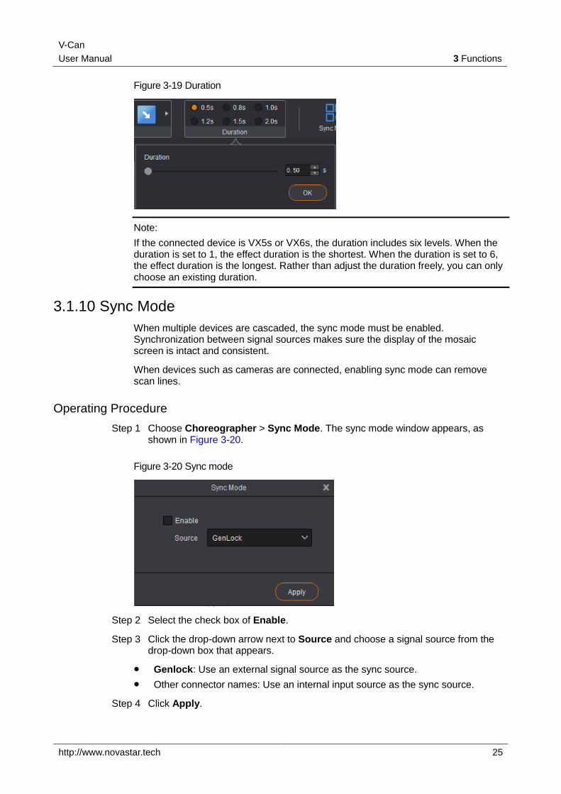
Step 1 Choose Choreographer > Sync Mode. The sync mode window appears, as shown in Figure 3-20.
Figure 3-20 Sync mode
Step 2 Select the check box of Enable.
Step 3 Click the drop-down arrow next to Source and choose a signal source from the drop-down box that appears.
Genlock: Use an external signal source as the sync source.
Other connector names: Use an internal input source as the sync source.
Step 4 Click Apply.
V-Can
User Manual 3 Functions
http://www.novastar.tech 26
3.1.11 AUX
When the connected device supports auxiliary output function, you can set the input source of the aux output via V-Can. Currently the N9 supports AUX settings.
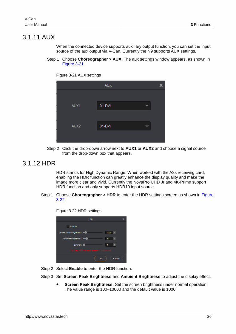
Step 1 Choose Choreographer > AUX. The aux settings window appears, as shown in Figure 3-21.
Figure 3-21 AUX settings
Step 2 Click the drop-down arrow next to AUX1 or AUX2 and choose a signal source from the drop-down box that appears.
3.1.12 HDR
HDR stands for High Dynamic Range. When worked with the A8s receiving card, enabling the HDR function can greatly enhance the display quality and make the image more clear and vivid. Currently the NovaPro UHD Jr and 4K-Prime support HDR function and only supports HDR10 input source.
Step 1 Choose Choreographer > HDR to enter the HDR settings screen as shown in Figure 3-22.
Figure 3-22 HDR settings
Step 2 Select Enable to enter the HDR function.
Step 3 Set Screen Peak Brightness and Ambient Brightness to adjust the display effect.
Screen Peak Brightness: Set the screen brightness under normal operation. The value range is 100–10000 and the default value is 1000.
V-Can
User Manual 3 Functions
http://www.novastar.tech 27
Ambient Brightness: Set the brightness of the surrounding environment where the screen locates. This brightness value can be obtained by measuring. The value range is 0–200 and the default value is 30.
Low Grayscale Mode: Set the grayscale value of the image displayed on the screen. The value range is 0–50 and the default value is 15.
3.1.13 Setting Presets
Saving Presets
When the connected device is the N6, J6, VS7 V1.x.x, VS2 or VS3, the preset will be saved automatically.
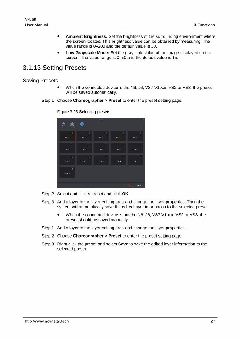
Step 1 Choose Choreographer > Preset to enter the preset setting page.
Figure 3-23 Selecting presets
Step 2 Select and click a preset and click OK.
Step 3 Add a layer in the layer editing area and change the layer properties. Then the system will automatically save the edited layer information to the selected preset.
When the connected device is not the N6, J6, VS7 V1.x.x, VS2 or VS3, the preset should be saved manually.
Step 1 Add a layer in the layer editing area and change the layer properties.
Step 2 Choose Choreographer > Preset to enter the preset setting page.
Step 3 Right click the preset and select Save to save the edited layer information to the selected preset.
V-Can
User Manual 3 Functions
http://www.novastar.tech 28
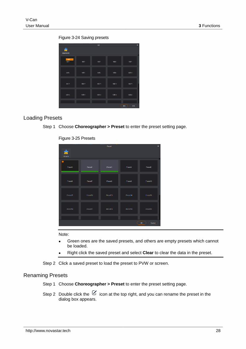
Figure 3-24 Saving presets
Loading Presets
Step 1 Choose Choreographer > Preset to enter the preset setting page.
Figure 3-25 Presets
Note:
Green ones are the saved presets, and others are empty presets which cannot be loaded.
Right click the saved preset and select Clear to clear the data in the preset.
Step 2 Click a saved preset to load the preset to PVW or screen.
Renaming Presets
Step 1 Choose Choreographer > Preset to enter the preset setting page.
Step 2 Double click the icon at the top right, and you can rename the preset in the dialog box appears.
V-Can
User Manual 3 Functions
http://www.novastar.tech 29
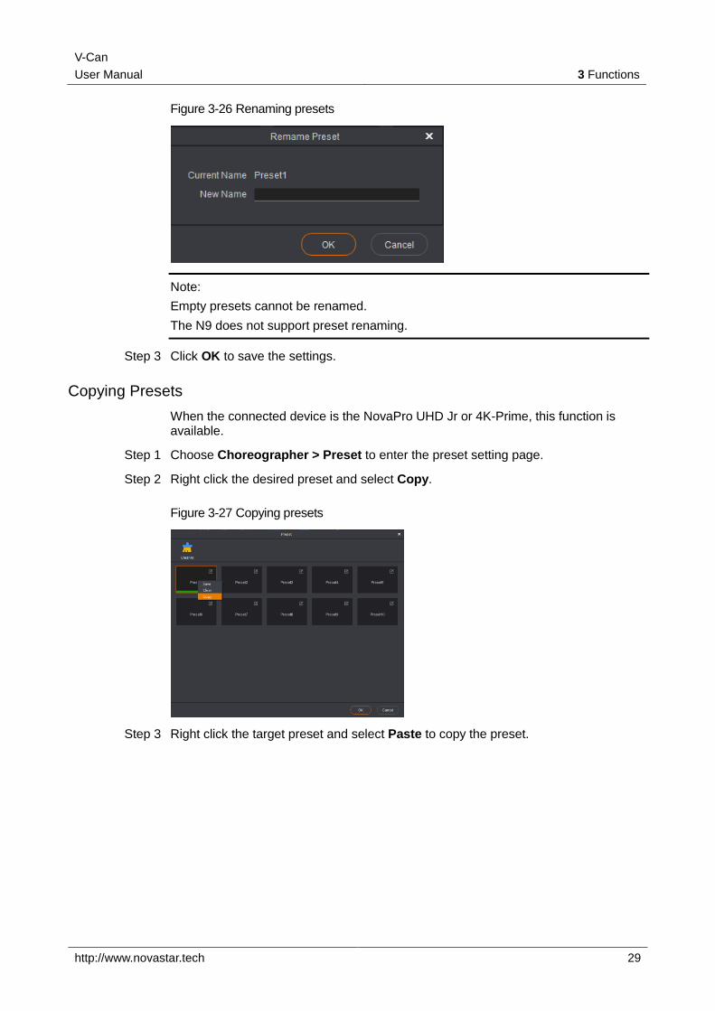
Figure 3-26 Renaming presets
Note:
Empty presets cannot be renamed.
The N9 does not support preset renaming.
Step 3 Click OK to save the settings.
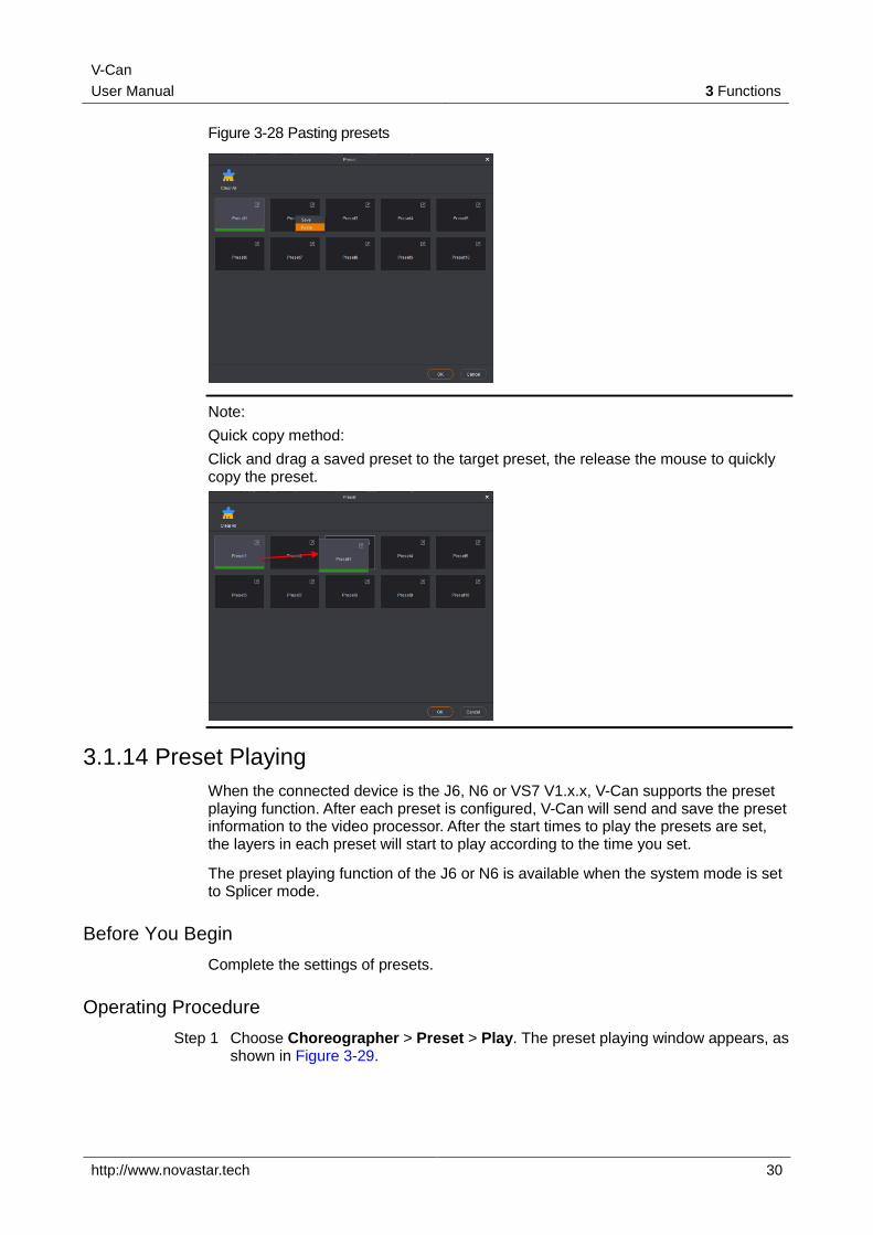
Copying Presets
When the connected device is the NovaPro UHD Jr or 4K-Prime, this function is available.
Step 1 Choose Choreographer > Preset to enter the preset setting page.
Step 2 Right click the desired preset and select Copy.
Figure 3-27 Copying presets
Step 3 Right click the target preset and select Paste to copy the preset.
V-Can
User Manual 3 Functions
http://www.novastar.tech 30
Figure 3-28 Pasting presets
Note:
Quick copy method:
Click and drag a saved preset to the target preset, the release the mouse to quickly copy the preset.
3.1.14 Preset Playing
When the connected device is the J6, N6 or VS7 V1.x.x, V-Can supports the preset playing function. After each preset is configured, V-Can will send and save the preset information to the video processor. After the start times to play the presets are set, the layers in each preset will start to play according to the time you set.
The preset playing function of the J6 or N6 is available when the system mode is set to Splicer mode.
Before You Begin
Complete the settings of presets.
Operating Procedure
Step 1 Choose Choreographer > Preset > Play. The preset playing window appears, as shown in Figure 3-29.
V-Can
User Manual 3 Functions
http://www.novastar.tech 31
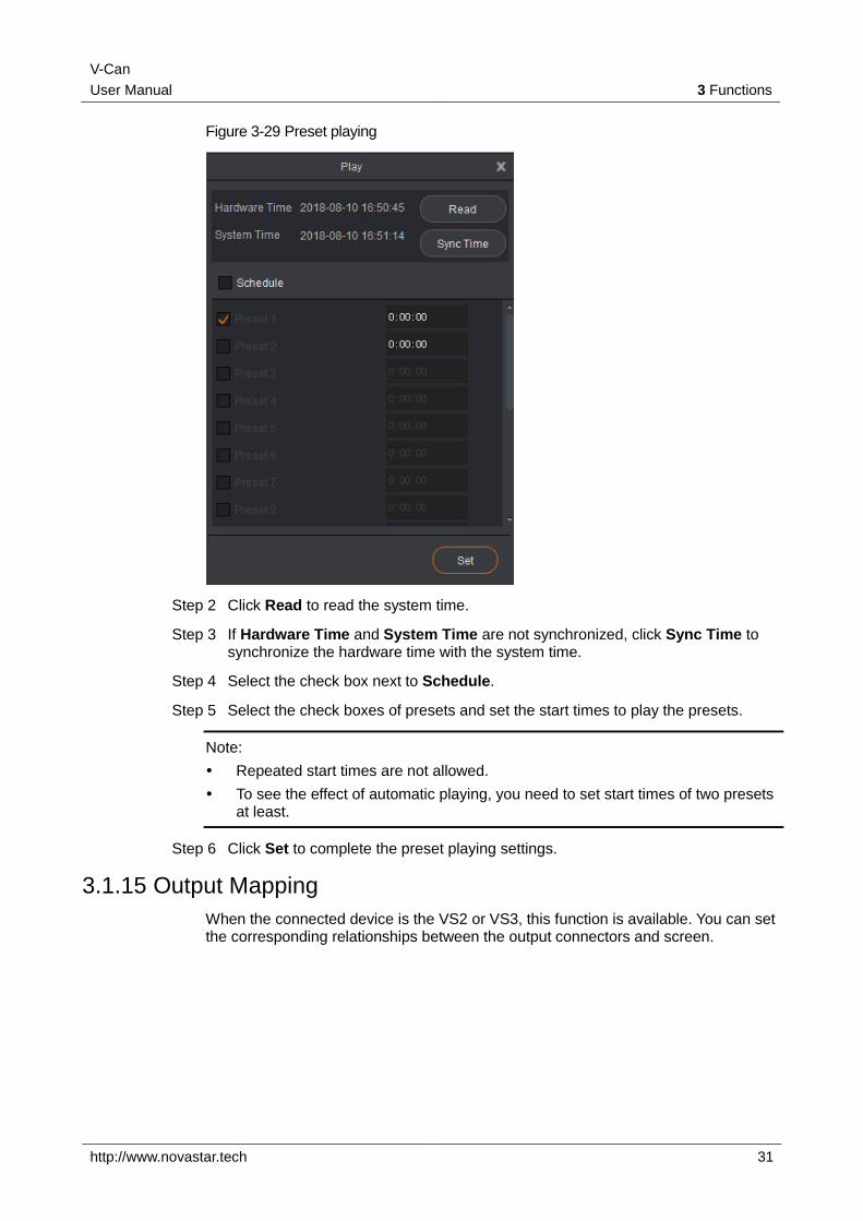
Figure 3-29 Preset playing
Step 2 Click Read to read the system time.
Step 3 If Hardware Time and System Time are not synchronized, click Sync Time to synchronize the hardware time with the system time.
Step 4 Select the check box next to Schedule.
Step 5 Select the check boxes of presets and set the start times to play the presets.
Note:
Repeated start times are not allowed.
To see the effect of automatic playing, you need to set start times of two presets at least.
Step 6 Click Set to complete the preset playing settings.
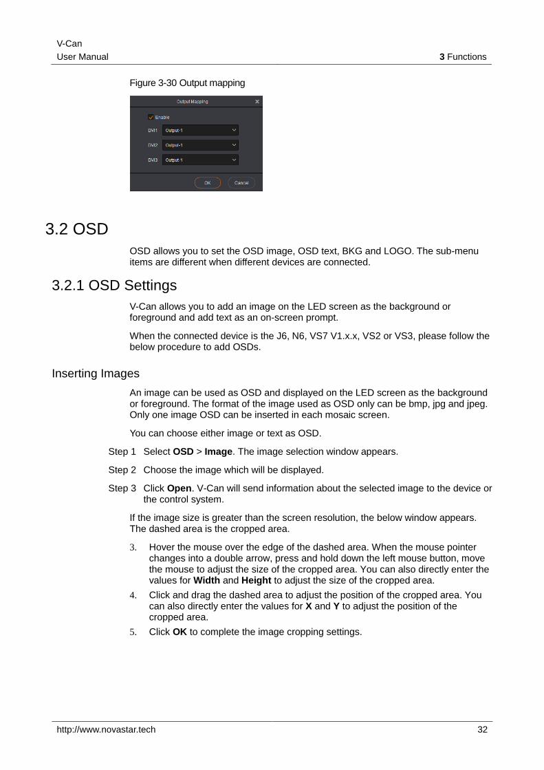
3.1.15 Output Mapping
When the connected device is the VS2 or VS3, this function is available. You can set the corresponding relationships between the output connectors and screen.
V-Can
User Manual 3 Functions
http://www.novastar.tech 32
Figure 3-30 Output mapping
3.2 OSD
OSD allows you to set the OSD image, OSD text, BKG and LOGO. The sub-menu items are different when different devices are connected.
3.2.1 OSD Settings
V-Can allows you to add an image on the LED screen as the background or foreground and add text as an on-screen prompt.
When the connected device is the J6, N6, VS7 V1.x.x, VS2 or VS3, please follow the below procedure to add OSDs.
Inserting Images
An image can be used as OSD and displayed on the LED screen as the background or foreground. The format of the image used as OSD only can be bmp, jpg and jpeg. Only one image OSD can be inserted in each mosaic screen.
You can choose either image or text as OSD.
Step 1 Select OSD > Image. The image selection window appears.
Step 2 Choose the image which will be displayed.
Step 3 Click Open. V-Can will send information about the selected image to the device or the control system.
If the image size is greater than the screen resolution, the below window appears. The dashed area is the cropped area.
3. Hover the mouse over the edge of the dashed area. When the mouse pointer changes into a double arrow, press and hold down the left mouse button, move the mouse to adjust the size of the cropped area. You can also directly enter the values for Width and Height to adjust the size of the cropped area.
4. Click and drag the dashed area to adjust the position of the cropped area. You can also directly enter the values for X and Y to adjust the position of the cropped area.
5. Click OK to complete the image cropping settings.
V-Can
User Manual 3 Functions
http://www.novastar.tech 33
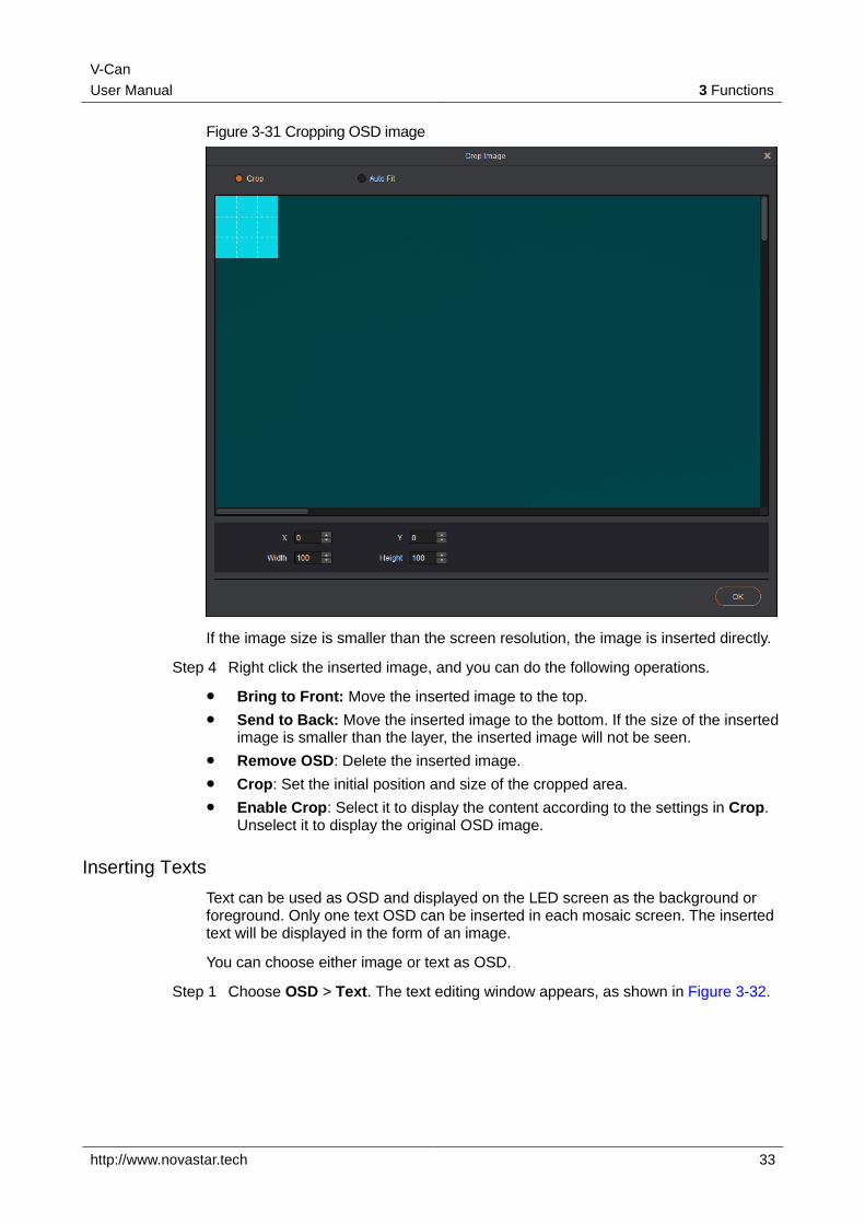
Figure 3-31 Cropping OSD image
If the image size is smaller than the screen resolution, the image is inserted directly.
Step 4 Right click the inserted image, and you can do the following operations.
Bring to Front: Move the inserted image to the top.
Send to Back: Move the inserted image to the bottom. If the size of the inserted image is smaller than the layer, the inserted image will not be seen.
Remove OSD: Delete the inserted image.
Crop: Set the initial position and size of the cropped area.
Enable Crop: Select it to display the content according to the settings in Crop. Unselect it to display the original OSD image.
Inserting Texts
Text can be used as OSD and displayed on the LED screen as the background or foreground. Only one text OSD can be inserted in each mosaic screen. The inserted text will be displayed in the form of an image.
You can choose either image or text as OSD.
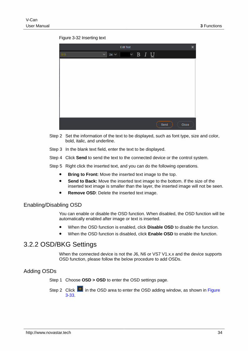
Step 1 Choose OSD > Text. The text editing window appears, as shown in Figure 3-32.
V-Can
User Manual 3 Functions
http://www.novastar.tech 34
Figure 3-32 Inserting text
Step 2 Set the information of the text to be displayed, such as font type, size and color, bold, italic, and underline.
Step 3 In the blank text field, enter the text to be displayed.
Step 4 Click Send to send the text to the connected device or the control system.
Step 5 Right click the inserted text, and you can do the following operations.
Bring to Front: Move the inserted text image to the top.
Send to Back: Move the inserted text image to the bottom. If the size of the inserted text image is smaller than the layer, the inserted image will not be seen.
Remove OSD: Delete the inserted text image.
Enabling/Disabling OSD
You can enable or disable the OSD function. When disabled, the OSD function will be automatically enabled after image or text is inserted.
When the OSD function is enabled, click Disable OSD to disable the function.
When the OSD function is disabled, click Enable OSD to enable the function.
3.2.2 OSD/BKG Settings
When the connected device is not the J6, N6 or VS7 V1.x.x and the device supports OSD function, please follow the below procedure to add OSDs.
Adding OSDs
Step 1 Choose OSD > OSD to enter the OSD settings page.
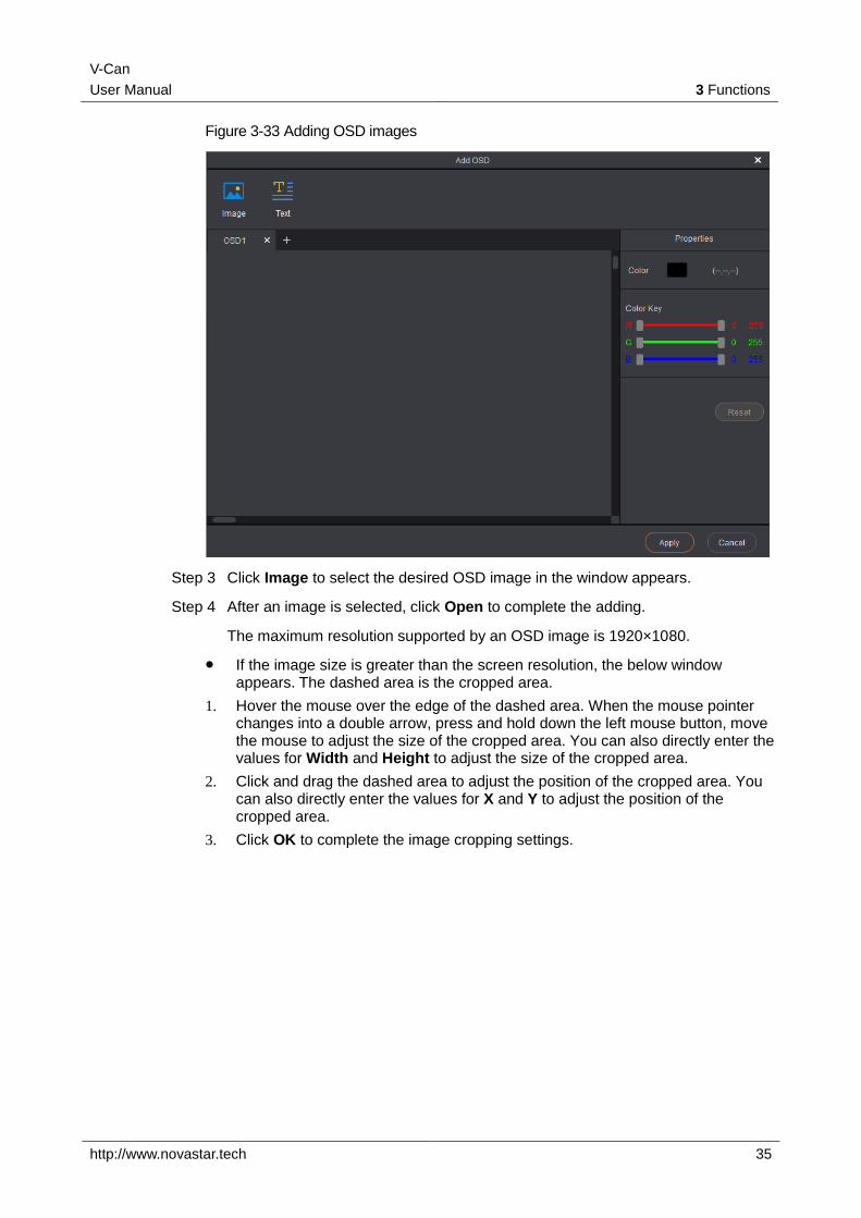
Step 2 Click in the OSD area to enter the OSD adding window, as shown in Figure 3-33.
V-Can
User Manual 3 Functions
http://www.novastar.tech 35
Figure 3-33 Adding OSD images
Step 3 Click Image to select the desired OSD image in the window appears.
Step 4 After an image is selected, click Open to complete the adding.
The maximum resolution supported by an OSD image is 1920×1080.
If the image size is greater than the screen resolution, the below window appears. The dashed area is the cropped area.
1. Hover the mouse over the edge of the dashed area. When the mouse pointer changes into a double arrow, press and hold down the left mouse button, move the mouse to adjust the size of the cropped area. You can also directly enter the values for Width and Height to adjust the size of the cropped area.
2. Click and drag the dashed area to adjust the position of the cropped area. You can also directly enter the values for X and Y to adjust the position of the cropped area.
3. Click OK to complete the image cropping settings.

V-Can
User Manual 3 Functions
http://www.novastar.tech 36
Figure 3-34 Cropping OSD images
Note:
You can select Auto Fit to fit the image to the whole screen.
If the image size is smaller than the screen resolution, the image is added directly.
After the image is added successfully, it is as shown in Figure 3-35.
V-Can
User Manual 3 Functions
http://www.novastar.tech 37
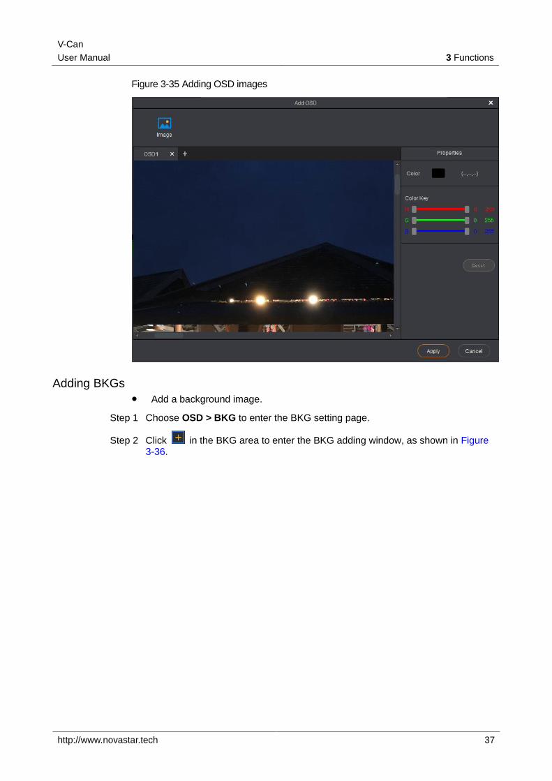
Figure 3-35 Adding OSD images
Adding BKGs
Add a background image.
Step 1 Choose OSD > BKG to enter the BKG setting page.
Step 2 Click in the BKG area to enter the BKG adding window, as shown in Figure 3-36.
V-Can
User Manual 3 Functions
http://www.novastar.tech 38
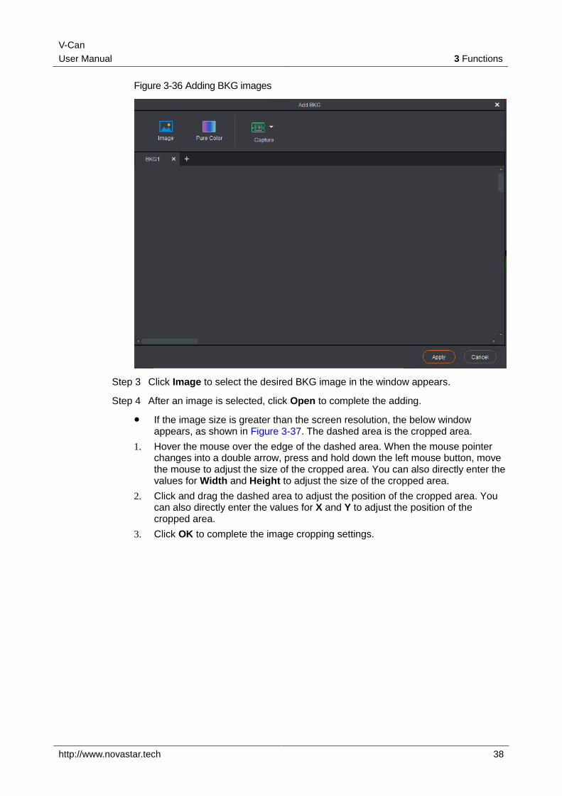
Figure 3-36 Adding BKG images
Step 3 Click Image to select the desired BKG image in the window appears.
Step 4 After an image is selected, click Open to complete the adding.
If the image size is greater than the screen resolution, the below window appears, as shown in Figure 3-37. The dashed area is the cropped area.
1. Hover the mouse over the edge of the dashed area. When the mouse pointer changes into a double arrow, press and hold down the left mouse button, move the mouse to adjust the size of the cropped area. You can also directly enter the values for Width and Height to adjust the size of the cropped area.
2. Click and drag the dashed area to adjust the position of the cropped area. You can also directly enter the values for X and Y to adjust the position of the cropped area.
3. Click OK to complete the image cropping settings.
V-Can
User Manual 3 Functions
http://www.novastar.tech 39
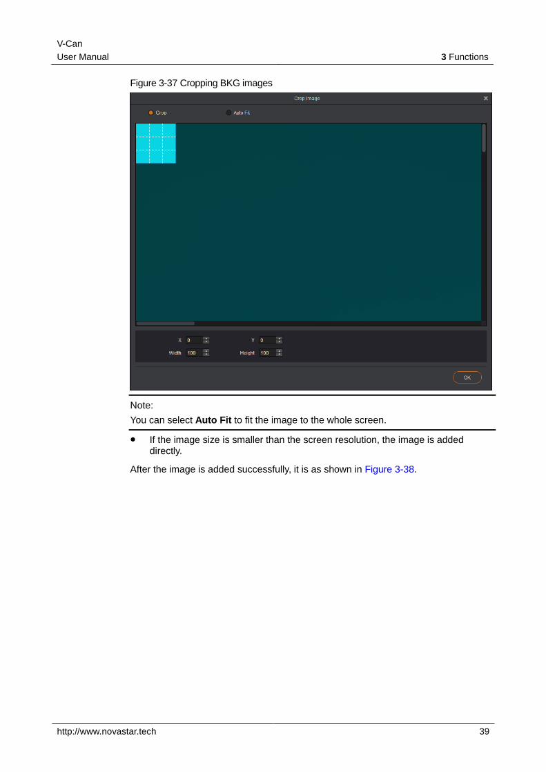
Figure 3-37 Cropping BKG images
Note:
You can select Auto Fit to fit the image to the whole screen.
If the image size is smaller than the screen resolution, the image is added directly.
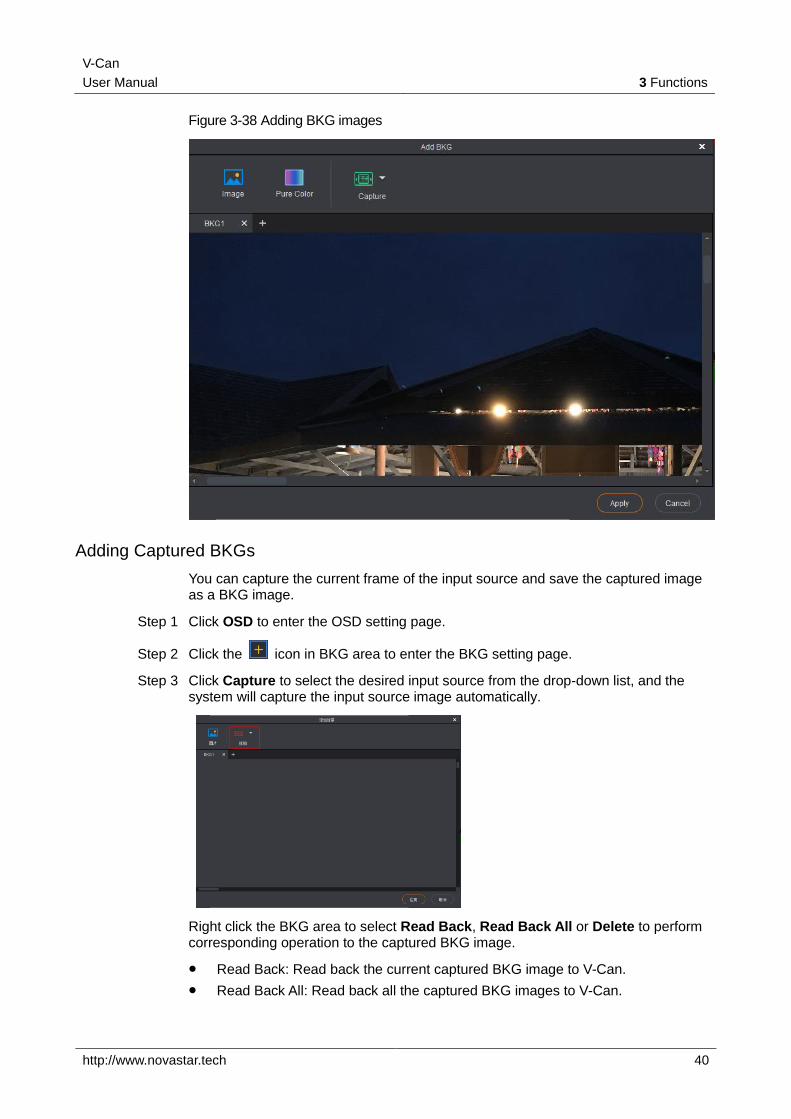
After the image is added successfully, it is as shown in Figure 3-38.
V-Can
User Manual 3 Functions
http://www.novastar.tech 40
Figure 3-38 Adding BKG images
Adding Captured BKGs
You can capture the current frame of the input source and save the captured image as a BKG image.
Step 1 Click OSD to enter the OSD setting page.
Step 2 Click the icon in BKG area to enter the BKG setting page.
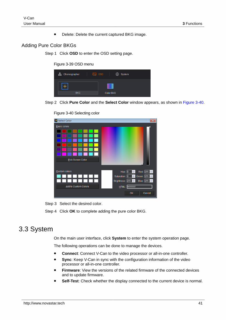
Step 3 Click Capture to select the desired input source from the drop-down list, and the system will capture the input source image automatically.
Right click the BKG area to select Read Back, Read Back All or Delete to perform corresponding operation to the captured BKG image.
Read Back: Read back the current captured BKG image to V-Can.
Read Back All: Read back all the captured BKG images to V-Can.
V-Can
User Manual 3 Functions
http://www.novastar.tech 41
Delete: Delete the current captured BKG image.
Adding Pure Color BKGs
Step 1 Click OSD to enter the OSD setting page.
Figure 3-39 OSD menu
Step 2 Click Pure Color and the Select Color window appears, as shown in Figure 3-40.
Figure 3-40 Selecting color
Step 3 Select the desired color.
Step 4 Click OK to complete adding the pure color BKG.
3.3 System
On the main user interface, click System to enter the system operation page.
The following operations can be done to manage the devices.
Connect: Connect V-Can to the video processor or all-in-one controller.
Sync: Keep V-Can in sync with the configuration information of the video processor or all-in-one controller.
Firmware: View the versions of the related firmware of the connected devices and to update firmware.
Self-Test: Check whether the display connected to the current device is normal.
V-Can
User Manual 3 Functions
http://www.novastar.tech 42
Reset: Reset the configuration information of the connected device to factory settings.
Network: Set the IP address and subnet mask of the controlled device.
Language: Choose the UI language for V-Can.
3.3.1 Connecting Device
Before You Begin
Connect the video processor or all-in-one controller to PC with Ethernet cable or USB cable.
Operating Procedure
Step 1 Choose System > Connect. The system will search for and connect the devices automatically.
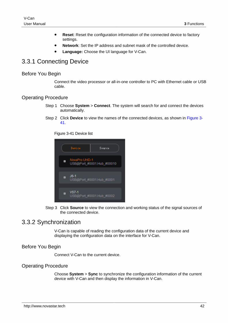
Step 2 Click Device to view the names of the connected devices, as shown in Figure 3-41.
Figure 3-41 Device list
Step 3 Click Source to view the connection and working status of the signal sources of the connected device.
3.3.2 Synchronization
V-Can is capable of reading the configuration data of the current device and displaying the configuration data on the interface for V-Can.
Before You Begin
Connect V-Can to the current device.
Operating Procedure
Choose System > Sync to synchronize the configuration information of the current device with V-Can and then display the information in V-Can.
V-Can
User Manual 3 Functions
http://www.novastar.tech 43
3.3.3 Firmware Update
This function allows you to view the versions of the related firmware of the connected devices and to update firmware.
Before You Begin
Connect V-Can to the current device.
Get the software version supported by the current device.
Operating Procedure
View firmware version information.
Choose System > Firmware. You can view the MCU version, FPGA version and gallery version in the dialog box that appears.
Update firmware.
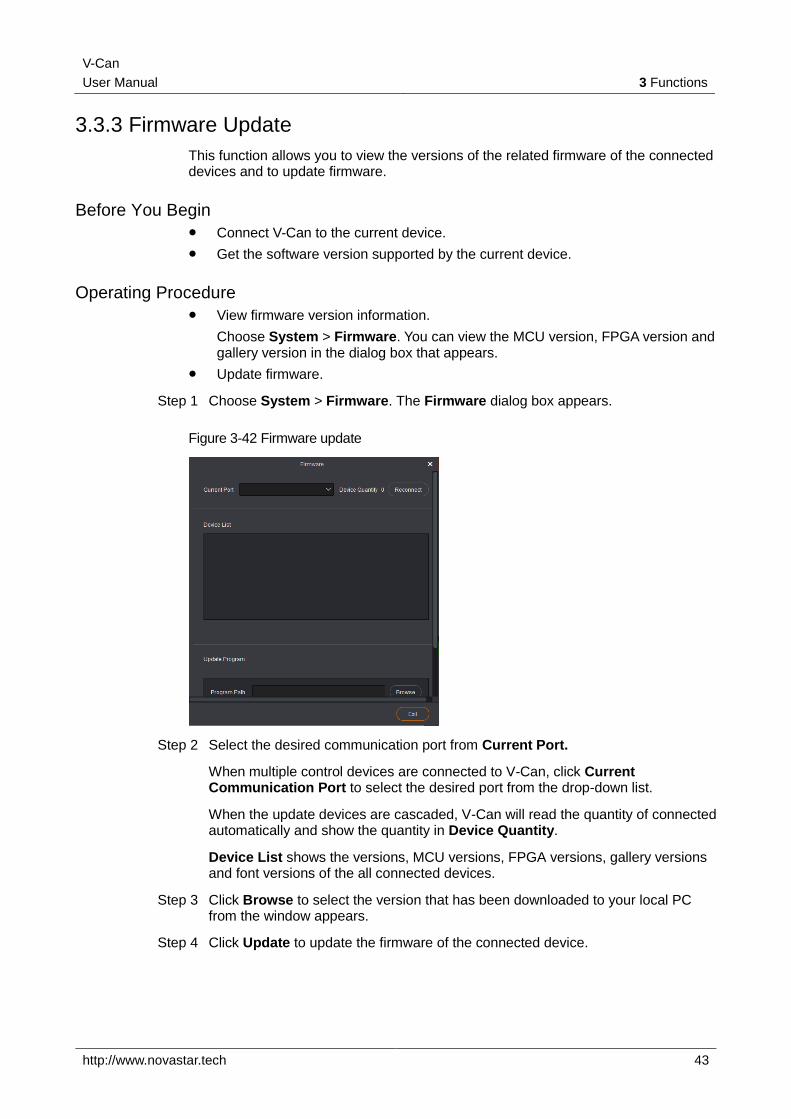
Step 1 Choose System > Firmware. The Firmware dialog box appears.
Figure 3-42 Firmware update
Step 2 Select the desired communication port from Current Port.
When multiple control devices are connected to V-Can, click Current Communication Port to select the desired port from the drop-down list.
When the update devices are cascaded, V-Can will read the quantity of connected automatically and show the quantity in Device Quantity.
Device List shows the versions, MCU versions, FPGA versions, gallery versions and font versions of the all connected devices.
Step 3 Click Browse to select the version that has been downloaded to your local PC from the window appears.
Step 4 Click Update to update the firmware of the connected device.
V-Can
User Manual 3 Functions
http://www.novastar.tech 44
Note:
Click Advanced and type admin to enter the advanced mode where you can update the device MCU, FPGA_A, FPGA_B, gallery and font.
3.3.4 Self-Test
Use the built-in test patterns to check whether the display of the video wall connected to the current device is normal.
Before You Begin
Connect V-Can to the current device.
Connect the current device to a video display device.
Operating Procedure
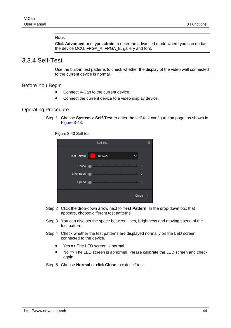
Step 1 Choose System > Self-Test to enter the self-test configuration page, as shown in Figure 3-43.
Figure 3-43 Self-test
Step 2 Click the drop-down arrow next to Test Pattern. In the drop-down box that appears, choose different test patterns.
Step 3 You can also set the space between lines, brightness and moving speed of the test pattern.
Step 4 Check whether the test patterns are displayed normally on the LED screen connected to the device.
Yes => The LED screen is normal.
No => The LED screen is abnormal. Please calibrate the LED screen and check again.
Step 5 Choose Normal or click Close to exit self-test.
V-Can
User Manual 3 Functions
http://www.novastar.tech 45
3.3.5 Factory Reset
If you want to clear device configuration information or user preset information, this function allows you to clear the configuration information of current device with one click.
Before You Begin
Connect V-Can to the current device.
Operating Procedure
Step 1 Choose System > Reset.
Step 2 Please carefully read the prompt message that appears. Clicking Yes will clear all the configuration information of the current device.
3.3.6 Network Settings
V-Can can be connected to hardware device through RJ45 Ethernet cable. The IP address and subnet mask can be set in V-Can.
Operating Procedure
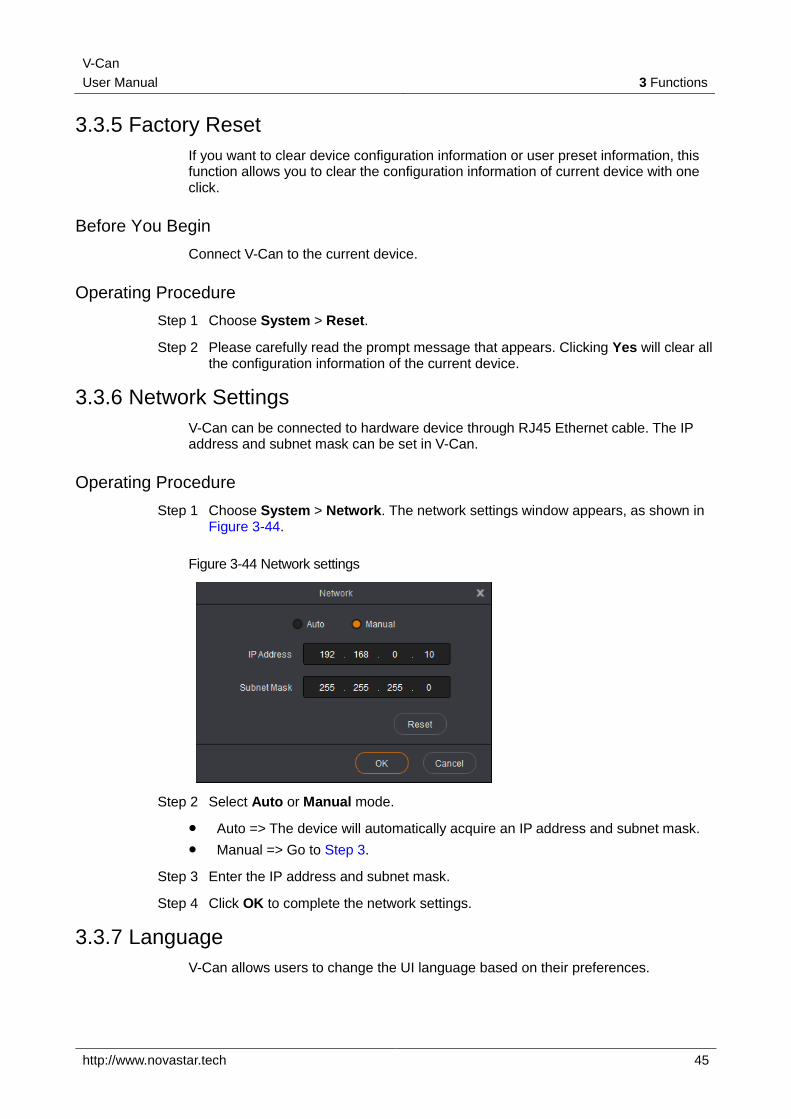
Step 1 Choose System > Network. The network settings window appears, as shown in Figure 3-44.
Figure 3-44 Network settings
Step 2 Select Auto or Manual mode.
Auto => The device will automatically acquire an IP address and subnet mask.
Manual => Go to Step 3.
Step 3 Enter the IP address and subnet mask.
Step 4 Click OK to complete the network settings.
3.3.7 Language
V-Can allows users to change the UI language based on their preferences.
V-Can
User Manual 3 Functions
http://www.novastar.tech 46
Operating Procedure
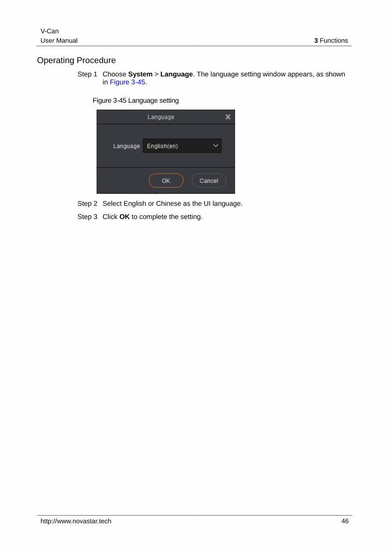
Step 1 Choose System > Language. The language setting window appears, as shown in Figure 3-45.
Figure 3-45 Language setting
Step 2 Select English or Chinese as the UI language.
Step 3 Click OK to complete the setting.