using collaboration platforms for the development of … · using collaboration platforms for the...
TRANSCRIPT
1
Using Collaboration Platforms for the Development of Civil Engineering Projects
ABSTRACT: Recently, new technologies and tools on software and Internet have emerged, in the
area of information systems integrated with building design, that focus the Civil Engineering project
management applied throughout its complete lifecycle. Contractor entities have currently the challenge
to implement and adapt themselves to these new technologies, preparing for a future reality in the
medium to long term.
This dissertation seeks to analyze some of the existing tools as regards of Building Information
Modeling and Collaborative Platforms, applying them to the current reality of the contract formation,
within the context of a procedure in order to perform a public contract. In this sense, it was analyzed
the potential of the existing software applications of Revit, Archicad and VICO Software families,
carrying out activities currently performed by the Contractor, related to quantities take-off, detection of
errors and omissions, scheduling, budgeting, construction preparation and supply chain management
and outsourcing. It was also tested the Asite portal in relation to its interoperability with applications for
eCollaboration.
To test the technologies it was used a construction project called "Centro de Saúde Tipo",
corresponding to a fictitious health care center.
KEYWORDS: Building Information Modeling; eCollaboration Portal; Building Project Management;
Contractor; Interoperability; Public Procurement.
1. INTRODUCTION
This dissertation seeks to identify opportunities to develop collaborative platforms functionalities for
managing Civil Engineering projects, at the stage of the construction contract formation. The approach
was mainly focused on the Contractors optical, in dealings with other entities involved in contract
model Design-Bid-Construction.
It was also examined the potential of Building Information Modeling (BIM) tools, when used by the
Contractor, for tendering to a public construction health center, named “Centro de Saúde Tipo”. This
intervener starts its shares in the tender phase. The preparation of its bid starts from the design
documents that are provided by the public Owner, received from the procurement portals in digital
formats.
The major issues that were addressed in the use of these BIM tools and which were the subject of
analysis in this dissertation are as follows: quantity take-off; errors and omissions; scheduling;
budgeting; work preparation; and supply chain and outsourcing management. At the end, it was also
analyzed the potentiality of Asite collaboration platform (eCollaboration) for interaction with the BIM
tools evaluated.

2
2. CONSTRUCTION PROJECT DEVELOPMENT
In examining, on the Design-Bid-Construction contract method is taken into account the systemic
vision of the integrated lifecycle for the development of construction projects, consisting in three main
phases: design, evaluation and document creation; bid and tendering; and facility management. The
decomposition in the respective sub phases was made taking into account the legal rules witch
approves the compulsory content of program and project execution.
Figure 1 - Construction project lifecycle (adap. from Costa, 2010)
The interveners involved in the development of a
Civil Engineering projects depend essentially on
the type of Owner, the type of construction and
the contract model that is set. In the Design-Bid-
Construction contract method, the major players
usually are: the Owner, the Designers team, the
Security and Health Coordination team,
Surveillance team, the General Contractor, the
Subcontractors and Users of the buildings. In this
contract method the Owner is usually the
responsible for the communication between
parties, possessing, apart from the contractual
relationship with Designers, Supervision team
and General Contractor, a direct channel for the
information exchange.
3. CIVIL ENGINEERING AND COLLABORATION PLATFORMS
In Portugal, since 1999 several Internet portals in the Civil Engineering were created, namely
Econstroi.com (companies directory and e-procurement), Construlink (eCatalogue and company
directory) and the “Portal da Construção” (eCatalogue and company directory). Also the construction
of industrial associations, associations of manufacturers of construction products and professional
associations, have portals for the dissemination of information related to the sector.
The collaboration platforms are an emerging category of electronic Internet platforms that provide an
infrastructure that facilitates communication and collaboration between all project partners
(eCollaboration), on a desktop, in view of achieving common goals. The main services of collaboration
platforms are the e-mail (e-mail, calendaring, contacts), team collaboration (sharing files, ideas, notes,
task management, wiki and text search), collaboration and real-time communication (presence, IM,
Web conferencing, application sharing and desktop, audio and video conferencing) and social
computing tools (blog, wiki, RSS, tagging, sharing tags) (Wikipedia, 2010). Some Civil Engineering
collaboration portals can be found on Internet: BuildOnline, 4Projetcs, BIW, Aconex and Asite.
With the publication of the legal procurement law (Código dos Contratos Públicos - CCP), in 29th
January of 2008, and the other legal documents that regulate it, emerged a set of specialized portals

3
for supporting public procurement contracts. Generally, these platforms are the support for procedure
management of the tender of public contracts. Through them, the public Owner provides the relevant
documents to each procedure, which may be obtained by the candidates. It also can receive the
tenders, chronological manage the entire process, manage request for information from tenders
(RFIs), manage the errors and omissions identified in the tender phase, manage the official
notifications to the involved entities and manage communications of the results and decisions.
4. BUILDING INFORMATION MODELING (BIM)
According to Charles Eastman (1999), BIM is a digital representation of the building process to
facilitate exchange and interoperability of information in digital format. This digital representation of the
building is composed by a set of objects that are generally three-dimensional shaped (3D) which
aggregates information in the database, called by "smart objects" (Hardin, 2009), integrated into a
single file source. Smart objects represent real components of the buildings, such as doors, windows,
walls or roofs (Smith et al., 2009). Each component has data content associated, that adds useful
information from any stage of the project lifecycle, for the use of any intervener that needs it.
The opportunities of BIM tools exist, even if performing the conversion from 2D formats, with
Contractor in-house resources. The advantages are evident in the design, graphical representation, in
the assessment of alternative solutions, in the site planning, in the compliance verification of regulation,
on the assessment of building solutions, on the quality of information for construction execution, in the
scheduling documentation, in operations sequencing, in operations coordination and on training and
communication with stakeholders (AGC, 2008).
Several BIM softwares can be used. However, there is no individually software on the market that
completely responds to the challenge of creating a compendium on the 3D model. The various
software found have features that complement each other, to apply to each phase of the project
development, and users should choose which is best to suit their needs.
There were analyzed three software families, in particular, Autodesk, Graphisoft and VICO Software
whose features suit Contractor needs, in the stage of contract formation.
4.1. Interoperability
The concept of interoperability is an integral
part of the BIM concept, trying to change the
traditional view of "1 x n" workflow, where each
one of the interlocutors relates to "n" others, to
the workflow's vision of "n x 1", in which each
of the "n" interlocutors incorporates a set of
shared information on a single model.
Figure 2 - BIM – Interoperability view

4
The "nD" phenomenon is translated as corresponding to the full interoperability of all interlocutors in
the project development, creating only a single protocol for delivery formats of digital information to
which all are linked.
In a simplified form, the buildingSMART summarizes BIM interoperability through the following
expression:
in which IFC represents Industry Foundation Classes, IFD represents International Framework for
Dictionaries and IDM represents Information Delivery Manual.
The Industry Foundation Classes (IFC) Protocol was created in 1994, to enhance this interoperability.
It is an object-oriented digital format associated with a data content, which proposes to facilitate
interoperability in the construction industry, in particular, for use of BIM tools. The main generation
software companies, including the three BIM software families who were tested, submitted their
applications to the certification process managed by buildingSMART.
International Framework for Dictionaries (IFD) Protocol aims to be the international reference library
for interoperability in support of the construction industry, enabling the link between any model and
various databases with information design and construction products (IAI, 2010a). This component will
allow manufacturers of construction products to disclose their products with the necessary information
to integrate in a BIM project, allowing any interlocutors to select or compare them in the light of the
objectives to be achieved.
The Information Delivery Manual (IDM) Protocol intends to facilitate the relationship between the
software and the development of the project. It aims to define the creation processes (workflows),
detailing the specifications of how the information should be integrated in the model and identifying the
interveners responsible for such addiction, at any stage of its development phase. The IDM will still
identify the creation of a set of functionalities associated with the model that can be used during its
development or, subsequently, by the building users (IAI, 2010b).
4.2. BIM Software
Both families of software ArchiCAD and Autodesk have interoperability applications based on the logic
of direct connection files. It can also be found for both software applications Internet catalogues of
objects for inclusion in BIM models. Some of the available objects have already aggregated data
supplement and is accompanied by technical product data sheets in external files in DOC or PDF
formats, provided by the construction product manufacturers. However, many other objects are also
developed by users and made freely available, not containing information beyond its geometry. To
manage the objects parameters, the softwares have its add-ons that use MDB or ODBC drivers that
allow for communication with databases.
The VICO Software has developed a set of functionalities related to the Contractor activity, extending
the ArchiCAD 11 framework, in the software application that is called Constructor. A set of four other

5
softwares from 2008 version (Estimator, Control, Cost Manager and 5D Presenter) complement and
work information for the created 3D models. The VICO Software began by defining the Virtual
Construction Process and identifying the workflow steps: Preparation, Modeling, Estimation,
Sequencing, Scheduling, Cost Management and Budget Simulation model, 5D progress Control, 5D
Simulations and Earn Value Management.
Each of the software was developed to meet the needs of the construction development phases, as
well to follow the steps of the virtual construction process, complementing each other. The following
figure represents the complete view Virtual Construction process:
Figure 3 - Virtual construction process (VICO, 2008a)
The concerned softwares are suitable for the
creation of several documents used in the
relationship between the Contractor and the
Owner, namely: tender proposals, cost control,
planning, monitoring and work preparation.
For internal purposes of the Contractor,
several utilities are also identified for these
softwares: re-budgeting, supply chain control,
sequencing control and financial performance
control of the construction development.
5. 3D MODEL DEVELOPMENT
5.1. Model Development Stages
In public procurement, the stages of design process are: preliminary program; base program;
preliminary design; basic design; execution design; and technical assistance. Highlight the fact that
the concept of As-Built design define in the legal rule is integrated into technical assistance phase.
For the BIM implementation there are two classifications defined by the American Institute of
Architects (AIA) and by Autodesk (2010), respectively. The American Institute of Architects (AIA) has
developed the AIA E202-2008 Protocol laying down five levels of detail (LOD) for the BIM model
development: 100. Design; 200. Approximate Geometry; 300. Precise geometry; 400. Manufacturing;
500. As-Built (EIA CC, 2008). Autodesk also defines five levels of detail for the BIM model
development (Autodesk, 2010): L1, L2, L3, CD (Construction Documents), As-built model. The
descriptions show similarity between the levels of detail defined by AIA and by Autodesk. The Table 1
shows the comparison between legal rule classification and the BIM classification.
In this comparison, it was found that the legal rule classification is not directly level-to-level
corresponding to AIA or Autodesk classification. There is some overlap in the case of the LOD 400 or
CD level. However, it was realized that the methodology in BIM classification is not rigid, and it is
adaptable to the legal rule classification. It is the responsibility of the project manager to define the
limits, responsibilities and contributions of each actor in the process.

6
L1 L2 L3 CD As-Built
Project Stages LOD 100 LOD 200 LOD 300 LOD 400 LOD 500
Preliminary Program Base Program Preliminary Design Basic Design Execution Design Technical Assistance
Table 1. - Comparison between legal rule classification and BIM classification
5.2. Model Presentation
The model used for the development of this study corresponds to a fictitious health center building,
called "Centro de Saúde Tipo”, whose location, also fictitious, is situated in the municipality of Barreiro.
Figure 4 - Revit Arch. 2010 – Model general view
The model was developed in each one of the softwares, previously referred, with the appropriate level
of detail necessary for the tests that were in consideration. The components integrated in the model
had a level of detail between the LOD 200 and the LOD 400. In this model it was not introduced the
MEP components.
5.3. Modeling Development Starting from Bid Process
The first aspect to be defined in relation to the model development corresponds to the level of detail
that will be implemented at this stage. This will have an impact in the selection of smart objects that
will be integrated in the model. In this phase of the project, the fact that the characteristics of building
materials are already defined in the design documents easily allows the definition and selection of
materials and digital equipment to integrate in the model. However, requires a major effort, since the
initial study and analysis of the specifications, identification of objects, search of existing digital objects
(in the online catalogue) and the creation of nonexistent digital objects.
Currently, the provision of relevant digital design documents is generally done in 2D format. It was
identified better suitability for modeling creation from vector formats (DWG, DXF, DGN, etc.). The main
aspects identified that influences the modeling work were:

7
1. The model level of detail defined; the definition of responsibility and interlocutors in the
modeling process; 2D elements conversion; number of models and criteria for their
submission, namely, origin point (0,0,0), scales, colors, blocks and views; rules, file format and
file sharing model (Eastman et al., 2008 and AGC, 2008).
2. The criteria for the object definition and the model can also be influenced by the solutions
described in details of design documents, specifications and other written documents.
3. The creation of de 3D model from 2D format files goes beyond the scope of geometric
information contained in each drawn, so it is essential to ensure compatibility between the
model and all relevant draws available, in particular, with layouts, levels, sections or details.
4. The modeling work can also be influenced by issues relating to the objectives for which the
model will be used, including quantity take-off, budgeting, scheduling, interoperability with third
parties, detection of errors and omissions and the modeler should have a good perception of
the other software functionalities.
5. As a principle, modeling should seek maximum approximation to reality of construction site
tasks, in particular, regarding layouts, levels, sections and details, distance between elements,
dimensions, tolerances, space, modularization, repetition, similarity, uniformity and use of
standardized sizes (Nepal et al., 2008).
6. An understanding of modeling methodologies should follow a continuous improvement cycle,
creating, if possible, good practice guides for the use of objects (Plume et al., 2006) and
accompanying with periodic conformity checks between 2D documents and the 3D model,
regarding the quality and level of detail of information.
6. ERRORS AND OMISSIONS
6.1. Errors and Omissions Legal Aspects
Under the CCP it is defined the kind of situations which may constitute errors and omissions, namely:
aspects or data that may prove unconformity with reality; kind or amount of benefits which are strictly
necessary for full implementation of the subject of the contract to be awarded; technical implementing
conditions of the subject of the contract to be concluded that the Contractor does not consider feasible.
In order to enhance the identification of errors and omissions through BIM model, this must have as
fully as possible the following characteristics:
1. The level of details of objects according to the specifications defined in design;
2. Modeling the necessary design elements defined;
3. Level of detail of the model between the LOD 300 and the LOD 400;
4. Definition of construction processes to be implemented;
5. Definition of the site plan;
8
6. Quantity take-off according to the criteria defined in the design documents;
7. Definition and results from automatic verification processes of models conformity.
BIM tools bring an important set of benefits below: 3D visualization and automatic verification
processes; automatic quantity take-off of the model components; simulation activities and
implementation phases of the project; confrontation with the local conditions.
6.2. 3D Visualization and Automatic Verification Process
The reality of the Universe is three-dimensional. Thus, the 2D representation of Civil Engineering
projects usually used assumes the capability of abstraction that humans possess. Creating and
visualizing a 3D model, through the tools BIM, including checking the traditional 2D formats, facilitates
the detecting of errors and omissions in the interactions between the various elements of the project.
Despite the enhancement of tools, the perception of the error depends always on the intervention of
the modeler, on the criteria and on the procedures that can be created for the visual analysis. The
main innovation was the emergence of automatic tools that enable to identify spatial 3D clash
detection or property clash between objects. However, it is the modeler responsibility to validate if the
situations identified by the softwares correspond to real error and omissions situations. In this context,
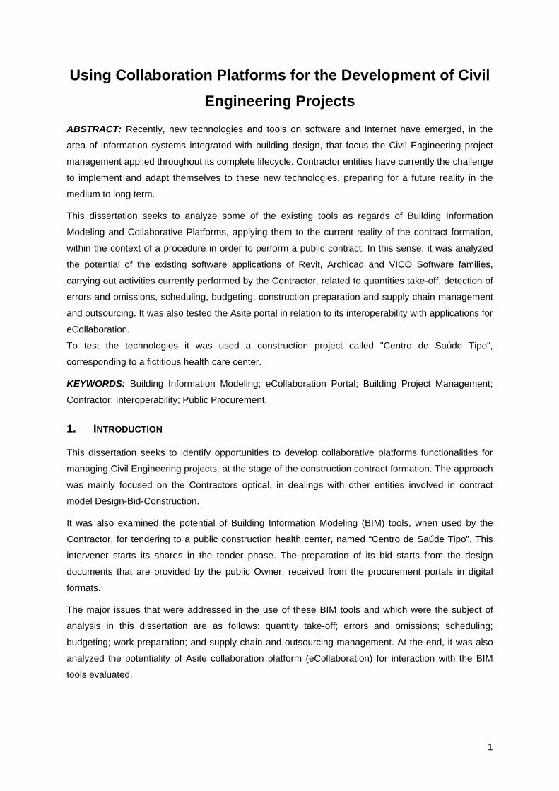
the developed model in Revit Architecture was analyzed in Navisworks Manage 2010.
Figure 5 - Navisworks – General model view
This software allows the verification of three
spatial clash detection options: hard clash,
clearance clash and duplicates. Using the
software features of Search Set and Selection
Set will allow the verification of interference
related to the characteristics and properties of
the objects.
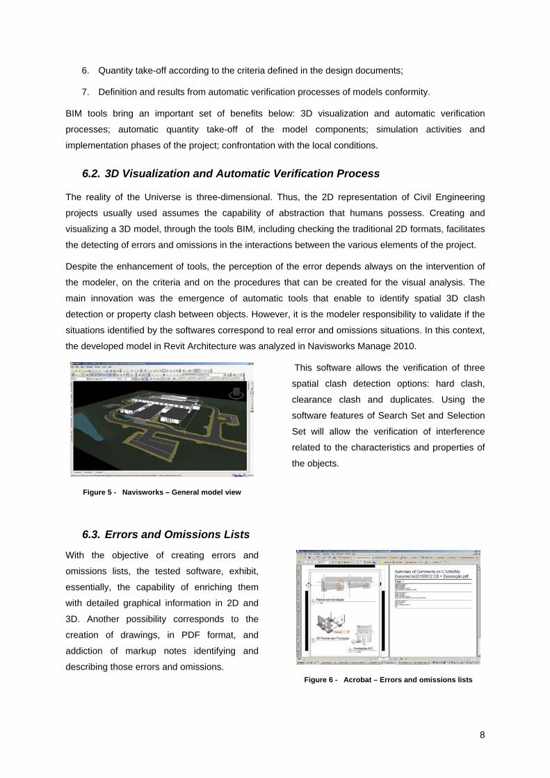
6.3. Errors and Omissions Lists
With the objective of creating errors and
omissions lists, the tested software, exhibit,
essentially, the capability of enriching them
with detailed graphical information in 2D and
3D. Another possibility corresponds to the
creation of drawings, in PDF format, and
addiction of markup notes identifying and
describing those errors and omissions.
Figure 6 - Acrobat – Errors and omissions lists

9
6.4. Site Conditions Checking
The site conditions checking was tested by importing the model form from Revit to Google Earth. It
was used the SketchUp (3D freeware image editing software) as an intermediary software to reference
the location of the project in Google Earth. With this analysis, it was possible to simulate the existence
of neighboring buildings, the access site conditions and the interference with the terrain topography.
Figure 7 - Google Earth – Site Conditions Checking
The identified methodologies do not replace
the traditional in-place site verification.
However, these methodologies are quite useful
for the prior identification of constraints to
confirm during this visit. Some Google Earth
pictures can have a significant delay.
7. AUTOMATIC QUANTITY TAKE-OFF
The current state of the art regarding the quantity take-off criteria implies a challenge in the
development of software that uses 3D models. In spite of legal rules to establish a set of criteria, there
is still an absence regarding the official standards. These conditions allow the emerging of a significant
heterogeneity of criteria agreed between the various actors or defined by designers. Thus, softwares
must ensure enough versatility for quantity take-off use.
The automatic quantity take-off of the elements of the model was tested through the interaction of two
applications of VICO software – the Constructor and the Estimator. For this action, the VICO software
provides a user manual (VICO, 2008b) where it can be identified, for each type of object, which the
properties are available for the automatic calculation. The following table shows some of those
properties for determining generic quantities and formworks area:
Table 2. - Object properties regarding quantity take-off (VICO, 2008b)
The obtained results were
satisfactory for the objectives
pursued. It allowed to obtain the
quantities for several aspects
related to the construction
methods, for identifying errors
and omissions, for budgeting and
for scheduling.

10
8. BUDGETING
Within the framework of budgeting to obtain the Selling Value and the Unit Prices, it was assumed the
cost structure composed by: direct costs (CD); indirect costs (CI); Not Industrial Cost Not; and
Contribution Margin (CM).
The Estimator allows to develop a very versatile budget method, regarding the assumed budget cost
structure. Despite this fact, it was identified that the logic behind this application is better suited to
determine the cost of the set of objects of the same nature, included all its components.
Thus, through Estimator’s Resources, Methods and Recipes database the direct costs of objects can
be determined. Setting the remaining indirect costs, non-industrial Costs and contribution margin is
performed through the definition of monetary values or percentages on the direct costs.
This software also allows includes the value-
added Tax (VAT). Subsequently, the
application provides various types of reports
and information allowing exporting in XLS file
formats, in particular, price list, compose price
list and unit price list.
Figure 8 - Estimator – Unit Price List
9. SCHEDULING
The development of scheduling was carried out from the synchronization of information between three
softwares: the Constructor, the Estimator and the Control. Those softwares enable the creation of the
Work Breakdown Structure (WBS) associated to the elements of the model, and relate it with each
quantities and the price structure created in Estimator.
Within Control, it can be developed planning
and scheduling, including, the sequencing of
activities and tasks, resources commitment
and revenues, the determination of the task
duration, management of resources loads and
risk management. The figure beside presents
the result of scheduling in a Gantt Chart view.
Figure 9 - Control – Gantt Chart view
10. CONSTRUCTION SITE PLANNING
The developed construction site planning has had the following objectives:
1. To resource estimation committed for budgeting the site plan and for the tendering;

11
2. The creation of documentation for response to the requirements of practical development of
the health and safety plan, upstream of the consignment (e.g. site plan);
3. The creation of work plans for the Contractor teams (e.g. Casting and Formworks plans);
As in the model creation, also the stages of construction development can be modeled in 3D, through
the introduction of construction objects. So, it can also be checked for interference, taking into
consideration sequencing, since the model already has associated schedule information.
The site plan was modeled on VICO Constructor, possessing a very wide range of objects related to
the construction process, like cranes, trucks, truck mixers, concrete pump truck , concrete truck, office
modules, WC modules and fences.
Figure 10 - Constructor – Site plan model view
Figure 11 - Constructor – Model slab formwork
The formwork plan was also modeled on VICO Constructor, using the respective objects, in particular,
extenders, beams, plates, platters, formwork, guard rails or access stairs. After creating the formwork
model it was also modeled the casting conditions and the work site access, through the introduction of
its equipment: concrete pumps truck and concrete trucks.
The Navisworks enhances the sequencing clash detection, through the association of a Timeliner to
the model elements, which can be created directly in the software or be associated with an external
file formats as MPP, Primavera Project Management or CSV. Thus, the construction clash detection
now takes into consideration the constructions tasks and also the provisional site plan equipment.
The 5D Presenter from VICO software is able
to create presentations, adding the scheduling
and costing scale. In this way, 4D and 5D
simulations may be performed, sequencing
checking of the constructing, as well as the
Earn Value Management simulation.
Figure 12 - 5D Presenter – 4D and 5D simulation
The possibility of creating construction virtual presentations constitutes a useful tool for better
perception of all project partners, especially with those without technical training or experience related
to Civil Engineering.

12
Brad Hardin (2009) presents the following advantages in using these tools in the Oakland Bay Bridge:
• Better information between design and construction teams about planned construction
process;
• Helps to communicate to decision makers when certain activities will take place and the
relationship among key milestones;
• Fosters more collaboration among project partners and stakeholders;
• Enables the public to clearly see what the project will look like over the course of construction;
• Facilitates media campaigns that effectively communicate plans closures and traffic detours.
11. BIM SUPPLY CHAIN MANAGEMENT
The current features of the construction execution can be characterized by the predominance of
construction performed in place, causing the existence of temporary supporting site equipments. The
information exchange between the Contractor and Surveillance team is also carried out in site, and the
results of verifications, meetings and inspections recorded in traditional construction book.
Despite the limitations laid down by the design, by the specifications and Surveillance team, the
General Contractor has a wide freedom for the materials and subcontractors selection. The selection
criteria used by the Contractor regarding supplies or subcontractors involve ensuring compliance with
the requirements of the project and the specifications, the timely provision, ensuring legal or agreed
with the client and, above, the cheapest price. This methodology has remained over recent decades
and it hasn’t brought productivity benefits to the construction sector.
The objective of BIM Supply Chain Management corresponds to enhance the application of 3D digital
workflows, integrating with the principles of LEAN production in construction processes, to achieve
added value optimization of processes and reduce the number of activities without added value.
This matter it can be identified three areas that it should be recalled:
• The creation of electronic catalogues as a way to increase the interoperability between
partners in the project development and the manufacturers of construction products;
• The execution control from conception to implementation of components in the construction;
• The streamlining of decision-making procedures concerning human or material resources,
surrounded by multi criteria assessment.
The use of electronic catalogues by the Contractor enhances the resolution of several of its needs,
including:
• easy comparison of information regarding the construction product characteristics with the
specifications respectively defined in the design documents;
• easy identification of alternative solutions to the design that can be translated into benefits for
the General Contractor, for the Owner and for Users;

13
• Easy procurement process regarding supplies and subcontracting;
• Enhance the use of more in-depth and complex tools to support decision-making;
• Greater transparency in the information provided to Monitoring team for the approval of
alternative solutions;
• Enhance communication with all project partners (Owners, Contractors, Designers or Users)
regarding the impact of proposed solutions;
Under the executing control of components to include in the building, it can be distinguished between
two phases where BIM tools have proved to be very facilitating: manufacturing and application.
Concerning manufacturing, BIM tools enhance the use of automated production processes, through
the use of Computer Numerically Controlled (CNC) production (Hardin, 2009).
Regarding the application, BIM tools enhance the components application coordination and the task
management, by creating more detailed implementation plans, sequencing animations and clash
detection. Brad Hardin (2009) presents a set of current technologies, including radio frequency ID tags
(RFID), Laser Scanning (LADAR), GPS Locators, used for identifying the components and the place
where they should be applied, using computers manually transported.
Brad Hardin (2009) relates the virtual building process and BIM methodologies with the Lean
Production, showing the following advantages: offers the possibility to contract construction team or
fabricate components accurately; reduces and limits the number of hours of work in the area of
application; coordination of information more efficient by reducing the paper used, problems of
versions and approvals; more efficient coordination in supply chain, reducing stocks; decrease in the
number of supplies and waste; lower total cost of the engineering and detailing work of the project.
The decision problems within the supply chain management and outsourcing can be characterized like
multi criteria comparison problems. The design and the specifications of any construction project has
implicitly written in itself a set of values, social, economic and political, for which they have been
inputted by the designers. As an organization, the General Contractor also has its own structure of
values implicit in its mission, in keeping with the strategy and objectives of the company, and that
transmits to his team involved in the project, through the objectives which stipulates for them.
Thus, the combinative character which may affect the supply chain and outsourcing, that due to the
extension of the set of alternatives that grows quickly and reaches levels much higher than those
dominated by human intuition. It was identified the enhancement to develop new technologies
associated with BIM further streamlining of decision-making procedures through the following aspects:
• the wider and detailed identification of possible alternatives, e.g. through filtering components
available in the electronic catalogue;
• more detailed identification of assessment criteria and attributes to ponder, associating them
to the parameters and properties which accompany smart objects;

14
• creating applications with interfaces that allow easily define value-functions and the weights
between attributes for comparison in multi criteria methodologies;
• scoring the alternatives using automatic calculation of multi criteria methodologies.
12. ASITE PLATFORM INTEROPERABILITY
The softwares listed have features that complement each other in exchanging information of 3D
models. This exchange was possible through the transfer of multiple file formats (DWG, IFC, NWC,
PDF, PLN, XML), through synchronization or through direct transfer between softwares.
The Asite corresponds to a collaborative platform to manage the exchange of information between the
various project partners according to the BIM interoperability concept referred by "nD".
Figure 13 - Asite platform interoperability (2010)
Thus, Asite provides a set of integrated tools
that enable the project management, taking
into account its lifecycle and its stakeholders.
The main tools that can be used in this
workspace are designed to (Asite, 2010):
• Document and Information project management (Document Manager, Forms Manager);
• Workflow Management and Levels of responsibility and access to information (Workflow
Manager)
• Tender management, Procurement, Contract and Request for Information (PreQual
Manager, Tender Manager, Procurement Manager)
• Integration model IFC project (cBIM Manager)
Associated with these tools, the Asite has a set of applications for monitoring, real-time control and
communication between partners: e-mail (e-mail, calendaring, contacts, notifications), team
collaboration (sharing files, review of documents, comparing documents, data, text and research
tasks) and social computing tools (forums, sharing of comments).
Asite also has developer tools (AppBuilder), which allows to adapt and extend the workspace
functionalities, allowing the users to develop their appropriate components, eLearning tools to assist in
the training of several user levels and partners, reporting tools for checking out workspaces activity,
and Asite Navigator which is an application that allows the team members to manage and synchronize
the shared files between the platform and desktop computers, identifying the versions in use.
The main features available in Asite for using IFC models are (Asite, 2010): centralized model in a
collaborative BIM environment on the Internet; aggregation of multiple models from different
15
designers; interoperability of IFC model; model visualization through Asite 3D Viewer; for review, 3D
markup and comment; integration of model components; automatic quantity take-off and scheduling
from components lists. Never de less, the automatic quantity take-off and scheduling functionalities
identified are not enhancer as the VICO Software applications functionalities.
Through this platform it is still possible to view files in various formats, including DOC, XLS, PRJ,
DWG, DWF, DGN, DX, PLT, not needing the user to have the software on his computer (Asite, 2010).
In terms of workspace extensions, the Asite provides a applications library – AppLibray, whose
components are as follows (Asite, 2010): cSIM – Colaborative Supplier Information Management; NEC
Manager; Finance Manager; Risk Manager.
13. CONCLUSIONS
The features of BIM tools identified allows to develop the Contractor tasks of quantity take-off,
budgeting, scheduling, identifying errors and omissions and site planning, significantly enhanced in
terms of speed, productivity, decreasing risk because of software automation. The opportunities of
BIM tools are even assuming the conversion from 2D, at the tender stage.
During development of this study the following software was tested: Revit Architecture 2009,
ArchiCAD 13, 2008, Estimator 2008 Contructor, Control 2008, d Presenter, Navisworks Manage 2010,
Adobe Acrobat, Google Earth, Sketchup, AutoCAD and DDS CAD Viewer. This amount of software
forced the information exchange in various formats. With the applications tested it was concluded that
there is no possibility yet to add the geometric and database information in a single file with those
softwares. It was also tried to identify whether the BIM model could be used throughout the entire
building lifecycle, generally quite long. It was concluded that the software evolution could prejudice
that goal. The standardization of the model format can be a viable alternative.
The BIM model associated with Collaborative Platforms still enhances the development of applications
for the supply management chain, in particular, the electronic catalogue, the application monitoring of
components and the streamlining of decision-making procedures.
The development of Collaborative Platforms, in parallel, will be accompanied by the emergence of
new software solutions, with equivalent functionalities. It is understood that the advantages of the first
pass by enabling greater interoperability, by relying on integration of models and documents in
standard or widely-used formats (IFC, DOC, PDF, DXF, DWG).
However, software companies present a wide creativity in developing components and features of
great usefulness for Contractor, whose Asite platform lacks, as 4D and 5D on model simulation,
automatic clash detection, versatile automatic quantity take-off or properties comparison between the
model with the properties the design documents and forms.
The use of these technologies still goes through maturity challenges that should be noted. In particular,
it is needed to evaluate the performance of these technologies when used during the complete project
lifecycle and using Integrated Project Delivery method.

16
14. BIBLIOGRAPHY
AGC - Associated General Contractors of America. (2008). "The Contractors Guide to BIM." Edition 1. Obtained
in September, 2nd of 2010, from http://www.agcnebuilders.com/documents/BIMGuide.pdf.
AIA - American Institute of Architects National, et al. (2007 Version 1). "Integrated Project Delivery." A Guide.
Obtained in September, 1st of 2010, from http://www.aia.org/aiacump/groups/aia/documents/pdf/
aiab082423.pdf.
AIA CC - American Institute of Architects California Council. (2007). "Integrated Project Delivery." Working
Definition. Obtained in September, 1st of 2010, from http://www.ipd-
ca.net/images/Integrated%20Project%20Delivery%20Definition.pdf.
Asite. (2010). "Asite Collaborative Platform." Obtained in September, 2nd of 2010, from http://www.asite.com.
Ausland Builders LLC. (2010). "Services Provided." Obtained in September, 5th of 2010, from
http://www.auslandbuilders.com/html/services.htm.
Autodesk. (2010). "Autodesk BIM Deployment Plan." A Practical Framwork for Implementing BIM. Obtained in
September, 4th of 2010, from http://usa.autodesk.com/adsk/servlet/item?id=14652957&siteID=123112.
COSTA, ANTÓNIO AGUIAR, et al. (2010). PLAGE. Plataforma Electrónica para a Contratação e Gestão
Integrada e Sustentável de Empreendimentos.
Decreto-Lei nº 18/2008, de 29 de Janeiro - Código dos Contratos Público e alterações posteriores.
EASTMAN, CHARLES. Building Product Models: Computer Enviroments, Supporting Design ang Construction.
1999. ISBN 9780849302596.
EASTMAN, CHUCK, et al. BIM Handbook: A Guide to Building Information Modeling for Owner, Managers,
Designers, Engineers, and Contractors. 2008. ISBN 978-0-470-18528-5.
HARDIN, BRAD. BIM and Construction Management: Proven Tools, Methods, and Workflows. 1st ed. Indiana.
Wiley Publishing Inc., 2009. ISBN 978-0-470-40235-1.
IAI - International Alliance for Interoperability. (2010d). "International Framework for Dictionaries (IFD)."
buildingSMART. Obtained in August, 30th of 2010, from http://www.buildingsmart.com/content/ifd.
IAI - International Alliance for Interoperability. (2010e). "Information Delivery Manual (IDM)." buildingSMART.
Obtained in August, 31th of 2010, from http://www.buildingsmart.com/content/process.
NEPAL, M.N., et al. (2008). Deriving Construction Features from a IFC Model. CSCE Annual Conference.
Canadian Society for Civil Engineering. Québec, Canadian Society for Civil Engineering.
PLUME, JIM, et al. Collaborative design using a shared IFC building model - Learn from experience. Automation
in Construction. 2006. ISSN: 0926-5805.
Portaria nº 701-H/2008, de 29 de Julho - Conteúdo obrigatório do programa e do projecto de execução.
Portaria nº 959/2009, de 21 de Agosto - Aprova o formulário de caderno de encargos relativo a contratos e
empreitadas de obras públicas.
SMITH, DANA K., et al. Building Information Modeling: A Strategic Implementation Guide for Architects,
Engineers, Constructors, and Real Estate Asset Managers. 2009. ISBN 978-0-470-25003-7.
VICO Software (2008a). Virtual Construction 2008 User Guide: A Guideline for the Vico Virtual Construction
Process.
VICO Software (2008b). Virtual Construction 2008 User Guide: VC 2008 Properties.
WIKIPÉDIA. (2010). "Plataformas de Colaboração." Obtained in August, 31th of 2010, from
http://en.wikipedia.org/wiki/Collaboration_platform.