user’s manual – winrcp v1 - library.e.abb.com · rcp – remote communications program...
TRANSCRIPT

Document NO: IB 40-603.2
Page 1 of 65
User’s Manual – WinRCP v1.10
Document NO: IB 40-603.2
Page 2 of 65
1. Contents 1. CONTENTS............................................................................................................... 2
2 INTRODUCTION..................................................................................................... 6 2.1 DEFINITIONS, ACRONYMS AND ABBREVIATIONS ..................................................... 6
3 PC, OPERATIVE SYSTEMS.................................................................................. 7
4 OVERVIEW.............................................................................................................. 8 4.1 WHAT IS WINRCP ................................................................................................... 8 4.2 TREE VIEW .............................................................................................................. 9
4.2.1 Layout ............................................................................................................. 9 4.2.2 Images and their meaning............................................................................. 10
4.3 WELCOME VIEW .................................................................................................... 10 4.4 PROPERTIES VIEW.................................................................................................. 11
4.4.1 Organization/Substation/Bay Properties View............................................. 11 4.4.2 IED Properties View..................................................................................... 12 4.4.3 IED Settings Data View (IED Data View).................................................... 13 4.4.4 Programmable Contact Outputs (PCOs) View............................................. 15 4.4.5 Intermediate Target Data View .................................................................... 16
4.5 SADI TRANSPARENT (ASCII) MODE VIEW .......................................................... 16 4.6 MENU ITEMS & TOOLBAR BUTTONS...................................................................... 17
4.6.1 Main Menu Items .......................................................................................... 17 4.6.2 File Menu Items ............................................................................................ 18 4.6.3 Communications Menu Items........................................................................ 18 4.6.4 Passwords Menu Items ................................................................................. 18 4.6.5 Oscillography Tools Menu Items .................................................................. 18 4.6.6 Tool-bar Buttons ........................................................................................... 19 4.6.7 Properties View – Buttons ............................................................................ 19
5 CONFIGURATION................................................................................................ 20 5.1 ADDING AN ORGANIZATION, SUBSTATION, BAY OR AN IED ................................. 20 5.2 CONFIGURING AN IED ........................................................................................... 21
5.2.1 Identification ................................................................................................. 22 5.2.2 Version Information ...................................................................................... 22 5.2.3 Model Information ........................................................................................ 23 5.2.4 Device Parameters........................................................................................ 23 5.2.5 Communications Choice ............................................................................... 23 5.2.6 Serial COMM Configuration ........................................................................ 24 5.2.7 Code Operated Switch .................................................................................. 24 5.2.8 Modem Properties......................................................................................... 25 5.2.9 Telnet Properties........................................................................................... 26
5.3 CONFIGURING SERIAL / MODEM PORTS................................................................. 27

Document NO: IB 40-603.2
Page 3 of 65
5.4 CONFIGURING PRINT LAYOUT SETTINGS .............................................................. 28
6 SETTINGS............................................................................................................... 31 6.1 CREATING NEW SETTINGS FOR AN IED – NEW .................................................. 32 6.2 SETTINGS TO A FILE – SAVE ................................................................................ 33 6.3 OPEN SETTINGS FROM A FILE – OPEN.................................................................. 34 6.4 DOWNLOAD SETTINGS FROM AN IED – GET........................................................ 35 6.5 UPLOAD SETTING TO AN IED – SEND ................................................................. 36 6.6 COMPARE SETTINGS FROM A FILE TO THE SETTINGS FROM AN IED – COMPARE37 6.7 PASSWORD MODE .................................................................................................. 38 6.8 SETTINGS INTER-OPERABILITY BETWEEN RCP AND WINRCP ............................... 39 6.9 SETTINGS FILES – NAMING CONVENTION ............................................................... 39
7 SECURITY.............................................................................................................. 40 7.1 DESCRIPTION OF THE MASTER PASSWORD............................................................. 40 7.2 DESCRIPTION OF THE SETTINGS PASSWORD .......................................................... 40 7.3 DESCRIPTION OF THE RELAY (IED) PASSWORD .................................................... 41 7.4 CHANGING THE MASTER PASSWORD .................................................................... 41 7.5 CHANGING THE SETTINGS PASSWORD ................................................................... 41 7.6 CHANGING THE RELAY (IED) PASSWORD ............................................................. 42 7.7 FORGOTTEN MASTER PASSWORDS OR SETTINGS PASSWORDS .............................. 42
8 COMMUNICATIONS ........................................................................................... 43 8.1 DIRECT SERIAL COMMUNICATION ......................................................................... 43 8.2 MULTI-DROP VIA BIRT.......................................................................................... 43 8.3 DIRECT COMMUNICATIONS USING MODEMS.......................................................... 43 8.4 MULTI-DROP USING MODEMS AND BIRT............................................................... 44 8.5 COMMUNICATIONS USING A CODE OPERATED SWITCH (COS) OR A PORT SWITCH 44 8.6 TELNET COMMUNICATIONS ................................................................................... 45
9 RELAY (IED) OPERATIONS .............................................................................. 46 9.1 SETTINGS ............................................................................................................... 46 9.2 REAL-TIME DATA.................................................................................................. 47 9.3 FAULT OPERATION SUMMARY............................................................................... 48 9.4 OSCILLOGRAPHY.................................................................................................... 49 9.5 TARGETS................................................................................................................ 50 9.6 PASSWORD COMMANDS......................................................................................... 50
10 APPENDIX A – USING IP-SERVER AS A TELNET GATEWAY FOR REMOTE COMMUNICATIONS................................................................................. 51
10.1 REQUIREMENTS.................................................................................................. 51 10.2 PROCEDURE ....................................................................................................... 51
10.2.1 Step 1: Configure the IP Addresses of the WinRCP PC and IP Server........ 51 10.2.2 Step 2: Configure the Serial Port on IP Server ............................................ 52 10.2.3 Step 3: Connect WinRCP to IP Server using Ethernet Cable....................... 52 10.2.4 Step 4: Connect IP Server Serial Port to the Relay using Serial Cable ....... 52 10.2.5 Step 5: Run WinRCP..................................................................................... 52

Document NO: IB 40-603.2
Page 4 of 65
11. APPENDIX B – USING SEL 2030 AS A PORT SWITCH (CODE OPERATED SWITCH)......................................................................................................................... 53
11.1 REQUIREMENTS.................................................................................................. 53 11.2 PROCEDURE ....................................................................................................... 53
11.2.1 Step 1: Connections ...................................................................................... 53 11.2.2 Step 2: Configure the back Ports 2 and 10 of the SEL 2030 ........................ 53 11.2.3 Step 3: Relay Configuration in WinRCP ...................................................... 54
12 APPENDIX C – USING SEL 2030 WITH MODEMS AS A PORT SWITCH (CODE OPERATED SWITCH) FOR REMOTE COMMUNICATIONS ............... 55
12.1 REQUIREMENTS.................................................................................................. 55 12.2 PROCEDURE ....................................................................................................... 55
13 APPENDIX D – SAMPLE CONFIGURATION ................................................. 57

Document NO: IB 40-603.2
Page 5 of 65
This is the user’s manual for WinRCP. Document number: TBD Revision: 1.0 Issue date: September 2003 Data subject to change without notice We reserve all rights to this document, even in the event that a patent is issued and a different commercial proprietary right is registered. Improper use, in particular reproduction and dissemination to third parties, is not permitted. This document has been carefully checked. If the user nevertheless detects any errors, please notify us as soon as possible. The data contained in this manual is intended solely for the product description and is not to be deemed to be a statement of guaranteed properties. In the interests of our customers, we constantly seek to ensure that our products are developed to the latest technological standards. Author’s address: ABB Inc. ABB Inc. 7036 Snowdrift Road 4300 Coral Ridge Drive Allentown, PA 18106 Coral Springs, FL 33065 Tel: (610) 395-7333 Toll Free: 800 634-6005 Tel: (954) 752-7600 Fax: (610) 395-1055 Toll Free: 800 523-2620 E-mail:[email protected] Fax: (954) 345-5329 Website: www.abb.com/substationautomation

Document NO: IB 40-603.2
Page 6 of 65
2 Introduction WinRCP (Windows-based Remote Communications Program) is a PC based software tool that enables users to access and control the information in ABB Protective Relays. The following Relays are supported by WinRCP:
RELAY
VERSION SUPPORTED
MDAR 2.71; 2.23; 2.22; 2.02 MMCO 1.10
REL301/2 PROTECTION 1.72; 1.23; 1.22 REL301/2 RECLOSER 1.27; 1.25; 1.24
REL350 2.70; 2.62; 2.52 REL352 1.13; 1.12 REL356 1.31; 1.21; 1.20
ERNI 1.10 RONI 1.03; 1.02 SADI 1.15
WinRCP incorporates the functionality of DOS based RCP Programs. In addition, WinRCP has the following additional features/improvements:
a) Remote Communications through External/Internal Modems b) Remote Communications through Telnet Protocol c) Enhanced User Interface d) OSCillography data storage in COMTRADE format e) Embedded OSCillography conversion Tool (from DOS-RCP format to
COMTRADE format) f) Compare Relay Settings with already stored Settings g) Print Settings and other Information
2.1 Definitions, Acronyms and Abbreviations This section describes some of the terms, abbreviations used in this Document. RCP – Remote Communications Program (DOS-based settings program) Device, IED, Relay – Intelligent Electronic Device (”Device” and “Relay” are commonly interchangeable with “IED”) INCOM (INtegrated COMmunications Network) – Communications Protocol that IEDs use to talk to the WinRCP program Grid – A table on the right side of the WinRCP display screen where the properties of selected Tree Items are displayed.

Document NO: IB 40-603.2
3 PC, operative systems PC requirements are as: Item Minimum required Processor/Frequency Pentium /233MHZ RAM 128 Mbyte Disk space 500 Mbyte Monitor / Resolution VGA compatible / 800x600, 256 colors CD-ROM drive / Floppy disk drive Needed to install WinRCP Requirements on operative systems are as: Operative System AD-ONs Windows 98 Windows 2000 This software has only been tested on Windows 98 and 2000. Do not install this software on any other Operating System.

Page 7 of 65

Document NO: IB 40-603.2
Page 8 of 65
4 Overview This section gives a brief architectural overview of the WinRCP program through text and selected screen shots.
4.1 What is WinRCP WinRCP is a Windows (9x/NT/2000/XP) based Software Tool used to communicate with ABB Protective Relays using INCOM (INtegrated COMmunications Network) protocol. Following is a Screen-Shot of WinRCP Program.

Document NO: IB 40-603.2
Page 9 of 65
4.2 Tree View
4.2.1 Layout The following diagram shows the hierarchical structure of the typical WinRCP Configuration, subsequently referred to as the “Configuration Tree.” (Section 5 of this User’s Manual discusses the actual creation of a Configuration)
Substation Level
Bay/Feeder Level
Organization Level
IED Level
IED Function Level

Document NO: IB 40-603.2
Page 10 of 65
4.2.2 Images and their meaning The following table describes the Tree-Images and their meaning. The first image in each row indicates the Unselected State and the second image indicates the Selected State. Tree Images Meaning
Configuration File Name Unselected & Selected
Organization Node Unselected & Selected
Substations Node Unselected & Selected
Bay File Name Unselected & Selected
IED (Relay) Node Unselected & Selected
Active (Communicating) IED Node Unselected & Selected
IED Function Node Unselected & Selected
IED Function Node (Viewing Data from a File) Unselected & Selected
IED Function Node (Viewing Data from Relay) Unselected & Selected
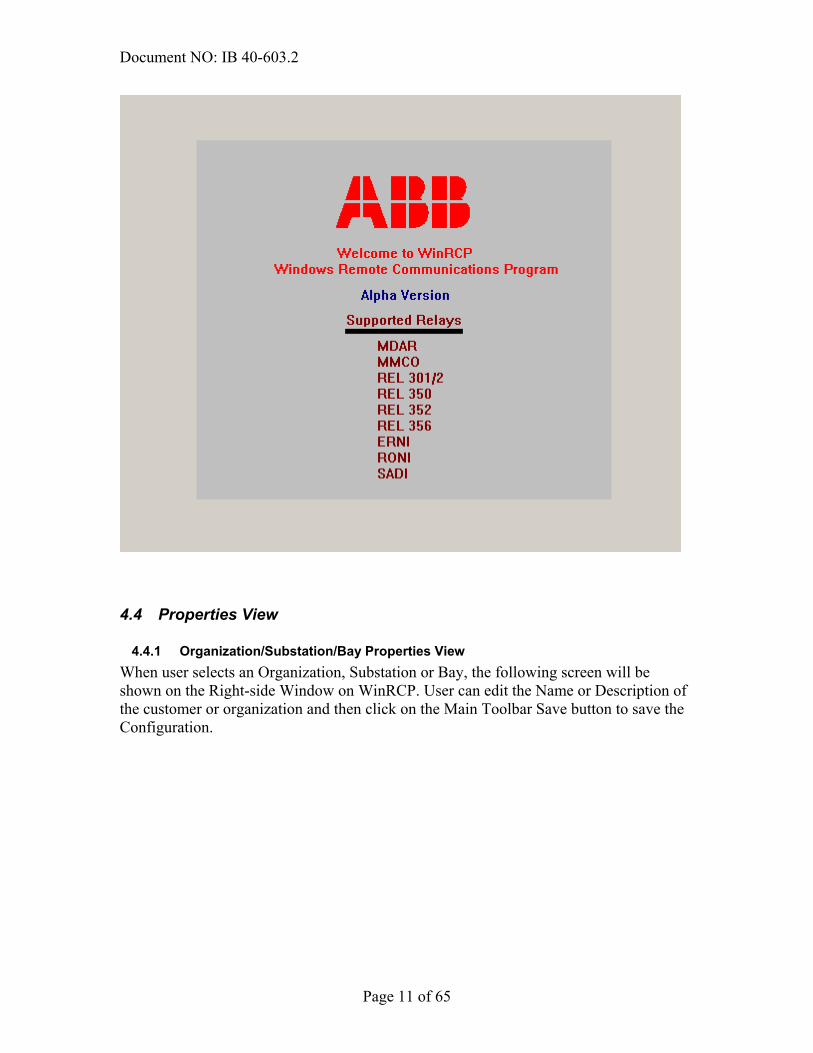
4.3 Welcome View The following diagram is the Welcome Screen of WinRCP. This screen comes up on the Right side of WinRCP Window, when the Top-Level Node in the Tree View has been selected.
Document NO: IB 40-603.2
Page 11 of 65
4.4 Properties View
4.4.1 Organization/Substation/Bay Properties View When user selects an Organization, Substation or Bay, the following screen will be shown on the Right-side Window on WinRCP. User can edit the Name or Description of the customer or organization and then click on the Main Toolbar Save button to save the Configuration.

Document NO: IB 40-603.2
Page 12 of 65
4.4.2 IED Properties View When user selects any IED Tree Item in the Configuration Tree, the following screen will be shown on the Right-side Window. User can edit the properties of the IED and save the Configuration by clicking the Main Toolbar Save button.
Name of the Organization/Substation/Bay
Description of the Organization/Substation/Bay. This is a multi-line Edit-box. CTRL+Enter key allows user to move to next line

Document NO: IB 40-603.2
Page 13 of 65
4.4.3 IED Settings Data View (IED Data View) When user selects any child item (leaf nodes) under an IED Tree Item in the Configuration tree, generally, the following type of screen will be shown on the Right-side Window. Based on the selected Item, WinRCP enables the appropriate buttons (New, Save, Open, Get, Send, Compare and Exit Password Mode) at the top of the screen. The typical table (Grid) below has 6 columns:
• Serial Number: Row Number (0-based) • Name: Name of the Data Item • Value: Value of the Data Item (If Send button is enabled, the Value cells become
editable) • Units: Unit of the Data Item (wherever applicable) • Range: Data Value Range (wherever applicable)

Document NO: IB 40-603.2
Page 14 of 65
• Increments: If the Data Value is editable, this column indicates the permissible level.. (for example, if the current Data Value is 30, Range is [30,5000] and the Increment is 5, then the only allowable values are 30,35,40,45 …4985,4990,4995,5000)
Settings view of the selected IED
Document NO: IB 40-603.2
Page 15 of 65
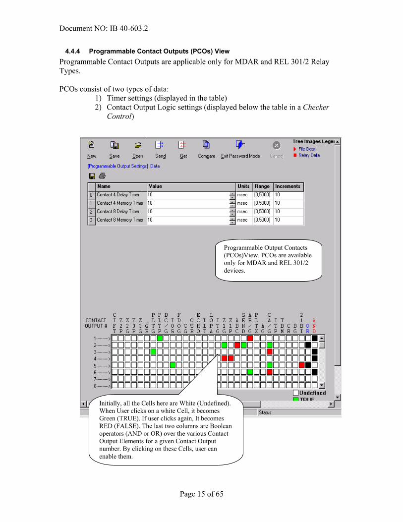
4.4.4 Programmable Contact Outputs (PCOs) View Programmable Contact Outputs are applicable only for MDAR and REL 301/2 Relay Types. PCOs consist of two types of data:
1) Timer settings (displayed in the table) 2) Contact Output Logic settings (displayed below the table in a Checker
Control)
Programmable Output Contacts (PCOs)View. PCOs are available only for MDAR and REL 301/2 devices.
Initially, all the Cells here are White (Undefined). When User clicks on a white Cell, it becomes Green (TRUE). If user clicks again, It becomes RED (FALSE). The last two columns are Boolean operators (AND or OR) over the various Contact Output Elements for a given Contact Output number. By clicking on these Cells, user can enable them.

Document NO: IB 40-603.2
Page 16 of 65
4.4.5 Intermediate Target Data View The following is a snap-shot of a typical Intermediate Target Data screen.
4.5 SADI Transparent (ASCII) Mode View The SADI Device has a function (Tree Item) named – 10 Byte Mode. When user selects this Item in the Tree View, the following screen will come up on the Right Side of the WinRCP Window. The following diagram shows how SADI will be used to connect WinRCP to a 3rd Party ASCII Device: SADI Device acts as a Gateway between WinRCP and the Host Relay
Intermediate Target Data View. Intermediate Target Data is available only for MDAR and REL 301/2 devices.
Host Relay e.g. DLP
SADI BIRT WinRCP PC RS-232
INCOM Network
RS-232
Document NO: IB 40-603.2
Page 17 of 65
4.6 Menu Items & Toolbar Buttons
4.6.1 Main Menu Items The following are the Main Menu Sections of WinRCP.
• File This section contains all the Configuration and Print Related Menu Items • Communications This section contains the Relay Communications
(Serial/Modem/Telnet) Menu Items • Passwords This section contains the Menu Items to change Passwords • Oscillography Tools This section contains the Oscillography Tools Menu
items
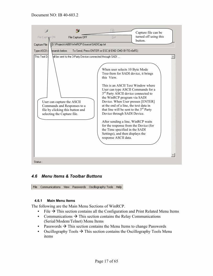
When user selects 10 Byte Mode Tree-Item for SADI device, it brings this View. This is an ASCII Text Window where User can type ASCII Commands for a 3rd Party ASCII device connected to the WinRCP program via SADI Device. When User presses [ENTER] at the end of a line, the text data in that line will be sent to the 3rd Party Device through SADI Device. After sending a line, WinRCP waits for the response from the Device (for the Time specified in the SADI Settings), and then displays the response ASCII data.
User can capture the ASCII Commands and Responses to a file by clicking this button and selecting the Capture file.
Capture file can be turned off using this button.

Document NO: IB 40-603.2
Page 18 of 65
4.6.2 File Menu Items
4.6.3 Communications Menu Items
4.6.4 Passwords Menu Items
4.6.5 Oscillography Tools Menu Items
Closes the current configuration and creates New Empty configuration.
Opens the Configuration from a file
Saves the current configuration to a file
This section of menu items can be used to add Organization/Substation/Bay and various Relays supported by WinRCP
Deletes the selected Tree-Item (Organization/Substation/Bay/IED)
Brings up the Print layout definition dialog-box, where user can configure print layouts and save them to files
Print Preview and Print items let user print the printable data for the selected IED node
This Item lets user configure the Serial Ports for both direct and Modem communications
Connects to the Relay selected in the Tree View.
Disconnects from the currently selected Relay
This section lets user make a Telephone call and hang-up the currently active Telephone connection
This item brings up the Telnet window
Changes the Master Password
Changes the Settings Password
This item lets user configure an External Oscillography Viewer program.
Executes the Configured Oscillography Viewer to view the COMTRADE OSC files retrieved by WinRCP
This Item lets user to convert RCP-generated OSC file into COMTRADE Format.

Document NO: IB 40-603.2
Page 19 of 65
4.6.6 Tool-bar Buttons This section describes briefly what each of the tool-bar buttons mean.
4.6.7 Properties View – Buttons This section describes the meaning of the various buttons in the Properties View.
Closes the current configuration and creates New Empty configuration.
Opens the Configuration from a file
Saves the current configuration to a file
This Item lets user configure the Serial Ports for both direct and Modem
Brings up the Print layout definition dialog-box, where user can configure
Print Preview item lets user preview the printable data for the selected IED
Print item lets user print the printable data for the selected IED.
Connects to the Relay selected in the Tree View.
Disconnects from the currently selected Relay
This button lets user make a Telephone call
This button lets user disconnect the currently active Phone connection.
This button lets user bring up the Telnet window in order to connect to the telnet Servers (Telnet Gateways)
Applicable for Settings and PCOs. Resets the settings from Template file (Default settings)
Applicable for Settings, PCOs and Fault Operation Summary Data. Saves the Data to a file.
Applicable for Settings, PCOs and Fault Operation Summary Data. Opens and displays the data from a file
Applicable for Password Commands. Sends the settings data / command to the IED.
Applicable for all the data that can be retrieved from the IED. Retrieves the Data from the IED.
Applicable for Settings, PCOs. Compares the Settings Data from the Grid to the Data from already saved file.
Exits from Passwords Commands. If User wants to enter into password commands again, he has to supply a password
Cancels the Get/Send command currently being processed.

Document NO: IB 40-603.2
Page 20 of 65
5 Configuration This section describes how to configure Relays and other items in WinRCP.
5.1 Adding an Organization, Substation, Bay or an IED These can be configured using either Pop-up menus or the Main menu as shown below: Step 1: Use Pop-up menu (or Main menu) to select what needs to be added (Organization/Substation/Bay/IED) right-click with the mouse. Step 2: Configure the Properties of the added Item. Step 3: Once finished configuring the Properties, use the Tool-bar Save Button to save the Configuration to a file. For more details see example in Appendix D.
Saves the current Grid Contents to a Text file
Prints “as is” the Grid which is currently being displayed .

Document NO: IB 40-603.2
Page 21 of 65
Using Pop-up Menu Using the main Menu
5.2 Configuring an IED This section describes the Configuration properties of an IED in detail. Please refer to the following diagram to identify the various Configuration sections.

Document NO: IB 40-603.2
Page 22 of 65
5.2.1 Identification This section has the following two properties:
1) Name: The unique name of the IED. This name appears in the Tree-View for the IED.
2) Description: One-line description of the IED.
5.2.2 Version Information This section allows the user to indicate which version of the IED is called for. User must select one of the available versions from the list.

Document NO: IB 40-603.2
Page 23 of 65
5.2.3 Model Information This section contains the Model Information of the IED. Each of the supported IEDs comes with various Options. Here, the user must indicate the appropriate purchased Options.
5.2.4 Device Parameters This section contains the following device (IED) parameters:
1) Unit ID: If the IED is connected via BIRT, user must specify the Unit ID of the IED. Unit ID for a Device can be found in the back of the Device (the rotating 3-digit (Hex) number). If IED is directly connected, user must set this parameter to 0.
2) Metered AC Values Polling Frequency: This Parameter tells at what frequency the Metered AC Values (Real-time Data) for the currently selected device will be polled and updated on the screen. If user sets this parameter to 0, Automatic polling will be disabled (User must manually update by the Get button)
5.2.5 Communications Choice This section contains all the available communications choices. User must pick one of the following choices.
1) Serial: WinRCP is connected to the device using RS-232 Serial cable 2) Internal Modem: WinRCP is connected to the device through an Internal Modem
installed in the PC. 3) External Modem: WinRCP is connected to the device through an external Modem
connected to the PC. 4) Telnet: WinRCP is connected to the device via Telnet Terminal Gateway (such as
SEL 2030 or IP-Server). (Communications choices above are explained in detail in Section 8)

Document NO: IB 40-603.2
Page 24 of 65
Communications section.
5.2.6 Serial COMM Configuration This section describes the Serial Communications Parameters.
1) COMM Port: Before configuring this parameter, user must configure at least one Direct Serial Port through the Communications Configure Ports menu item. If user fails to do this, he or she will get the following message:
2) Baud Rate: Allowed Baud rates are – 1200,2400,4800,9600,19200. User must
select an appropriate Baud rate that matches the Device’s Baud rate
5.2.7 Code Operated Switch If WinRCP is connected to a device through a Code Operated Switch (or a Port Switch like SEL 2020), the user must configure the following section.
1) Using a Code Operated Switch: Click this check-box if using COS or a Port Switch
2) Initialization Command Count: Sets the number of Initialization Commands required to accomplish the Port Switch. This is the number of sets of (Command, Delay and Response) fields which will be created automatically. For example, the above diagram shows that only one ‘Initialization Command’ (Command String: “PORT 12”) is required. This example uses SEL 2020 as a Port Switch.
3) Initialization Command: The ASCII Command sent to the COS/Port Switch to accomplish a switch to the device currently being configured. All of the printable ASCII Codes and CTRL Key are allowable characters. For CTRL Key, use ‘^’ character.
4) Initialization Delay: This indicates the delay in seconds waiting for a response for the Initialization Command.

Document NO: IB 40-603.2
Page 25 of 65
5) Initialization Response: The expected Response in order to proceed to the next Initialization Command. If left blank, WinRCP will display the response it received for the Initialization Command and allow user to continue or stop.
6) Termination Command Count: This parameter is used to set how many Termination Commands are required to accomplish the termination of the current Active Transparent Mode of the COS/Port Switch.
7) Termination Command: This is similar to the Initialization Command. In the above example, CTRL+D (^D) is used as the Termination Command
8) Termination Delay: This is similar to Initialization Delay. 9) Termination Response: This is similar to Initialization Response.
5.2.8 Modem Properties When the device is connected using a Modem, the user must configure the dialing properties for the Modem in this section.
1) Direct Dialing
While using a direct dial number, the user must enter the dial number (without any spaces or dashes) as shown in the above diagram. 2) Long Distance Direct Dialing or Dialing using Calling Card

Document NO: IB 40-603.2
Page 26 of 65
While using a Long distance number or a Calling Card, the user must follow these steps:
a) Click the ‘Using Calling Card’ check-box b) Enter the First number to be dialed (ex: 1-800 number of the calling card
company) c) Select the waiting time (e.g.: 10 seconds) d) Enter the next number to be dialed (ex: 0 followed by the 10-digit
telephone number) e) Select the waiting time (e.g.: 8 seconds) f) Enter the next number to be dialed (e.g.: PIN number) g) Select the waiting time (e.g.: 8 seconds) h) Enter the next number (e.g.: an extension number 4312) i) Select ‘Done’.
Note: these steps are only an example of how to dial a long-distance number with a 4-digit extension using a SPRINT Calling card. The user can enter any number of sets (number followed by delay) required to dial into the remote Modem to which the device is connected.
5.2.9 Telnet Properties When the device is connected to a Telnet Terminal Server like SEL 2030 or IP-Server, WinRCP uses Telnet client functionality to establish transparent communications to the Device through the Terminal Server. In this case, the user must configure the following Telnet Properties.

Document NO: IB 40-603.2
Page 27 of 65
NOTE: We recommend using the Manual setup of the Telnet, which gives the user more control of the setup process..
1) Show Telnet Windows (Manual Setup): If user clicks this check box, a Telnet client window will pop-up when attempting to connect to the Device.
2) Host Name/ IPAddress: Host name or IP Address of the Terminal Server (ex: SEL 2030).
3) User Name: Telnet Account user name 4) Password: Password for the above user name 5) Initialization Commands, Termination Commands: These commands are similar
to the Code Operated Switch Commands described in 5.2.7 Code Operated Switch
5.3 Configuring Serial / Modem Ports The user can configure up to two Serial Ports using the Communications Configure Ports menu item.
In the above diagram, COM1 and COM2 are configured as Direct and Modem types respectively. User can (optionally) specify the Initialization String for the Modem Type COM Ports.

Document NO: IB 40-603.2
Page 28 of 65
5.4 Configuring Print Layout Settings WinRCP lets the user print various data available in the IED’s – such as Settings, Programmable Contact Outputs, Recloser Settings and Fault operation Summary. User can define Print Layouts and save them permanently as Layout files. Using File Print Page Layouts… menu item - user can invoke the following dialog-box. User can define the header and footer for the printable data in the using this dialog-box. Up to 3 lines of Header and 3 lines of footer is allowed. Each line can contain left-aligned, center-aligned and right-aligned texts. The following dialog-box allows the user to configure the Header and Footer lines using text-boxes.

Document NO: IB 40-603.2
Page 29 of 65
User can enter any text in the text boxes or select the text from using the button.
In the above dialog box, user can select an Item to be inserted into the header/footer.
In the above dialog box, users can add/modify/delete custom Items. Each custom Item consists of an Item Name and the associated Text. When user selects the Item, the associated Text goes to the Printer.
Opens a layout file Saves the current Layout to a file
Configures Custom Items
Brings up this dialog-box Brings up this dialog-box

Document NO: IB 40-603.2
Page 30 of 65
The following pre-defined items (System Items) can be placed in the Header or Footer.
• DATE: Current Date at the time of printing. • DATE & TIME: Current Date & Time at the time of printing. • PAGE: Page number • PAGE/TOTAL: Page number / Total number of Pages • RelayName: Relay Name (Configured Name from the IED Properties) • RelayName & Version: Relay Name and Relay Version • TITLE: Title of the date being printed

Document NO: IB 40-603.2
Page 31 of 65
6 Settings All the Relay Types supported by WinRCP (except ERNI) have Settings. This section describes various user operations on Relay Settings.
Edited (Modified) settings appear in a different color (Orange color) then the un-edited Settings (White color)
Various operations on Settings

Document NO: IB 40-603.2
Page 32 of 65
6.1 Creating New Settings for an IED – NEW Every Relay has one or more Template files (each Template File uniquely identifying a Version of the Relay). When the user clicks on the New button, WinRCP populates the Settings Table with the (default) values from the corresponding Template File for the selected IED.
User can create new settings (fromTemplate file) for an IED by clickingon this New Button, in the Settingssection of the Password Commands.

Document NO: IB 40-603.2
Page 33 of 65
6.2 Settings to a File – SAVE The following diagram shows how a user can save the settings to a file from the Table.
User can save the present settings from the table by clicking on the Save button. “Save settings to a file” is allowed only from Password Commands

Document NO: IB 40-603.2
Page 34 of 65
6.3 Open Settings from a File – OPEN The following diagram shows how a user can open settings from a file into the Table.
User can open (for viewing) settings from an already saved file using this button. “Open settings from a file” is allowed only from Password Commands
Document NO: IB 40-603.2
Page 35 of 65
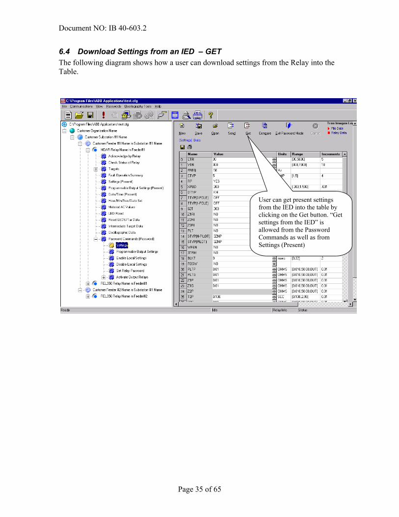
6.4 Download Settings from an IED – GET The following diagram shows how a user can download settings from the Relay into the Table.
User can get present settings from the IED into the table by clicking on the Get button. “Get settings from the IED” is allowed from the Password Commands as well as from Settings (Present)
Document NO: IB 40-603.2
Page 36 of 65
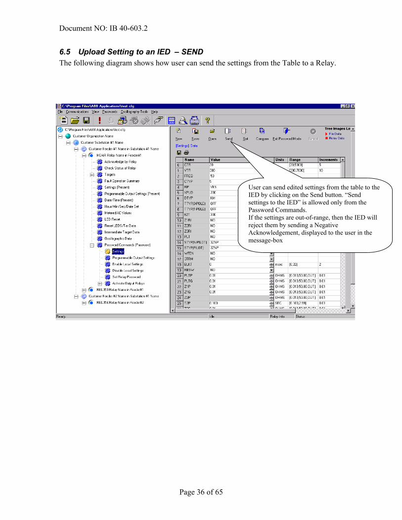
6.5 Upload Setting to an IED – SEND The following diagram shows how user can send the settings from the Table to a Relay.
User can send edited settings from the table to the IED by clicking on the Send button. “Send settings to the IED” is allowed only from the Password Commands. If the settings are out-of-range, then the IED will reject them by sending a Negative Acknowledgement, displayed to the user in the message-box

Document NO: IB 40-603.2
Page 37 of 65
6.6 Compare Settings from a File to the Settings from an IED – COMPARE The following diagram shows how a user can compare the settings in the Table to the settings in an already saved file.
User can compare the settings in the Table with the saved settings from a file by clicking the Compare button. “Compare settings” is allowed only from the Password Commands. Differences will be displayed in a tabular format.

Document NO: IB 40-603.2
Page 38 of 65
6.7 Password Mode The following diagram shows how a user can exit from the Passwords Mode
User can exit the Password mode by clicking on the Exit Password Mode button.

Document NO: IB 40-603.2
Page 39 of 65
6.8 Settings Inter-operability between RCP and WinRCP Settings files saved by WinRCP are backward compatible (i.e., Settings files saved through WinRCP can be opened through DOS-RCP and settings files saved through DOS-RCP can be opened through WinRCP).
6.9 Settings files – naming convention The following are the file extensions (3-letters after the dot in the file name) used for the supported Relays. These extensions are compatible with DOS-RCP program generated Settings files. IED (Relay) Type Extension MDAR set MDAR Programmable Contact Output Settings spt MMCO sct REL 301/2 (Protection) s3t REL 301/2 (Recloser) s3r REL 301/2 Programmable Contact Output Settings s3p REL 350 smt REL 352 sph REL 356 spi SADI sgt RONI srt

Document NO: IB 40-603.2
Page 40 of 65
7 Security WinRCP Program is protected from unauthorized users through Passwords at various levels.
7.1 Description of the Master Password WinRCP is protected by a Password, which is called the Master Password. The Master Password is the Password supplied by the user at the time of Installation of WinRCP (shown in the following Installation dialog-box). In order to run the WinRCP Application, user MUST have access to the Master Password.
7.2 Description of the Settings Password The Master Password allows a user to View the Relay Data using WinRCP. However, if a user wants to Send any Commands to the Relays or Send settings to the Relays, he or she MUST have access to the Settings Password. In order to enter into the Password specific commands in the WinRCP Configuration Tree View, user must provide the Settings Password. As with the Master Password, the Settings Password is supplied by the user at the time of Installation of WinRCP (shown in the above Installation dialog-box)
Master Password
Settings Password

Document NO: IB 40-603.2
Page 41 of 65
7.3 Description of the Relay (IED) Password The Relay Password is the Password within the Relay, which is used by the Relay to protect from unauthorized upload of Settings and executions of commands. WinRCP does NOT maintain this password. This password will be supplied by ABB along with the Relay.
7.4 Changing the Master Password In order to change the Master Password, user must select the Password Change Master Password menu item. The following dialog-box will appear, allowing the user to change the Master Password for the WinRCP Program.
7.5 Changing the Settings Password When the user selects the Password Change Settings Password menu item, the following dialog-box will pop-up, where user can change the Settings Password for the WinRCP Program.

Document NO: IB 40-603.2
Page 42 of 65
7.6 Changing the Relay (IED) Password Every Relay supports a Command called Set Relay Password (typically found in the WinRCP Configuration Tree at IED Password Commands (Password) Set Relay Password). A user can change the Relay Password by using this command. First, select Tree Item “Password Commands (Password) Set Relay Password)” and then click on the Send button on the right side window. In the pop-up dialog-box, user must supply the old Relay Password along with the new Relay Password. If the user forgot the old Relay Password, he or she must restart (Power off and on) the Relay. In the first 15 minutes of the restarting, the Relay will accept the string “PASSWORD” as the Password.
7.7 Forgotten Master Passwords or Settings Passwords If Master or Settings Passwords are forgotten – the user must reinstall WinRCP from the Installation CD or Floppy Diskette in order to proceed. For this reason, the Installation Disks must be stored in a secure and easily accessible place.

Document NO: IB 40-603.2
Page 43 of 65
8 Communications This section illustrates the various Communications Architectures possible with WinRCP.
8.1 Direct Serial Communication
8.2 Multi-drop via BIRT
8.3 Direct Communications using Modems The modem attached to the WinRCP computer can be either an internal or an external Modem (as shown below). Internal Modem – the Modem is directly installed in the PC. External Modem (without driver installed) – Modem is attached to the PC’s COMM Port and NO driver is installed in the PC for that driver. External Modem (with driver installed) – Modem is attached to the PC’s COMM Port (or Modem pool connected to the PC over LAN) for which the appropriate Modem Driver (or Service) is installed.
RS-232 Null-Modem Cable
RS-232 Straight through Cable
BIRT
Telephone Network
Document NO: IB 40-603.2
Page 44 of 65
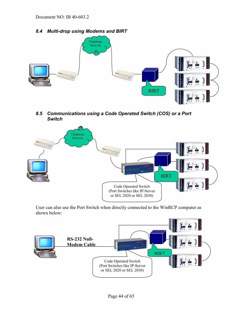
8.4 Multi-drop using Modems and BIRT
8.5 Communications using a Code Operated Switch (COS) or a Port Switch
User can also use the Port Switch when directly connected to the WinRCP computer as shown below:
BIRT
Telephone Network
Code Operated Switch (Port Switches like IP-Server or SEL 2020 or SEL 2030)
Telephone Network
BIRT
RS-232 Null-Modem Cable
Code Operated Switch (Port Switches like IP-Server or SEL 2020 or SEL 2030)
BIRT

Document NO: IB 40-603.2
Page 45 of 65
8.6 Telnet Communications Please refer to the Section 10 Appendix A – Using IP-Server as a Telnet Gateway for Remote Communications for a detailed description of how to use an IP Server as a Telnet Gateway to communicate to remote devices. IP-Server acting as a Telnet
Gateway (you can also use SEL 2030 as the Telnet
Gateway)
LAN or Internet (telnet Connection)
BIRT

Document NO: IB 40-603.2
Page 46 of 65
9 Relay (IED) Operations A detailed description of Relay Operations is outside the scope of this document. It is therefore recommended that users refer to the Relay Manuals. However, certain unique features of the Relay Operations are described in this section.
9.1 Settings All the supported Relays … support Settings (except for the ERNI). Still, based on the Model & Version of a Relay, some of the settings may be disabled. These disabled settings will be visible (gray color) as shown in the following diagram. User can only download (Get) settings from the Relay in the non-Password Mode. In order to do other operations like Save, Open, Send and Compare settings, user must enter into the Password Mode by clicking on the Password Commands (Password) Tree Item. To upload settings, follow these 3 steps:
a) Send Settings b) Wait for the Settings to be saved into EEPROM c) Get Settings from the Relay and compare with the sent settings to verify
that Send Settings is successful.
Disabled settings for REL356 relay without optional Back-up distance protection

Document NO: IB 40-603.2
Page 47 of 65
9.2 Real-Time Data WinRCP provides a continuous polling mechanism for Metered AC Values (Real-time Data) for all IEDs. The user can configure the Polling Frequency (found in the IED Properties under Device Parameters section). Polling Frequency can be set any value between 0 to 60000 milliseconds (i.e., Poll just once to Poll once in every minute). User can see Secondary Values by clicking the Display Secondary Values check box shown below
Use can get Primary Metered AC values by clicking this box, and then clicking Get button. If user has provided a polling frequency in IED Properties area, the next Metered AC values will be displayed

Document NO: IB 40-603.2
Page 48 of 65
9.3 Fault Operation Summary The following diagram shows the Fault Operation Summary from the Relay. Typical Fault Operation Summary consists of : Target Record Summary and OSC Record Summary Operations allowed for Fault Operation Summary consists of : Get from the Relay Save to a File from the Table (Grid) Open from a File into the Table (Grid)

Document NO: IB 40-603.2
Page 49 of 65
9.4 Oscillography The following Relays support the Oscillographic Data (Fault Recorder Data) MDAR REL 301/2 REL 350 REL 352 REL 356 WinRCP can retrieve a selected OSCillography Record and save the data in COMTRADE – ASCII Format. Users can view and analyze these files via any COMTRADE Viewers (such as WaveWin from ABB). The following diagram shows how to select and retrieve OSCillograhic Data for a Fault in the Relay.
After selecting the Oscillographic DataTree Item, user has to click Get button to retrieve OSC data
User can choose to get both Analog & Digital OSC Data - or just the Analog OSC Data for the selected Fault
All the available Faults are listed here. User has to select the desired Fault and then click OK to retrieve the OSC data corresponding to that Fault

Document NO: IB 40-603.2
Page 50 of 65
9.5 Targets Most of the Relays have a maximum of 16 Targets available. To retrieve the Target Summary for a Target, user has to select the particular target (ex: IED_REL30X Targets Target 3) in the Tree-View, and then Click on the Get button on the right-side View to get the data for that target. Wherever applicable, Primary values for Targets can also be displayed by clicking the Display Primary Values check-box.
9.6 Password Commands WinRCP provides Password Protection on specific operations for all the Relays. These operations are under the Tree Item Password Commands (Password). When user tries to expand this Tree Item, he or she will be asked to enter the Password as shown below.
Enter the settings password in this box
Password Commands - . to access the password commands section, user should enter the correct Setting Password in the dialog box

Document NO: IB 40-603.2
Page 51 of 65
10 Appendix A – Using IP-Server as a Telnet Gateway for Remote Communications
10.1 Requirements Please make sure the following hardware and software is available before proceeding further.
• WinRCP installed on a PC/laptop • Ethernet Cable • IP-Server box • At least one Relay (ex: MDAR) • BIRT (optional) • RS-232 Straight-through Cable (if connecting directly to the Relay) • RS-232 Null Modem cable (if connecting to the Relay via BIRT)
10.2 Procedure
10.2.1 Step 1: Configure the IP Addresses of the WinRCP PC and IP Server We will use the following IP Addresses for WinRCP PC and the IP Server: 10.10.10.10 IP Address of IP Server 10.10.10.12 IP Address of the WinRCP PC. 255.255.255.0 Network Mask How to set IP Address for IP Server Use a NULL Modem Serial cable to connect PC to the IP Server’s front PORT. Open Hyper Terminal on the PC. User 19200,N,8,1 as the COMM Parameters to communicate to the IP Server You will see login Prompt. Use the login: admin Use password: ptc Now, command prompt will appear on the Hyper terminal window. Use “ipcfg” command to enter into Configuration mode where you can change the IP Address of the IP Server. Follow the menu instructions to change the IP Address to 10.10.10.10 Ignore DNS address. After finishing the change, use type in “reboot” and hit [ENTER] key to restart the IP Server: Wait for 2 mins. before IP Server reboots.

Document NO: IB 40-603.2
Page 52 of 65
10.2.2 Step 2: Configure the Serial Port on IP Server Using internet explorer (or any browser), open http://10.10.10.10 (IP Address of IP Server) You will see the IP Server’s Welcome screen. Select Configuration Serial Devices menu item. You will see the Serial Device Configuration screen. Enter password (456) to edit the Configuration. Make sure that the PORT SETTINGS for the Port on IP Server (which will be used to connect to the Relay) match with the Port settings of the Relay.
10.2.3 Step 3: Connect WinRCP to IP Server using Ethernet Cable Connect WinRCP to IP Server using the Ethernet Cable
10.2.4 Step 4: Connect IP Server Serial Port to the Relay using Serial Cable Connect IP Server Serial Port to the Relay using Serial Cable
10.2.5 Step 5: Run WinRCP Configure the Relay in WinRCP with Telnet as the choice of communications. Configure the Telnet Properties (in the IED Properties screen) Try connecting to the Relay. A Telnet window will pop-up with Login Prompt Use ‘admin’ as the login and ‘ptc’ as the password After successful login, you will see a prompt. Use the following command: connect <n> (where ‘n’ is the Port Number on the back) Now, click on the Hide button. WinRCP will attempt to connect to the Relay.
Document NO: IB 40-603.2
Page 53 of 65
11. Appendix B – Using SEL 2030 as a Port Switch (Code Operated Switch).
11.1 Requirements
• WinRCP installed on a PC/laptop • SEL 2030 box • 2 Relays (REL 301/2 and REL 356) • BIRT (optional) • RS-232 Straight-through Cable (if connecting SEL 2030 to the Relay via BIRT) • RS-232 Null Modem cable (if connecting SEL 2030 directly to the Relay) • RS-232 Null Modem cable (if connecting WinRCP PC to SEL 2030 front port)
11.2 Procedure
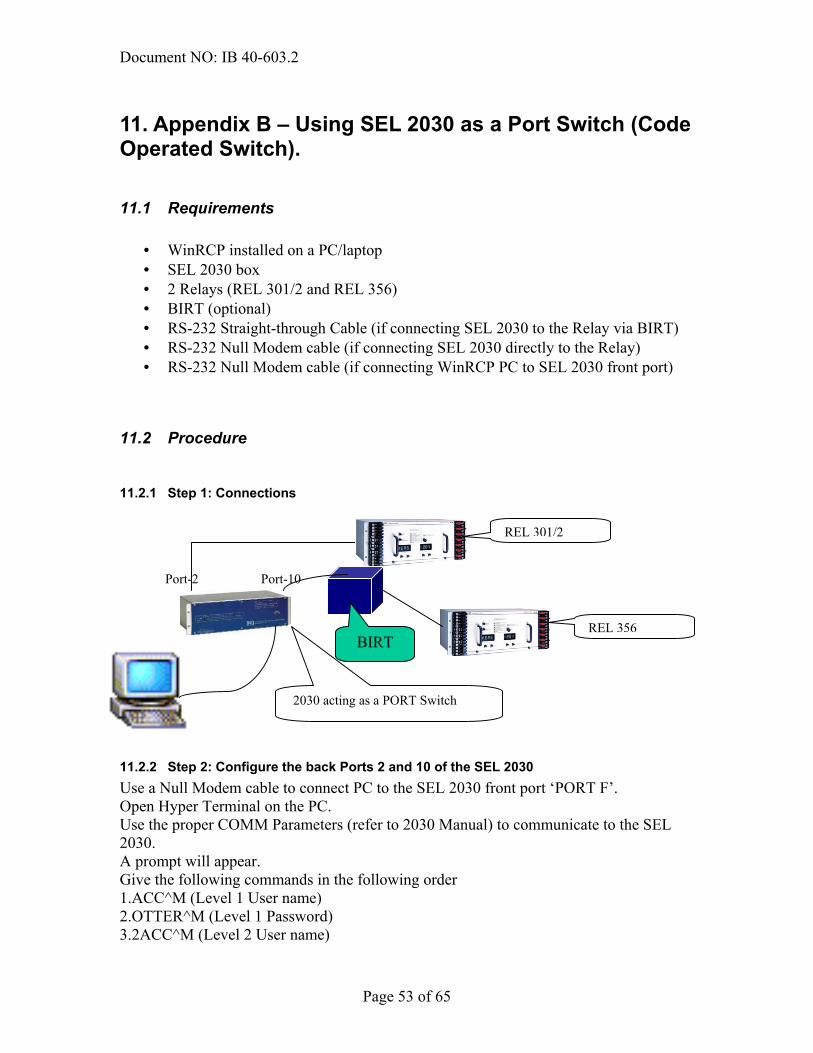
11.2.1 Step 1: Connections
11.2.2 Step 2: Configure the back Ports 2 and 10 of the SEL 2030 Use a Null Modem cable to connect PC to the SEL 2030 front port ‘PORT F’. Open Hyper Terminal on the PC. Use the proper COMM Parameters (refer to 2030 Manual) to communicate to the SEL 2030. A prompt will appear. Give the following commands in the following order 1.ACC^M (Level 1 User name) 2.OTTER^M (Level 1 Password) 3.2ACC^M (Level 2 User name)
Port-10 Port-2
2030 acting as a PORT Switch
BIRT
REL 301/2
REL 356

Document NO: IB 40-603.2
Page 54 of 65
4.TAIL^M (Level 2 Password) 5. SET PORT 2 (Command to change the back Port 2 settings) 6. SET PORT 10 (Command to change the back Port 10 settings) Steps (5) and (6) above are used to change and save the COMM settings of Port 2 and Port 10 to match with the settings of REL 301/2 Relay and BIRT respectively.
11.2.3 Step 3: Relay Configuration in WinRCP Configure the Relays (REL 301/2 and REL 356) in WinRCP with the External Modem as the choice of communications. Check the COS check box in the “ Code Operated Switch” section, and give the following Initialization Commands and Termination Commands Initialization Commands:
1. ACC 2. OTTER 3. 2ACC 4. TAIL 5. ^D (terminate any active transparent communications) 6. PORT x
Note: x is the no. of SEL 2030 port on which device is connected. (in the above example x will be 2 for REL 301/2 and 10 for BIRT)

Document NO: IB 40-603.2
Page 55 of 65
Select the appropriate Relay and
Connect to the Relay by clicking button.
12 Appendix C – Using SEL 2030 with Modems as a Port Switch (Code Operated Switch) for Remote Communications
12.1 Requirements Please make sure the following hardware and software is available before proceeding further.
• WinRCP installed on a PC/laptop • SEL 2030 • 2 Relays (REL 301/2 and REL 356) • BIRT (optional) • 2 US Hayes compatible modems • RS232 Null Modem Cable (for connecting the Modem Port on SEL2030 to the
Modem) • RS 232 Null Modem Cable (for connecting the WinRCP PC to the Modem).
`
12.2 Procedure The Procedure is exactly same as the procedure described in Appendix B, except for the Modems’ setup. Refer to SEL 2030 Manual and set up Modem Communications between the PC on which WinRCP is running and the SEL 2030 Modem Port (PORT 8) as shown in the following diagram.
Telephone Network
BIRT
2030 acting as a PORT Switch
REL 356
REL 301/2

Document NO: IB 40-603.2
Page 56 of 65
After finishing the above setup, follow the steps (2) and (3) from Appendix 2. Note: To switch the communications between REL 301/2 to REL 356 (in the above
setup), try to disconnect from the currently active Relay by clicking the button. You will see the following message box.
Click No if you want to retain the Telephone connection to the SEL 2030 (via Modems) and disconnect the currently active Relay. In this case, next time when you attempt to connect to another Relay, WinRCP will not have to dial the SEL 2030 as the Telephone connection will still be active. If you want to disconnect to the Relay and also hang up the telephone connection, you have to click on the Yes button above.

Document NO: IB 40-603.2
Page 57 of 65
13 Appendix D – Sample Configuration Assumptions for purpose of demonstration: • at Organization Level, name is ABB Organization • at Substation Level, two different substations will be named as Substation 1 and
Substation 2 • at Bay/Feeder level, Substation 1 will have three Bay/Feeders named as
Sub1Feeder1, Sub1Feeder2 and Sub1Feeder3. Substation2 will have two Bay/Feeders named as Sub2Feeder1 and Sub2Feeder2
• at IED level, SubFeeder1 will have REL356 relay, Sub1Feeder2 will have MDAR relay and Sub1Feeder3 will have REL301 relay. Sub2Feeder1 will have REL350 relay and Sub2Feeder2 will have MMCO relay.
13.1 Step 1: Add Organization After starting the WinRCP program, the Welcome View will appear:
Using the Main Menu, under File, select Add Organization. A new window will appear:

Document NO: IB 40-603.2
Page 58 of 65
On the right side under Organization Properties, Select New Organization. Use ABB Organization in New Organization field.
Save this selection under File, Save as. Now select the location where the Configuration will be stored.
Document NO: IB 40-603.2
Page 59 of 65
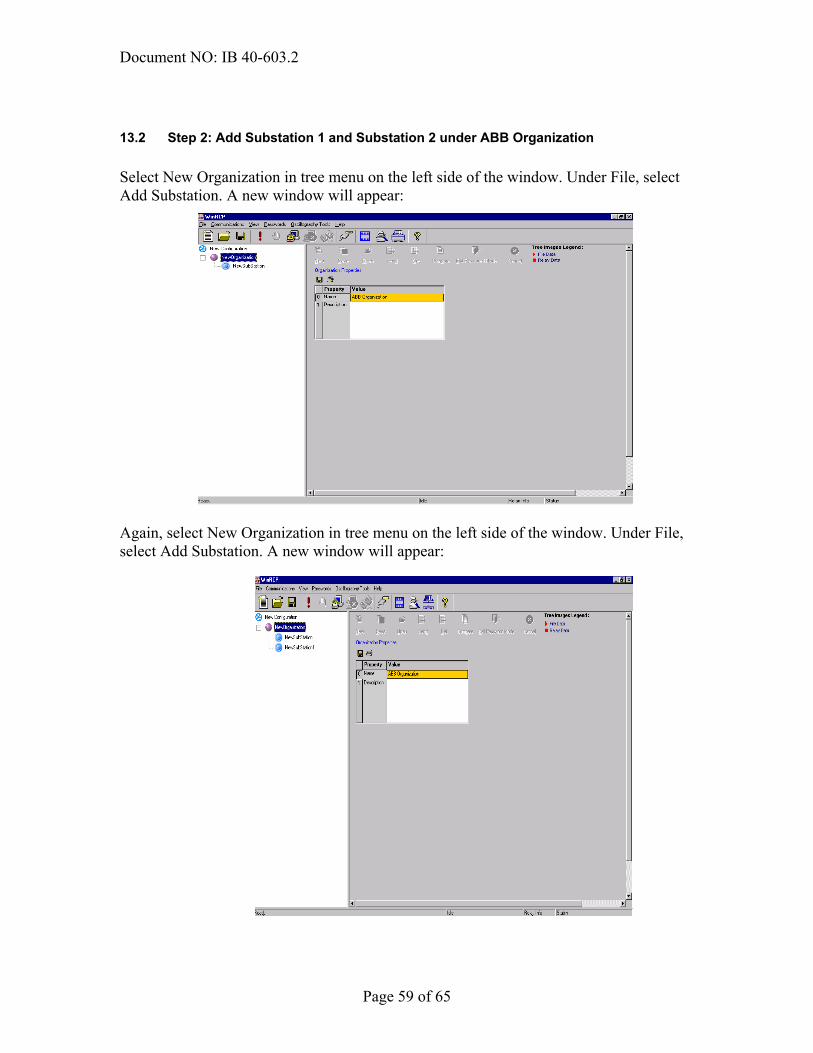
13.2 Step 2: Add Substation 1 and Substation 2 under ABB Organization Select New Organization in tree menu on the left side of the window. Under File, select Add Substation. A new window will appear:
Again, select New Organization in tree menu on the left side of the window. Under File, select Add Substation. A new window will appear:

Document NO: IB 40-603.2
Page 60 of 65
Selecting New Substation, on the right side under Substation Properties, place Substation 1 name into New Substation field. Save this selection under File, Save . Next, place Substation 2 name into New Substation1 field.. Save this selection under File, Save. A new window will appear:

Document NO: IB 40-603.2
Page 61 of 65
13.3 Step 3: Add Sub1Feeder1, Sub1Feeder2 and Sub1Feeder3 under Substation 1 and Sub2Feeder1 and Sub2Feeder2 under Substation 2 Select Substation 1 in tree menu on the left side of the window. Under File, select Add Bay. Repeat this two more times. Next, select Substation 2 in tree menu on the left side of the window. Under File, select Add Bay. Repeat this one more time. A new window will appear:
Select NewBay on the left side of window. On the right side under Bay Properties, place Sub1Feeder1 name into NewBay field. Save this selection under File, Save . Next, place Sub1Feeder2 name into NewBay1 field. Save this selection under File, Save. Similarly place Sub1Feeder3 name into NewBay2 field. Save this selection under File, Save. Similarly, under Substation 2 there should be NewBay and NewBay1. NewBay will be renamed as Sub2Feeder1. Save this selection File, Save. NewBay1 will be renamed as Sub2Feeder2. Save this selection File, Save. A new window will appear:

Document NO: IB 40-603.2
Page 62 of 65

Document NO: IB 40-603.2
Page 63 of 65
13.4 Step 4: Add REL356 relay under Sub1Feeder1 in the Substation1 Select Sub1Feeder1 in tree menu on the left side of the window. Under File, select Add IED of Type. Select REL356 relay. The window will look like this:
IED_REL 356 may be changed with any name. Similarly, other IED’s can be added under different Bay/Feeder.

Document NO: IB 40-603.2
Page 64 of 65
Customer Feedback report
ABB Inc. would appreciate your comments on this product. Please grade the following questions by selecting one alternative per category. Your answer will enable us to improve our products. How do you grade the quality of this product? Excellent Poor Total impression Usability Functionality Comments: How do you grade the quality of this product? Excellent Poor Total impression Layout Illustration Readability Easy to find Content structure Comments:

Document NO: IB 40-603.2
Page 65 of 65
Suggestions for product improvements: Please send this report to: Author’s address: ABB Inc. ABB Inc. 7036 Snowdrift Road 4300 Coral Ridge Drive Allentown, PA 18106 Coral Springs, FL 33065 Fax: (610) 395-1055 Fax: (954) 345-5329 E-mail:[email protected]