user's manual powercube - trinity energy … 39 4.1 modbus rtu on rs485 port 39 4.2 data...
TRANSCRIPT

POWERCUBEElectrical System Monitor
USER'S MANUAL
RS485 toRS232
PowerCube
RS485 toRS232
PowerCube
RS232 cable
POWERCUBE
POWERCUBE

POWERCUBEElectrical System Monitor
This document contains the latest technical information about PowerCube which is a micro-controller based Electrical System Monitor. The product PowerCube is sophisticated electronic equipment, and the user is advised to read this User's Manual carefully before attempting to install or operate the equipment.
Published on: 11/11/2009Document Version: 1.0
USER'S MANUAL
PowerCube – Operational Manual
TRINITY
Warranty statementTrinity warrants to the original retail purchaser of the Trinity product enclosed with this limited warranty statement that the product, if purchased new and used in the India conforms to the manufacturer's specifications and will be free from defects in workmanship and materials for a period of one year from the date of original purchase, unless expressly stated otherwise by Trinity, in a written format.
Should your Trinity product prove defective during the warranty period, please bring the product securely packaged in its original container or an equivalent, along with proof of the date of original purchase, to our Trinity Dealer or Factory. You are responsible for all costs (shipping, insurance, travel time) in getting the product to the service location. Trinity will, at its option, repair or replace on an exchange basis the defective unit, without charge for parts or labor. When warranty service involves the exchange of the product or of a part, the item replaced becomes Trinity property. The replacement unit may be new or refurbished to the Trinity standard of quality, and at Trinity's option, the replacement may be another model of like kind and quality. Trinity's liability for replacement of the covered product will not exceed the original retail selling price of the covered product. Exchange or replacement products or parts assume the remaining warranty period of the product covered by this limited warranty.
What This Warranty Does Not Cover:This warranty does not apply to refurbished or reconditioned products. This warranty covers only normal use in India. This warranty does not cover damage to the Trinity product caused by parts or supplies not manufactured, distributed or certified by Trinity. This warranty is not transferable. This warranty does not cover third party parts, components or peripheral devices added to the Trinity product after its shipment from Trinity. Trinity is not responsible for warranty service should the Trinity label or logo or the rating label or serial number be removed or should the product fail to be properly maintained or fail to function properly as a result of misuse, abuse, improper installation, neglect, improper shipping, damage caused by disasters such as fire, flood, and lightning, improper electrical current, interaction with non-Trinity products, or service other than by an Trinity Authorized Service.
The warranty and remedy provided above are exclusive and in lieu of all other express or implied warranties including, but not limited to, the implied warranties of merchantability or fitness for a particular purpose. In the event, the remedies above fail, Trinity's entire liability shall be limited to a refund of the price paid for the Trinity product covered by this limited warranty. Except as provided in this written warranty, neither Trinity Energy Systems Pvt. Ltd. nor its affiliates shall be liable for any loss, inconvenience, or damage, including direct, special, incidental, or consequential damages, resulting from the use or inability to use the Trinity product, whether resulting from breach of warranty or any other legal theory.
PowerCube – Operational Manual
TRINITY
Table of Contents
1.0 Introduction............................................................................11.1 Main features available in this model ...............................21.2 Technical Specifications .................................................31.2.1 Input Specifications ......................................................51.2.3 Output Specifications ....................................................5
2.0 Installation and commissioning...............................................62.1 3P4W mode installation .................................................62.2 3P3W mode installation .................................................72.3 BACK VIEW OF THE UNIT ..............................................92.4 CAPACITOR PANEL CONNECTION SCHEME .....................102.5 RS485 CONNECTIONS .................................................11
3.0 Operational Details................................................................12
Switching Delay, Target PF and Second Target PF. ..........19
..........................................253.1.27 Selecting Control Device ..............................................25
3.1 Programming Mode .....................................................133.1.1 Selecting Installation types ..........................................133.1.2 Setting the PT Primary and PT Secondary.......................143.1.3 Setting Main CT Primary and CT Secondary ....................143.1.4 Setting Capacitor CT Primary and CT Secondary .............153.1.5 Setting Date and Time.................................................153.1.6 Setting Log Duration ...................................................163.1.7 Selecting Demand Window and Demand Interval.............163.1.8 Selecting RS232 Baudrate for data downloading..............163.1.9 Selecting the RS-485 Baudrate .....................................173.1.10 Entering the Unit Address ............................................173.1.11 Changing the Password................................................173.1.12 Setting the Event Number, Event parameter, Event
Value, Event Seconds and Event On ..............................183.1.13 Setting the Relay, Control Stages, Control Action, On Delay,
3.1.14 Setting the Alarm, Relay number, Alarm parameter, Alarm value, Alarm Delay, Alarm Hysteresis and Alarm On ..20
3.1.15 Setting Back Light On Time ..........................................223.1.16 Setting a Digital Input .................................................223.1.17 Resetting the Energies.................................................223.1.18 Resetting the Demand Power........................................233.1.19 Resetting Logs............................................................233.1.20 Resetting Run Time.....................................................233.1.21 Resetting Events.........................................................233.1.22 Resetting Minimum and Maximum.................................243.1.23 Resetting the Master for whole parameter counters .........243.1.24 Setting Scroll Page Time ..............................................243.1.25 Setting Daily Auto Sense .............................................253.1.26 Setting Manual Auto Sense
...
PowerCube – Operational Manual
TRINITY
4.0 Communication........................................................................394.1 MODBUS RTU on RS485 port...........................................394.2 Data Logging and RS232C ..............................................404.2.1 Installing the RS232 software .........................................414.2.2 Logger Window Utility ....................................................434.3 Handling the RS232 Logger ............................................444.3.1 Setting COM number and Baudrate ..................................444.3.2 Retrieving the logged data..............................................444.3.3 Setting KWh Consumption for any particular time ..............454.3.4 Setting a printer to export the data..................................464.3.5 Closing the Window for RS232 Logger ..............................464.3.6 Exporting Min/Max Event Values with Event Occurrence...........464.3.7 Exporting the System Data .............................................474.3.8 Exporting Odd Harmonics Data........................................484.3.9 Setting a Histogram.......................................................494.3.10 Setting a Trending Graph................................................504.3.11 Displaying a Graph ........................................................514.3.12 Setting a Color on Graph ................................................51
5.0 Control Outputs .......................................................................535.1 Relays for Alarm action ..................................................535.2 Demand Management with Alarm mode ...........................555.3 PF correction ................................................................56
Appendix A ...................................................................................60Address map for RS485 for the various parameters Installation in 3P4W and 3P3W.......................................60
3.2 Run Mode.....................................................................263.2.1 Run Mode in 3P4W ........................................................283.2.2 Run Mode in 3P3W ........................................................38
PowerCube – Operational Manual
TRINITY
1.0 Introduction
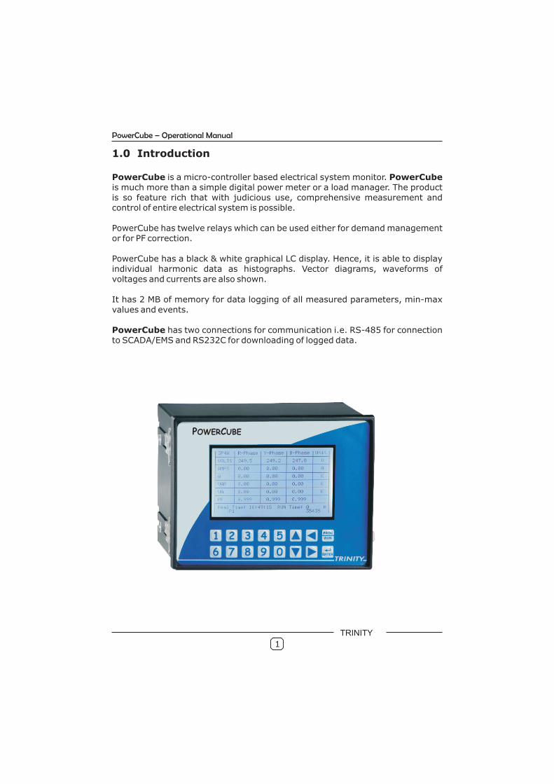
PowerCube is a micro-controller based electrical system monitor. PowerCube is much more than a simple digital power meter or a load manager. The product is so feature rich that with judicious use, comprehensive measurement and control of entire electrical system is possible.
PowerCube has twelve relays which can be used either for demand management or for PF correction.
PowerCube has a black & white graphical LC display. Hence, it is able to display individual harmonic data as histographs. Vector diagrams, waveforms of voltages and currents are also shown.
It has 2 MB of memory for data logging of all measured parameters, min-max values and events.
PowerCube has two connections for communication i.e. RS-485 for connection to SCADA/EMS and RS232C for downloading of logged data.
1
PowerCube – Operational Manual
POWERCUBE
TRINITY

1.1 The main features available in this model
Comprehensive Measurement:
All readings are True RMS measurementsFast, real-time cycle by cycle measurement, at 80 samples/cycleFour quadrant readings (Power and Power Factor)Min. /Max. ValuesKVA and KW Demands including predictive PKW and PKVA demand.Odd Harmonics up to 29th of individual Voltage, and Current Waveforms including THDMeasurement of all three voltages - phase to phase and phase to neutral, all three currents, power factors - phase wise and system, Hz, all three powers (KW, KVA & KVAR), phase wise and system, all three energies, Phase angles, Demand and Maximum Demand in KW and KVA with programmable integration period, harmonic active power and fundamental active power, neutral current, THD for each voltage and current.
Installations & Connections:
Single model accepts 3P4W and 3P3W connectionsSite selectable 1A or 5A CT secondary selectionUser selectable CT and PT Ratio.
Data Logging :
On Board MB of MemoryLogs all Min./ Max. ValuesLogs all electrical Parameters, real-time and integrated (energiesand demands) and harmonics to get complete Energy system snapshot.Events Logging : 4 Events can be programmed by the user for :Parameter of interest, high alarm or low alarm, time delay & alarmthreshold.
Control:
Programmable relays either for PF Control or Alarm or for both of themProgrammable Capacitor Bank Stages (4,8,10, 12)Alarm relays are individually configurable for different parametersMaximum Demand measurement in sliding window, fixed window predictive modes for effective management of demand.
Communication:
RS232C for downloading of logged Data
Supports MODBUS-RTU protocol on RS485
Display:
Easy user interface through
Graphical black & white LC discplay - 240 x 128 pixels.
••••••
•
•••
• 2••
•
••••
•
•
• push button
•
2
PowerCube – Operational Manual
TRINITY
Parameter Mode
Type Statistics Symbol 3P4W 3P3W
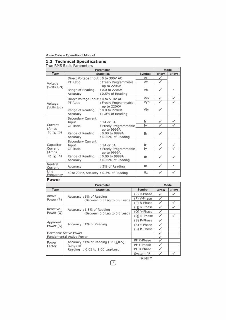
1.2 Technical SpecificationsTrue RMS Basic Parameters
Parameter ModeType Statistics Symbol 3P4W 3P3W
Voltage (Volts L-N)
Direct Voltage Input : 0 to 300V AC
PT Ratio : Freely Programmable up to 220KV
Range of Reading : 0.0 to 220KV
Accuracy : 0.5% of Reading
Vr
VY
Vb -
Voltage (Volts L-L)
Direct Voltage Input : 0 to 510V ACPT Ratio : Freely Programmable
up to 220KV Range of Reading : 0.0 to 220KVAccuracy : 1.0% of Reading
Secondary Current Input : 1A or 5ACT Ratio : Freely Programmable
up to 9999ARange of Reading : 0.00 to 9999AAccuracy : 0.25% of Reading
VryVyb
Vbr -
Ir
Iy
Ib -
Current(Amps Ir, Iy, Ib)
IrIy
Ib
Capacitor Current(Amps Ir, Iy, Ib)
Secondary Current Input : 1A or 5ACT Ratio : Freely Programmable
up to 9999ARange of Reading : 0.00 to 9999AAccuracy : 0.25% of Reading
Neutral Current
LineFrequency
Accuracy : 3% of Reading In -
Hz40 to 70 Hz, Accuracy : 0.3% of Reading
Power
Active Power (P)
Accuracy :1% of Reading(Between 0.5 Lag to 0.8 Lead)
(P) R-Phase
(P) Y-Phase
(P) B-Phase
Reactive Power (Q)
Accuracy :1.5% of Reading(Between 0.5 Lag to 0.8 Lead)
(Q) R-Phase
(Q) Y-Phase
(Q) B-Phase
Apparent Power (S)
Accuracy :1% of Reading
(S) R-Phase
(S) Y-Phase
(S) B-Phase
Harmonic Active PowerFundamental Active Power
Power Factor
Accuracy :1% of Reading (IPFI>0.5)Range ofReading : 0.05 to 1.00 Lag/Lead
PF R-Phase
PF Y-Phase
PF B-Phase
System PF
3
PowerCube – Operational Manual
TRINITY
Parameter Mode
Type Statistics 3P4W 3P3W
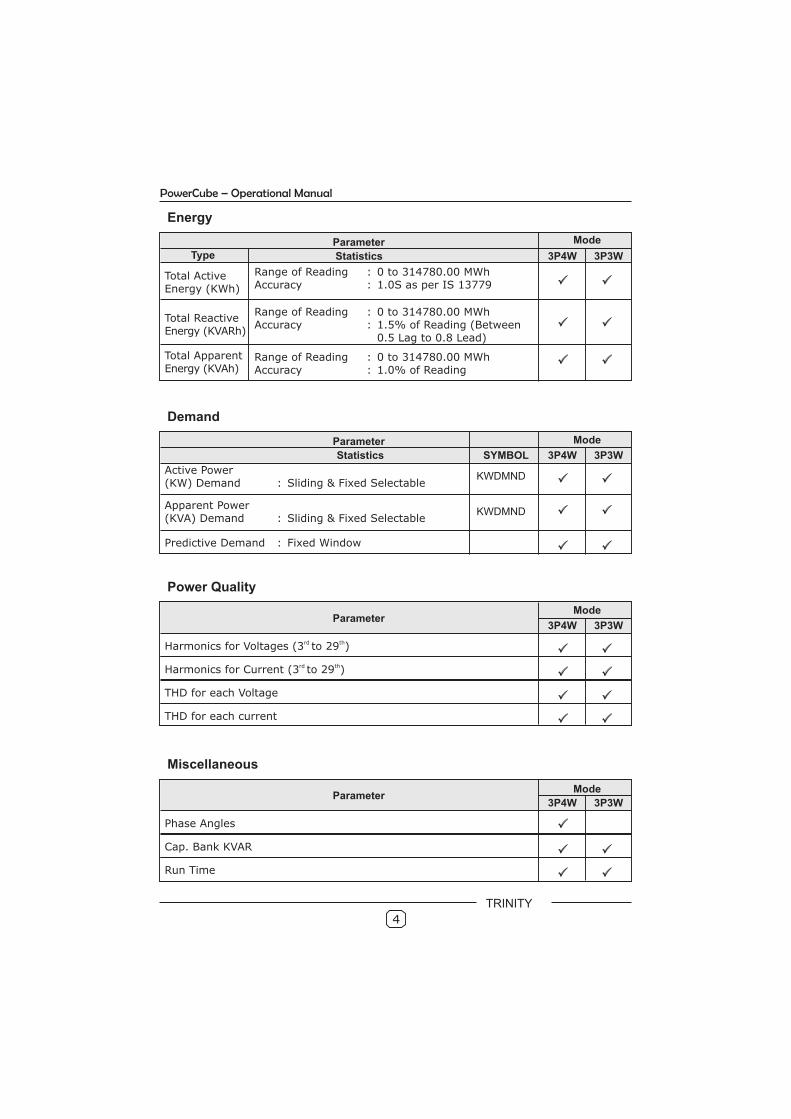
Total ActiveEnergy (KWh)
Range of Reading : 0 to 314780.00 MWhAccuracy : 1.0S as per IS 13779
Total ReactiveEnergy (KVARh)
Range of Reading : 0 to 314780.00 MWhAccuracy : 1.5% of Reading (Between
0.5 Lag to 0.8 Lead)
Total ApparentEnergy (KVAh)
Range of Reading : 0 to 314780.00 MWhAccuracy : 1.0% of Reading
Energy
Parameter Mode
Statistics 3P4W 3P3W
Active Power(KW) Demand : Sliding & Fixed Selectable
Apparent Power(KVA) Demand : Sliding & Fixed Selectable
Predictive Demand : Fixed Window
Demand
SYMBOL
KWDMND
KWDMND
ParameterMode
3P4W 3P3W
rd thHarmonics for Voltages (3 to 29 )
Power Quality
rd thHarmonics for Current (3 to 29 )
THD for each Voltage
THD for each current
ParameterMode
3P4W 3P3W
Phase Angles
Miscellaneous
Cap. Bank KVAR
Run Time
4
PowerCube – Operational Manual
TRINITY

1.2.1 Input Specifications
Supply : Three Phases and Neutral of a 3P4W
system/ three phases of a 3P3W system
Voltage
Direct Voltage Input : Up to 510V L-L and 300V L-N
PT Ratio : Freely Programmable up to 220KV
Site selectable.
Range of Reading : 1-220KV
Burden : 0.5VA
Current
Secondary Current
Input : 5A or 1A
Range of Reading : 0 – 9999A
Burden : < 1.0VA
Overload : 5A CT = 6A RMS Continuous
1A CT = 5A RMS Continuous
Power Supply:
Not needed as unit has in-built 3 phase supply with an operating range of
60 VAC - 480 VAC, 50-60 Hz.
An auxiliary supply is also provided for off site use of the Saturn. It also
operates on 60-480 VAC and 50-60 Hz.
1.2.3 Output Specifications
Programmable Relay Output
Relay outputs : 12.
Relay rating : 3A @ 250 VAC, Resistive load.
5
PowerCube – Operational Manual
TRINITY
2.0 Installation and commissioning
The PowerCube supports two installation modes – 3P4W and 3P3W. Theinstallation process of these modes is described below:
2.1 3P4W mode installation
Follow these steps to install & commission the unit:
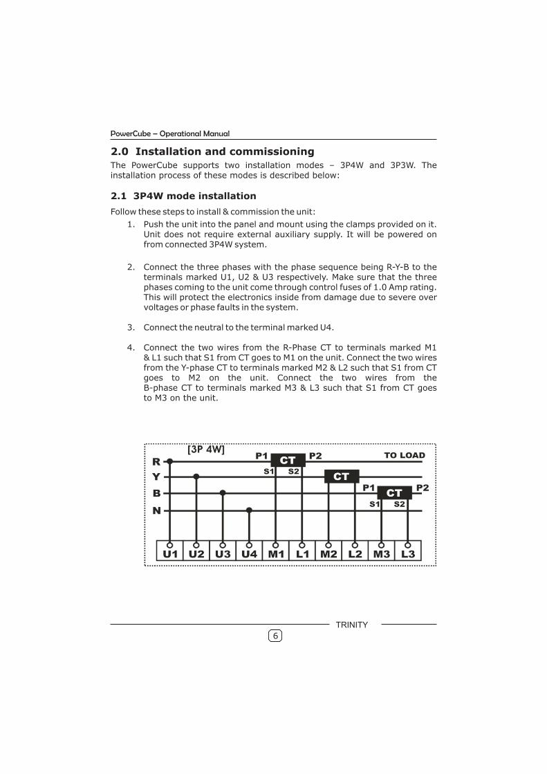
1. Push the unit into the panel and mount using the clamps provided on it. Unit does not require external auxiliary supply. It will be powered on from connected 3P4W system.
2. Connect the three phases with the phase sequence being R-Y-B to the terminals marked U1, U2 & U3 respectively. Make sure that the three phases coming to the unit come through control fuses of 1.0 Amp rating. This will protect the electronics inside from damage due to severe over voltages or phase faults in the system.
3. Connect the neutral to the terminal marked U4.
4. Connect the two wires from the R-Phase CT to terminals marked M1& L1 such that S1 from CT goes to M1 on the unit. Connect the two wires from the Y-phase CT to terminals marked M2 & L2 such that S1 from CT goes to M2 on the unit. Connect the two wires from the B-phase CT to terminals marked M3 & L3 such that S1 from CT goesto M3 on the unit.
6
PowerCube – Operational Manual
TRINITY
5. Connect the two wires from the R-Phase capacitor bank CT to terminals marked CM1 & CL1 such that S1 from CT goes to CM1 on the unit. Connect the two wires from the Y-phase capacitor bank CT to terminals marked CM2 & CL2 such that S1 from CT goes to CM2 on the unit. Connect the two wires from the B-phase capacitor bank CT to terminals marked CM3 & CL3 such that S1 from CT goes to CM3 on the unit.
6. Switch on the three phases supply. Unit will power on from these three phases supply and display company information for 4 to 5 seconds.
7. After that, it will display the first page.
8. If there is very little current in the CT circuits, the unit may show PF as 0.999 or 1.000. This will go away as soon as the current builds up in the CURRENT TRANSFORMERS (CTs) above 0.4 % of rated CT.
9. The unit needs to be programmed for the various parameters which are field programmable, and for selecting the various options supported. See OPERATIONAL DETAILS chapter for doing this.
10.The unit is ready for operation.
2.2 PowerCube in 3P3W mode installation
Follow these steps to install & commission the unit:
1. Push the unit into the panel and mount using the clamps provided. Unit does not required external auxiliary supply. It will be powered on from connected 3P3W system.
2. Connect the three phases with the R phase going to the terminal U1, B phase going to terminal U3 and Y phase going to terminal U4. Make sure that the three phases coming to the unit come through control fuses of 1.0 Amp rating. This will protect the electronics inside from damage due to severe over voltages or phase faults in the system.
3. Connect the two wires from the R-Phase CT to terminals marked M1 & L1 such that S1 from CT goes to M1 on the unit. Connect the two wires from the B-phase CT to terminals marked M3 & L3 such that S1 from CT goes to M3 on the unit.
7
Implement Step-5 if relays are used for PF-Controlling action
PowerCube – Operational Manual
TRINITY
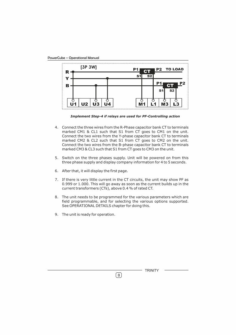
4. Connect the three wires from the R-Phase capacitor bank CT to terminals marked CM1 & CL1 such that S1 from CT goes to CM1 on the unit. Connect the two wires from the Y-phase capacitor bank CT to terminals marked CM2 & CL2 such that S1 from CT goes to CM2 on the unit. Connect the two wires from the B-phase capacitor bank CT to terminals marked CM3 & CL3 such that S1 from CT goes to CM3 on the unit.
5. Switch on the three phases supply. Unit will be powered on from this three phase supply and display company information for 4 to 5 seconds.
6. After that, it will display the first page.
7. If there is very little current in the CT circuits, the unit may show PF as 0.999 or 1.000. This will go away as soon as the current builds up in the current transformers (CTs), above 0.4 % of rated CT.
8. The unit needs to be programmed for the various parameters which are field programmable, and for selecting the various options supported. See OPERATIONAL DETAILS chapter for doing this.
9. The unit is ready for operation.
8
Implement Step-4 if relays are used for PF-Controlling action
PowerCube – Operational Manual
TRINITY
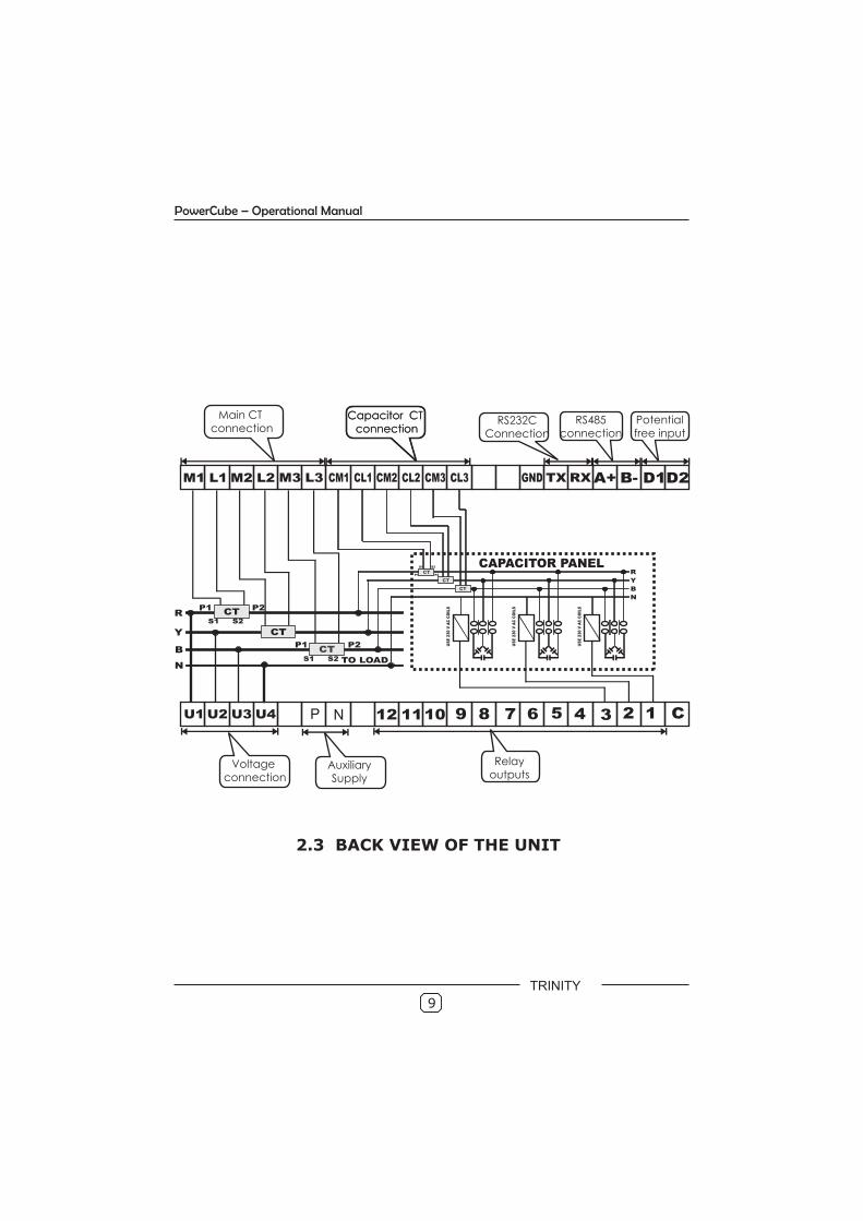
2.3 BACK VIEW OF THE UNIT
9
Main CT connection
Capacitor CT connection
Capacitor CT connection
RS232CConnection
RS485connection
Potential free input
Relayoutputs
Voltage connection
AuxiliarySupply
P N
PowerCube – Operational Manual
TRINITY
10
PowerCube – Operational Manual
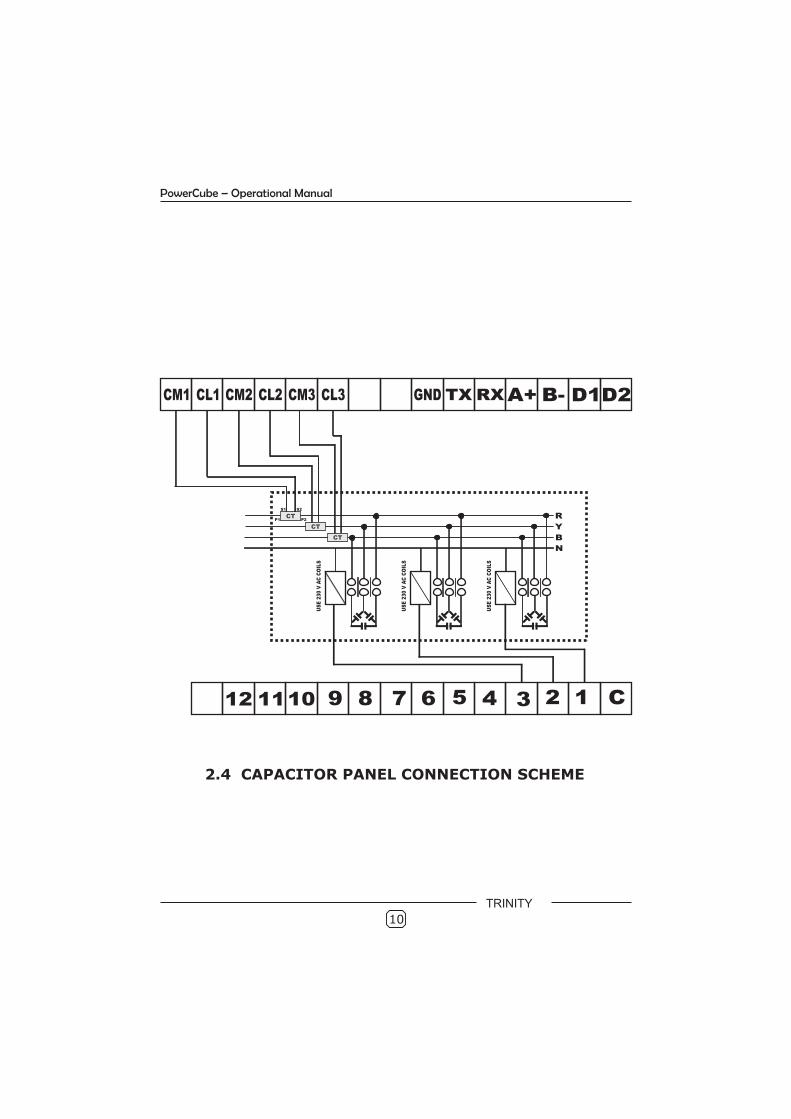
2.4 CAPACITOR PANEL CONNECTION SCHEME
TRINITY
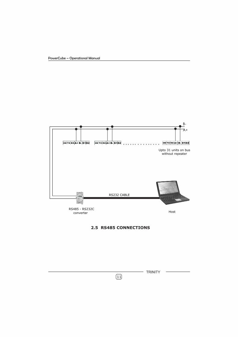
2.5 RS485 CONNECTIONS
RS232 CABLE
B -
Host
RS485 - RS232C
converter
Upto 31 units on bus without repeater
A +
11
PowerCube – Operational Manual
TRINITY
12
3.0 Operational Details
The PowerCube is a versatile meter, with all the necessary features to implement a robust electrical load management system. It can be configured to suit most control and communication needs. This is achieved by making as many parameters field programmable as possible.
There are basically two modes of operation in PowerCube:
1. Programming Mode2. Run Mode
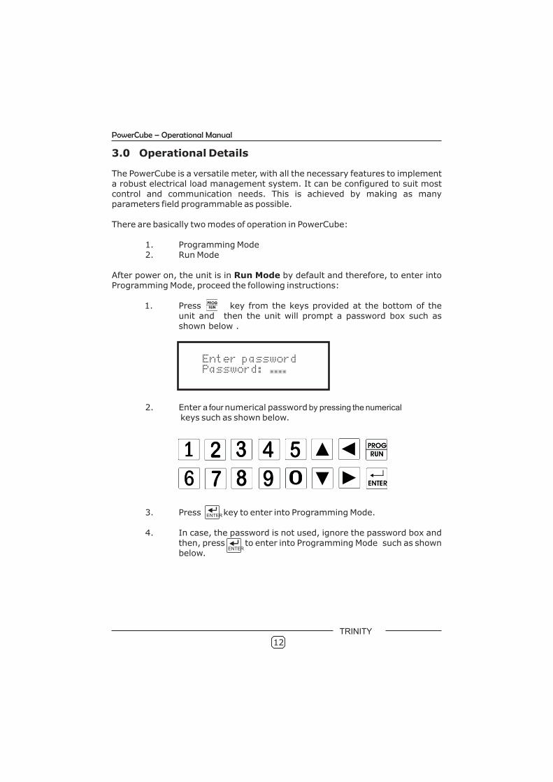
After power on, the unit is in Run Mode by default and therefore, to enter into Programming Mode, proceed the following instructions:
1. Press key from the keys provided at the bottom of theunit and then the unit will prompt a password box such asshown below .
2. Enter a four numerical password by pressing the numerical keys such as shown below.
3. Press key to enter into Programming Mode.
4. In case, the password is not used, ignore the password box and then, press to enter into Programming Mode such as shown below.
Enter passwordPassword: ****
ENTER
ENTER
PowerCube – Operational Manual
TRINITY
13
PowerCube – Operational Manual
1 3P4W
PT-Primary2 000240
3 PT-Secondary 110
4 MAINS - CT Primary 0245
5 MAINS-CT Secondary 5
6 CAPS - CT Primary 0500
7 CAPS-CT Secondary 5
Installation
No. Settable Parameters Values
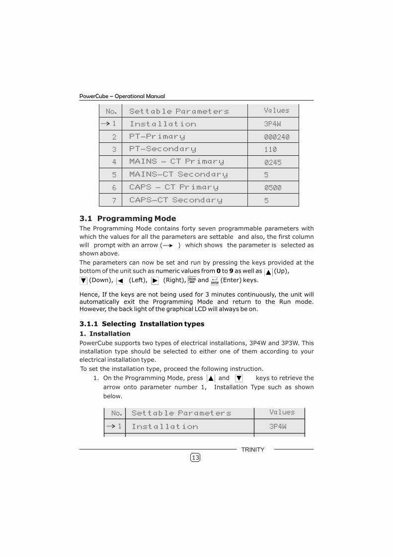
3.1 Programming Mode
The Programming Mode contains forty seven programmable parameters with
which the values for all the parameters are settable and also, the first column
will prompt with an arrow ( ) which shows the parameter is selected as
shown above.
The parameters can now be set and run by pressing the keys provided at the
bottom of the unit such as
1. Installation
PowerCube supports two types of electrical installations, 3P4W and 3P3W. This
installation type should be selected to either one of them according to your
electrical installation type.
To set the installation type, proceed the following instruction.
1. On the Programming Mode, press and keys to retrieve the
arrow onto parameter number 1, Installation Type such as shown
below.
numeric values from 0 to 9 as well as (Up),
(Down), (Left), (Right), and (Enter) keys.
Hence, If the keys are not being used for 3 minutes continuously, the unit will automatically exit the Programming Mode and return to the Run mode. However, the back light of the graphical LCD will always be on.
3.1.1 Selecting Installation types
1 3P4WInstallation
No. Settable Parameters Values
TRINITY

14
2. Press key. Simultaneously, both the arrow and the parameter value start blinking which shows that the parameter can now be set.
3. Set the Installation type by pressing and keys and then, press key to confirm the value. 4. If the setting is completed, press key to exit the Programming Mode and return to the Run Mode. 5. Or else, press key to proceed for the next programmable parameter.
3.1.2 Setting the PT Primary and PT secondary
2. PT-Primary & 3. PT-Secondary
Both the PT primary and PT secondary should be set to give for the actual voltage of PT operated meters. The PT-primary is freely programmable from 110V to 220000V and the PT Secondary is selectable from any one of the following voltages: 110V, 240V or 415V.
To set PT Primary and Secondary, proceed the following instructions.
1. On the Programming Mode, press and keys to retrieve the arrow onto parameter number 2, PT Primary such as shown below.
No. Settable Parameters Values
PT-Primary2 000240
3 PT-Secondary 110
2. Press key. Simultaneously, both the arrow and the parameter value start blinking which shows that the parameter can
now be set. 3. Set the PT Primary by pressing and keys until the desired value is received and then, press key to confirm the value. 4. Press key to retrieve the arrow onto parameter number 3, PT Secondary such as shown above. 5. Set the PT Secondary such as above step 2 and 3. 6. If the setting is completed, press key to exit the Programming Mode and return to the Run Mode. 7. Or else, press key to proceed to the next programmable parameter.
3.1.3 Setting Main CT Primary and CT Secondary
4. Main CT Primary & 5. Main CT Secondary Both the Main CT primary and CT secondary should be set to get actual current of
PowerCube – Operational Manual
TRINITY
PowerCube – Operational Manual
CT operated meters. The CT-primary is freely programmable from 110V to 220000V and the PT Secondary is selectable from any one of the following voltages: 110V, 240V or 415V.
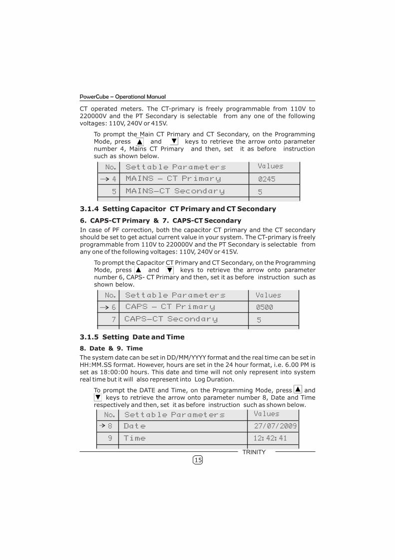
To prompt the Main CT Primary and CT Secondary, on the Programming Mode, press and keys to retrieve the arrow onto parameter number 4, Mains CT Primary and then, set it as before instruction such as shown below.
No. Settable Parameters Values
4 MAINS - CT Primary 0245
5 MAINS-CT Secondary 5
3.1.4 Setting Capacitor CT Primary and CT Secondary
6. CAPS-CT Primary & 7. CAPS-CT Secondary
In case of PF correction, both the capacitor CT primary and the CT secondary should be set to get actual current value in your system. The CT-primary is freely programmable from 110V to 220000V and the PT Secondary is selectable from any one of the following voltages: 110V, 240V or 415V.
To prompt the Capacitor CT Primary and CT Secondary, on the Programming Mode, press and keys to retrieve the arrow onto parameter number 6, CAPS- CT Primary and then, set it as before instruction such asshown below.
3.1.5 Setting Date and Time
8. Date & 9. Time
The system date can be set in DD/MM/YYYY format and the real time can be set in HH:MM.SS format. However, hours are set in the 24 hour format, i.e. 6.00 PM is set as 18:00:00 hours. This date and time will not only represent into system real time but it will also represent into Log Duration.
To prompt the DATE and Time, on the Programming Mode, press and keys to retrieve the arrow onto parameter number 8, Date and Time respectively and then, set it as before instruction such as shown below.
No. Settable Parameters Values
6 CAPS - CT Primary 0500
7 CAPS-CT Secondary 5
No. Settable Parameters Values
Time 12:42:41 9
Date 8 27/07/2009
15
TRINITY
16
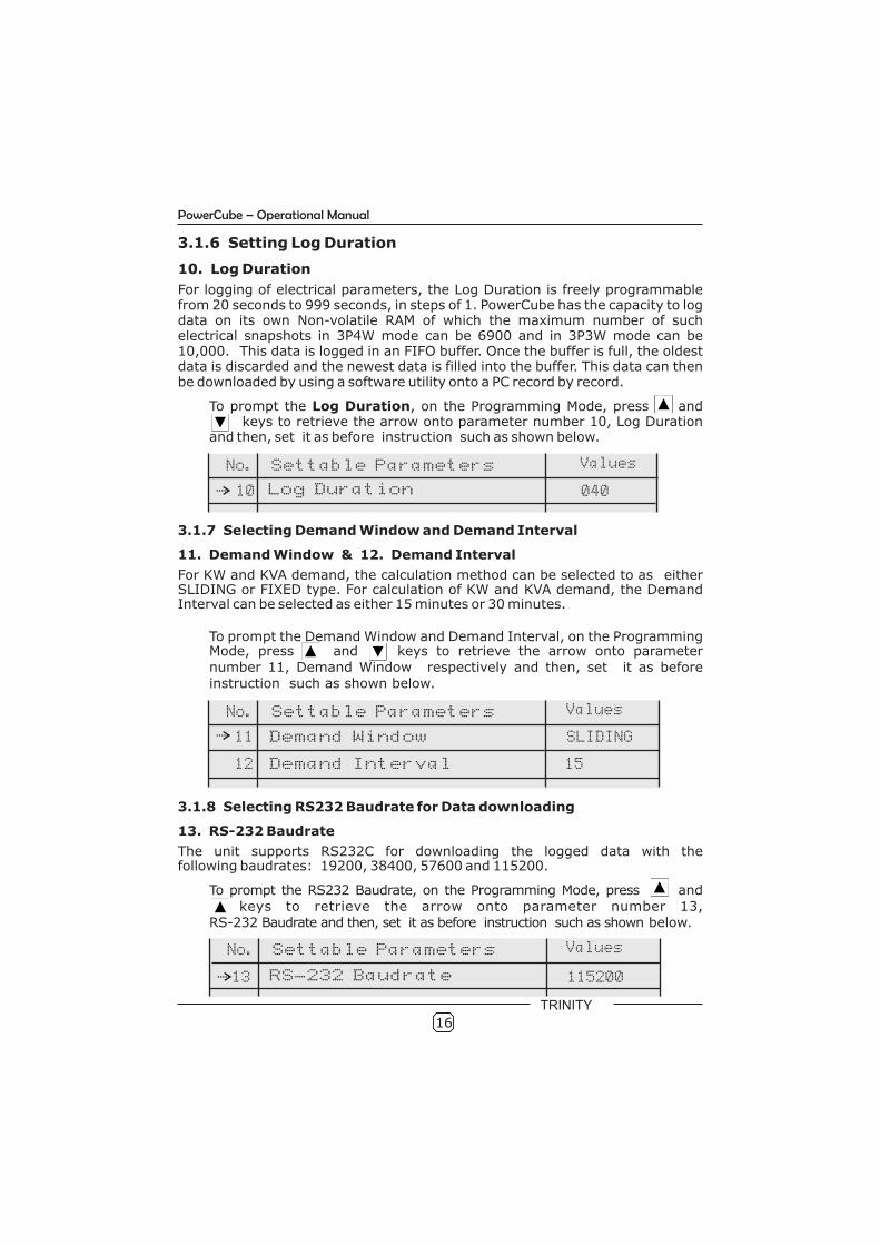
3.1.6 Setting Log Duration
10. Log Duration
For logging of electrical parameters, the Log Duration is freely programmable from 20 seconds to 999 seconds, in steps of 1. PowerCube has the capacity to log data on its own Non-volatile RAM of which the maximum number of such electrical snapshots in 3P4W mode can be 6900 and in 3P3W mode can be 10,000. This data is logged in an FIFO buffer. Once the buffer is full, the oldest data is discarded and the newest data is filled into the buffer. This data can then be downloaded by using a software utility onto a PC record by record.
To prompt the Log Duration, on the Programming Mode, press and keys to retrieve the arrow onto parameter number 10, Log Duration and then, set it as before instruction such as shown below.
3.1.7 Selecting Demand Window and Demand Interval
11. Demand Window & 12. Demand Interval
For KW and KVA demand, the calculation method can be selected to as either SLIDING or FIXED type. For calculation of KW and KVA demand, the Demand Interval can be selected as either 15 minutes or 30 minutes.
To prompt the Demand Window and Demand Interval, on the Programming Mode, press and keys to retrieve the arrow onto parameter number 11, Demand Window respectively and then, set it as beforeinstruction such as shown below.
3.1.8 Selecting RS232 Baudrate for Data downloading
13. RS-232 Baudrate
The unit supports RS232C for downloading the logged data with the following baudrates: 19200, 38400, 57600 and 115200.
To prompt the RS232 Baudrate, on the Programming Mode, press and keys to retrieve the arrow onto parameter number 13,RS-232 Baudrate and then, set it as before instruction such as shown below.
No. Settable Parameters Values
040 10 Log Duration
No. Settable Parameters Values
Demand Interval 15 12
Demand Window 11 SLIDING
No. Settable Parameters Values
115200 13 RS-232 Baudrate
PowerCube – Operational Manual
TRINITY
17
PowerCube – Operational Manual
3.1.9 Selecting a RS-485 Baudrate
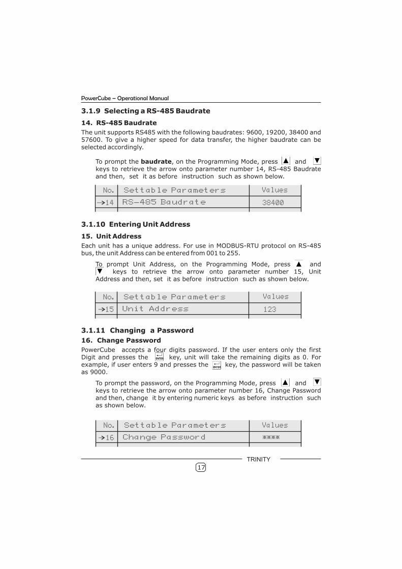
14. RS-485 Baudrate
The unit supports RS485 with the following baudrates: 9600, 19200, 38400 and 57600. To give a higher speed for data transfer, the higher baudrate can be selected accordingly.
To prompt the baudrate, on the Programming Mode, press and keys to retrieve the arrow onto parameter number 14, RS-485 Baudrate
and then, set it as before instruction such as shown below.
3.1.10 Entering Unit Address
15. Unit Address
Each unit has a unique address. For use in MODBUS-RTU protocol on RS-485 bus, the unit Address can be entered from 001 to 255.
To prompt Unit Address, on the Programming Mode, press and keys to retrieve the arrow onto parameter number 15, Unit Address and then, set it as before instruction such as shown below.
3.1.11 Changing a Password
16. Change Password
PowerCube accepts a four digits password. If the user enters only the first Digit and presses the key, unit will take the remaining digits as 0. For example, if user enters 9 and presses the key, the password will be takenas 9000.
To prompt the password, on the Programming Mode, press and keys to retrieve the arrow onto parameter number 16, Change Password and then, change it by entering numeric keys as before instruction suchas shown below.
No. Settable Parameters Values
38400 14 RS-485 Baudrate
No. Settable Parameters Values
123 15 Unit Address
No. Settable Parameters Values
**** 16 Change Password
TRINITY
18
3.1.12 Setting the Event Number, Event parameter, Event Value, EventSeconds and Event On.
The minimum and maximum threshold values to be logged according to your desired parameters can be described such as shown.
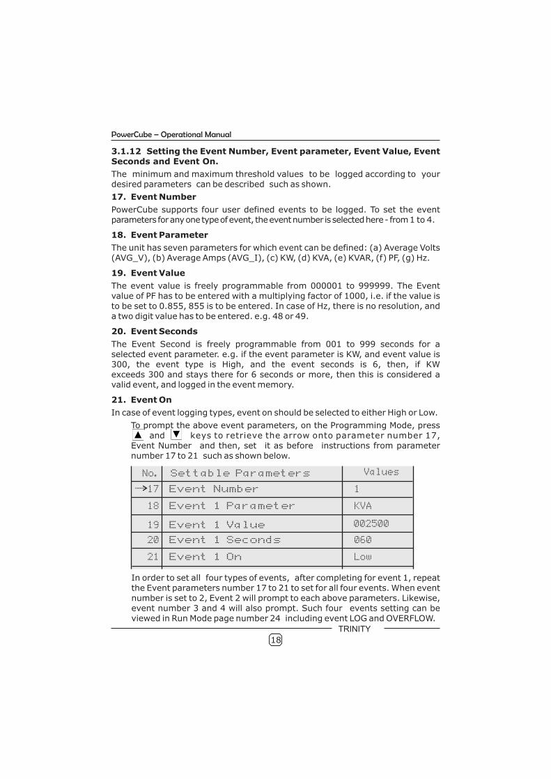
17. Event Number
PowerCube supports four user defined events to be logged. To set the event parameters for any one type of event, the event number is selected here - from 1 to 4.
18. Event Parameter
The unit has seven parameters for which event can be defined: (a) Average Volts (AVG_V), (b) Average Amps (AVG_I), (c) KW, (d) KVA, (e) KVAR, (f) PF, (g) Hz.
19. Event Value
The event value is freely programmable from 000001 to 999999. The Event value of PF has to be entered with a multiplying factor of 1000, i.e. if the value is to be set to 0.855, 855 is to be entered. In case of Hz, there is no resolution, and a two digit value has to be entered. e.g. 48 or 49.
20. Event Seconds
The Event Second is freely programmable from 001 to 999 seconds for a selected event parameter. e.g. if the event parameter is KW, and event value is 300, the event type is High, and the event seconds is 6, then, if KW exceeds 300 and stays there for 6 seconds or more, then this is considered a valid event, and logged in the event memory.
21. Event On
In case of event logging types, event on should be selected to either High or Low.
To prompt the above event parameters, on the Programming Mode, press and keys to retrieve the arrow onto parameter number 17,
Event Number and then, set it as before instructions from parameter number 17 to 21 such as shown below.
No. Settable Parameters Values
Event 1 Parameter
Event 1 On
KVA
Low
002500
18
21
Event Number
Event 1 Seconds
Event 1 Value
17
20
19
1
060
In order to set all four types of events, after completing for event 1, repeat the Event parameters number 17 to 21 to set for all four events. When event number is set to 2, Event 2 will prompt to each above parameters. Likewise, event number 3 and 4 will also prompt. Such four events setting can be viewed in Run Mode page number 24 including event LOG and OVERFLOW.
PowerCube – Operational Manual
TRINITY

19
PowerCube – Operational Manual
TRINITY
3.1.13 Setting the Relay, Control Stages, Control Action, On Delay, Off Delay, Switching Delay, Target PF and Second Target PF.
For PF correction application, the parameters which are compulsory to configure can be described such as.
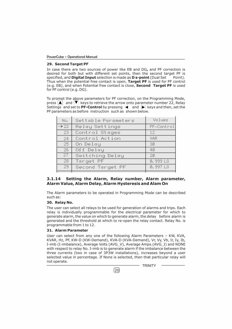
22. Relay Settings
PowerCube has twelve relay contacts which can be used for both alarm generation and PF-control or it can be used only for either Alarm or PF-control. If user selects Alarm mode, all twelve inbuilt relays work for Alarm action only. Consequently, the parameter numbers from 23 to 29 as well as 46, 47 and 48 will not be applicable. In case of PF-Control, if the Control Stage is set to twelve, all relays will work only for PF correction and parameter numbers 30 to 35 will not be applicable. If the Control Stage is set to eight, the eight relays will work for PF control and relays nine to twelve can be used for Alarm action.
23. Control Stages
For PF correction, the control stages can be specified to 4 or 8 or 10 or 12 as per the connected capacitor banks stages and then relays 6 to 12 or 9 to 12or 11 to 12 can be specified for Alarm action and is also reflected in Run ModePage No. 27. Hence the programmable parameter numbers 30 to 35 will beapplicable for alarm specification.
24. Control Action
This determines the control algorithm used for PF correction. User can select any one of the following algorithm types: FIFO, BINARY, VAR or PID.
25. On Delay
For relay connection, On Delay is freely programmable from 10 to 60 seconds. If the system PF is less than the target PF and PowerCube needs to switch ON relays, then On Delay is the time in seconds for which PowerCube checks whether this condition is persistent or not. If before On Delay seconds, target PF is achieved or overshot, then this On Delay timer resets to zero.
26. Off Delay
For relay disconnection, Off Delay is freely programmable from 10 to 60 seconds. If the system PF is more than the target PF and PowerCube needs to switch Off relays, then Off Delay is the time in seconds for which PowerCube checks whether this condition is persistent or not. If before Off Delay seconds, target PFis achieved, then this Off Delay timer resets to zero.
27. Switching Delay
Switching Delay is freely programmable from 10 to 60 seconds. After every switching of the relays for PF control (whether ON or OFF) PowerCube stops taking control action for Switching Delay number of seconds. This is one type of a digital dead band.
28. Target PF
Target PF can be entered from 0.800 LAG to 0.800 LEAD.
20
No. Settable Parameters
23
Relay Settings
Control Stages
Control Action
Switching Delay
22
24
27
Values
12
VAR
20
40 Off Delay
Target PF
On Delay
Second Target PF
25
28
26
29
PF-Control
30
0.999 LG
0.997 LG
3.1.14 Setting the Alarm, Relay number, Alarm parameter, Alarm Value, Alarm Delay, Alarm Hysteresis and Alam On
The Alarm parameters to be operated in Programming Mode can be described such as:
30. Relay No.
The user can select all relays to be used for generation of alarms and trips. Each relay is individually programmable for the electrical parameter for which to generate alarm, the value on which to generate alarm, the delay before alarm is generated and the threshold at which to re-open the relay contact. Relay No. is programmable from 1 to 12.
31. Alarm Parameter
User can select from any one of the following Alarm Parameters – KW, KVA, KVAR, Hz, PF, KW-D (KW-Demand), KVA-D (KVA-Demand), Vr, Vy, Vb, Ir, Iy, Ib, I-imb (I-imbalance), Average Volts (AVG_V), Average Amps.(AVG_I) and NONE with respect to relay No. I-imb is to generate alarm if the imbalance between the three currents (two in case of 3P3W installations), increases beyond a user selected value in percentage. If None is selected, then that particular relay will not operate.
PowerCube – Operational Manual
To prompt the above parameters for PF correction, on the Programming Mode, press and keys to retrieve the arrow onto parameter number 22, Relay Settings and set to PF-Control by pressing and keys and then, set the PF parameters as before instruction such as shown below.
TRINITY
29. Second Target PF
In case there are two sources of power like EB and DG, and PF correction is desired for both but with different set points, then the second target PF is specified, and Digital Input selection is made as D s-point (Dual Set Point). Thus when the potential free contact is open, Target PF is used for PF control (e.g. EB), and when Potential free contact is close, Second Target PF is used for PF control (e.g. DG).

No. Settable Parameters
31
Relay No
Alarm Parameter
Alarm Value
Alarm On
30
32
35
Values
KW
0220
LOW
10% Alarm Hysterisis
Alarm Delay 33
34
1
60
32. Alarm Value
For selected alarm parameters, Alarm Value is freely programmable from 1 to 9999. If the selected alarm parameter is I-imb, make sure the value entered here is between 1 and 99, because this value is taken in percentage form. If the selected alarm parameter is PF, then the alarm value will be from 01 to 99, with a multiplying factor of 0.01. If the selected alarm parameter is Hz, then the alarm value will be from 00.1 to 99.9.
33. Alarm Delay
In alarm mode, before the relay is switched on or off, the unit checks for alarm delay seconds whether the condition for on or off action is persistent or not, for Alarm Delay seconds. Alarm Delay is freely programmable from 2 to 99 seconds.
34. Alarm Hysterisis
The Alarm Hysterisis is programmable from 01% to 99% (in percentage form). It basically specifies the point at which the relay which has been switched on, to be switched off. e.g. If the alarm value is 1000 , and the hysterisis is 2% , then , the relay will switch on when the parameter exceeds 1000 and will switch off when it falls below 980.
35. Alarm On
For alarm type, Alarm On can be selected to HIGH or LOW. If alarm type is HIGH then alarm will be activated when system value is equal to or greater than the Alarm value. If alarm type is LOW then alarm will be activated when system value is less than Alarm value.
To prompt the above parameters for Alarm Action, on the Programming Mode, press and keys to retrieve the arrow onto parameter number 22, Relay Settings and set to Alarm by pressing and keys and then, set all the alarm parameters as before instruction such as shown below.
PowerCube – Operational Manual
21
TRINITY
3.1.15 Setting Back Light On Time
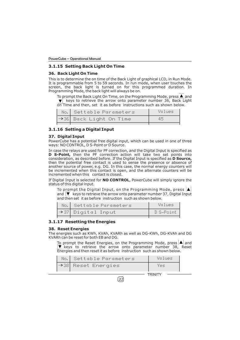
36. Back Light On Time
This is to determine the on time of the Back Light of graphical LCD, in Run Mode. It is programmable from 5 to 59 seconds. In run mode, when user touches the screen, the back light is turned on for this programmed duration. In Programming Mode, the back light will always be on.
To prompt the Back Light On Time, on the Programming Mode, press and keys to retrieve the arrow onto parameter number 36, Back Light on Time and then, set it as before instructions such as shown below.
3.1.16 Setting a Digital Input
37. Digital InputPowerCube has a potential free digital input, which can be used in one of three ways: NO CONTROL, D S-Point or D Source.
In case the relays are used for PF correction, and the Digital Input is specified as D S-Point, then the PF correction action will take two set points into consideration, as described before. If the Digital Input is specified as D Source, then the potential free contact is used to sense the presence or absence of another source of power, e.g. DG. In this case, the normal energy counters will be incremented when this contact is open, and the alternate counters will be incremented when this contact is closed.
If Digital Input is selected for NO CONTROL, PowerCube will simply ignore the status of this digital input.
To prompt the Digital Input, on the Programming Mode, pressand keys to retrieve the arrow onto parameter number 37, Digital Input and then set it as before instruction such as shown below.
3.1.17 Resetting the Energies
38. Reset Energies The energies such as KWh, KVAh, KVARh as well as DG-KWh, DG-KVAh and DG KVARh can be reset for both EB and DG.
To prompt the Reset Energies, on the Programming Mode, press and keys to retrieve the arrow onto parameter number 38, Reset Energies and then reset it as before instruction such as shown below.
No. Settable Parameters Values
Back Light On Time 36 45
No. Settable Parameters Values
Digital Input 37 D S-Point
No. Settable Parameters Values
Reset Energies 38 Yes
PowerCube – Operational Manual
22
TRINITY
No. Settable Parameters Values
Reset Demand 39 Yes
No. Settable Parameters Values
Reset Logs 40 Yes
No. Settable Parameters Values
Reset Run Time 41 Yes
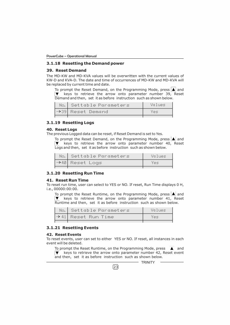
3.1.18 Resetting the Demand power
39. Reset Demand
The MD-KW and MD-KVA values will be overwritten with the current values of KW-D and KVA-D. The date and time of occurrences of MD-KW and MD-KVA will be replaced by current time and date.
To prompt the Reset Demand, on the Programming Mode, press and keys to retrieve the arrow onto parameter number 39, ResetDemand and then, set it as before instruction such as shown below.
3.1.19 Resetting Logs
40. Reset LogsThe previous Logged data can be reset, if Reset Demand is set to Yes.
To prompt the Reset Demand, on the Programming Mode, press and keys to retrieve the arrow onto parameter number 40, ResetLogs and then, set it as before instruction such as shown below.
3.1.20 Resetting Run Time
41. Reset Run TimeTo reset run time, user can select to YES or NO. If reset, Run Time displays 0 H, i.e., 00000:00:00.
To prompt the Reset Runtime, on the Programming Mode, press and keys to retrieve the arrow onto parameter number 41, Reset Runtime and then, set it as before instruction such as shown below.
3.1.21 Resetting Events
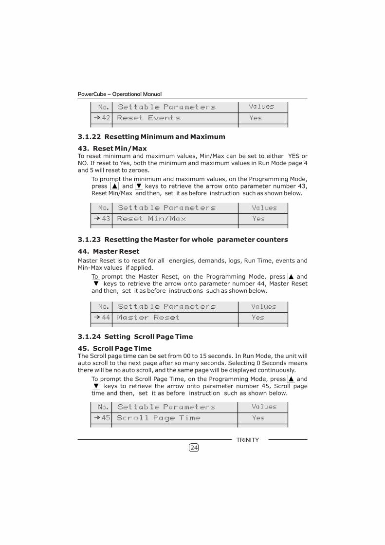
42. Reset EventsTo reset events, user can set to either YES or NO. If reset, all instances in each event will be deleted.
To prompt the Reset Runtime, on the Programming Mode, press and keys to retrieve the arrow onto parameter number 42, Reset event
and then, set it as before instruction such as shown below.
PowerCube – Operational Manual
23
TRINITY
No. Settable Parameters Values
Reset Events 42 Yes
No. Settable Parameters Values
Reset Min/Max 43 Yes
No. Settable Parameters Values
Master Reset 44 Yes
No. Settable Parameters Values
Scroll Page Time 45 Yes
3.1.22 Resetting Minimum and Maximum
43. Reset Min/MaxTo reset minimum and maximum values, Min/Max can be set to either YES or NO. If reset to Yes, both the minimum and maximum values in Run Mode page 4 and 5 will reset to zeroes.
To prompt the minimum and maximum values, on the Programming Mode, press and keys to retrieve the arrow onto parameter number 43, Reset Min/Max and then, set it as before instruction such as shown below.
3.1.23 Resetting the Master for whole parameter counters
44. Master Reset
Master Reset is to reset for all energies, demands, logs, Run Time, events and Min-Max values if applied.
To prompt the Master Reset, on the Programming Mode, press and keys to retrieve the arrow onto parameter number 44, Master Reset
and then, set it as before instructions such as shown below.
3.1.24 Setting Scroll Page Time
45. Scroll Page TimeThe Scroll page time can be set from 00 to 15 seconds. In Run Mode, the unit will auto scroll to the next page after so many seconds. Selecting 0 Seconds means there will be no auto scroll, and the same page will be displayed continuously.
To prompt the Scroll Page Time, on the Programming Mode, press and keys to retrieve the arrow onto parameter number 45, Scroll page
time and then, set it as before instruction such as shown below.
PowerCube – Operational Manual
24
TRINITY
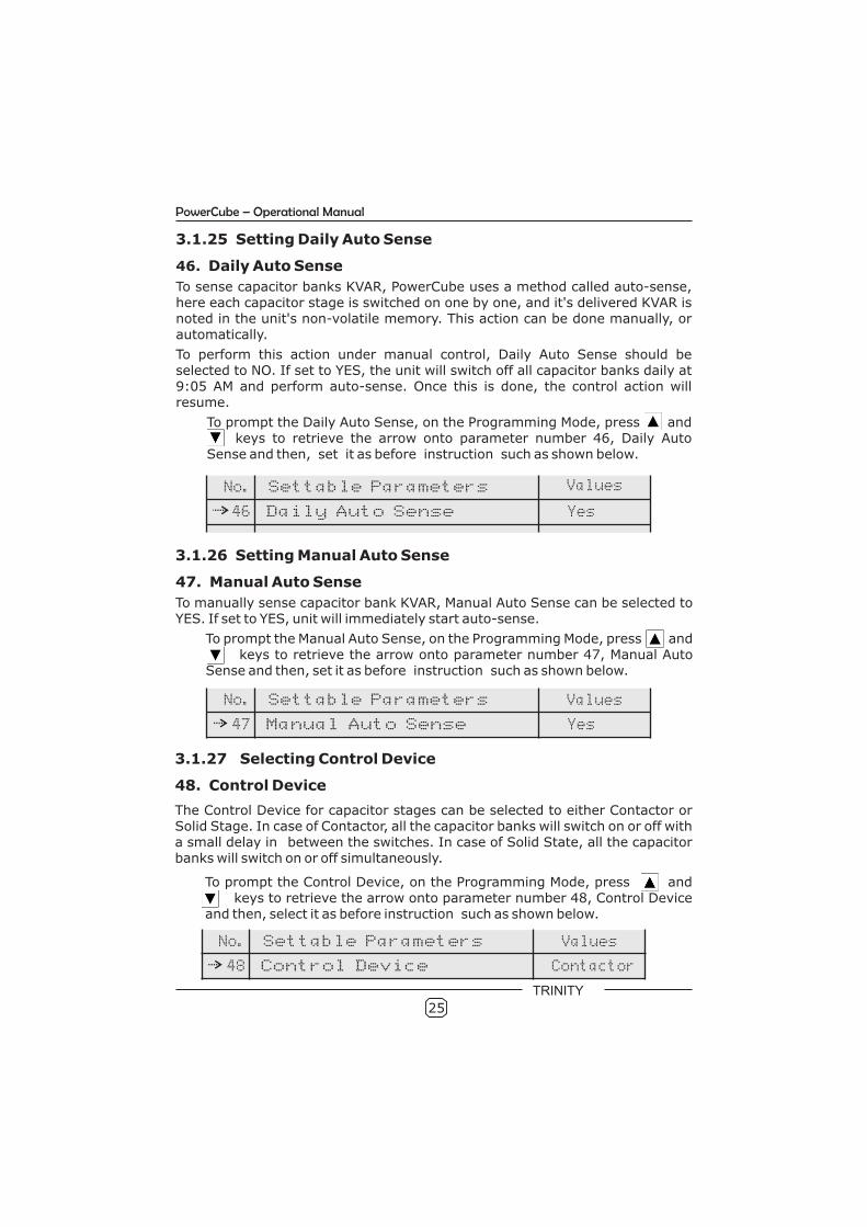
3.1.26 Setting Manual Auto Sense
47. Manual Auto Sense
To manually sense capacitor bank KVAR, Manual Auto Sense can be selected to YES. If set to YES, unit will immediately start auto-sense.
To prompt the Manual Auto Sense, on the Programming Mode, press and keys to retrieve the arrow onto parameter number 47, Manual Auto Sense and then, set it as before instruction such as shown below.
3.1.27 Selecting Control Device
48. Control Device
The Control Device for capacitor stages can be selected to either Contactor or Solid Stage. In case of Contactor, all the capacitor banks will switch on or off with a small delay in between the switches. In case of Solid State, all the capacitor banks will switch on or off simultaneously.
To prompt the Control Device, on the Programming Mode, press and keys to retrieve the arrow onto parameter number 48, Control Device and then, select it as before instruction such as shown below.
3.1.25 Setting Daily Auto Sense
46. Daily Auto Sense
To sense capacitor banks KVAR, PowerCube uses a method called auto-sense, here each capacitor stage is switched on one by one, and it's delivered KVAR is noted in the unit's non-volatile memory. This action can be done manually, or automatically.
To perform this action under manual control, Daily Auto Sense should be selected to NO. If set to YES, the unit will switch off all capacitor banks daily at 9:05 AM and perform auto-sense. Once this is done, the control action will resume.
To prompt the Daily Auto Sense, on the Programming Mode, press and keys to retrieve the arrow onto parameter number 46, Daily Auto
Sense and then, set it as before instruction such as shown below.
No. Settable Parameters Values
Daily Auto Sense 46 Yes
No.
No.
Settable Parameters
Settable Parameters
Manual Auto Sense
Control Device
47
48
Values
Values
Yes
Contactor
PowerCube – Operational Manual
25
TRINITY
3.2 Run mode
In the Run Mode, the various parameters measured and calculated by the meter are displayed on different pages; on a 240 X 128 back lit graphical LCD display.
All the power values displayed will autoscale from Kilo to Mega , once the value
crosses 10,000. e.g., if KWh ≥ 10000.0, it will show as 10.000 MWh immediately.
PowerCube plots voltage and current waveforms of R-Phase in RED color, Y-Phase in YELLOW color and B-Phase in BLUE color. Individual phase wise parameters are also color coded similarly.
Hence, top of each page shows the type of installation, date and time. Bottom of each page shows Run time in hhhhh:mm:ss format and page number with , , keys.
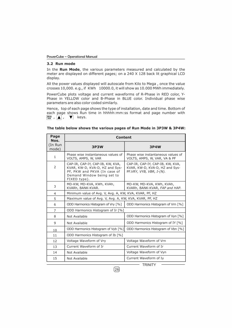
The table below shows the various pages of Run Mode in 3P3W & 3P4W:
Page Nos.
(In Run mode)
Content
3P3W 3P4W
1Phase wise instantaneous values ofVOLTS, AMPS, W, VAR
Phase wise instantaneous values ofVOLTS, AMPS, W, VAR, VA & PF
2CAP-IR, CAP-IY, CAP-IB, KW, KVA, KVAR, KW-D, KVA-D, HZ and Sys-PF, PKW and PKVA (In case of Demand Window being set to FIXED type).
CAP-IR, CAP-IY, CAP-IB, KW, KVA, KVAR, KW-D, KVA-D, HZ and Sys-PF.VRY, VYB, VBR, I-(N).
3MD-KW, MD-KVA, KWh, KVAh, KVARh, BANK-KVAR.
MD-KW, MD-KVA, KWh, KVAh, KVARh, BANK-KVAR, FAP and HAP.
4 Minimum value of Avg. V, Avg. A, KW, KVA, KVAR, PF, HZ
5 Maximum value of Avg. V, Avg. A, KW, KVA, KVAR, PF, HZ
6 ODD Harmonics Histogram of Vry [%] ODD Harmonics Histogram of Vrn [%]
7 ODD Harmonics Histogram of Ir [%]
8 Not Available ODD Harmonics Histogram of Vyn [%]
9 Not Available ODD Harmonics Histogram of IY [%]
10 ODD Harmonics Histogram of Vyb [%] ODD Harmonics Histogram of Vbn [%]
11 ODD Harmonics Histogram of Ib [%]
12 Voltage Waveform of Vry
13 Current Waveform of Ir
Voltage Waveform of Vrn
Current Waveform of Ir
15 Not Available
26
PowerCube – Operational Manual
14 Not Available Voltage Waveform of Vyn
Current Waveform of Iy
TRINITY
Page Nos.
(In Run mode)
Content
3P3W 3P4W
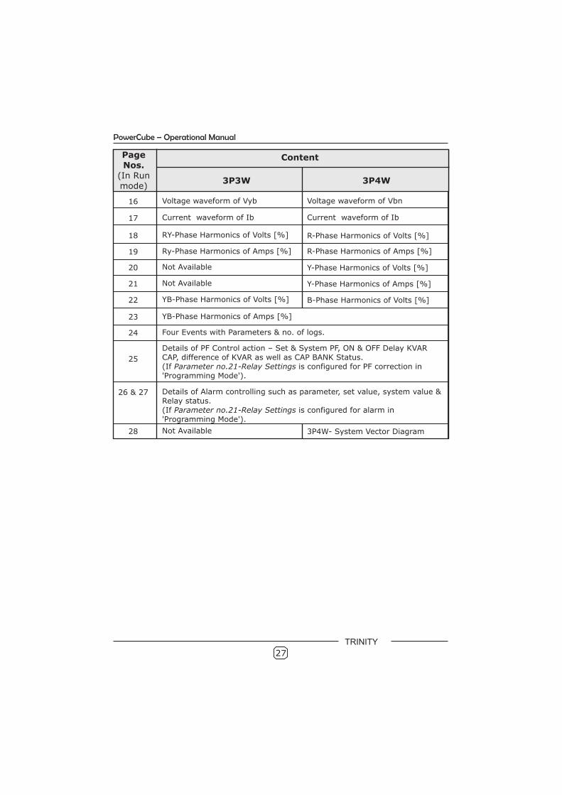
16 Voltage waveform of Vyb
17 Current waveform of Ib
18 RY-Phase Harmonics of Volts [%] R-Phase Harmonics of Volts [%]
19 Ry-Phase Harmonics of Amps [%]
20 Not Available Y-Phase Harmonics of Volts [%]
21 Not Available Y-Phase Harmonics of Amps [%]
22 YB-Phase Harmonics of Volts [%] B-Phase Harmonics of Volts [%]
23 YB-Phase Harmonics of Amps [%]
24 Four Events with Parameters & no. of logs.
25
Details of PF Control action – Set & System PF, ON & OFF Delay KVAR CAP, difference of KVAR as well as CAP BANK Status.(If Parameter no.21-Relay Settings is configured for PF correction in 'Programming Mode').
26 & 27 Details of Alarm controlling such as parameter, set value, system value & Relay status.(If Parameter no.21-Relay Settings is configured for alarm in 'Programming Mode').
28 Not Available 3P4W- System Vector Diagram
27
PowerCube – Operational Manual
Voltage waveform of Vbn
Current waveform of Ib
R-Phase Harmonics of Amps [%]
TRINITY
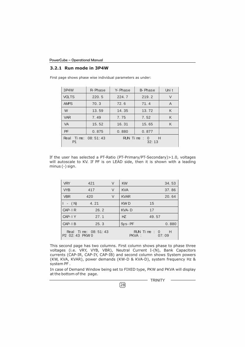
3.2.1 Run mode in 3P4W
First page shows phase wise individual parameters as under:
3P4W R-Phase Y-Phase B-Phase Unit
VOLTS 220.5 224.7 219.2 V
AMPS 70.3 72.6 71.4 A
W 13.59 14.35 13.72 K
VAR 7.49 7.75 7.52 K
VA 15.52 16.31 15.65 K
PF
Real Time: 08:51:43 RUN Time : 0 H P1 32:13
0.875 0.880 0.877
If the user has selected a PT-Ratio (PT-Primary/PT-Secondary)>1.0, voltages will autoscale to KV. If PF is on LEAD side, then it is shown with a leading minus (-) sign.
This second page has two columns. First column shows phase to phase three voltages (i.e. VRY, VYB, VBR), Neutral Current I-(N), Bank Capacitors currents (CAP-IR, CAP-IY, CAP-IB) and second column shows System powers (KW, KVA, KVAR), power demands (KW-D & KVA-D), system frequency Hz & system PF .
In case of Demand Window being set to FIXED type, PKW and PKVA will display at the bottom of the page.
28
PowerCube – Operational Manual
VRY 421 V
VYB 417 V
VBR 420 V
I - (N) 4.21
KW 34.53
KVA 37.86
KVAR 20.64
KW-D 15
KVA-D 17
HZ 49.57
Sys-PF 0.880
CAP-IR 26.2
CAP-IY 27.1
CAP-IB 25.3
Real Time: 08:51:43 P2 02:43 PKW:0
RUN Time : 0 H PKVA : 07:09
TRINITY
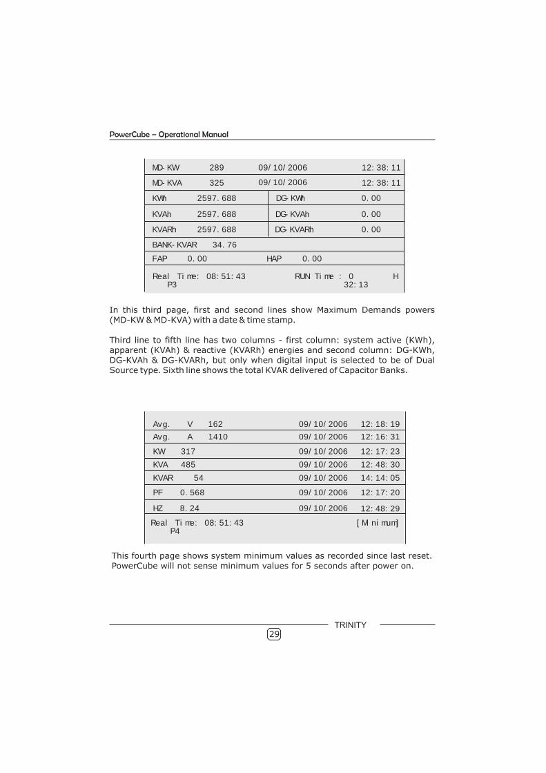
In this third page, first and second lines show Maximum Demands powers (MD-KW & MD-KVA) with a date & time stamp. Third line to fifth line has two columns - first column: system active (KWh), apparent (KVAh) & reactive (KVARh) energies and second column: DG-KWh, DG-KVAh & DG-KVARh, but only when digital input is selected to be of Dual Source type. Sixth line shows the total KVAR delivered of Capacitor Banks.
This fourth page shows system minimum values as recorded since last reset. PowerCube will not sense minimum values for 5 seconds after power on.
29
MD-KW 289 09/10/2006
MD-KVA 325
KWh 2597.688
KVAh 2597.688
12:38:11
12:38:11
DG-KWh 0.00
DG-KVAh 0.00
DG-KVARh 0.00
HAP 0.00
KVARh 2597.688
BANK-KVAR 34.76
FAP 0.00
09/10/2006
Real Time: 08:51:43 RUN Time : 0 H P3 32:13
Avg. V 162 09/10/2006 12:18:19
Avg. A 1410 09/10/2006 12:16:31
KW 317 09/10/2006 12:17:23
KVA 485 09/10/2006 12:48:30
KVAR 54 09/10/2006 14:14:05
PF 0.568 09/10/2006 12:17:20
HZ 8.24 09/10/2006 12:48:29
Real Time: 08:51:43 [Minimum] P4
PowerCube – Operational Manual
TRINITY
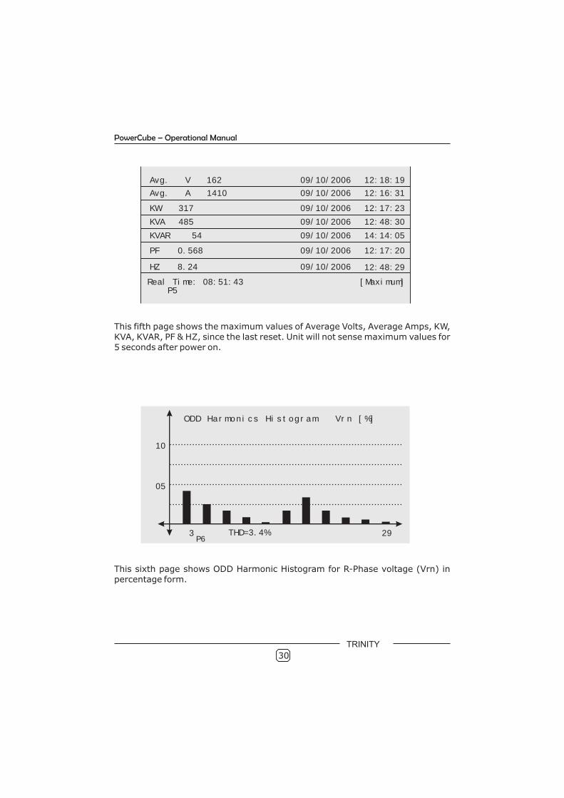
This fifth page shows the maximum values of Average Volts, Average Amps, KW, KVA, KVAR, PF & HZ, since the last reset. Unit will not sense maximum values for 5 seconds after power on.
This sixth page shows ODD Harmonic Histogram for R-Phase voltage (Vrn) in percentage form.
ODD Harmonics Histogram Vrn [%]
05
10
THD=3.4%3 29P6
30
Avg. V 162 09/10/2006 12:18:19
Avg. A 1410 09/10/2006 12:16:31
KW 317 09/10/2006 12:17:23
KVA 485 09/10/2006 12:48:30
KVAR 54 09/10/2006 14:14:05
PF 0.568 09/10/2006 12:17:20
HZ 8.24 09/10/2006 12:48:29
Real Time: 08:51:43 [Maximum] P5
PowerCube – Operational Manual
TRINITY
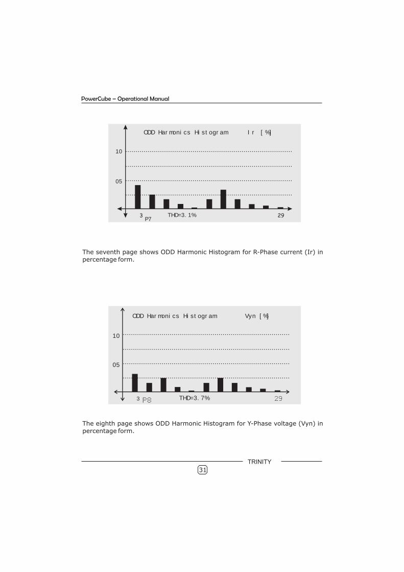
The seventh page shows ODD Harmonic Histogram for R-Phase current (Ir) in percentage form.
05
10
ODD Harmonics Histogram Vyn [%]
THD=3.7%3 29P8
The eighth page shows ODD Harmonic Histogram for Y-Phase voltage (Vyn) in percentage form.
31
05
10
Ir [%]
THD=3.1%3 29P7
ODD Harmonics Histogram
PowerCube – Operational Manual
TRINITY
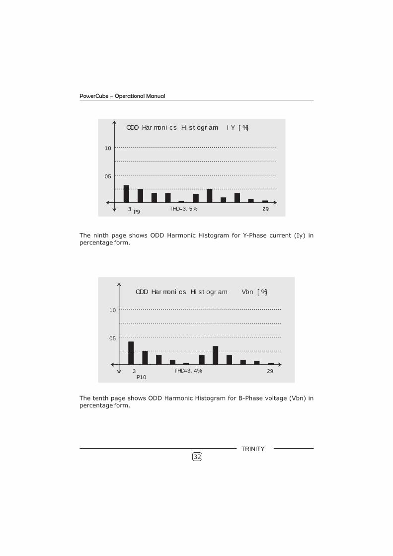
The ninth page shows ODD Harmonic Histogram for Y-Phase current (Iy) in percentage form.
The tenth page shows ODD Harmonic Histogram for B-Phase voltage (Vbn) in percentage form.
32
05
10
IY [%]
THD=3.5%3 29P9
ODD Harmonics Histogram
05
10
THD=3.4%3 29P10
ODD Harmonics Histogram Vbn [%]
PowerCube – Operational Manual
TRINITY
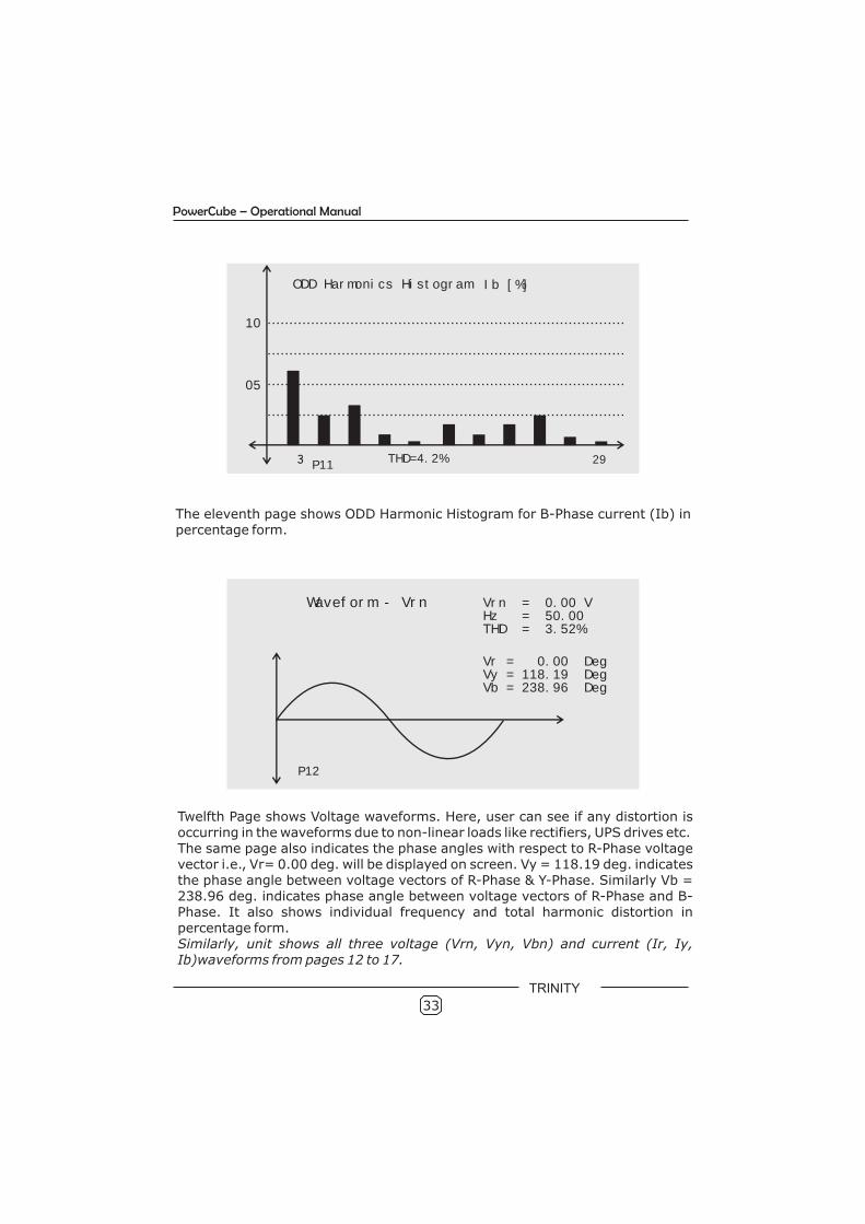
The eleventh page shows ODD Harmonic Histogram for B-Phase current (Ib) in percentage form.
Twelfth Page shows Voltage waveforms. Here, user can see if any distortion is occurring in the waveforms due to non-linear loads like rectifiers, UPS drives etc. The same page also indicates the phase angles with respect to R-Phase voltage vector i.e., Vr= 0.00 deg. will be displayed on screen. Vy = 118.19 deg. indicates the phase angle between voltage vectors of R-Phase & Y-Phase. Similarly Vb = 238.96 deg. indicates phase angle between voltage vectors of R-Phase and B-Phase. It also shows individual frequency and total harmonic distortion in percentage form. Similarly, unit shows all three voltage (Vrn, Vyn, Vbn) and current Ib)waveforms from pages 12 to 17.
(Ir, Iy,
33
05
10
Ib [%]
THD=4.2%3 29P11
ODD Harmonics Histogram
Waveform - Vrn Vrn = 0.00 VHz = 50.00THD = 3.52%
P12
Vr = 0.00 DegVy = 118.19 DegVb = 238.96 Deg
PowerCube – Operational Manual
TRINITY
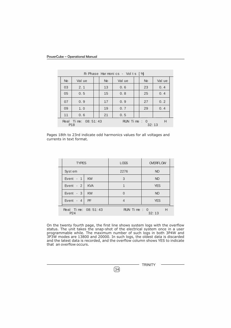
Pages 18th to 23rd indicate odd harmonics values for all voltages and currents in text format.
On the twenty fourth page, the first line shows system logs with the overflow status. The unit takes the snap-shot of the electrical system once in a user programmable while. The maximum number of such logs in both 3P4W and 3P3W modes are 13800 and 20000. In such logs, the oldest data is discarded and the latest data is recorded, and the overflow column shows YES to indicate that an overflow occurs.
34
R-Phase Harmonics - Volts [%]
No Value No Value No Value
03 2.1 13 0.6 23 0.4
05 0.5 15 0.8 25 0.4
07 0.9 17 0.9 27 0.2
09 1.0 19 0.7 29 0.4
11 0.6 21 0.5
Real Time: 08:51:43 RUN Time : 0 H P18 32:13
TYPES LOGS OVERFLOW
System 2276 NO
Event - 1 3 NO
Event - 2 1 YES
Event - 3 0 NO
Event - 4 4 YES
KW
KVA
KW
PF
Real Time: 08:51:43 RUN Time : 0 H P24 32:13
PowerCube – Operational Manual
TRINITY
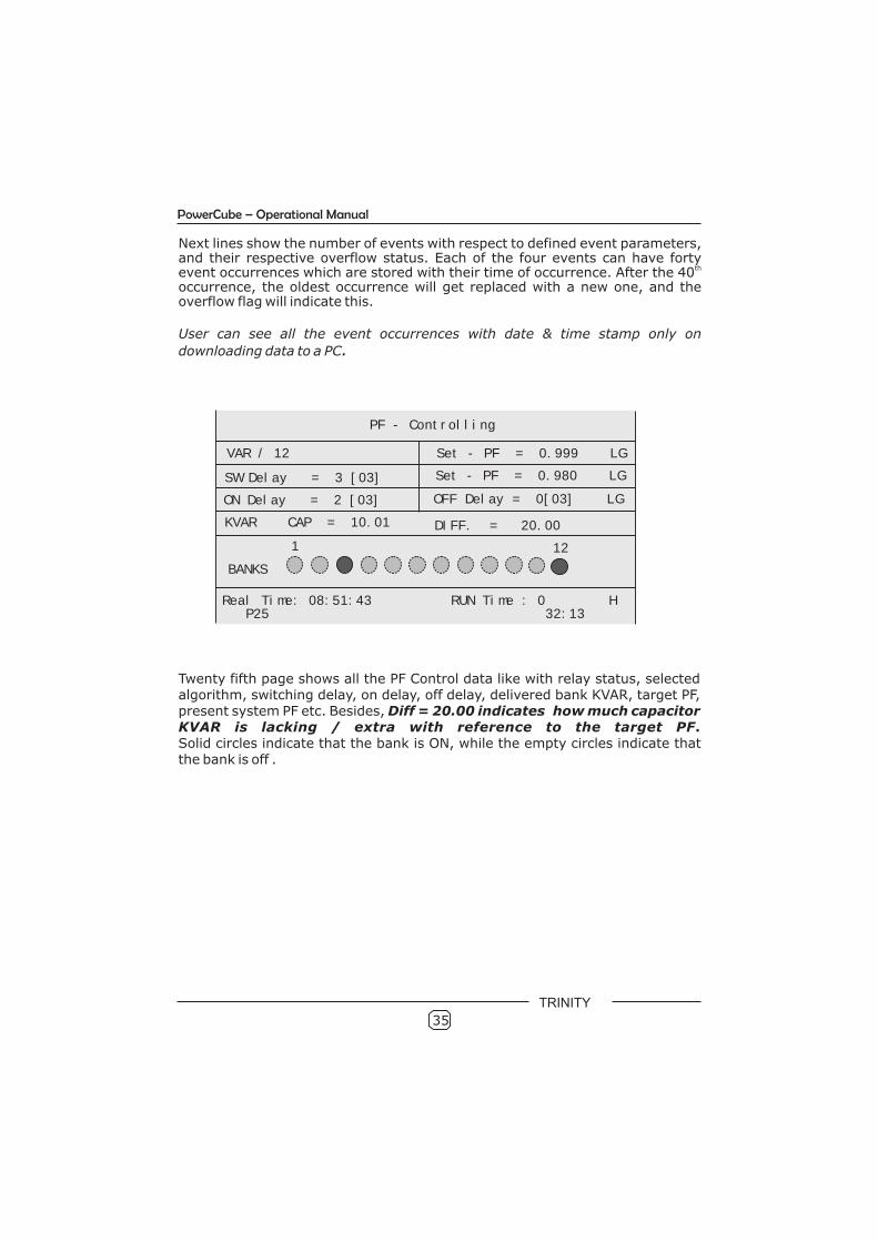
Twenty fifth page shows all the PF Control data like with relay status, selected algorithm, switching delay, on delay, off delay, delivered bank KVAR, target PF, present system PF etc. Besides, Diff = 20.00 indicates how much capacitor KVAR is lacking / extra with reference to the target PF. Solid circles indicate that the bank is ON, while the empty circles indicate that the bank is off .
Next lines show the number of events with respect to defined event parameters, and their respective overflow status. Each of the four events can have forty
thevent occurrences which are stored with their time of occurrence. After the 40 occurrence, the oldest occurrence will get replaced with a new one, and the overflow flag will indicate this.
User can see all the event occurrences with date & time stamp only on
downloading data to a PC.
35
PF - Controlling
VAR / 12
SW Delay = 3 [03]
ON Delay = 2 [03]
KVAR CAP = 10.01
Set - PF = 0.999 LG
Set - PF = 0.980 LG
OFF Delay = 0[03] LG
DIFF. = 20.00
BANKS
1 12
Real Time: 08:51:43 RUN Time : 0 H P25 32:13
PowerCube – Operational Manual
TRINITY
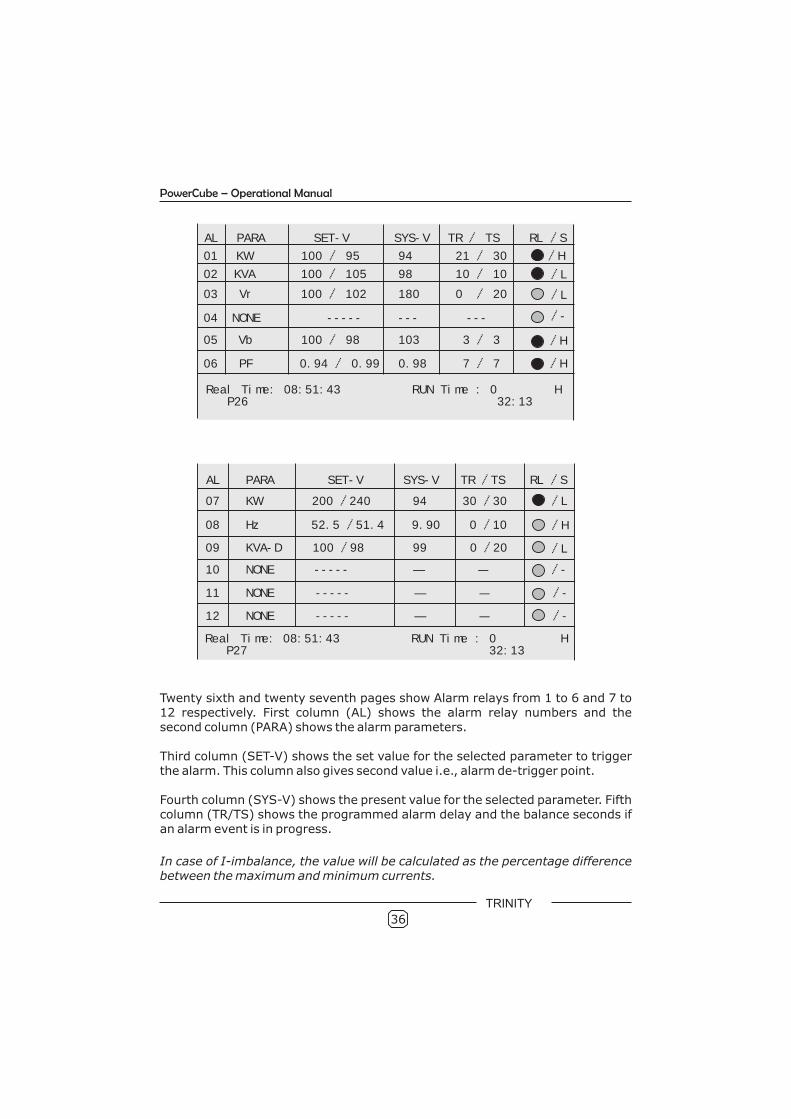
Twenty sixth and twenty seventh pages show Alarm relays from 1 to 6 and 7 to 12 respectively. First column (AL) shows the alarm relay numbers and the second column (PARA) shows the alarm parameters.
Third column (SET-V) shows the set value for the selected parameter to trigger the alarm. This column also gives second value i.e., alarm de-trigger point.
Fourth column (SYS-V) shows the present value for the selected parameter. Fifth column (TR/TS) shows the programmed alarm delay and the balance seconds if an alarm event is in progress.
In case of I-imbalance, the value will be calculated as the percentage difference between the maximum and minimum currents.
36
AL PARA SET-V SYS-V TR / TS RL /S
01 KW 100 / 95 94 21 / 30 /H
02 KVA 100 / 105 98 10 / 10
03 Vr 100 / 102 180 0 / 20
04 NONE -----
05 Vb 100 / 98 103 3 / 3
06 PF 0.94 / 0.99 0.98 7 / 7
/L
/L
/-
/H
/H
--- ---
Real Time: 08:51:43 RUN Time : 0 H P26 32:13
AL PARA SET-V SYS-V TR /TS RL /S
07 KW 200 /240 94 30 /30 /L
08 Hz 52.5 /51.4 9.90 0 /10
09 KVA-D 100 /98 99 0 /20
10
11
12
NONE
NONE
NONE
-----
-----
-----
—
—
—
—
—
—
/H
/L
/-
/-
/-
Real Time: 08:51:43 RUN Time : 0 H P27 32:13
PowerCube – Operational Manual
TRINITY
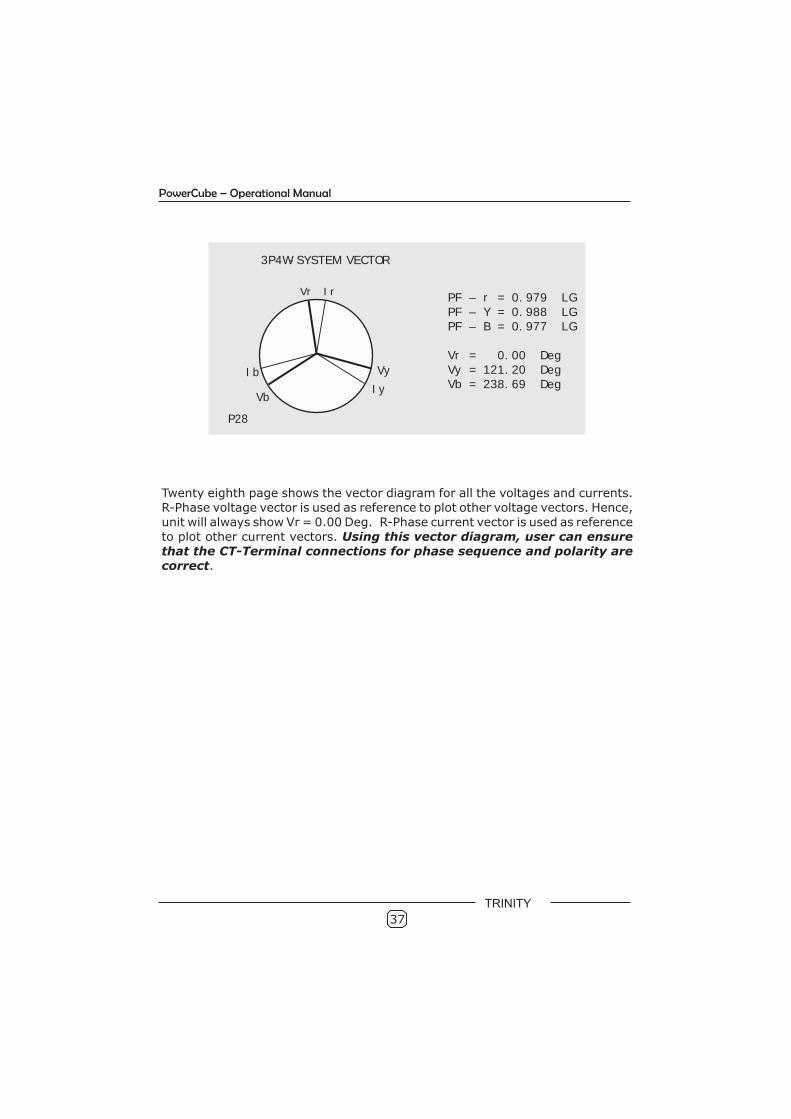
Twenty eighth page shows the vector diagram for all the voltages and currents. R-Phase voltage vector is used as reference to plot other voltage vectors. Hence, unit will always show Vr = 0.00 Deg. R-Phase current vector is used as reference to plot other current vectors. Using this vector diagram, user can ensure that the CT-Terminal connections for phase sequence and polarity are correct.
3P4W-SYSTEM VECTOR
PF – r = 0.979 LGPF – Y = 0.988 LGPF – B = 0.977 LG
Vr = 0.00 DegVy = 121.20 DegVb = 238.69 Deg
P28
Vb
Ir
Ib Vy
Iy
Vr
37
PowerCube – Operational Manual
TRINITY
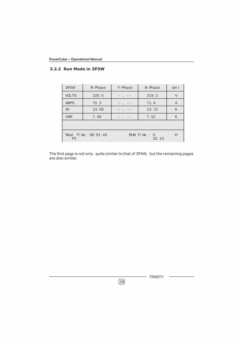
3.2.2 Run Mode in 3P3W
The first page is not only quite similar to that of 3P4W, but the remaining pages are also similar.
38
PowerCube – Operational Manual
3P3W R-Phase Y-Phase B-Phase Unit
VOLTS 220.5 - , -- 219.2 V
AMPS 70.3 - , -- 71.4 A
W 13.59 - , -- 13.72 K
VAR 7.49 - , -- 7.52 K
Real Time: 08:51:43 RUN Time : 0 H P1 32:13
TRINITY
4.0 Communication
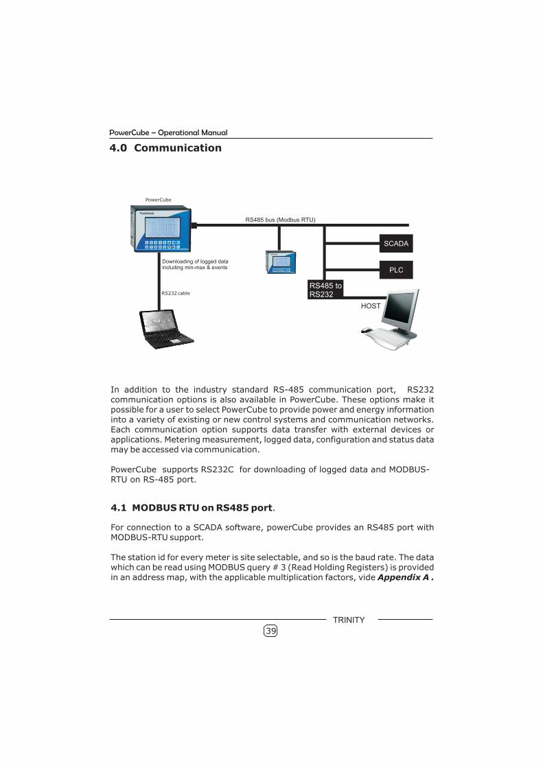
In addition to the industry standard RS-485 communication port, RS232 communication options is also available in PowerCube. These options make it possible for a user to select PowerCube to provide power and energy information into a variety of existing or new control systems and communication networks. Each communication option supports data transfer with external devices or applications. Metering measurement, logged data, configuration and status data may be accessed via communication.
PowerCube supports RS232C for downloading of logged data and MODBUS-RTU on RS-485 port.
4.1 MODBUS RTU on RS485 port.
For connection to a SCADA software, powerCube provides an RS485 port with MODBUS-RTU support.
The station id for every meter is site selectable, and so is the baud rate. The data which can be read using MODBUS query # 3 (Read Holding Registers) is provided in an address map, with the applicable multiplication factors, vide Appendix A .
39
RS232 cable
RS485 toRS232
PowerCube
PowerCube – Operational Manual
POWERCUBE
POWERCUBE
TRINITY

40
PowerCube – Operational Manual
4.2 Data Logging and RS232C
PowerCube has an 2 MB of non-volatile memory. This memory is used to store the minimum and maximum values of important parameters, user defined events and the snapshot of the entire electrical system where all instantaneous and integrated parameters along with Harmonic data are saved. Maximum number of such electrical snapshots in 3P4W mode can be 6900 and in 3P3W mode can be 10,000.
While the electrical snapshots as saved in the logs can give a good idea of the overall behavior of the system, the Event Log feature captures time-stamped records of important power system occurrences that can be aligned with corresponding production effects to better understand and optimize energy use and cost.
The log maintains a time-stamped record of 22 parameters in 3P3W and 33 parameters in 3P4W. One can monitor values over a day, a week, a month or any period to record the highest and lowest values of voltage, current, or power factor including Event parameters.
PowerCube supports RS232 for downloading logged data. Users are provided a CD for RS232 software installation along with the purchase of PowerCube.
TRINITY
TRINITY
41
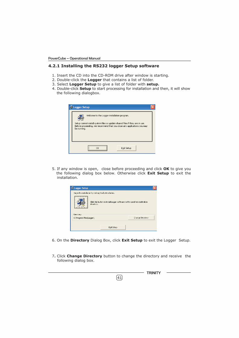
4.2.1 Installing the RS232 logger Setup software
1. Insert the CD into the CD-ROM drive after window is starting. 2. Double-click the Logger that contains a list of folder. 3. Select Logger Setup to give a list of folder with setup. 4. Double-click Setup to start processing for installation and then, it will show the following dialogbox.
5. If any window is open, close before proceeding and click OK to give you the following dialog box below. Otherwise click Exit Setup to exit the installation.
7. Click Change Directory button to change the directory and receive the following dialog box.
PowerCube – Operational Manual
6. On the Directory Dialog Box, click Exit Setup to exit the Logger Setup.
TRINITY
TRINITY
42
PowerCube – Operational Manual
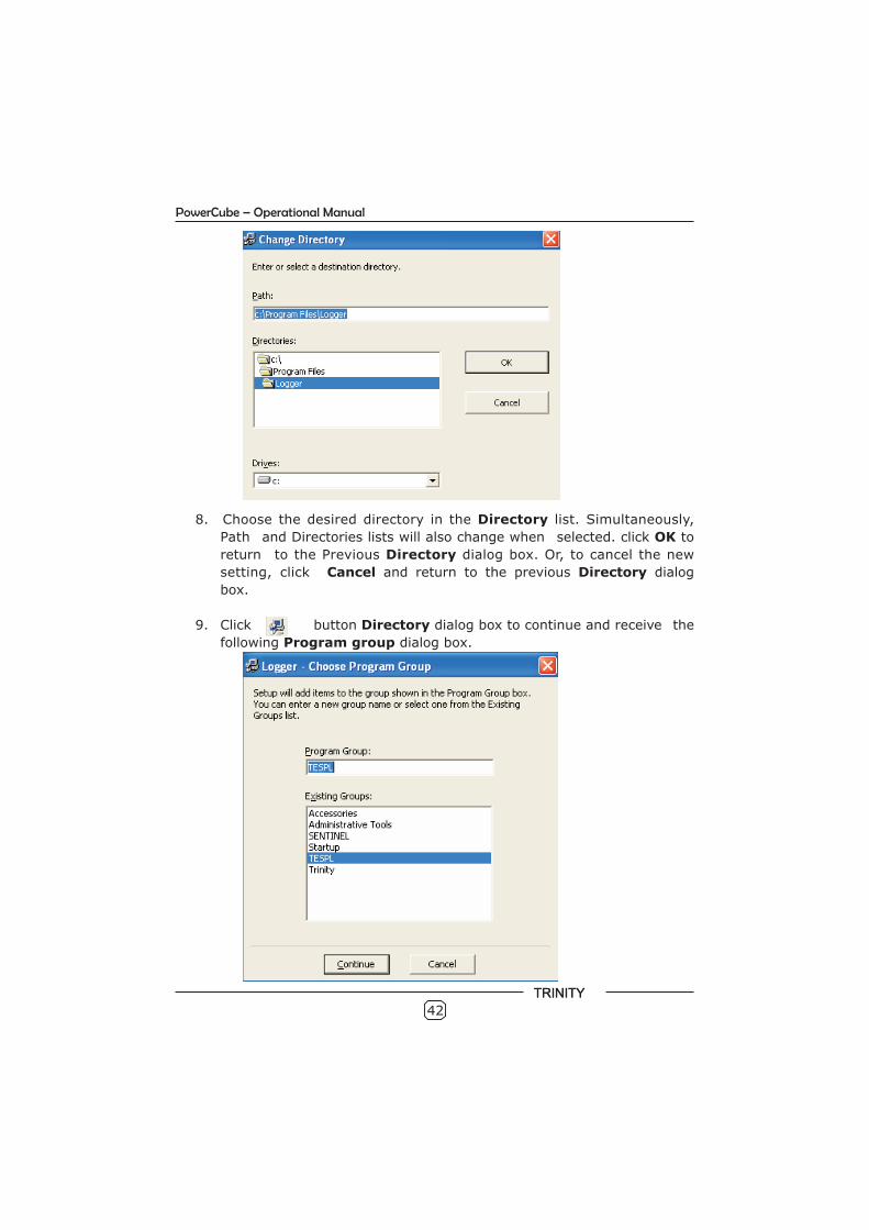
8. Choose the desired directory in the Directory list. Simultaneously,
Path and Directories lists will also change when selected. click OK to
return to the Previous Directory dialog box. Or, to cancel the new
setting, click Cancel and return to the previous Directory dialog
box.
9. Click button Directory dialog box to continue and receive the
following Program group dialog box.
TRINITY
43
Click Continue to continue and display a Version Conflict dialog box that asks you to keep your existed file. Click Yes to keep the existed file and except the new Version Numbers. It will give you second Version Conflict dialog box after changing the default version numbers.Click Yes to save change to the second version.
10.
11.
4.2.2 Logger Utility window
The Logger Utility contains information about the snapshot of the electrical system parameters such as the following.
Using the File menu: Configure com numbers and baud rate to download the logged data. Retrieve the logged data from the unit. Select KWh consumption for a particular date and time to EB and DG. Export odd harmonic graph into JPG format. Export Min/Max events, system data, harmonic data by using method 1 or method 2. Print setup for printing the exported data. Exit the Logger window.
Using the View menu: Min/Max event parameters with date and time events occurrence. Load system data for various parameters. Odd harmonics data for voltage and current with time and date.
Using the Graph menu: Color display graph for harmonics data analysis including THD. Color setting for odd harmonics voltage and currents.
After the installation is completed, find the Logger where the directory has been created. If the directory was created by default, find the Logger under theStart menu and start downloading the data.
In case, the installation is not accessible, user should install another folder in the Logger CD with the following instructions: Double click the Logger-Doubleclick Setup Exe-double click Logger Setup and then follow the instruction asbefore.
PowerCube – Operational Manual
Now a message will prompt such as the Logger Setup is completedsuccessfully. Click Ok to complete the Logger Setup.
TRINITY
44
PowerCube – Operational Manual
4.3 Handling the RS232 Logger
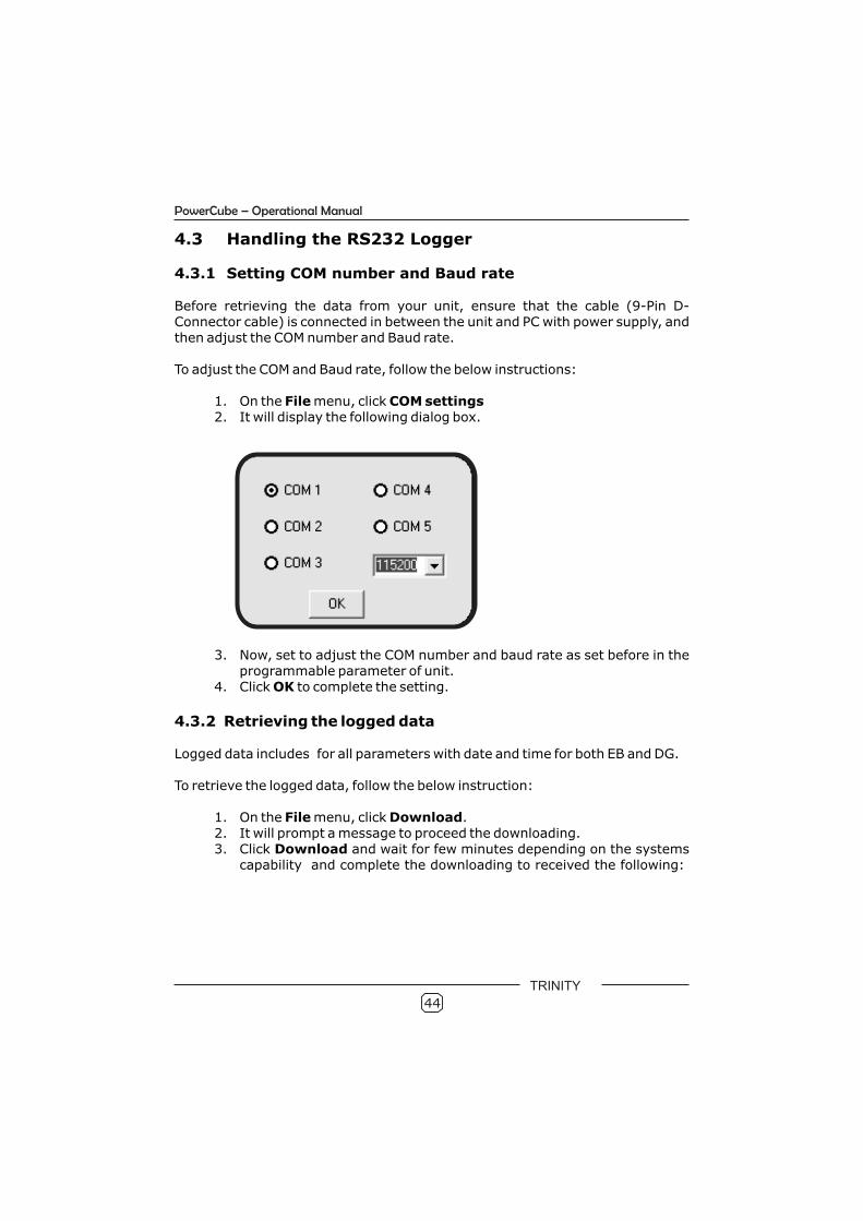
4.3.1 Setting COM number and Baud rate
Before retrieving the data from your unit, ensure that the cable (9-Pin D-Connector cable) is connected in between the unit and PC with power supply, and then adjust the COM number and Baud rate.
To adjust the COM and Baud rate, follow the below instructions:
1. On the File menu, click COM settings2. It will display the following dialog box.
3. Now, set to adjust the COM number and baud rate as set before in the programmable parameter of unit.
4. Click OK to complete the setting.
4.3.2 Retrieving the logged data
Logged data includes for all parameters with date and time for both EB and DG.
To retrieve the logged data, follow the below instruction:
1. On the File menu, click Download. 2. It will prompt a message to proceed the downloading. 3. Click Download and wait for few minutes depending on the systems
capability and complete the downloading to received the following:
TRINITY
45
PowerCube – Operational Manual
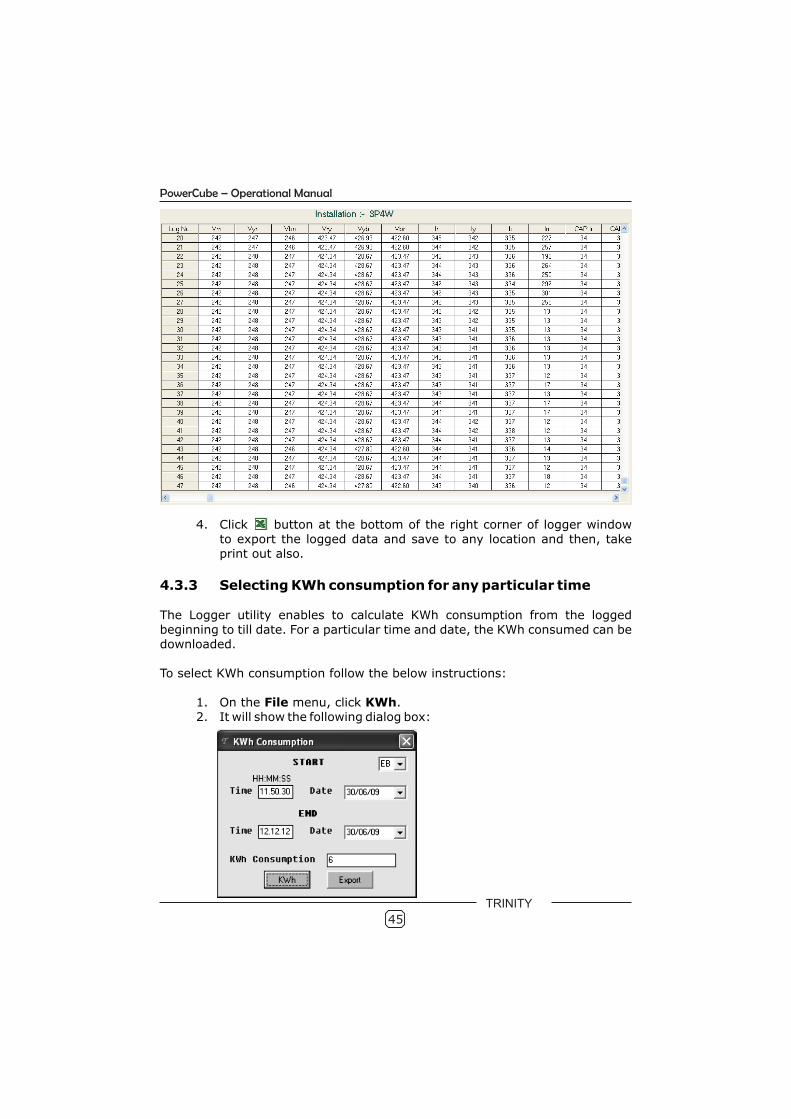
4. Click button at the bottom of the right corner of logger window to export the logged data and save to any location and then, takeprint out also.
4.3.3 Selecting KWh consumption for any particular time
The Logger utility enables to calculate KWh consumption from the logged beginning to till date. For a particular time and date, the KWh consumed can bedownloaded.
To select KWh consumption follow the below instructions:
1. On the File menu, click KWh.2. It will show the following dialog box:
TRINITY
46
PowerCube – Operational Manual
3. In time box, enter the time and in Date box, enter date and then select the types of power sources such as EB and DG. Now, clickExport to export the logged KWh for the time period entered inthe dialog box and save into excel file.
4. Click KWh to display the KWh consumption in KWh Consumption box.
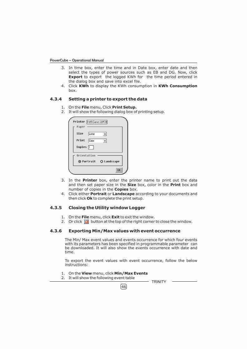
4.3.4 Setting a printer to export the data
1. On the File menu, Click Print Setup.2. It will show the following dialog box of printing setup.
3. In the Printer box, enter the printer name to print out the dataand then set paper size in the Size box, color in the Print box and
number of copies in the Copies box. 4. Click either Portrait or Landscape according to your documents and
then click Ok to complete the print setup.
4.3.5 Closing the Utility window Logger
1. On the File menu, click Exit to exit the window.2. Or click button at the top of the right corner to close the window.
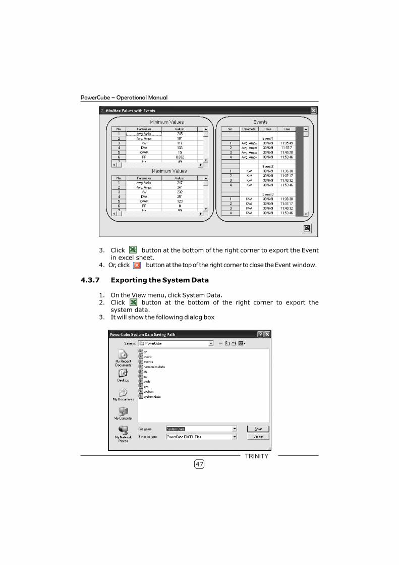
4.3.6 Exporting Min/Max values with event occurrence
The Min/ Max event values and events occurrence for which four events with its parameters has been specified in programmable parameter can be downloaded. It will also show the events occurrence with date and time.
To export the event values with event occurrence, follow the below instructions:
1. On the View menu, click Min/Max Events2. It will show the following event table
TRINITY
47
PowerCube – Operational Manual
3. Click button at the bottom of the right corner to export the Event in excel sheet.
4. Or, click button at the top of the right corner to close the Event window.
4.3.7 Exporting the System Data
1. On the View menu, click System Data.2. Click button at the bottom of the right corner to export the
system data.3. It will show the following dialog box
TRINITY
48
PowerCube – Operational Manual
4. Select the file location and enter file name in the File Name box andthen click Save to save as excel sheet. The excel will open as beforelogger system data.
5. Or click Cancel to cancel the exporting system data.
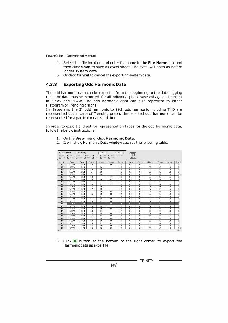
4.3.8 Exporting Odd Harmonic Data
The odd harmonic data can be exported from the beginning to the data loggingto till the data mus be exported for all individual phase wise voltage and current in 3P3W and 3P4W. The odd harmonic data can also represent to either Histogram or Trending graphs.
rdIn Histogram, the 3 odd harmonic to 29th odd harmonic including THD are represented but in case of Trending graph, the selected odd harmonic can be represented for a particular date and time.
In order to export and set for representation types for the odd harmonic data, follow the below instructions:
1. On the View menu, click Harmonic Data.2. It will show Harmonic Data window such as the following table.
3. Click button at the bottom of the right corner to export the Harmonic data as excel file.
TRINITY
49
PowerCube – Operational Manual
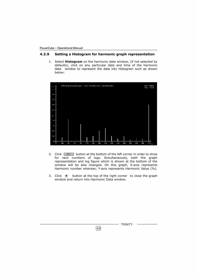
4.3.9 Setting a Histogram for harmonic graph representation
1. Select Histogram on the harmonic data window, (if not selected bydefaults), click on any particular date and time of the harmonic data window to represent the data into Histogram such as shown below:
2. Click button at the bottom of the left corner in order to showfor next numbers of logs. Simultaneously, both the graphrepresentation and log figure which is shown at the bottom of thewindow will be also changed. On this graph, X-axis representsHarmonic number whereas; Y-axis represents Harmonic Value (%).
3. Click button at the top of the right corner to close the graph window and return into Harmonic Data window.
TRINITY
50
PowerCube – Operational Manual
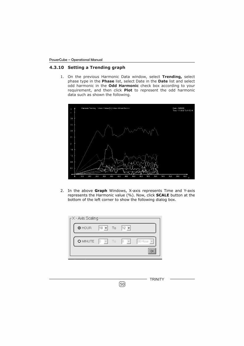
4.3.10 Setting a Trending graph
1. On the previous Harmonic Data window, select Trending, selectphase type in the Phase list, select Date in the Date list and selectodd harmonic in the Odd Harmonic check box according to yourrequirement, and then click Plot to represent the odd harmonicdata such as shown the following.
2. In the above Graph Windows, X-axis represents Time and Y-axisrepresents the Harmonic value (%). Now, click SCALE button at thebottom of the left corner to show the following dialog box.
TRINITY
51
PowerCube – Operational Manual
3. Select Hour option and in the first and second Hour list, selectHour and then click Ok to show for a Harmonic Trending withparticular time in hour.
4. Or, select Minute option and in the first and second Minute list,select Minute and then in the Hour list, select Hour. Now, click Okto show for a Harmonic Trending with particular time in minutesand hours such as shown before.
5. At the bottom of the right corner, click button to print the trending graph and then at the top of the right corner button toclose the window.
4.3.11 Displaying a Graph
Just to display the graph specified for the Harmonic data as before, this Graph option will show only for graph representation. However the color for each harmonic numbers represented on graph can be changed including X-axis and Y-axis.
To display a graph, follow the below instruction
1. On the Graph menu, click Graph2. Now, a graph will show as shown before. 3. To reset the graph according to your requirement, proceed the steps
Setting a Histogram and Setting a Trending Graph as before.
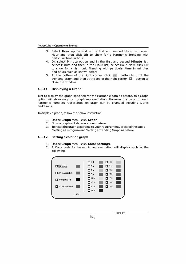
4.3.12 Setting a color on graph
1. On the Graph menu, click Color Settings.2. A Color code for harmonic representation will display such as the
following
TRINITY
52
PowerCube – Operational Manual
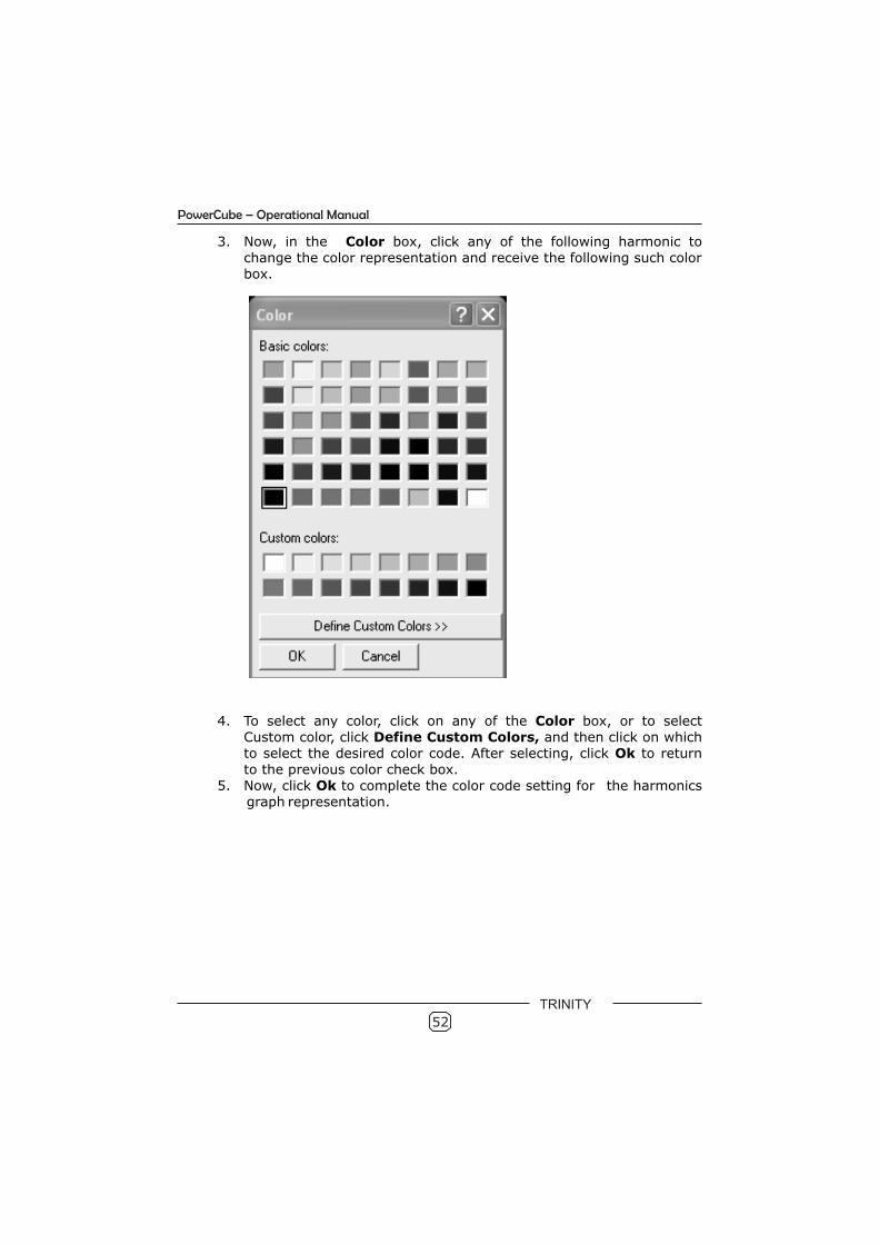
3. Now, in the Color box, click any of the following harmonic to change the color representation and receive the following such colorbox.
4. To select any color, click on any of the Color box, or to selectCustom color, click Define Custom Colors, and then click on whichto select the desired color code. After selecting, click Ok to returnto the previous color check box.
5. Now, click Ok to complete the color code setting for the harmonics graph representation.
TRINITY

5.0 Control Outputs
The relay outputs in PowerCube are in electromechanical form with contacts rated at 3A at 250V ac. There are twelve relays in PowerCube which are more than just relay outputs. These relays can be used for Alarm/Trip function or for PF correction operation. User can configure all these 12 relays for either PF (Power Factor) correction or for Alarm action.
5.1 Relays for Alarm action
In case the relays are programmed to operate for Alarm/Trip functions, each relay is independently programmable for the parameter on which to operate, time delay before operation, value for the operation to be triggered and release value. Such an alarm action can be programmed in Programming Mode on Parameter No. 22 and 29 to 34.
No. Settable Parameters Values
22 Relay Settings
30 Relay No.
31 Alarm Parameter
32 Alarm Value
33 Alarm Delay
34 Alarm Hysteresis
35 Alarm On
In the above page, after setting alarm relay 1 for KW with its value as 100, alarm type High, Alarm Delay 30 seconds and Hysteresis 5%, the relay will switch on when the system KW value exceeds 100 KW, and stays higher than that value for 30 seconds continuously. The threshold value for switching off the relay is 95 [5% Hysteresis]. Thus, the relay contact will now open when the KW value falls below 95 KW & stays that way for 30 seconds continuously.
Similarly, by selecting alarm type LOW, the relay will operate if the system KW value falls below 100KW, with the applicable delay. For this case, the threshold values for switching off the relay will be 105 KW.
Alarm Mode
01
KW
0100
30
05
High
53
PowerCube – Operational Manual
TRINITY
54
PowerCube – Operational Manual
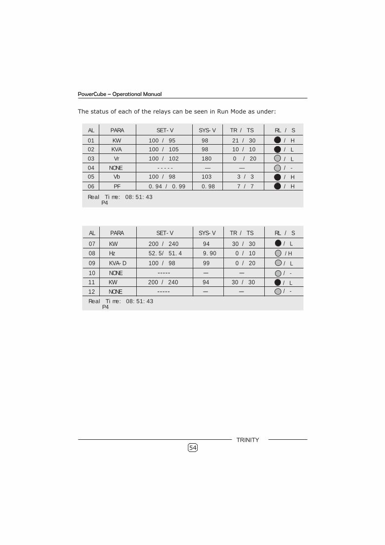
The status of each of the relays can be seen in Run Mode as under:
AL PARA SET-V SYS-V TR / TS RL / S
01 KW 100 / 95 98 21 / 30 / H
02 KVA 100 / 105 98 10 / 10
03 Vr 100 / 102 180 0 / 20
04 NONE ----- — —
05 Vb 100 / 98 103 3 / 3
06 PF 0.94 / 0.99 0.98 7 / 7
/ L
/ L
/ -
/ H
/ H
Real Time: 08:51:43 P4
AL PARA SET-V SYS-V TR / TS RL / S
08 Hz 52.5/ 51.4 9.90 0 / 10
09 KVA-D 100 / 98 99 0 / 20
07 KW 200 / 240 94 30 / 30 / L
11 KW 200 / 240 94 30 / 30 / L
/H
/ L
10 NONE ----- — — / -
12 NONE ----- — — / -
Real Time: 08:51:43 P4
TRINITY
55
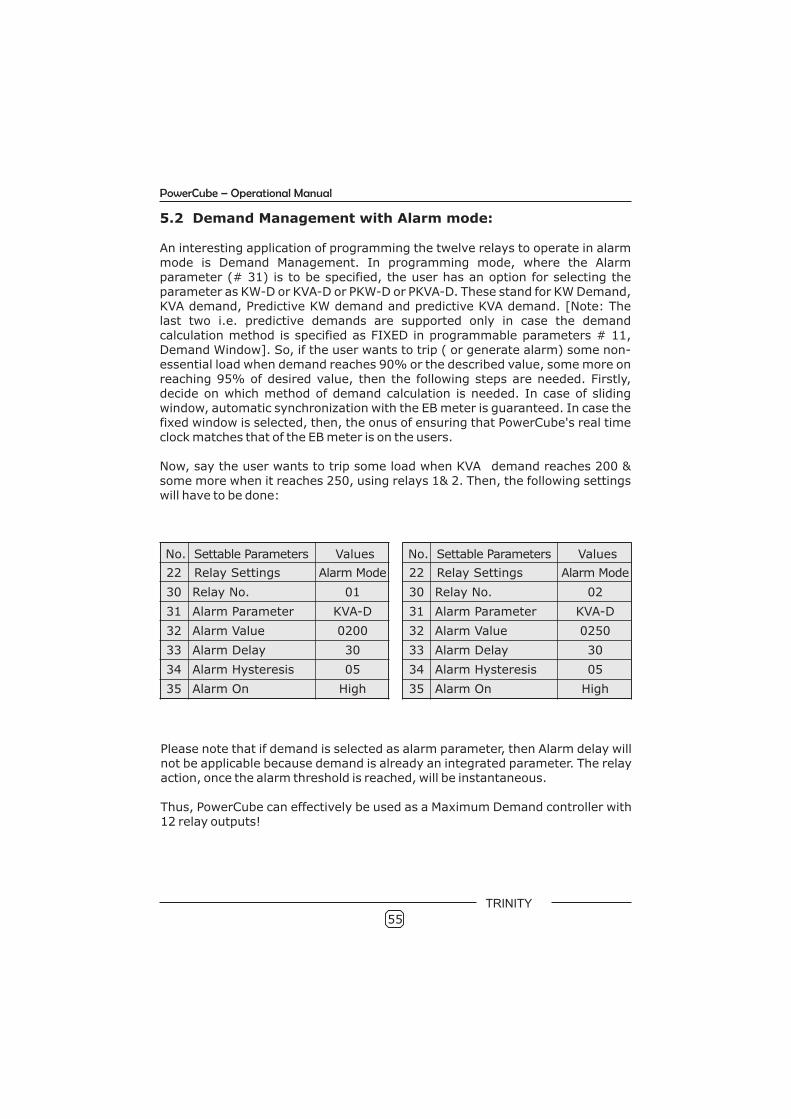
5.2 Demand Management with Alarm mode:
An interesting application of programming the twelve relays to operate in alarm mode is Demand Management. In programming mode, where the Alarm parameter (# 31) is to be specified, the user has an option for selecting the parameter as KW-D or KVA-D or PKW-D or PKVA-D. These stand for KW Demand, KVA demand, Predictive KW demand and predictive KVA demand. [Note: The last two i.e. predictive demands are supported only in case the demand calculation method is specified as FIXED in programmable parameters # 11, Demand Window]. So, if the user wants to trip ( or generate alarm) some non-essential load when demand reaches 90% or the described value, some more on reaching 95% of desired value, then the following steps are needed. Firstly, decide on which method of demand calculation is needed. In case of sliding window, automatic synchronization with the EB meter is guaranteed. In case the fixed window is selected, then, the onus of ensuring that PowerCube's real time clock matches that of the EB meter is on the users.
Now, say the user wants to trip some load when KVA demand reaches 200 & some more when it reaches 250, using relays 1& 2. Then, the following settings will have to be done:
No. Settable Parameters Values
22 Relay Settings Alarm Mode
30 Relay No. 01
31 Alarm Parameter KVA-D
32 Alarm Value 0200
33 Alarm Delay 30
34 Alarm Hysteresis 05
35 Alarm On High
No. Settable Parameters Values
22 Relay Settings Alarm Mode
30 Relay No. 02
31 Alarm Parameter KVA-D
32 Alarm Value 0250
33 Alarm Delay 30
34 Alarm Hysteresis 05
35 Alarm On High
Please note that if demand is selected as alarm parameter, then Alarm delay will not be applicable because demand is already an integrated parameter. The relay action, once the alarm threshold is reached, will be instantaneous.
Thus, PowerCube can effectively be used as a Maximum Demand controller with 12 relay outputs!
PowerCube – Operational Manual
TRINITY

56
PowerCube – Operational Manual
5.3 PF Correction
One of the special features of is to operate as a truly intelligent automatic power factor controller. It is designed to provide accurate and reliable control of Power Factor in an electrical installation.
In case user wants to use the twelve relay outputs for PF correction, PowerCube has to be programmed as shown below:
PowerCube
The significance of each of the programmable parameters for this application is as under:
# 22 Relay Settings:- specifies the relay action as PF control.
# 23 Control stages:-specifies the number of relays out of the possible ten to use for PF correction.
# 24 Control Action:- specifies the algorithm for controlling capacitors to be applied using one of the following:
BINARY/FIFO/PID/VAR.
TRINITY
No. Settable Parameters Values
22 Relay Settings PF Control
23 Control Stage 10
24 Control Action VAR
25 On Delay 30
26 Off Delay 30
27 Switching Delay 30
28 Target Pf 0.998 LD
29 Second Target PF 0.960 LG
37 Digital Input D S - Point
46 Daily Auto Sense Yes
48 Control Device Contactor
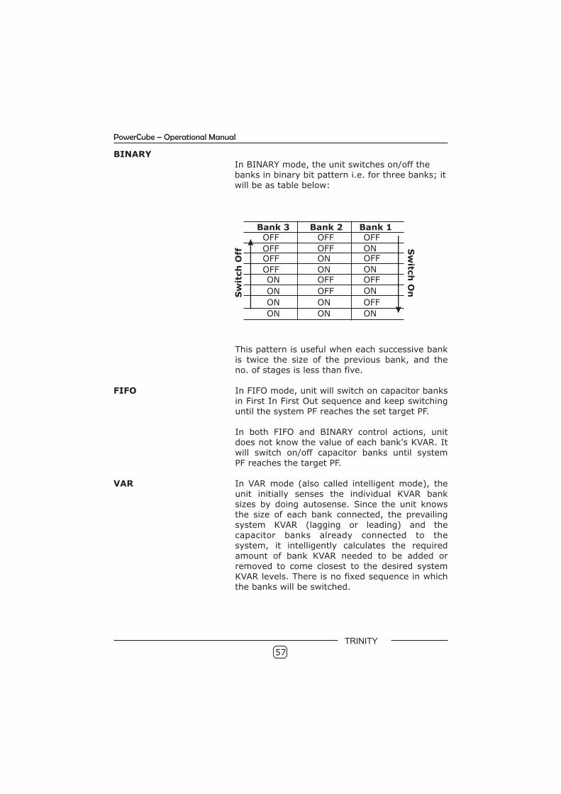
57
Bank 3 Bank 2 Bank 1OFF OFF OFF
OFF OFF ONOFF ON OFF
OFF ON ONON OFF OFF
ON OFF ON
ON ON OFF
ON ON ON
Sw
itch
Off
Sw
itch
On
This pattern is useful when each successive bank is twice the size of the previous bank, and theno. of stages is less than five.
FIFO In FIFO mode, unit will switch on capacitor banksin First In First Out sequence and keep switchinguntil the system PF reaches the set target PF.
In both FIFO and BINARY control actions, unitdoes not know the value of each bank's KVAR. Itwill switch on/off capacitor banks until systemPF reaches the target PF.
VAR In VAR mode (also called intelligent mode), the unit initially senses the individual KVAR bank sizes by doing autosense. Since the unit knows the size of each bank connected, the prevailing system KVAR (lagging or leading) and thecapacitor banks already connected to the system, it intelligently calculates the requiredamount of bank KVAR needed to be added orremoved to come closest to the desired system KVAR levels. There is no fixed sequence in whichthe banks will be switched.
BINARYIn BINARY mode, the unit switches on/off thebanks in binary bit pattern i.e. for three banks; itwill be as table below:
PowerCube – Operational Manual
TRINITY
58
PowerCube – Operational Manual
TRINITY
PID In VAR mode, before making any switching decision, the unit makes the calculations looking at the prevailing (instantaneous) system KVAR value. However, in PID mode, the unit integrates (averages) the system VAR during the switching delays period, and uses this value to determinethe next combination of banks.
In FIFO or BINARY, user can specify target PF only for LAG side whereas In VAR or PIDaction, user can set target PF either on LAGor LEAD side.
# 25 On-Delay:- specifies the time to be taken before switching on banks if system PF is less than the target PF.
# 26 OFF Delay:- specifies the time to be taken before switching off banks if system PF is more than the target PF.
# 27 Switching Delay : - After every switching of the capacitors for PF control(whether ON or OFF), PowerCube stops taking controlaction for Switching Delay (SW Delay) number of seconds. This is one type of a digital dead band.
# 28 Target PF: - specifies the desired PF to be achieved.
# 29 Second Target PF: - specifies the desired PF to be programmed only when digital input is applied (e.g. DG).
# 37 Digital Input:- specifies the usage of the potential free input, ifit is to be used for dual set point applications,then it has to be selected as D s-point. However,if any other option is selected, only target PF(single set-point) is used.
# 46 Daily Auto sense:- If this option is selected as YES, then daily at9.05 AM, the unit will run the autosenseoperation and update the capacitor bank sizes init's memory. If it is selected as NO then the userhas to run autosense manually.
#48 Control Device:- Solid State switch devices (like SSRs or Thyristors) can be switched on/off very fast, as against contactors. Also these devices do not produce huge current inrush when switched on. Hence, selecting SOLID STATE will bring on/off all stages needed simultaneously, whereas selecting CONTACTOR will switch on/off the stages, in succession (one by one) i.e not simultaneously.
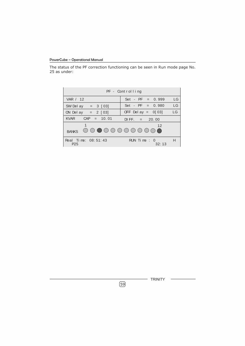
59
The status of the PF correction functioning can be seen in Run mode page No.25 as under:
PF - Controlling
VAR / 12
SW Delay = 3 [03]
ON Delay = 2 [03]
KVAR CAP = 10.01
Set - PF = 0.999 LG
Set - PF = 0.980 LG
OFF Delay = 0[03] LG
DIFF. = 20.00
BANKS
1 12
Real Time: 08:51:43 RUN Time : 0 H P25 32:13
PowerCube – Operational Manual
TRINITY
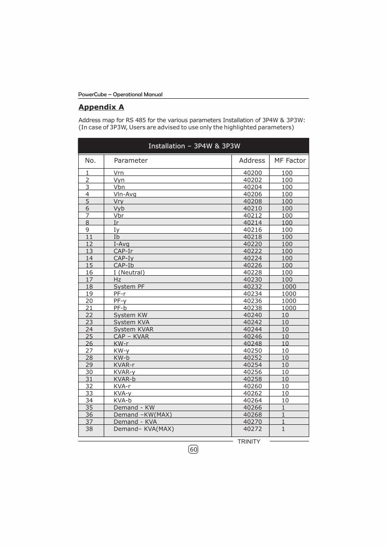
60
PowerCube – Operational Manual
Appendix A
Address map for RS 485 for the various parameters Installation of 3P4W & 3P3W: (In case of 3P3W, Users are advised to use only the highlighted parameters)
Installation – 3P4W & 3P3W
No. Parameter Address MF Factor
1 Vrn 40200 1002 Vyn 40202 1003 Vbn 40204 1004 Vln-Avg 40206 1005 Vry 40208 1006 Vyb 40210 1007 Vbr 40212 1008 Ir 40214 1009 Iy 40216 10011 Ib 40218 10012 I-Avg 40220 10013 CAP-Ir 40222 10014 CAP-Iy 40224 10015 CAP-Ib 40226 10016 I (Neutral) 40228 10017 Hz 40230 10018 System PF 40232 100019 PF-r 40234 100020 PF-y 40236 100021 PF-b 40238 100022 System KW 40240 1023 System KVA 40242 1024 System KVAR 40244 1025 CAP – KVAR 40246 1026 KW-r 40248 1027 KW-y 40250 1028 KW-b 40252 1029 KVAR-r 40254 1030 KVAR-y 40256 1031 KVAR-b 40258 1032 KVA-r 40260 1033 KVA-y 40262 1034 KVA-b 40264 1035 Demand - KW 40266 136 Demand –KW(MAX) 40268 137 Demand - KVA 40270 138 Demand– KVA(MAX) 40272 1
TRINITY
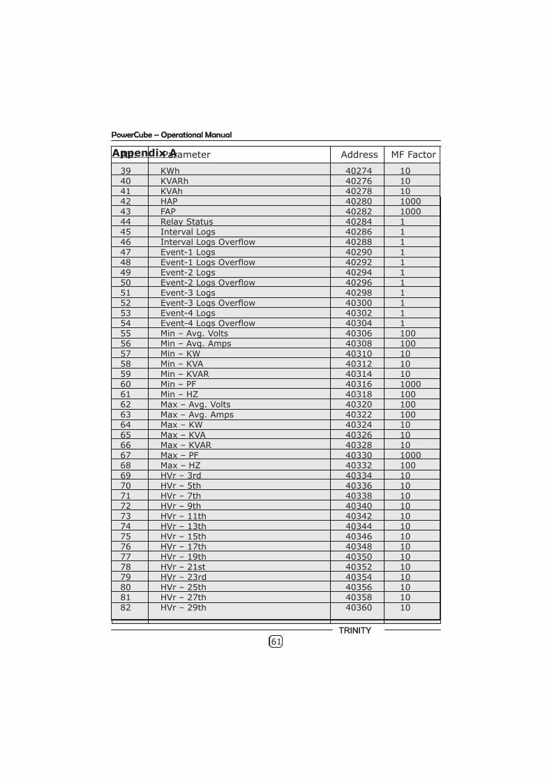
60
PowerCube – Operational Manual
Appendix A
Address map for RS 485 for the various parameters Installation of 3P4W & 3P3W: (In case of 3P3W, Users are advised to use only the highlighted parameters)
Installation – 3P4W & 3P3W
No. Parameter Address MF Factor
1 Vrn 40200 1002 Vyn 40202 1003 Vbn 40204 1004 Vln-Avg 40206 1005 Vry 40208 1006 Vyb 40210 1007 Vbr 40212 1008 Ir 40214 1009 Iy 40216 10011 Ib 40218 10012 I-Avg 40220 10013 CAP-Ir 40222 10014 CAP-Iy 40224 10015 CAP-Ib 40226 10016 I (Neutral) 40228 10017 Hz 40230 10018 System PF 40232 100019 PF-r 40234 100020 PF-y 40236 100021 PF-b 40238 100022 System KW 40240 1023 System KVA 40242 1024 System KVAR 40244 1025 CAP – KVAR 40246 1026 KW-r 40248 1027 KW-y 40250 1028 KW-b 40252 1029 KVAR-r 40254 1030 KVAR-y 40256 1031 KVAR-b 40258 1032 KVA-r 40260 1033 KVA-y 40262 1034 KVA-b 40264 1035 Demand - KW 40266 136 Demand –KW(MAX) 40268 137 Demand - KVA 40270 138 Demand– KVA(MAX) 40272 1
TRINITY
No. Parameter Address MF Factor
39 KWh 40274 1040 KVARh 40276 1041 KVAh 40278 1042 HAP 40280 100043 FAP 40282 100044 Relay Status 40284 145 Interval Logs 40286 146 Interval Logs Overflow 40288 147 Event-1 Logs 40290 148 Event-1 Logs Overflow 40292 149 Event-2 Logs 40294 150 Event-2 Logs Overflow 40296 151 Event-3 Logs 40298 152 Event-3 Logs Overflow 40300 153 Event-4 Logs 40302 154 Event-4 Logs Overflow 40304 155 Min – Avg. Volts 40306 10056 Min – Avg. Amps 40308 10057 Min – KW 40310 1058 Min – KVA 40312 1059 Min – KVAR 40314 1060 Min – PF 40316 100061 Min – HZ 40318 10062 Max – Avg. Volts 40320 10063 Max – Avg. Amps 40322 10064 Max – KW 40324 1065 Max – KVA 40326 1066 Max – KVAR 40328 1067 Max – PF 40330 100068 Max – HZ 40332 10069 HVr – 3rd 40334 1070 HVr – 5th 40336 1071 HVr – 7th 40338 1072 HVr – 9th 40340 1073 HVr – 11th 40342 1074 HVr – 13th 40344 1075 HVr – 15th 40346 1076 HVr – 17th 40348 1077 HVr – 19th 40350 1078 HVr – 21st 40352 1079 HVr – 23rd 40354 1080 HVr – 25th 40356 1081 HVr – 27th 40358 1082 HVr – 29th 40360 10
61
PowerCube – Operational Manual
TRINITY
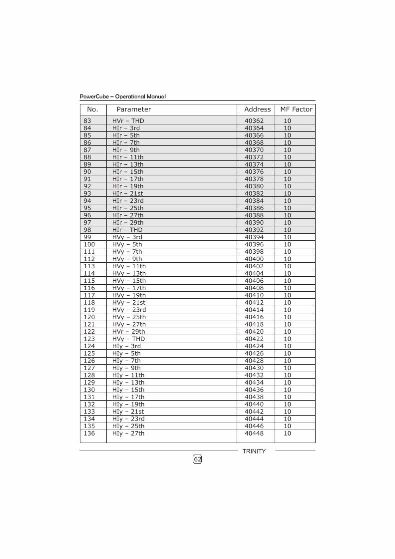
62
No. Parameter Address MF Factor
83 HVr – THD 40362 1084 HIr – 3rd 40364 1085 HIr – 5th 40366 1086 HIr – 7th 40368 1087 HIr – 9th 40370 1088 HIr – 11th 40372 1089 HIr – 13th 40374 1090 HIr – 15th 40376 1091 HIr – 17th 40378 1092 HIr – 19th 40380 1093 HIr – 21st 40382 1094 HIr – 23rd 40384 1095 HIr – 25th 40386 1096 HIr – 27th 40388 1097 HIr – 29th 40390 1098 HIr – THD 40392 1099 HVy – 3rd 40394 10100 HVy – 5th 40396 10111 HVy – 7th 40398 10112 HVy – 9th 40400 10113 HVy – 11th 40402 10114 HVy – 13th 40404 10115 HVy – 15th 40406 10116 HVy – 17th 40408 10117 HVy – 19th 40410 10118 HVy – 21st 40412 10119 HVy – 23rd 40414 10120 HVy – 25th 40416 10121 HVy – 27th 40418 10122 HVr – 29th 40420 10123 HVy – THD 40422 10124 HIy – 3rd 40424 10125 HIy – 5th 40426 10126 HIy – 7th 40428 10127 HIy – 9th 40430 10128 HIy – 11th 40432 10129 HIy – 13th 40434 10130 HIy – 15th 40436 10131 HIy – 17th 40438 10132 HIy – 19th 40440 10133 HIy – 21st 40442 10134 HIy – 23rd 40444 10135 HIy – 25th 40446 10136 HIy – 27th 40448 10
PowerCube – Operational Manual
TRINITY
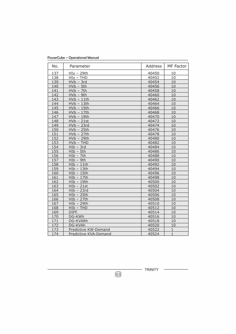
No. Parameter Address MF Factor
137 HIy – 29th 40450 10138 HIy – THD 40452 10139 HVb – 3rd 40454 10140 HVb – 5th 40456 10141 HVb – 7th 40458 10142 HVb – 9th 40460 10143 HVb – 11th 40462 10144 HVb – 13th 40464 10145 HVb – 15th 40466 10146 HVb – 17th 40468 10147 HVb – 19th 40470 10148 HVb – 21st 40472 10149 HVb – 23rd 40474 10150 HVb – 25th 40476 10151 HVb – 27th 40478 10152 HVb – 29th 40480 10153 HVb – THD 40482 10154 HIb – 3rd 40484 10155 HIb – 5th 40486 10156 HIb – 7th 40488 10157 HIb – 9th 40490 10158 HIb – 11th 40492 10159 HIb – 13th 40494 10160 HIb – 15th 40496 10161 HIb – 17th 40498 10162 HIb – 19th 40500 10163 HIb – 21st 40502 10164 HIb – 23rd 40504 10165 HIb – 25th 40506 10166 HIb – 27th 40508 10167 HIb – 29th 40510 10168 HIb – THD 40512 10169 DIFF. 40514 10170 DG-KWh 40516 10171 DG-KVARh 40518 10172 DG-KVAh 40520 10173 Predictive KW-Demand 40522 1174 Predictive KVA-Demand 40524 1
TRINITY
63
PowerCube – Operational Manual

TRINITY
PowerCube – Operational Manual
P.O. No. : …………………………………………………………………
Customer : …………………………………………………………………
Sr. No. : …………………………………………………………………
Routine and function tests conducted to relevant standards and our Specifications/Literature/O & M Manual. Traceability: tested against "MTE" Standard Model PRS1.3 having basic accuracy of 0.05% traceable upto International Standards derived using appropriate ratio techniques.
Result of Test : …………………………………………………………………
Remarks : …………………………………………………………………
Test engineer : …………………………………………………………………
Date : …………………………………………………………………

TRINITY ENERGY SYSTEMS PVT. LTD.366/A/12, G.I.D.C. Estate, Makarpura, VADODARA-390010, Gujarat, India
Tele/ Fax. : 0265 - 2645738/ 2633270/ 2632761email : [email protected]
web : www.trinityenergy.co.in