user’s guide - frank's hospital workshop · user’s guide including: ... spo 2 monitoring...
TRANSCRIPT

User’s Guide
Including:
•HP M2475B CodeMaster 100 Portable Defibrillator/Monitor with 12-Lead ECG option
•HP M2480B Battery Support System
•HP M2478A DC Power Module
•HP M2479A AC Power Module
HP CodeMaster 100 Portable Defibrillator/Monitor+3�3DUW�1R��0����������3ULQWHG�LQ�86$�)HEUXDU\�����
(GLWLRQ��

Notice
ii
0Notice
The information in this document is subject to change without notice.
Hewlett-Packard makes no warranty of any kind on this material, including but not limited to, the implied warranties of merchantability and fitness for a particular purpose. Hewlett-Packard shall not be liable for errors contained herein, or for incidental or consequential damages in connection with the furnishing, performance, or use of this material.
This document contains proprietary information which is protected by copyright. All rights are reserved. No part of this document may be photocopied, reproduced, or translated to another language without the prior written consent of Hewlett-Packard Company.
Before using the HP CodeMaster 100 , the battery support system, or the power modules, read this guide and become thoroughly familiar with the contents.
Responsibility of the Manufacturer
Hewlett-Packard only considers itself responsible for any effects on safety, reliability and performance of the HP CodeMaster 100 , the battery support system and the power modules if:
•assembly operations, extensions, re-adjustments, modifications or repairs are done by persons authorized by Hewlett-Packard, and
•the electrical installation complies with the IEC or national requirements, and
•the instrument is used according to the instructions for use presented in this manual.

Notice
iii
As with all electronic equipment, Electromagnetic Interference (EMI) between the defibrillator and any existing EMI transmitting or receiving equipment at the installation site, including electrosurgical equipment, should be evaluated carefully and any limitations noted before the equipment is placed in service.
Do not attempt to perform pacing during surgery. Monitoring during quiescent periods of electrosurgery is possible but electromagnetic interference generated by electrosurgical tools during operation is sufficient to mask cardiac signals. A momentary recovery period is required for the monitor to return to normal operation and will be longer if the diagnostic monitoring mode is used. Defib or monitoring electrodes should be placed as far from the surgical area as reasonable while still performing normal functions to minimize the possibility of burns. EMI frequency generation from electrosurgical equipment and close proximity transmitters may seriously degrade performance of the HP CodeMaster 100 .
Hewlett-Packard assumes no liability for failures resulting from EMI between HP medical electronics and any radio frequency generating equipment at levels exceeding those established by applicable standards.
Federal law (USA) restricts this device to sale by or on the order of a physician.
THIS PRODUCT IS NOT INTENDED FOR HOME USE.
This product complies with the requirements of the Medical Device Directive 93/42/EEC and carries the CE0123 marking accordingly. Authorized EU-representative: Hewlett-Packard GmbH, Department MPG-E Regulations, Herrenberger Str. 110-140, 71034 Boblingen (FAX: +49-7031-14-2346)
This product complies with the telecom regulatory standards for internal modems set by the Federal Communications Commission (FCC) in the United States, Industry Canada, and the Department of Trade and Industry in the United Kingdom.
WARNING
CAUTION

Notice
iv
Associated Documents
Printing History
February 26, 1999 Edition1
Copyright © 1999Hewlett-Packard CompanyAndover, MA 01810, USA
Document Title HP Part Number
HP M2475B CodeMaster 100 Portable Defibrillator/Monitor Quick Reference Guide
M2475-97800
HP CodeMaster Series Defibrillator/Monitor Pacing Application Note
M1722-94920
Understanding Pulse OximetrySpO2 Concepts
M1722-93950
HP M2475B CodeMaster 100 Portable Defibrillator/Monitor Service Manual
M2475-90905
Sensor Guide M1722-93970
Predictive Instruments Physician’s Guide M1792-93900
HP M2476B & M2477B Battery Evaluation and Care
M2475-92100
M3710A Carry Bag Instructions for Use M2475-94000
Symbol Definitions
v
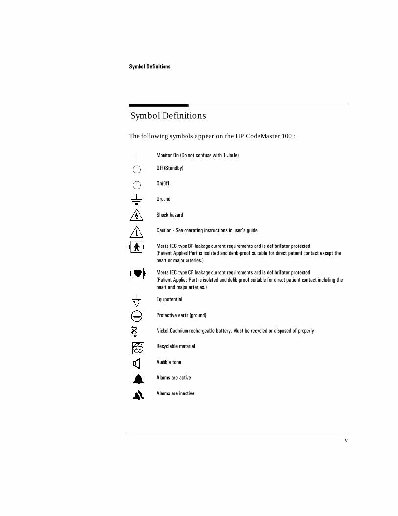
0Symbol Definitions
The following symbols appear on the HP CodeMaster 100 :
0RQLWRU�2Q��'R�QRW�FRQIXVH�ZLWK���-RXOH�
2II��6WDQGE\��
2Q�2II
*URXQG
6KRFN�KD]DUG
&DXWLRQ���6HH�RSHUDWLQJ�LQVWUXFWLRQV�LQ�XVHU·V�JXLGH
0HHWV�,(&�W\SH�%)�OHDNDJH�FXUUHQW�UHTXLUHPHQWV�DQG�LV�GHILEULOODWRU�SURWHFWHG�3DWLHQW�$SSOLHG�3DUW�LV�LVRODWHG�DQG�GHILE�SURRI�VXLWDEOH�IRU�GLUHFW�SDWLHQW�FRQWDFW�H[FHSW�WKH�KHDUW�RU�PDMRU�DUWHULHV��
0HHWV�,(&�W\SH�&)�OHDNDJH�FXUUHQW�UHTXLUHPHQWV�DQG�LV�GHILEULOODWRU�SURWHFWHG�3DWLHQW�$SSOLHG�3DUW�LV�LVRODWHG�DQG�GHILE�SURRI�VXLWDEOH�IRU�GLUHFW�SDWLHQW�FRQWDFW�LQFOXGLQJ�WKH�KHDUW�DQG�PDMRU�DUWHULHV��
(TXLSRWHQWLDO�
3URWHFWLYH�HDUWK��JURXQG�
1LFNHO�&DGPLXP�UHFKDUJHDEOH�EDWWHU\��0XVW�EH�UHF\FOHG�RU�GLVSRVHG�RI�SURSHUO\
5HF\FODEOH�PDWHULDO
$XGLEOH�WRQH
$ODUPV�DUH�DFWLYH
$ODUPV�DUH�LQDFWLYH
1L�&G

Symbol Definitions
vi
The following symbols appear on the HP M2480B battery support system.
The following symbols appear on the HP M2478A DC power module.
The following symbols appear on the HP M2479A AC power module:
'R�QRW�XVH�LQ�WKH�SUHVHQFH�RI�IODPPDEOH�DQHVWKHWLFV�RU�LQ�R[\JHQ�ULFK�HQYLURQPHQWV
$&�SRZHU�RQ
6WDUW�EDWWHU\�FDSDFLW\�WHVW
%DWWHU\�FKDUJLQJ
%DWWHU\�FDSDFLW\�WHVW
$GGLWLRQDO�LQIRUPDWLRQ
3RZHU
&DXWLRQ���6HH�RSHUDWLQJ�LQVWUXFWLRQV
%DWWHU\�FKDUJLQJ
'&�SRZHU
,QSXW
2XWSXW
$WWHQWLRQ���6HH�RSHUDWLQJ�LQVWUXFWLRQV�
*UHHQ�/('��SRZHU�RQ�
%DWWHU\�FKDUJLQJ�3URWHFWLYH�HDUWK��JURXQG��
'&�SRZHU� $&�$OWHUQDWLQJ�FXUUHQW
)XVH�UHSODFHPHQW�YDOXH 2XWSXW

Conventions
vii
0Conventions
This manual uses the following conventions:
Warning statements describe conditions or actions that can result in personal injury or loss of life.
Caution statements describe conditions or actions that can result in damage to the equipment or loss of data.
Notes contain additional information on usage.
TEXT represents the labels that appear on the display.
Bold represents buttons/controls on the device.
Bold Italic represents softkeys (temporary key labels) that appear on the 12-Lead display.
WARNING
CAUTION
NOTE

Preface
viii
0Preface
Introduction
This Preface provides general information which you should review before using the HP M2475B CodeMaster 100 Portable Defibrillator/Monitor with 12-Lead ECG option.
About the HP Codemaster 100
The HP CodeMaster 100 is a portable, battery-powered defibrillator/monitor with built in non-invasive pacing, pulse oximetry (SpO2), and 3- or 5-wire ECG monitoring capability. It also offers an optional Shock Advisory mode as well as an option to acquire a 12-lead ECG. The Shock Advisory mode detects whether the rhythm is shockable and guides the user through the process of defibrillation. It comes with an Advisory Event Summary to simplify documentation. The 12-lead ECG option allows users to acquire, store, and transmit 12-lead ECGs for help with early detection of acute cardiac ischemia, acute myocardial infarction and other arrhythmias.
The HP CodeMaster 100 is used as an advanced defibrillator/monitor in the pre-hospital arena and as a transport defibrillator in the hospital environment. It can be used with adult paddles, pediatric paddles, and multi-function defib electrodes. Multi-function defib electrodes allow the user to pace, monitor, and defibrillate from the same electrodes.
Theory of Defibrillator Operation
Defibrillation is a recognized means of terminating certain potentially fatal arrhythmias, such as ventricular fibrillation and symptomatic ventricular tachycardia. A direct current defibrillator applies a brief, high-energy pulse of electricity to the heart muscle (up to 360 joules). The HP CodeMaster 100 delivers this energy through multi-function defib electrodes or paddles applied to the patient’s chest. Delivery of this energy in the synchronized mode is useful in treating supraventricular tachycardia, atrial fibrillation, atrial flutter, and, in relatively stable patients, ventricular tachycardia.

Preface
ix
Intended Use
The HP CodeMaster 100 is for use by emergency care personnel specifically trained in the operation of the device and qualified by training in advanced cardiac life support, basic life support or other physician-authorized emergency medical response. It must be used by or on the order of a physician.
When operating as a manual defibrillator, the HP CodeMaster 100 is suitable for use by personnel trained in advanced cardiac life support. In Shock Advisory Mode, the HP CodeMaster 100 is suitable for use by EMS personnel with basic life support training.
Indications and Contraindications
Defibrillation
Indications
Defibrillation therapy is indicated for patients that exhibit the following combination of symptoms:
•unconsciousness
•absence of breathing
•absence of detectable pulse
•ventricular fibrillation or ventricular tachycardia

Preface
x
Defibrillation
Contraindications
Defibrillation therapy is contraindicated for patient that exhibit any of the following:
•consciousness
•presence of breathing
•presence of detectable pulse
In addition, the HP CodeMaster 100 should not be used in Shock Advisory Mode (where it functions like an AED) for:
•children who weigh under 90 pounds
•patients who have an implanted pacemaker
The shock advisory algorithm is not designed or tested to interpret pediatric cardiac arrhythmias or administer energy at pediatric joule settings. For children older than 8 years, the American heart Association recommends that standard operating procedures for AEDs be followed. American heart Association Textbook of Advanced Cardiac Life Support. Dallas, Tex.: AHA;1994.
The shock advisory algorithm is not designed to handle erratic spiking problems caused by a properly or improperly functioning pacemaker.
NOTE
NOTE

Preface
xi
Noninvasive Pacing
Indications
The HP CodeMaster 100 provides non-invasive pacing that delivers an electrical stimulus to the heart, causing cardiac depolarization and myocardial contraction. The energy is delivered through multifunction defib electrodes placed on the chest. Non-invasive pacing, as a therapy, is indicated for use in patients with symptomatic bradycardia or asystole. In addition to noninvasive pacing, other supportive measures may be necessary.
Among other factors, successful pacing of a patient is related to the length of time between the onset of a dysrhythmia and the initiation of pacing. Rapid pacing and prompt follow-up care are essential. The physiologic state of the patient may affect the likelihood of successful pacing or of skeletal muscle activity. The failure to successfully pace a patient is not a reliable indicator of pacemaker performance. Similarly, the patient’s muscular response to pacing is not a reliable indicator of energy delivered.
Contraindications
Contraindications for noninvasive pacing include ventricular fibrillation.

Preface
xii
12-Lead Electrocardiography
Indications
The American Heart Association (AHA) and the National Heart Attack Alert Program (NHAAP) recommend prehospital 12-Lead ECG with computer analysis and transmission to the emergency department for patients with chest pain and possible Acute Myocardial Infarction (AMI).
The prehospital 12-Lead ECG offers paramedics and emergency physicians significant advantages over the single lead ECG typically available in EMS. The prehospital 12-Lead ECG not only provides a diagnostic quality ECG for use in the detection of AMI, but also allows the knowledgeable paramedic to determine the area of myocardial injury, anticipate associated potential complications, and implement treatment strategies accordingly. In addition, the prehospital 12-Lead ECG provides a baseline for serial ECG evaluations.
Contraindications
None known.
SpO2 Monitoring
Indications
Pulse oximetry through plethmography (SpO2) is a measure of oxygen saturation in arterial blood. It is indicated for use when determining a patient’s level of hypoxemia.
Contraindications
None known.

Preface
xiii
Electromagnetic Compatibility
:KHQ�XVLQJ�WKH�+3�&RGH0DVWHU�������ZLWK�RU�ZLWKRXW�WKH�H[WHUQDO�3RZHU�0RGXOH���HOHFWURPDJQHWLF�FRPSDWLELOLW\�ZLWK�VXUURXQGLQJ�GHYLFHV�VKRXOG�EH�DVVHVVHG��
$�PHGLFDO�GHYLFH�FDQ�HLWKHU�JHQHUDWH�RU�UHFHLYH�HOHFWURPDJQHWLF�LQWHUIHUHQFH�����7HVWLQJ�IRU�HOHFWURPDJQHWLF�FRPSDWLELOLW\��(0&��KDV�EHHQ�SHUIRUPHG�DFFRUGLQJ�WR�WKH�LQWHUQDWLRQDO�VWDQGDUG�IRU�(0&�IRU�PHGLFDO�GHYLFHV��,(&�����������7KLV�,(&�VWDQGDUG�KDV�EHHQ�DGRSWHG�LQ�(XURSH�DV�WKH�(XURSHDQ�1RUP��(1�������������
7KH�(0&�VWDQGDUGV�GHVFULEH�WHVWV�IRU�ERWK�HPLWWHG�DQG�UHFHLYHG�LQWHUIHUHQFH��(PLVVLRQ�WHVWV�GHDO�ZLWK�LQWHUIHUHQFH�JHQHUDWHG�E\�WKH�GHYLFH�EHLQJ�WHVWHG��$FFRUGLQJ�WR�WKH�(0&�VWDQGDUGV��WKH�&RGH0DVWHU�����GHILEULOODWRU�PRQLWRU�GRHV�QRW�JHQHUDWH�DEQRUPDO�LQWHUIHUHQFH��
Reducing Electromagnetic Interference
7KH�+3�&RGH0DVWHU������LV�VXVFHSWLEOH�WR�LQWHUIHUHQFH�IURP�RWKHU�5)�HQHUJ\�VRXUFHV�DQG�FRQWLQXRXV��UHSHWLWLYH��SRZHU�OLQH�EXUVWV��([DPSOHV�RI�RWKHU�VRXUFHV�RI�5)�LQWHUIHUHQFH�DUH�PHGLFDO�GHYLFHV��FHOOXODU�SURGXFWV��LQIRUPDWLRQ�WHFKQRORJ\�HTXLSPHQW�DQG�UDGLR�WHOHYLVLRQ�WUDQVPLVVLRQ��6KRXOG�LQWHUIHUHQFH�EH�HQFRXQWHUHG��DV�GHPRQVWUDWHG�E\�DUWLIDFW�RQ�WKH�(&*�RU�GUDPDWLF�YDULDWLRQV�LQ�6S2��YDOXHV��DWWHPSW�WR�ORFDWH�WKH�VRXUFH��$VVHVV�WKH�IROORZLQJ�
���,V�WKH�LQWHUIHUHQFH�LQWHUPLWWHQW�RU�FRQVWDQW"
���'RHV�WKH�LQWHUIHUHQFH�RFFXU�RQO\�LQ�FHUWDLQ�ORFDWLRQV"
���'RHV�WKH�LQWHUIHUHQFH�RFFXU�RQO\�ZKHQ�LQ�FORVH�SUR[LPLW\�WR�FHUWDLQ�PHGL�FDO�GHYLFHV"
���'RHV�WKH�6S2��YDOXH�FKDQJH�GUDPDWLFDOO\�ZKHQ�WKH�H[WHUQDO�GHYLFH�LV�XQSOXJJHG"
2QFH�WKH�VRXUFH�LV�ORFDWHG��DWWHPSW�WR�DWWHQXDWH�WKH�(0&�FRXSOLQJ�SDWK�E\�GLVWDQFLQJ�WKH�GHILEULOODWRU�IURP�WKH�VRXUFH�DV�PXFK�DV�SRVVLEOH��,I�DVVLVWDQFH�LV�QHHGHG��FDOO�\RXU�ORFDO�+3�VHUYLFH�UHSUHVHQWDWLYH�

Preface
xiv
Restrictions for Use
$UWLIDFW�RQ�WKH�(&*�FDXVHG�E\�HOHFWURPDJQHWLF�LQWHUIHUHQFH�VKRXOG�EH�HYDOXDWHG�E\�D�SK\VLFLDQ�RU�SK\VLFLDQ�DXWKRUL]HG�SHUVRQQHO�WR�GHWHUPLQH�LI�LW�ZLOO�QHJDWLYHO\�LPSDFW�SDWLHQW�GLDJQRVLV�RU�WUHDWPHQW��
Immunity Level
7KH�(0&�VWDQGDUGV�VWDWH�WKDW�PDQXIDFWXUHUV�RI�SDWLHQW�FRXSOHG�HTXLSPHQW�PXVW�VSHFLI\�LPPXQLW\�OHYHOV�IRU�WKHLU�V\VWHPV��,W�LV�UHFRJQL]HG�WKDW�WKH�+3�&RGH0DVWHU������LV�GHVLJQHG�WR�UHFHLYH�DQG�DPSOLI\�ORZ�OHYHO�VLJQDOV�LQ�WKH�VDPH�EDQGZLGWK�DV�WKH�LQWHUIHUHQFH�
,PPXQLW\�LV�GHILQHG�LQ�WKH�VWDQGDUG�DV�WKH�DELOLW\�RI�D�V\VWHP�WR�SHUIRUP�ZLWKRXW�GHJUDGDWLRQ�LQ�WKH�SUHVHQFH�RI�DQ�HOHFWURPDJQHWLF�GLVWXUEDQFH��'HJUDGDWLRQ�LQ�(&*�TXDOLW\�LV�D�TXDOLWDWLYH�DVVHVVPHQW�ZKLFK�FDQ�EH�VXEMHFWLYH��
&DXWLRQ�VKRXOG��WKHUHIRUH��EH�WDNHQ�LQ�FRPSDULQJ�LPPXQLW\�OHYHOV�RI�GLIIHUHQW�GHYLFHV��7KH�FULWHULD�XVHG�IRU�GHJUDGDWLRQ�DUH�QRW�VSHFLILHG�E\�WKH�VWDQGDUG�DQG�PD\�YDU\�ZLWK�WKH�PDQXIDFWXUHU�
)RU�DGGLWLRQDO�LQIRUPDWLRQ�DERXW�FRPSOLDQFH�ZLWK�WKH�(0&�VWDQGDUGV��SOHDVH�VHH�WKH�'HFODUDWLRQ�RI�&RQIRUPLW\�6WDWHPHQW�VKLSSHG�ZLWK�WKH�GHYLFH�
NOTE
Telecom Regulatory Information
xv
0Telecom Regulatory Information
United States
In compliance with the Federal Communications Commission (FCC), the following information is provided:
• This equipment complies with Part 68 of the FCC rules. This unit bears a label which contains the FCC registration number and Ringer Equivalence Number. If requested, this information must be provided to the telephone company.
• This equipment uses the following standard jack types for network connection: RJ11C.
• This equipment contains an FCC compliant modular jack. It is designed to be con-nected to the on-premises telephone network wiring using compatible modular plugs and cabling which complies with the requirements of FCC Part 68 rules.
• The Ringer Equivalence Number, or REN, is used to determine the number of devices that may be connected to the telephone line. An excessive REN may cause the equipment not to ring in response to an incoming call. In most areas, the sum of the REN’s of all equipment on a line should not exceed five (5.0).
• In the unlikely event that this equipment causes harm to the telephone network, the telephone company can temporarily disconnect your service. The telephone com-pany will try to warn you in advance of any such disconnection, but if advance notice isn’t practical, it may disconnect the service first and notify you afterwards. In the event such a disconnection is deemed necessary, you will be advised of your right to file a complaint with the FCC.
• From time to time, the telephone company may make changes in its facilities, equipment, or operations which could affect the operation of this equipment. If this occurs, the telephone company is required to provide you with advance notice so that you can make the modifications necessary to maintain uninterrupted service.
• For servicing information, see “Service” on page 12-21.
• For troubleshooting transmission problems, see “Identifying Transmission Prob-lems” on page 12-17.

Telecom Regulatory Information
xvi
Canada
In compliance with the Industry Canada, the following information is provided:
• NOTICE: The Industry Canada label identifies certified equipment. This certifica-tion means that the equipment meets telecommunications network protective Technical Requirements document(s). The department does not guarantee the equipment will operate to the user’s satisfaction.
• Before connecting this equipment, users should ensure that it is permissible to be connected to the facilities of the local telecommunications company. The equip-ment must also use an acceptable method of connection. The customer should be aware that compliance with the above conditions may not prevent degradation of service in some situations.
• Repairs to certified equipment should be coordinated by a representative desig-nated by Hewlett-Packard. Any repairs or alterations made by the user to this equipment, or equipment malfunctions, may give the telecommunications com-pany cause to request the user to disconnect the equipment.
• Users should ensure, for their own protection, that the electrical ground connec-tions of the power utility, telephone lines and internal metallic water pipe system, if present, are connected together. This precaution may not be particularly impor-tant in rural areas.
Users should not attempt to make electrical ground connections themselves, but should contact the appropriate electric inspection authority, or electrician, as appropriate.
• NOTICE: The Ringer Equivalence Number (REN) assigned to each terminal device provides an indication of the maximum number of terminals allowed to be connected to a telephone interface. The termination on an interface may consist of any combination of devices subject only to the requirement that the sum of the Ringer Equivalence Numbers of all the devices does not exceed five (5.0).
CAUTION

Telecom Regulatory Information
xvii
United Kingdom
In compliance with the Department of Trade and Industry, the following information is provided:
Although this equipment can use either loop disconnect or DTMF signaling, only DTMF signaling is subject to regulatory requirements for correct operation. It is, therefore, strongly recommended that the equipment is set to use DTMF signaling for access to public or private emergency services. DTMF signaling also provides faster call set up.

Telecom Regulatory Information
xviii

xix
Contents
Notice iiResponsibility of the Manufacturer iiAssociated Documents ivPrinting History iv
Symbol Definitions v
Conventions vii
Preface viiiIntroduction viiiAbout the HP Codemaster 100 viiiTheory of Defibrillator Operation viiiIntended Use ixIndications and Contraindications ix
Defibrillation ixDefibrillation xNoninvasive Pacing xi12-Lead Electrocardiography xiiIndications xiiContraindications xiiSpO2 Monitoring xiiIndications xiiContraindications xii
Electromagnetic Compatibility xiiiReducing Electromagnetic Interference xiiiRestrictions for Use xivImmunity Level xiv
Telecom Regulatory Information xvUnited States xvCanada xviUnited Kingdom xvii
1 Getting Acquainted
Operating Controls and Indicators 1-4Defibrillator Operating Controls 1-4Monitor Operating Controls 1-7

xx
Recorder Operating Controls 1-9Pacer Operating Controls 1-11SpO2 Operating Controls 1-13
SpO2 Operating Controls 1-14Advisory Mode Operating Controls (Optional) 1-1512-Lead Operating Controls 1-16Indicator Lights 1-18
Safety Considerations 1-21Disarming the Defibrillator 1-21
Battery Operation 1-23Supported Battery Replacements 1-24Testing a Battery 1-24Recharging a Battery 1-24
2 Setup and Configuration
Setting Up the CodeMaster 100 2-1Inserting the Battery 2-2Loading the Recorder Paper 2-3Connecting the Paddles or Multifunction Defib Electrodes and Patient Cables 2-3
Connecting Paddles or Multifunction Defib Electrodes 2-4ECG Input Connector 2-5
Configuring the CodeMaster 100 and 12-Lead ECG Option 2-7
Configuring the CodeMaster 100 2-8Restoring Factory Settings 2-9
Configuring the 12-Lead Option 2-13Navigating the Configuration Menus 2-14
Adjusting Display Screen Contrast 2-14Using the 12-Lead Configuration Menu 2-15
Setting Up Patient Information 2-16Setting Up 12-Lead Fields 2-17Setting Up Filters 2-19Setting Up Interpretation, Copy Count, Institution Label, and

xxi
Keyboard Parameters 2-21Setup Transmission 2-24Setting Up the Telephone Directory 2-27Setup Automated Operations 2-29
3 Defibrillating
Defibrillating a Patient 3-11. Select Energy 3-12. Charge 3-3
Resetting the Selected Energy Level 3-43. Shock 3-4Preparing the Defibrillator for the Next Use 3-5Defibrillation with Alternate Paddle Sets or Multifunction Defib Electrodes 3-6
Performing Pediatric Defibrillation 3-6Defibrillating through Multifunction Defib Electrodes 3-7Defibrillating with Anterior/Posterior Paddles 3-9
4 Using Shock Advisory Mode (Optional)
Understanding Shock Advisory Operating Controls 4-2
Using Shock Advisory Mode 4-3Verify Patient Condition 4-4A. Select Advisory On 4-4B. Apply Defib Electrode 4-7C. Press the Analyze Button 4-10D. Follow Prompts 4-13
Shock Advised 4-13Defibrillating a Patient 4-13No Shock Advised 4-14
After Using the Defibrillator 4-15
Printing the Advisory Event Summary Record 4-16Clearing Advisory Event Memory 4-19
Advisory Mode Default Settings 4-20

xxii
5 Monitoring
Using Leads to Monitor 5-2Preparing the Leads for Monitoring 5-3
3-Wire Patient Cable 5-35-Wire Patient Cable/10-Wire Patient Cable 5-4
Preparing the Patient 5-5ECG Monitoring Electrodes 5-7
Using Multifunction Defib Electrodes 5-7Using Paddles 5-7
Monitoring a Patient the CodeMaster 100 5-8
Heart Rate Alarms 5-9
Recording 5-10Recording/Printing ECG and Monitoring Data 5-10Automatic Recordings 5-11Post Shock Data 5-12Printing the Event Summary Record 5-12Recorder Errors 5-13
External Monitoring 5-14
6 Using the 12-Lead Option
Introduction 6-1
12-Lead Keyboard and Display 6-2
Patient and Operational Safety Notes 6-6
Acquiring a 12-Lead ECG 6-8To Acquire a 12-Lead ECG: 6-9
Preparing the Patient 6-10Checking Signal Quality 6-12Restoring the ECG Trace 6-12Entering Patient ID 6-14
Reviewing and Changing Patient ID 6-15Using HP ACI-TIPI 6-18
xxiii
Using HP TPI 6-19Making Additional Printed Copies of the ECG Reports 6-20
Setting Up the Printed Report 6-20Configuring the Contents of the Report 6-20Changing the Layout and Content of the Printed Reports 6-21
The ECG Report 6-21Basic Measurements 6-24Calibration Signals 6-25Report Examples 6-25
Using the 12-Lead Main Menu 6-29Sending ECGs 6-31Managing Stored ECGs 6-32Printing the Log of ECGs Stored 6-33Print the Configuration 6-33Send Event Summaries 6-33
HP CodeMaster 100 and 12-Lead Option Interactions 6-34
7 Performing Synchronized Cardioversion
Performing Cardioversion 7-1Monitoring During Cardioversion 7-1
Using an External Monitor 7-1Using Paddles for Performing Synchronized Cardioversion 7-3
Applying the Paddles 7-4Resetting the Selected Energy Level 7-5Delivering the Synchronized Shock 7-5
Using Multifunction Defib Electrodes for Performing Synchronized Cardioversion 7-6
Applying the Multifunction Defib Electrodes 7-6Resetting the Selected Energy Level 7-7Delivering the Synchronized Shock 7-7
After Using the Defibrillator 7-8
8 Pacing
What is Noninvasive Transcutaneous Pacing? 8-1

xxiv
Pacer Operating Controls 8-2
Using the Pacer 8-2Defibrillation During Pacing 8-7
9 SpO2 Monitoring
Understanding Pulse Oximetry 9-1What is SpO2? 9-2How Does Pulse Oximetry Work? 9-2
SpO2 Operating Controls 9-3
Patient Monitor Using SpO2 9-3Sensor Types 9-3Using SpO2 9-4Apply the Sensor to the Patient 9-4
Applying the Reusable Sensor 9-4Troubleshooting Sensor Application 9-6
Patient Movement 9-6Inspecting the Application Site 9-6Circulation at Application Site 9-7
Connecting the Sensor to the Instrument 9-7Start Monitoring 9-8SpO2 Readings 9-9
SpO2 Alarms 9-10Activating SpO2 Alarms 9-10Deactivating SpO2 Alarms 9-10Recorder Output 9-10
10 Transmitting Data from the 12-Lead Option
Receiving Devices 10-2
Using Landline Communications 10-3
Using Cellular Communications 10-7
Transmitting a 12-Lead ECG 10-10

xxv
Transmitting an Event Summary 10-12
11 Using Auxiliary Power
The AC Power Module 11-1Using the AC Power Module 11-1Indicators 11-2
Charging Indicator 11-2Power Indicator 11-2
Using the DC External Power Module 11-3External Power Module Indicators 11-4Installing the External DC Power Module 11-5Testing the External Power Module Installation 11-6
CodeMaster 100 External Power Indicators 11-7
Monitoring with External Power 11-8
Charging the Battery with an Auxiliary Power Module 11-8
Defibrillating with External Power 11-9
Performing Operational Checks 11-10
12 Troubleshooting
CodeMaster 100 12-1Troubleshooting the Defibrillator 12-1
If the Defibrillator does not Charge 12-3If the Defibrillator does not Deliver a Shock 12-4
Troubleshooting the Pacer 12-5Troubleshooting SpO2 12-6Troubleshooting the Advisory Mode 12-8Troubleshooting the External Power Module (M2478A or M2479A) 12-9
Replacing the External Power Module Fuse 12-10Performing Diagnostics 12-11
The 12-Lead Option 12-13Checking ECG Technique 12-13

xxvi
Identifying ECG Problems 12-14Identifying Recorder Problems 12-15
Sampling Characteristics of the 12-Lead Option 12-16Identifying Storage Problems 12-16Identifying Transmission Problems 12-17
Sales 12-19
Medical Supplies 12-21
Service 12-21
13 Maintenance
CodeMaster 100 13-1Operation Checks 13-1
Every Shift 13-1Every Day 13-2Delivered Energy and Shock Button Functional Test 13-3Electrode Adapter Cable Test 13-4Quick Pacer Functionality Test 13-5Every Week 13-6Every Three Months 13-6
Maintaining the Defibrillator 13-7Changing the Recorder Paper 13-7Cleaning the Recorder Printhead 13-8Cleaning Exterior Surfaces 13-9Cleaning the Electrodes and Cables 13-10Cleaning the Carry Bag (M3710A) 13-10Cleaning Exterior Surfaces on the AC and DC Power
Modules 13-11Maintaining the Battery 13-11
Achieving Optimal Battery Life 13-12New Batteries 13-13Battery Life 13-13Charging the Battery 13-14Battery Capacity Test 13-15
xxvii
Supplies 13-16Battery 13-16External Power Module 13-16Patient Cables 13-16Battery Support System Power Cords 13-17Paddles 13-17Defib Electrodes 13-17Monitoring Electrodes 13-18Paper 13-18Cases 13-18
14 Specifications
Defibrillator/Monitor 14-1Equipment Classification: 14-2Monitor 14-3External Pacer 14-3SpO2 14-4Measurement Range: 0 to 100%. 14-4Thermal Array Recorder 14-5Size and Weight of the CodeMaster 100 without the 12-Lead
Option 14-5Advisory Mode (Option C80) 14-612-Lead (Option C90) 14-7Battery 14-9
HP M2480B Battery Support System 14-10Charging Specifications 14-10Size and Weight 14-10
HP M2478A DC External Power Module 14-11
HP M2479A AC External Power Module 14-12

xxviii

1-1
1Getting Acquainted
This user’s guide provides operational and basic maintenance instructions for safe use and proper care of the HP CodeMaster 100. It also details setup, configuration, and troubleshooting procedures.
This section serves two purposes: to familiarize you with the major CodeMaster 100 features and to show their respective locations on the device. Figures 1-1 and 1-2 identify the main features of the HP CodeMaster 100.
The HP CodeMaster 100 enables you to change from manual mode (the default) to Shock Advisory (optional) which guides you through defibrillation.

*HWWLQJ�$FTXDLQWHG
1-2
Figure 1-1
The CodeMaster 100 Defibrillator/Monitor with 12-Lead ECG Option Overview (Top View)1-1
Recorder
12-Lead
Quick-change battery
Defibrillator/
Paddles/electrodes cable connector
Adult/Pediatricpaddle
Adult/Pediatricpaddle
M2475-B0001
Monitor CRT
*HWWLQJ�$FTXDLQWHG
1-3
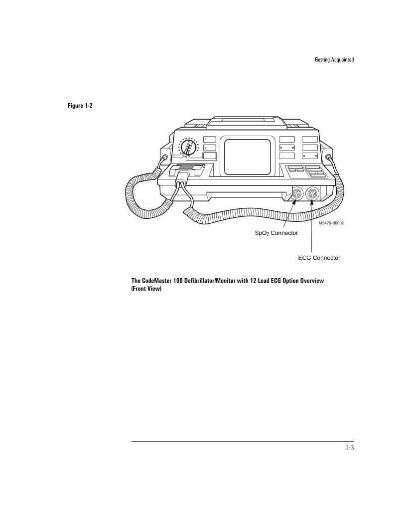
Figure 1-2
The CodeMaster 100 Defibrillator/Monitor with 12-Lead ECG Option Overview (Front View) 1-2
SpO2 Connector
ECG Connector
M2475-B0002

*HWWLQJ�$FTXDLQWHGOperating Controls and Indicators
1-4
1Operating Controls and Indicators
This topic provides figures and tables which detail the controls and indicators on the HP CodeMaster 100.
Defibrillator Operating Controls
The defibrillating operating controls on the HP CodeMaster 100 include Energy Select, Charge, Sync, and Shock. See Figures 1-3 and 1-4.
Figure 1-3
Defibrillator Operating Controls (1 of 2) 1-3
MONITOR RECORDER
Load Select
ECG Size
HR Alarm
Charge
DEFIBRILLATORENERGY SELECT
Sync
Analyze
Advisory On
Record
Mark
ReviewMonitor On
Shock
ShockCharge
Charge
M2475-B0003
Sync

*HWWLQJ�$FTXDLQWHGOperating Controls and Indicators
1-5
Figure 1-4
Defibrillator Operating Controls (2 of 2) 1-4
Charge
DEFIBRILLATORENERGY SELECT
Sync
Advisory On
Monitor On
M2475-B0006
Energy SelectControl

*HWWLQJ�$FTXDLQWHGOperating Controls and Indicators
1-6
Control/Button Function
Energy Select The Energy Select or Power Control turns the CodeMaster 100 power on and off. This control also selects the energy level (Joules) for delivering a shock.
Charge The Charge button charges the defibrillator to the energy level set on the Energy Select
control. Charge buttons are located on the front panel of the CodeMaster 100 and on the apex paddle.
Sync The Sync button changes the operating mode between immediate shock (asynchronous) mode and synchronized with next R-wave shock (Sync) mode. Note that the default is asynchronous mode.
Shock The orange Shock buttons, located on both paddles, administer a shock when pressed simultaneously.
Refer to Chapter 3, “Defibrillating” for more information.

*HWWLQJ�$FTXDLQWHGOperating Controls and Indicators
1-7
Monitor Operating Controls
This section details the operating controls on the HP CodeMaster 100 that enable you to monitor a patient. Refer to Figure 1-5. Refer to Chapter 5, “Monitoring” for more information about patient monitoring.
Figure 1-5
Monitor Operating Controls 1-5
ModeStartStop
Output
RateSpO2Alarm
ECG Input
Pacer On
MONITOR
Lead Select
ECG Size
HR Alarm
S 456

*HWWLQJ�$FTXDLQWHGOperating Controls and Indicators
1-8
Control/Button Function
Lead Select Selects an ECG source to monitor.
ECG Size Changes the displayed ECG size.
HR Alarm Controls heart rate alarms.
Controls the volume of the QRS beeper.
ECG Output connector Located on the right side of the unit - providesanalog 1V/mV output for external monitoring
456

*HWWLQJ�$FTXDLQWHGOperating Controls and Indicators
1-9
Recorder Operating Controls
This section details the recorder operating controls associated with the recorder (printer) on the HP CodeMaster 100. Refer to Figure 1-6.
Figure 1-6
Recorder Operating Controls 1-6
Control/Button Function
Record Starts and stops the recorder. Record does not enter an event into the Event Summary record.
Mark Annotates the ECG strip and/or prints an ECG strip. Mark enters the event into the Event Summary record.
Review Prints an Event Summary record.
RECORDER
Record
Mark
Review
M2475-B0005

*HWWLQJ�$FTXDLQWHGOperating Controls and Indicators
1-10
The function of Mark depends on the state of the recorder.
•When the recorder is running, pressing Mark annotates the ECG and enters that event into the Event Summary record.
•If the recorder is not running and the unit is configured to do so, pressing the Mark key prints an ECG strip and enters the event into the Event Sum-mary.
This annotation can be configured to print on the ECG strip immediately when Mark is pressed or after a 6 second delay.
Refer to Chapter 2, “Setup and Configuration” to configure the HP CodeMaster 100 for recording when Mark is pressed.
When you press Review to print an Event Summary record, the message “ES” is printed at the top of the ECG strip. To print an Event Summary record after starting the recorder, first press Record to stop the recorder, then press Review. See “Printing the Event Summary Record” on page 5-12 for more information.

*HWWLQJ�$FTXDLQWHGOperating Controls and Indicators
1-11
Pacer Operating Controls
This section details the pacer operating controls associated with pacing. Refer to Figure 1-7.
Figure 1-7
Pacer Operating Controls 1-7
ModeStartStop
Output
Rate
SpO2 ECG Input
Pacer On
M2475-B0005
*HWWLQJ�$FTXDLQWHGOperating Controls and Indicators
1-12
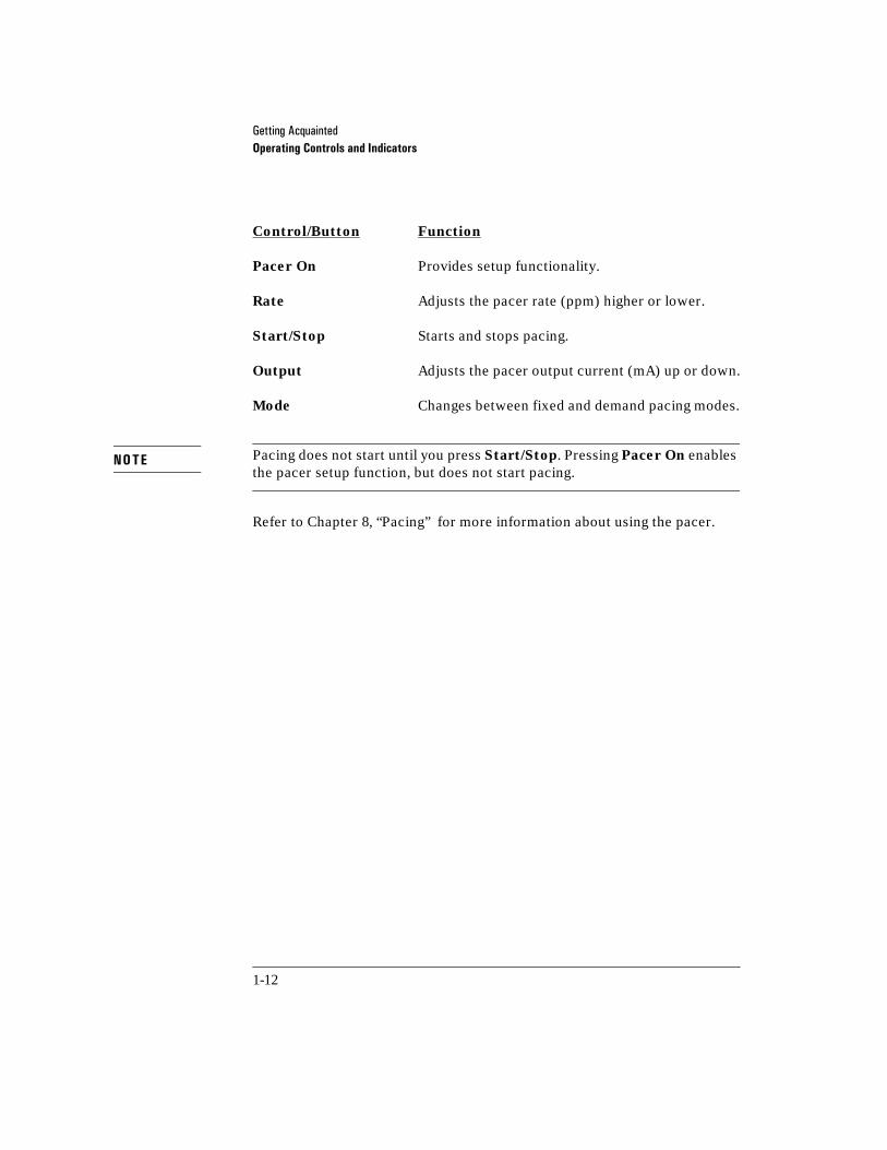
Control/Button Function
Pacer On Provides setup functionality.
Rate Adjusts the pacer rate (ppm) higher or lower.
Start/Stop Starts and stops pacing.
Output Adjusts the pacer output current (mA) up or down.
Mode Changes between fixed and demand pacing modes.
Pacing does not start until you press Start/Stop. Pressing Pacer On enables the pacer setup function, but does not start pacing.
Refer to Chapter 8, “Pacing” for more information about using the pacer.
NOTE

*HWWLQJ�$FTXDLQWHGOperating Controls and Indicators
1-13
SpO2 Operating Controls
This topic details the SpO2 operating controls associated with the SpO2 feature on the HP CodeMaster 100. Refer to Figure 1-8.
Figure 1-8
SpO2 Operating Controls 1-8
SpO2On/Off
SpO2Alarm
SpO2 ECG Input
QRS
M2475-B0005
Sp02 Connector

*HWWLQJ�$FTXDLQWHGOperating Controls and Indicators
1-14
SpO2 Operating Controls
Control/Button Function
SpO2 On/Off �Starts and stops the pulse oximeter�
SpO2 Alarm Controls SpO2 alarms�
SpO2 Connector SpO2 sensors and adapter cables plug into the SpO2 input connector.
Chapter 9, “SpO2 Monitoring” contains further information about using the pulse oximeter.

*HWWLQJ�$FTXDLQWHGOperating Controls and Indicators
1-15
Advisory Mode Operating Controls (Optional)
This section details the operating controls for the HP CodeMaster 100 in Advisory Mode. Figure 1-9 illustrates the placement of the controls.
Figure 1-9
Advisory Mode Operating Controls 1-9
Control/Button Function
Advisory On Places the CodeMaster 100 in advisory mode.
Analyze Starts automatic analysis of ECG waveforms�
Charge
DEFIBRILLATORENERGY SELECT
Sync
Analyze
Advisory On
Monitor On
Off (Standby)
Energy Select
Analyze

*HWWLQJ�$FTXDLQWHGOperating Controls and Indicators
1-16
12-Lead Operating Controls
This section provides an overview of the 12-Lead portion of the CodeMaster 100. Figure 1-10 shows the keypad and operator buttons that you use to setup, acquire, and transmit patient data. Refer to Chapter 6, “Using the 12-Lead Option” for more information.

*HWWLQJ�$FTXDLQWHGOperating Controls and Indicators
1-17
Figure 1-10
12-Lead Keyboard and Display 1-10
ID
12-Lead
Send
F5F4F3F2F1
Q W E R T Y U I O P 7 =
4 :
1 ’
0 )
8 -
5 %
2 .
Filter
9 (
6 +
3 ;
Copy
A S < D > F ? G / H " J ’ K L
Shift
Alt
Z & X * C @ V ^ B # N ! M ~
Stop
Menu
Shift
M2475-B0004
*HWWLQJ�$FTXDLQWHGOperating Controls and Indicators
1-18
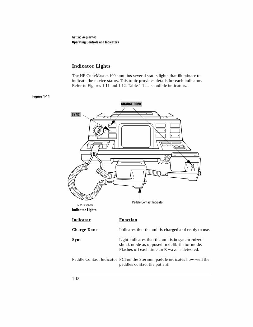
Indicator Lights
The HP CodeMaster 100 contains several status lights that illuminate to indicate the device status. This topic provides details for each indicator. Refer to Figures 1-11 and 1-12. Table 1-1 lists audible indicators.
Figure 1-11
Indicator Lights 1-11
Indicator Function
Charge Done Indicates that the unit is charged and ready to use.
Sync Light indicates that the unit is in synchronized shock mode as opposed to defibrillator mode. Flashes off each time an R-wave is detected.
Paddle Contact Indicator PCI on the Sternum paddle indicates how well the paddles contact the patient.
M2475-B00033DGGOH�&RQWDFW�,QGLFDWRU
CHARGE DONE
SYNC

*HWWLQJ�$FTXDLQWHGOperating Controls and Indicators
1-19
Figure 1-12
Battery Indicator Lights 1-12
Indicator Function
Battery Capacity Gauge After you press the button below the indicator, the battery capacity gauge indicates the remaining battery charge.
Quick-change battery
Battery capacity gauge
M2475-B0007

*HWWLQJ�$FTXDLQWHGOperating Controls and Indicators
1-20
Table 1-1 Audible Indicators
Indicator Description
&KDUJH�'RQH�WRQH 6RXQGV�ZKHQ�WKH�LQVWUXPHQW�LV�FKDUJHG�DQG�UHDG\�WR�GHOLYHU�D�VKRFN��It can be disabled in setup�
$XWR�GLVDUP�WRQH 6RXQGV�GXULQJ�WKH�ODVW�WHQ�VHFRQGV�RI�WKH�&KDUJH�'RQH�WRQH��%HHSV�LQWHUPLWWHQWO\�XQWLO�GLVDUPHG�
456�EHHSHU 6RXQGV�ZKHQHYHU�DQ�5�ZDYH�LV�GHWHFWHG��9ROXPH�FRQWUROOHG�E\� �ORFDWHG�RQ�WKH�ORZHU�ULJKW�NH\SDQHO�
&57�6FUHHQ�DOHUWV 7KUHH�EHHSV�HDFK�WLPH�D�PHVVDJH�DSSHDUV�RQ�WKH�VFUHHQ��It can be disabled in setup�
+5�DODUPV 6RXQGV�LI�WKH�KHDUW�UDWH�LV�DERYH�WKH�KLJKHU�DODUP�OLPLW�RU�EHORZ�WKH�ORZHU�DODUP�OLPLW�
6KXWGRZQ�ZDUQLQJ $OWHUQDWLQJ�SLWFK�VRXQGV�IRU����VHFRQGV�ZKHQ�WKH�V\VWHP�LV�DERXW�WR�WXUQ�RII��$Q�DOHUW�WR�UHSODFH�WKH�EDWWHU\�
&KHFN�EDWWHU\�DOHUW 6HW�RI���EHHSV�ZLWK�D�PHVVDJH�CHECK BATTERY�RQ�WKH�PRQLWRU�LQGLFDWLQJ�WKDW�WKH�EDWWHU\�LV�IDXOW\�RU�QRW�ODWFKHG�VHFXUHO\�
/RZ�EDWWHU\�DOHUW &RQWLQXRXV�EHHSV�ZLWK�D�PHVVDJH�LOW BATTERY�RQ�WKH�PRQLWRU�LQGLFDWLQJ�WKDW�WKH�EDWWHU\�QHHGV�WR�EH�UHSODFHG�
456

*HWWLQJ�$FTXDLQWHGSafety Considerations
1-21
1Safety Considerations
The HP CodeMaster 100 stores high voltage energy and is capable of delivering up to 360 joules of DC energy to a 50 ohm impedance.
To remove power from the instrument, you must turn the Energy Select
control to Off.
Disarming the Defibrillator
There are three ways to disarm a charged instrument:
•Turning the Energy Select control from an energy level setting to the Monitor On position.
•Placing the paddles in their holders and depressing both shock ( ) buttons simultaneously.
•Waiting for the instrument to automatically disarm. The unit disarms auto-matically after it has been left charged for 60 seconds in the Manual mode and after 30 seconds in the Advisory Mode.
Do not leave the instrument turned on when it is not in use.
Do not discharge the defibrillator with the paddles shorted together which can cause burning and pitting of the metal paddle contacts.
Disconnect any other medical electronic equipment from the patient during defibrillation unless labeled as defibrillator protected ( ) ( ).
CAUTION
*HWWLQJ�$FTXDLQWHGSafety Considerations
1-22
Avoid open paddle discharges. Dangerous high voltage exists on the paddles when the defibrillator is discharged. Contact with this high voltage could cause death or serious injury.
Avoid touching any metal surfaces on the instrument during discharge.
Avoid connecting the patient to several devices at once, because leakage current limits may be exceeded.
Never touch the bed, gurney, the patient, or any equipment connected to the patient during defibrillation.
Keep the HP CodeMaster 100 and the immediate area clean and dry at all times to avoid creating potentially dangerous electrical paths.
Never open the instrument case. Dangerous high voltages can be exposed. Only qualified service personnel can service the instrument.
Do not use the defibrillator in a flammable or oxygen-rich atmosphere. This will cause an explosion hazard.
Do not rely entirely upon heart rate alarms. Rate meters on pacemaker patients can continue to count the pacemaker rates during cardiac arrest or some arrhythmias. Keep pacemaker patients under close observation.
Avoid moving a charged defibrillator. If you drop the unit, it may discharge.
WARNING
*HWWLQJ�$FTXDLQWHGBattery Operation
1-23
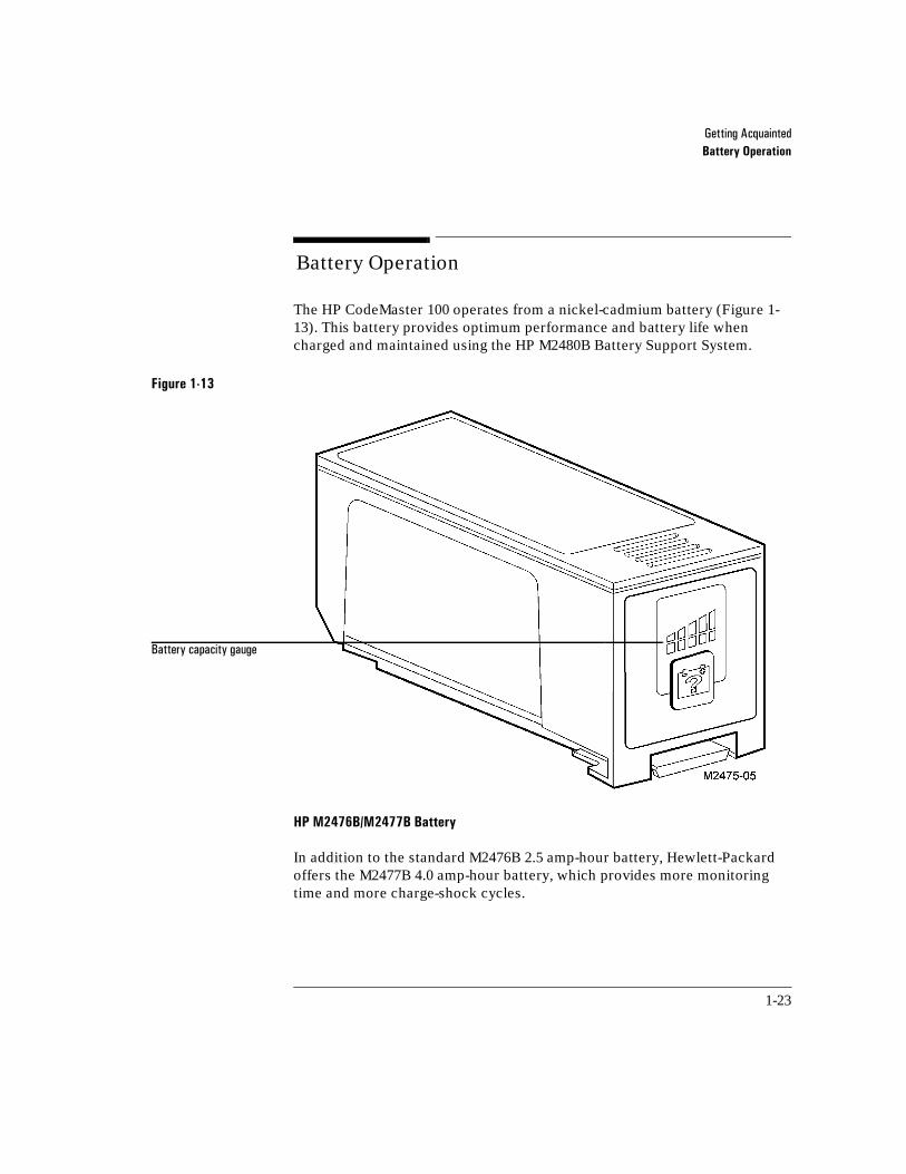
1Battery Operation
The HP CodeMaster 100 operates from a nickel-cadmium battery (Figure 1-13). This battery provides optimum performance and battery life when charged and maintained using the HP M2480B Battery Support System.
Figure 1-13
HP M2476B/M2477B Battery 1-13
In addition to the standard M2476B 2.5 amp-hour battery, Hewlett-Packard offers the M2477B 4.0 amp-hour battery, which provides more monitoring time and more charge-shock cycles.
%DWWHU\�FDSDFLW\�JDXJH

*HWWLQJ�$FTXDLQWHGBattery Operation
1-24
Supported Battery Replacements
Replace the battery only with one of the batteries listed in Table 1-2.
Testing a Battery
To test the remaining charge in the battery, press the button below the battery capacity gauge. Lights within the battery capacity gauge show the amount of charge left in the battery. Each light represents 20% of the battery capacity. When only one light is on, the battery has between zero and 20% capacity remaining. When all lights are on, the battery has between 80 and 100% capacity remaining.
Recharging a Battery
To recharge the battery, remove it from the defibrillator and insert it into the Battery Support System. To charge the battery, see “Charging the Battery” on page 13-14.
The battery support system can recharge two batteries simultaneously.
Test the capacity of a new battery or one that has been stored more than one month as described in “Battery Capacity Test” in Chapter 13, “Maintenance”.
Continuous recording reduces the monitoring time available.
Table 1-2 Battery Specifications
Battery360 Joules Charge-Shock Cycles
Monitoring TimeApproximate Recharging Time
0����%�����DPS�KRXU�EDWWHU\ �� ��KRXUV� ��KRXUV�
0����%�����DPS�KRXU�EDWWHU\ �� ��KRXUV ��KRXUV�
NOTE

*HWWLQJ�$FTXDLQWHGBattery Operation
1-25
When the LOW BATTERY message is displayed on the monitor, replace the battery pack with a charged battery pack.
From the time the LOW BATTERY message appears until the battery is fully depleted and the instrument shuts down, there is approximately thirty minutes of monitoring and five 360 joule charge-shock cycles.
If the battery is defective, there may be significantly less monitoring time or charge capacity after the LOW BATTERY message appears than if the battery is merely depleted. Recording during this time will also impact monitoring time and the number of charge shock cycles remaining.
CAUTION

*HWWLQJ�$FTXDLQWHGBattery Operation
1-26

2-1
2Setup and Configuration
This chapter provides steps for setting up and configuring the HP CodeMaster 100. Your HP CodeMaster 100 ships protected within a carry bag. For instructions on s how to attach the side-pouches and shoulder strap, refer to M3710A Carry Bag Instructions for Use (M2475-94000).
2Setting Up the CodeMaster 100
The HP CodeMaster 100 is ready for operation after you perform the following tasks:
• Insert the Battery.
• Load Recorder Paper.
• Seat and lock the paddles or defib electrode cable.
• Connect the patient cable.
• Select configuration settings for both the CodeMaster 100 and the 12-Lead option including such parameters as;
-date and time
-12-Lead keyboard to uppercase or lowercase mode
-12-Lead telephone directory for transmission
-12-Lead acquisition information
-12-Lead report content information
-12-Lead location and ID codes

6HWXS�DQG�&RQILJXUDWLRQSetting Up the CodeMaster 100
2-2
Inserting the Battery
Before using the battery supplied with your HP CodeMaster 100, make sure it is fully charged and functional. Remove the battery from the defibrillator by pinching the latch and pulling the battery out and up.
Perform the “Battery Capacity Test” on page 13-15 to charge and test the battery.
Insert a fully charged and tested battery into the CodeMaster 100 (Figure 2-1). Insert the battery into the compartment with the connector to the inside. Slide the battery into the compartment until it latches.
Figure 2-1
Loading the Battery into the CodeMaster 100 2-1
Quick-change battery latch
Battery capacity gauge
M2475-B0007

6HWXS�DQG�&RQILJXUDWLRQSetting Up the CodeMaster 100
2-3
If the battery is not properly seated in the battery compartment of the CodeMaster 100, the instrument will display the warning message CHECK BATTERY accompanied by an audible warning when you power on the instrument.
Loading the Recorder Paper
The HP CodeMaster 100 recorder uses 50mm wide, thermal recorder paper (HP 40457C/D). To load the paper, refer to “Changing the Recorder Paper” on page 13-7.
Connecting the Paddles or Multifunction Defib Electrodes and Patient Cables
The defibrillator has a paddles/electrode adapter cable for attaching external paddles, internal paddles, or multifunction defib electrodes. It also has an ECG Input connector for attaching ECG leads.
NOTE
6HWXS�DQG�&RQILJXUDWLRQSetting Up the CodeMaster 100
2-4
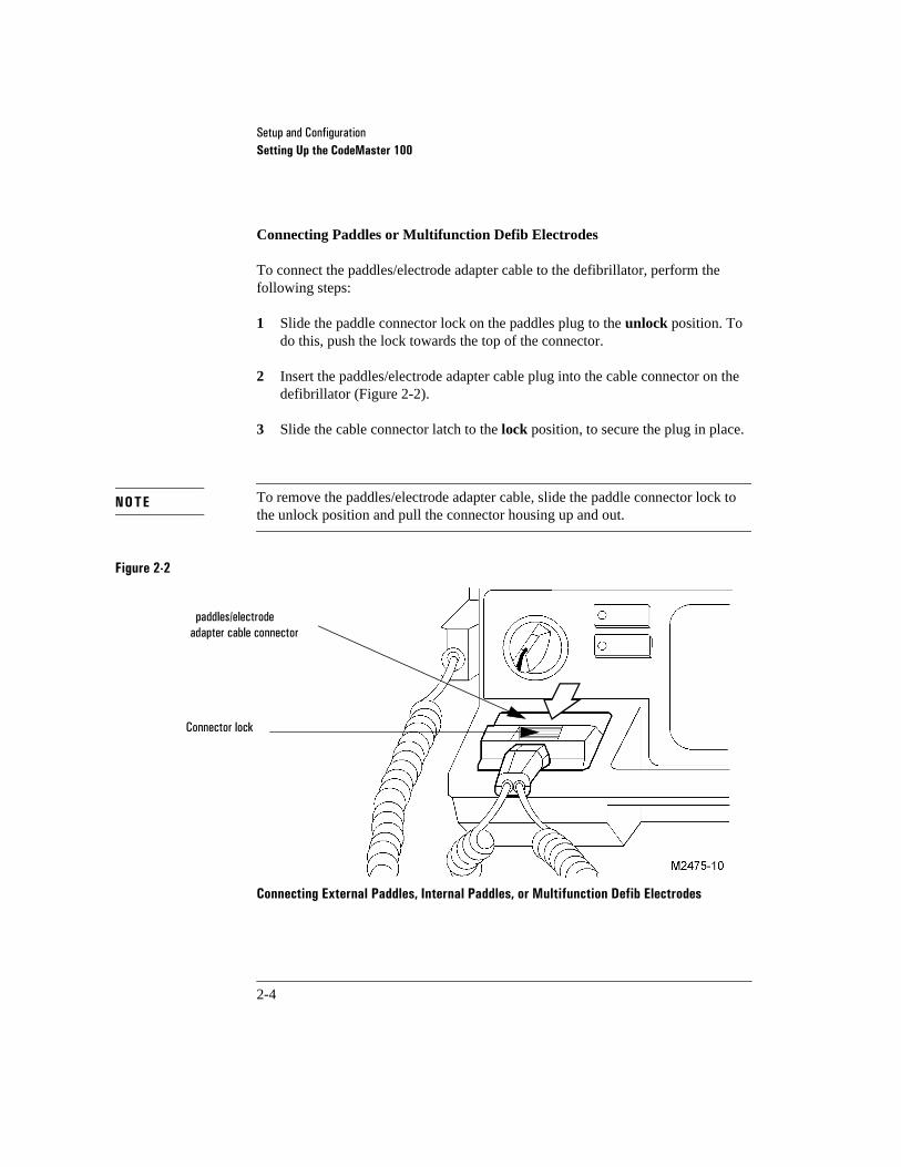
Connecting Paddles or Multifunction Defib Electrodes
To connect the paddles/electrode adapter cable to the defibrillator, perform the following steps:
1 Slide the paddle connector lock on the paddles plug to the unlock position. To do this, push the lock towards the top of the connector.
2 Insert the paddles/electrode adapter cable plug into the cable connector on the defibrillator (Figure 2-2).
3 Slide the cable connector latch to the lock position, to secure the plug in place.
To remove the paddles/electrode adapter cable, slide the paddle connector lock to the unlock position and pull the connector housing up and out.
Figure 2-2
Connecting External Paddles, Internal Paddles, or Multifunction Defib Electrodes 2-2
NOTE
SDGGOHV�HOHFWURGHDGDSWHU�FDEOH�FRQQHFWRU
&RQQHFWRU�ORFN

6HWXS�DQG�&RQILJXUDWLRQSetting Up the CodeMaster 100
2-5
ECG Input Connector
The HP patient cable supplied with this device, or an HP approved substitute patient cable, is an integral part of the defibrillator/monitor safety features. Using any other patient cable may compromise defibrillation protection as well as performance. Only qualified personnel may service the device.
The ECG Input connector on the defibrillator is a 12-pin connector.
Connecting the Patient Cable The 3-wire, 5-wire, and 10-wire patient cables connect to the ECG Input connector located on the front right side of the defibrillator, below the QRS volume and pacer controls. The patient cable plug has 12-pins. To install the patient cable (Figure 2-3):
1 Align the keyed cable plug with the slot in the ECG Input connector.
2 Push the cable plug firmly into the ECG Input connector.
If Leads is selected as the ECG source, the message LEADS OFF will appear on the monitor display if the patient electrode becomes disconnected. A dashed line appears on the display in place of an ECG trace.
WARNING
NOTE

6HWXS�DQG�&RQILJXUDWLRQSetting Up the CodeMaster 100
2-6
Figure 2-3
Connecting a Patient Cable 2-3
(&*�LQSXW�FRQQHFWRU�ZLWK�NH\�VORWV�
�
.H\HG�SOXJ�RI�SDWLHQW�FDEOH
...

6HWXS�DQG�&RQILJXUDWLRQConfiguring the CodeMaster 100 and 12-Lead ECG Option
2-7
2Configuring the CodeMaster 100 and 12-Lead ECG Option
This section provides instructions for configuring the CodeMaster 100 and 12-Lead ECG option.
To configure general items such as the date and time, as well as all defibrillating and monitoring settings, use the Setup Menus accessible through the front panel keys and front display. Table 2-1 and Table 2-2 list the selections available on the Setup Menus.
To configure 12-Lead ECG and transmission settings, use the Configuration Menu accessible from the top keypad and upper display. Table 2-3 lists the selections available on the Configuration Menu.
A small internal battery provides back up power to store the configuration information. Under normal conditions, the backup battery may last for five years. Extreme conditions (such as prolonged high temperatures) may reduce the life of the backup battery.
After running the “Delivered Energy and Shock Button Functional Test” on page 13-3, you may see a CHECK SETUP message on the screen. This message appears when the backup battery has approximately 90 days of life remaining.
When you see the CHECK SETUP message on the screen, call service to replace the backup battery.
If you do not replace the backup battery, the SETUP LOST message appears on the screen after the internal battery depletes, and you may have to reconfigure the instrument.
CAUTION
6HWXS�DQG�&RQILJXUDWLRQConfiguring the CodeMaster 100
2-8
2Configuring the CodeMaster 100
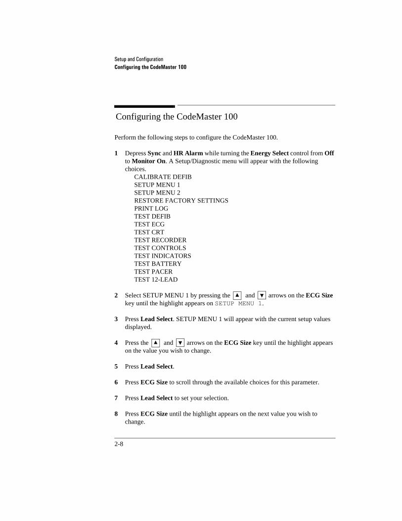
Perform the following steps to configure the CodeMaster 100.
1 Depress Sync and HR Alarm while turning the Energy Select control from Off to Monitor On. A Setup/Diagnostic menu will appear with the following choices.
CALIBRATE DEFIBSETUP MENU 1 SETUP MENU 2 RESTORE FACTORY SETTINGS PRINT LOG TEST DEFIB TEST ECG TEST CRT TEST RECORDER TEST CONTROLS TEST INDICATORS TEST BATTERY TEST PACERTEST 12-LEAD
2 Select SETUP MENU 1 by pressing the and arrows on the ECG Size key until the highlight appears on SETUP MENU 1.
3 Press Lead Select. SETUP MENU 1 will appear with the current setup values displayed.
4 Press the and arrows on the ECG Size key until the highlight appears on the value you wish to change.
5 Press Lead Select.
6 Press ECG Size to scroll through the available choices for this parameter.
7 Press Lead Select to set your selection.
8 Press ECG Size until the highlight appears on the next value you wish to change.
6HWXS�DQG�&RQILJXUDWLRQConfiguring the CodeMaster 100
2-9
9 Repeat steps 5 through 8 until you are finished configuring the settings in Setup Menu 1.
10 Depress both sides of the ECG Size key simultaneously to return to the Setup/Diagnostic Menu.
11 To change settings in Setup Menu 2, select SETUP MENU 2 from the Setup/Diagnostic Menu and repeat the above steps.
12 Turn the Energy Select control to Off to exit Setup/Diagnostic mode.
Restoring Factory Settings
You can use the factory setting for most values by selecting RESTORE FACTORY SETTINGS from the Setup/Diagnostic Menu. Highlighting and selecting this setting does NOT bring up an additional menu. Selecting this line will undo user configured parameters and restore factory defaults. This process restores factory settings on the defibrillator/monitor and not on the 12-Lead option.
HP recommends that you not use the 12-Lead option to acquire, view, store, print or transmit when in Diagnostic Mode as the ECG may be lost and the 12-Lead capability may be reset.
WARNING

6HWXS�DQG�&RQILJXUDWLRQConfiguring the CodeMaster 100
2-10
To set the time on the CodeMaster 100:
1 Press Sync and HR Alarm at the same time while turning the Energy Select control from Off to Monitor On.
2 Press ECG Size once to highlight SETUP MENU 1.
3 Press Lead Select. SETUP MENU 1 appears.
4 Press ECG Size seven times to highlight Time.
5 Press Lead Select.
6 Press ECG Size until the hours setting contains the correct time.
7 Press Lead Select.
8 Press ECG Size to select minutes.
9 Press Lead Select.
10 Press ECG Size until the minutes setting contains the correct time.
11 Press Lead Select.
12 Depress both sides of the ECG Size key simultaneously to return to the Setup/Diagnostic Menu.
13 Turn the Energy Select control to Off.
Example
6HWXS�DQG�&RQILJXUDWLRQConfiguring the CodeMaster 100
2-11
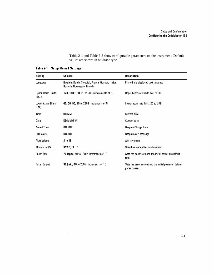
Table 2-1 and Table 2-2 show configurable parameters on the instrument. Default values are shown in boldface type.
Table 2-1 Setup Menu 1 Settings
Setting Choices Description
/DQJXDJH English��'XWFK��6ZHGLVK��)UHQFK��*HUPDQ��,WDOLDQ��6SDQLVK��1RUZHJLDQ��)LQQLVK
3ULQWHG�DQG�GLVSOD\HG�WH[W�ODQJXDJH�
8SSHU�$ODUP�/LPLWV��8$/�
120, 140, 160�����WR�����LQ�LQFUHPHQWV�RI�� 8SSHU�KHDUW�UDWH�OLPLWV�/$/�WR�����
/RZHU�$ODUP�/LPLWV��/$/�
40, 60, 90�����WR�����LQ�LQFUHPHQWV�RI�� /RZHU�KHDUW�UDWH�OLPLWV����WR�8$/�
7LPH ++�00� &XUUHQW�WLPH�
'DWH ''�000�<< &XUUHQW�GDWH�
$UPHG�7RQH ON��2)) %HHS�RQ�&KDUJH�GRQH�
&57�$OHUWV ON��2))� %HHS�RQ�DOHUW�PHVVDJH�
$OHUW�9ROXPH ��WR�15 $OHUWV�YROXPH�
0RGH�DIWHU�&9� SYNC��'(),% 6SHFLILHV�PRGH�DIWHU�FDUGLRYHUVLRQ�
3DFHU�5DWH 70 (ppm)�����WR�����LQ�LQFUHPHQWV�RI��� 6HWV�WKH�SDFHU�UDWH�DQG�WKH�LQLWLDO�SRZHU�RQ�GHIDXOW�UDWH��
3DFHU�2XWSXW 30 (mA)�����WR�����LQ�LQFUHPHQWV�RI��� 6HWV�WKH�SDFHU�FXUUHQW�DQG�WKH�LQLWLDO�SRZHU�RQ�GHIDXOW�SDFHU�FXUUHQW��
6HWXS�DQG�&RQILJXUDWLRQConfiguring the CodeMaster 100
2-12
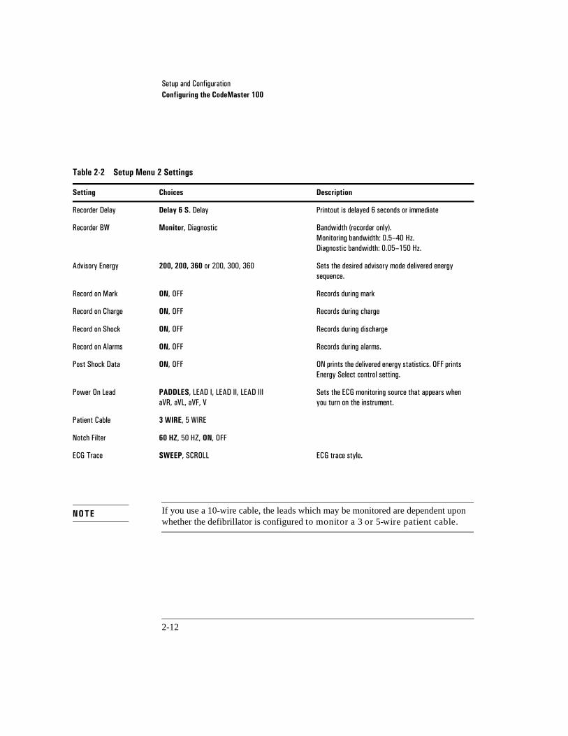
If you use a 10-wire cable, the leads which may be monitored are dependent upon whether the defibrillator is configured to monitor a 3 or 5-wire patient cable.
Table 2-2 Setup Menu 2 Settings
Setting Choices Description
5HFRUGHU�'HOD\ Delay 6 S.�'HOD\ 3ULQWRXW�LV�GHOD\HG���VHFRQGV�RU�LPPHGLDWH�
5HFRUGHU�%: Monitor��'LDJQRVWLF %DQGZLGWK��UHFRUGHU�RQO\���0RQLWRULQJ�EDQGZLGWK�����²���+]��'LDJQRVWLF�EDQGZLGWK������²����+]�
$GYLVRU\�(QHUJ\ 200, 200, 360�RU�������������� 6HWV�WKH�GHVLUHG�DGYLVRU\�PRGH�GHOLYHUHG�HQHUJ\�VHTXHQFH�
5HFRUG�RQ�0DUN ON��2)) 5HFRUGV�GXULQJ�PDUN�
5HFRUG�RQ�&KDUJH ON��2)) 5HFRUGV�GXULQJ�FKDUJH�
5HFRUG�RQ�6KRFN ON��2)) 5HFRUGV�GXULQJ�GLVFKDUJH�
5HFRUG�RQ�$ODUPV ON��2)) 5HFRUGV�GXULQJ�DODUPV��
3RVW�6KRFN�'DWD ON��2)) 21�SULQWV�WKH�GHOLYHUHG�HQHUJ\�VWDWLVWLFV��2))�SULQWV�(QHUJ\�6HOHFW�FRQWURO�VHWWLQJ��
3RZHU�2Q�/HDG PADDLES��/($'�,��/($'�,,��/($'�,,,D95��D9/��D9)��9
6HWV�WKH�(&*�PRQLWRULQJ�VRXUFH�WKDW�DSSHDUV�ZKHQ�\RX�WXUQ�RQ�WKH�LQVWUXPHQW��
3DWLHQW�&DEOH 3 WIRE����:,5(�
1RWFK�)LOWHU 60 HZ�����+=��ON��2))�
(&*�7UDFH SWEEP��6&52// (&*�WUDFH�VW\OH�
NOTE

6HWXS�DQG�&RQILJXUDWLRQConfiguring the 12-Lead Option
2-13
2Configuring the 12-Lead Option
This topic provides procedures for configuring the 12-Lead option. Table 2-3 lists the selections available on the Configuration Menu.
Table 2-3 12-Lead Configuration Menu Settings
Menu Selection Function
6HWXS�,'�(QWU\ ,GHQWLI\�ZKLFK�SDWLHQW�LQIRUPDWLRQ�ILHOGV�ZLOO�EH�XVHG��'HILQH�WKH�WH[W�FRQWDLQHG�LQ�XVHU�GHILQHG�ILHOGV�
6HWXS����/HDG�6HWWLQJV ,GHQWLI\�(&*�OHDG�IRUPDW�DQG�QRPHQFODWXUH�XVHG�RQ�SULQWHG����/HDG�(&*�UHSRUWV
6HWXS�(&*�)LOWHUV ,GHQWLI\�ZKLFK�ILOWHUV�ZLOO�EH�XVHG�WR�FODULI\�(&*V�LQ�QRLV\�HQYLURQPHQWV
6HWXS�0LVFHOODQHRXV 6HW�WKH�,QVWLWXWLRQ�ODEHO��VHW�W\SH�RI�LQWHUSUHWDWLRQ��VHW�WKH�QXPEHU�RI�(&*�FRSLHV�SULQWHG��VHW����/HDG�NH\SDG�WR�XSSHU�RU�ORZHU�FDVH��VHW����/HDG�ORFDWLRQ�FRGH�DQG�,'�
6HWXS�7UDQVPLVVLRQ 'HILQH�PRGHP�LQLWLDOL]DWLRQ�VWULQJV��FHOOXODU�GLDOLQJ�SUHIL[�
6HWXS�*DWHZD\ 'HILQH�WHOHSKRQH�QXPEHU�IRU�JDWHZD\�LI�D�JDWHZD\�LV�XVHG�
6HWXS�7HOHSKRQH�'LUHFWRU\ 'HILQH�QDPHV��WHOHSKRQH�QXPEHUV��DQG�W\SH�RI�HTXLSPHQW�XVHG�DW�UHFHLYLQJ�VLWHV�
6HWXS�$XWRPDWHG�2SHUDWLRQV (QDEOH�DXWRPDWLF�WUDQVPLVVLRQ�RI�(&*V�LI�GHVLUHG�

6HWXS�DQG�&RQILJXUDWLRQConfiguring the 12-Lead Option
2-14
Navigating the Configuration Menus
When you need to edit the 12-Lead configuration, use the following techniques:
• To enter the 12-Lead configuration menu, press the Menu key on the keyboard.
• To select from a menu, press to move the cursor down, or press to move the cursor up until the desired menu line is highlighted, then press F3 to display the selected item.
• To select a field on a data entry screen, press or to move the cursor down, or press or to move the cursor up until the desired entry line is high-lighted. To save the settings, exit the Configuration menu.
• To change a field, select F3 to step through the choices available.
• To exit the Configuration menu and save your configuration data, press F5.
Adjusting Display Screen Contrast
Press Shift with the or key to lighten or darken the contrast on the 12-Lead display.
6HWXS�DQG�&RQILJXUDWLRQConfiguring the 12-Lead Option
2-15
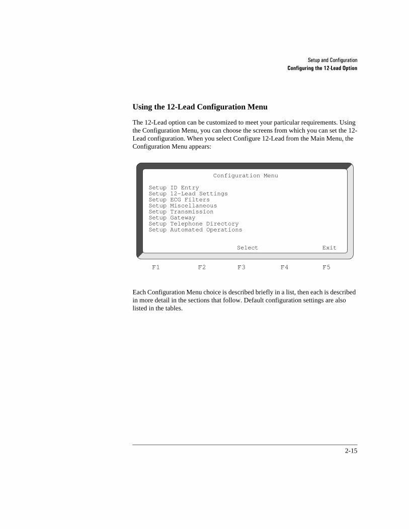
Using the 12-Lead Configuration Menu
The 12-Lead option can be customized to meet your particular requirements. Using the Configuration Menu, you can choose the screens from which you can set the 12-Lead configuration. When you select Configure 12-Lead from the Main Menu, the Configuration Menu appears:
Each Configuration Menu choice is described briefly in a list, then each is described in more detail in the sections that follow. Default configuration settings are also listed in the tables.
Configuration Menu
Setup ID EntrySetup 12-Lead SettingsSetup ECG FiltersSetup MiscellaneousSetup TransmissionSetup GatewaySetup Telephone DirectorySetup Automated Operations
Select Exit
F1 F2 F3 F4 F5
6HWXS�DQG�&RQILJXUDWLRQConfiguring the 12-Lead Option
2-16
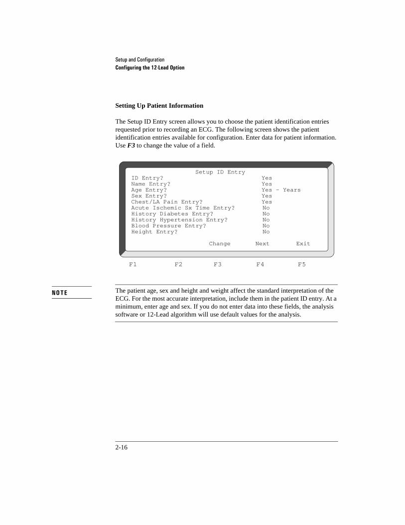
Setting Up Patient Information
The Setup ID Entry screen allows you to choose the patient identification entries requested prior to recording an ECG. The following screen shows the patient identification entries available for configuration. Enter data for patient information. Use F3 to change the value of a field.
The patient age, sex and height and weight affect the standard interpretation of the ECG. For the most accurate interpretation, include them in the patient ID entry. At a minimum, enter age and sex. If you do not enter data into these fields, the analysis software or 12-Lead algorithm will use default values for the analysis.
Setup ID EntryID Entry? YesName Entry? YesAge Entry? Yes - YearsSex Entry? YesChest/LA Pain Entry? YesAcute Ischemic Sx Time Entry? NoHistory Diabetes Entry? NoHistory Hypertension Entry? NoBlood Pressure Entry? NoHeight Entry? No
Change Next Exit
F1 F2 F3 F4 F5
NOTE
6HWXS�DQG�&RQILJXUDWLRQConfiguring the 12-Lead Option
2-17
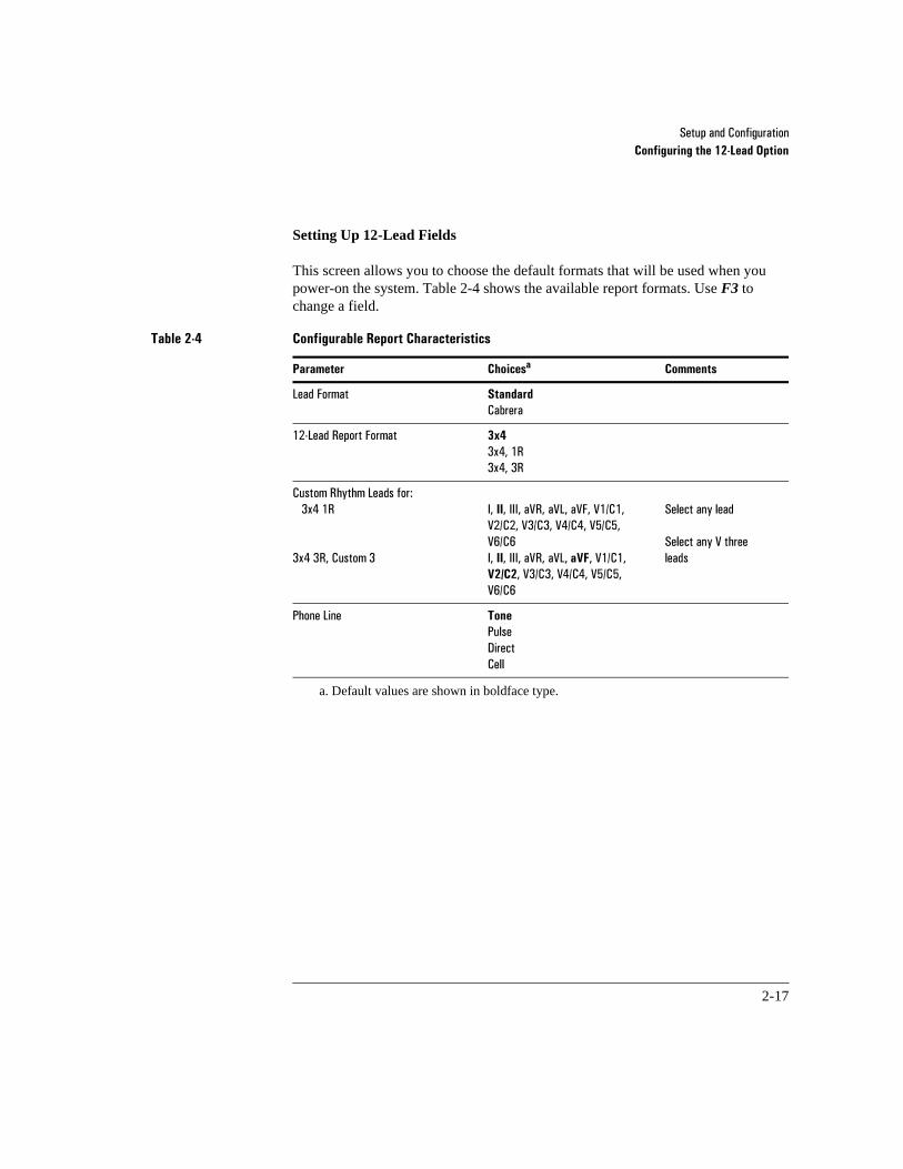
Setting Up 12-Lead Fields
This screen allows you to choose the default formats that will be used when you power-on the system. Table 2-4 shows the available report formats. Use F3 to change a field.
a. Default values are shown in boldface type.
Table 2-4 Configurable Report Characteristics
Parameter Choicesa Comments
/HDG�)RUPDW Standard&DEUHUD
���/HDG�5HSRUW�)RUPDW 3x4�[����5�[����5
&XVWRP�5K\WKP�/HDGV�IRU�����[���5
����[���5��&XVWRP��
,��II��,,,��D95��D9/��D9)��9��&���9��&���9��&���9��&���9��&���9��&�,��II��,,,��D95��D9/��aVF��9��&���V2/C2��9��&���9��&���9��&���9��&�
6HOHFW�DQ\�OHDG
6HOHFW�DQ\�9�WKUHH�OHDGV
3KRQH�/LQH Tone3XOVH'LUHFW&HOO

6HWXS�DQG�&RQILJXUDWLRQConfiguring the 12-Lead Option
2-18
Setup 12-Lead Settings
Lead Format: Standard12-Lead Report Format: 3x4
Custom Rhythm Leads for-3x4 1R: II3x4 3R, Manual 3: II aVF V2
Phone Line: Tone
Change Format Exit
F1 F2 F3 F4 F5

6HWXS�DQG�&RQILJXUDWLRQConfiguring the 12-Lead Option
2-19
Setting Up Filters
From the Configuration Menu, select Setup ECG Filters. The 12-Lead option has been factory-configured with the filter settings which remove the most noise from the ECG. In addition to the default settings, 12-Lead offers a choice of several filter configurations. These filter settings are detailed below and in Table 2-5.
• The 0.5 Hz Baseline Wander filter suppresses the greatest amount of baseline wander.
• The 0.15 Hz Baseline Wander filter provides some baseline wander suppression without distorting the ECG’s ST segment.
• The 0.05 Hz Baseline Wander filter delivers the highest fidelity signal, but pro-vides the least baseline wander suppression.
• The 40 Hz Noise filter offers maximum noise suppression, but reduces the fidelity of the signal.
• The 100 Hz Noise filter provides some noise suppression while offering an accu-rate signal representation.
• The 150 Hz Noise filter delivers the highest fidelity signal, but provides the least high-frequency noise suppression.
Setup ECG Filters
12-Lead Report Filters -Wander Filter: 1.5 HzNoise Filter: 40 Hz
Front Panel Filter Key-Muscle Artifact Filter: Yes40 Hz Noise Filter: Yes0.5 Hz Wander Filter: Yes
Change Value Exit
F1 F2 F3 F4 F5

6HWXS�DQG�&RQILJXUDWLRQConfiguring the 12-Lead Option
2-20
• The Muscle Artifact filter will be enabled when the Filter key is pressed. It removes small-amplitude, high-frequency signals, characteristic of muscle tremor.
When the front panel Filter key is on, the user-configured combination of the Artifact, 0.5 Hz Wander, and 40 Hz Noise filters is enabled and the Filter status message appears in the upper-right corner of the display. Refer to Table 2-5 for information on configuring the Filter key.
a. Default values are shown in boldface font.
NOTE
Table 2-5 Configurable Filters
Parameter Choicesa Comments
:DQGHU�)LOWHU �����+]0.15 Hz����+]
6HOHFW�RQH�EDVHOLQH�ZDQGHU�ILOWHU�IRU�(&*V�
1RLVH�)LOWHU 40 Hz����+]����+]
6HOHFW�RQH�QRLVH�ILOWHU�IRU����/HDG�(&*V�
)URQW�3DQHO Filter�.H\��0XVFOH�$UWLIDFW�ILOWHU������+]�%DVHOLQH�:DQGHU�ILOWHU�����+]�1RLVH�)LOWHU
Yes�RU�1RYes�RU�1RYes�RU�1R
6HOHFW�ZKHWKHU�RU�QRW�WKH�DUWLIDFW��EDVHOLQH�ZDQGHU�DQG�QRLVH�ILOWHUV�DUH�DFWL�YDWHG�E\�WKH�Filter�NH\�
6HWXS�DQG�&RQILJXUDWLRQConfiguring the 12-Lead Option
2-21
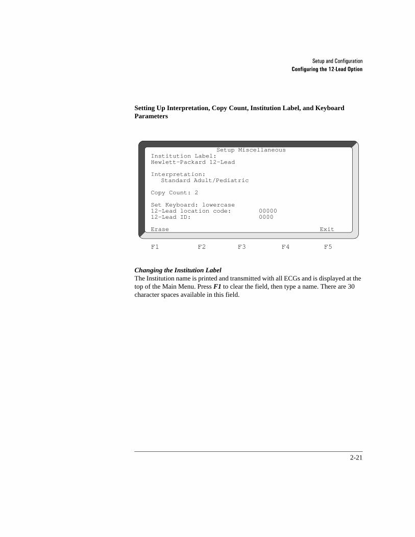
Setting Up Interpretation, Copy Count, Institution Label, and Keyboard Parameters
Changing the Institution Label The Institution name is printed and transmitted with all ECGs and is displayed at the top of the Main Menu. Press F1 to clear the field, then type a name. There are 30 character spaces available in this field.
Setup MiscellaneousInstitution Label:Hewlett-Packard 12-Lead
Interpretation:Standard Adult/Pediatric
Copy Count: 2
Set Keyboard: lowercase12-Lead location code: 0000012-Lead ID: 0000
Erase Exit
F1 F2 F3 F4 F5

6HWXS�DQG�&RQILJXUDWLRQConfiguring the 12-Lead Option
2-22
Setting Interpretation Values Interpretation values determine which analysis is applied to an ECG report. The settings are:
None Selecting None disables printing of all computer generated interpretation of the ECG. The waveform prints along with the following fields: Patient ID, Patient Name, Date and Time
Measurements Only
Selecting this setting provides an additional page containing the basic measurements and all entered ID fields. Basic measurements are defined in Chapter 6, “Using the 12-Lead Option”.
Standard Adult/Pediatric
Selecting this setting prints waveform, patient ID, basic measurements summary, and standard adult or pediatric (depending on age entered) computer generated diagnostic statements.
ACI-TIPI Selecting ACI-TIPI provides waveform, patient ID, basic measurements summary, all available patient demographics and computer calculated probability of acute cardiac ischemia.
TPI Selecting TPI provides waveform, patient ID, basic mea-surements summary, all available patient demographics and predicts patient outcomes (mortality) with and without administering thrombolyties.

6HWXS�DQG�&RQILJXUDWLRQConfiguring the 12-Lead Option
2-23
Setting Copy Count Determines how many copies are printed when you press the Copy key. You can enter a value from 1-4. The default value is 2.
Setting Keyboard Values Keyboard mode determines whether characters will be entered in uppercase or lowercase. Press F3 to change from lowercase to UPPERCASE and vice versa. The keyboard is initially set to lowercase. Use the shift key to enter the opposite case.
Setting 12-Lead Location Code The 12-Lead location code identifies a specific department or EMS Service that acquired the ECG. The number prints at the bottom of the report. If set to zero (default), this field will be suppressed from the printed report. This parameter can be any five digit numeric code.
Setting 12-Lead ID The 12-Lead ID code identifies the particular CodeMaster 100 unit that was used to acquire the ECG. The number prints at the bottom of the report. If set to zero (default), this field will be omitted from the printed report. This parameter can be any four digit numeric code.

6HWXS�DQG�&RQILJXUDWLRQConfiguring the 12-Lead Option
2-24
Setup Transmission
This menu allows the configuration of both the internal and an external modem. Note that your CodeMaster 100 with the 12-Lead option is pre-configured using Hayes™-compatible settings. Hewlett-Packard recommends that you not change any default settings if you are using the internal modem or a Hayes-compatible external modem.
You must select the correct country to ensure compliance with telecom regulatory standards.
Modem initialization string is used for modem initialization commands only and should not contain dialing information. Fax initialization string is used for fax initialization commands only and should not contain dialing information. Cellular initialization string is used for cellular initialization commands only and should not contain dialing information.
NOTE
Setup Transmission
Country: USA/Canada (This field will only appear if an internal modem is present)
Modem Initialization String:AT &F M0 E0 &C1 &D2 S0=0 &S0 &M0 &WAT %E0
Fax Initialization String:AT &F M0 E0 &C1 &D2 &S0 +FCLASS=1
Cellular Initialization String:AT &F M0 E0 &C1 &D2 S0=0 &S0 &M0 &WATCellular dialing prefix:
Erase Exit
F1 F2 F3 F4 F5

6HWXS�DQG�&RQILJXUDWLRQConfiguring the 12-Lead Option
2-25
Setup Transmission FieldsThe modem initialization strings are sent from the 12-Lead option to the modem before dialing begins. This string must be present before sending ECGs using the modem. There is a string for landline, fax, and cellular communications.
Cellular Dialing PrefixIf the receiving modem does not support MNP-10EC cellular enhanced protocol, an optional prefix may be used to enable data transfer over the cellular phone via your service provider’s modem pool. This prefix may be obtained from your cellular service provider.
Setup GatewayThe Gateway is where the ECG Manager PC gateway resides. To setup the ECG Manager gateway function, configure the Gateway in the Setup Gateway field.
You can configure the ECG Manager gateway by entering phone numbers on the Telephone Directory screen. After an ECG is acquired from the patient, it can be transmitted through the ECG Manager gateway by pushing the Send key. Select the desired final destination site on the Telephone Directory screen. This is the site where the ECG Manager gateway will forward the ECG report, automatically. These ECGs can also be autoforwarded to other destinations set up in the telephone directory.
During the transmission process, the HP CodeMaster 100 will dial the Gateway phone number and transmit the ECG report along with the phone number of the final destination.

6HWXS�DQG�&RQILJXUDWLRQConfiguring the 12-Lead Option
2-26
In the Gateway Setup menu, there are two telephone fields: Primary and Alternate. The Primary field will be the first Gateway number dialed. If this number fails, the Alternate gateway number will be used. The Alternate field can be left blank if no alternate gateway number is available.
Setup Gateway
Telephone numbersPrimary:Alternate:
Erase Exit

6HWXS�DQG�&RQILJXUDWLRQConfiguring the 12-Lead Option
2-27
Setting Up the Telephone Directory
To transmit ECGs, you must identify the receiving site, its telephone number and the type of transmission to send. You can enter the telephone numbers of up to 18 sites in the directory. To setup the telephone directory, perform the following steps:
1 From the Configuration Menu, press F3 to select Setup Telephone Directory.
2 Press F1. The system displays the setup fields for this directory entry.
Setup Telephone DirectoryScreen 1 of 2
# Name Primary Number Rcvr Type 123456789ChangeEntry Next Exit
F1 F2 F3 F4 F5
Setup Telephone DirectoryEntry 1 of 18
Name:
Telephone numbersPrimary:Alternate:
Receiver Type: Receiving StationSpeed: 57600
NextErase Entry Exit

6HWXS�DQG�&RQILJXUDWLRQConfiguring the 12-Lead Option
2-28
3 Enter the name, primary and alternate telephone numbers, receiver type, and speed. Press or to move the cursor to a blank field line.
Note that the modem ignores spaces and hyphens in the telephone number. Use the following special symbols to specify how you want the modem to dial the telephone number:
• comma(,): causes the modem to pause for two seconds before continuing to dial.
• W: causes the modem to wait for a second dial tone before continuing to dial. Use this symbol if you have to dial 9, wait for a dial tone, and then dial the telephone number to place a call outside your house telephone system.
• P: indicates pulse dialing (with a rotary dial), instead of tone (with a keypad).
For example, if you are using a pulse telephone with your modem, and your house telephone system requires dialing a 9 before placing an outside call, you would enter the telephone number as:
P9W5553334444
4 Select the transmission type by pressing F3 until the appropriate transmission type appears. The transmission type will cycle through Receiving Sta-tion, Fax, TraceMaster A/B, PageWriter XLi, Page-Writer 200/300, Other SCP-HP1, Other DT, Event Summary. Event Summary is the only transmission type displayed if con-figuring entries 10-18 (Screen 2 of 2).
5 Select the transmission speed for your transmission type by pressing F3 until the appropriate transmission speed appears. The following table shows the rec-ommended transmission speed for each type of transmission. Your equipment may require a different speed.

6HWXS�DQG�&RQILJXUDWLRQConfiguring the 12-Lead Option
2-29
6 Press F5 twice to exit the directory and return to the Configuration Menu.
Setup Automated Operations
This field allows you to configure the steps to send ECGs after acquisition.
If you enter Yes into this field, the device will automatically go to the telephone directory immediately after an ECG is acquired. In this case, you will not be required to push the Send button until after you have selected the site for which the ECG is to be sent. This automated function removes one step in the process for sending an ECG.
If you enter No into this field, the instrument will return to the Home screen after an ECG is acquired. To send an ECG, you will always be required to push the Send button to enter into the telephone directory. Once you are in the telephone directory, select the site for which the ECG is to be sent and push the Send button again.
Table 2-3 Remote Sites, Transmission Types, and Recommended Speeds
Receiver Type Recommended Speed
7UDFH0DVWHU ��������
3DJH:ULWHU�;/L ����
3DJH:ULWHU��������L����SL ����
3&�5XQQLQJ�(&*�0DQDJHU �����

6HWXS�DQG�&RQILJXUDWLRQConfiguring the 12-Lead Option
2-30

3-1
3Defibrillating
This chapter contains information about defibrillating a patient using different paddle sets or multifunction defib electrodes. Refer to “Defibrillator Operating Controls” on page 1-4.
3Defibrillating a Patient
This section describes the three steps to defibrillating a patient:
1 Select Energy
2 Charge
3 Shock
Note that for quick reference, these steps appear on both the outer case of the HP CodeMaster 100 and on the quick reference card attached to the carry bag.
1. Select Energy
1 Turn the Energy Select control to the desired energy level. The defibrillator is now on.
2 Prepare the paddles by following these steps:
a. Remove the paddles from their holders by grasping the handles and lifting them straight up.
b. Holding both paddles in one hand, apply electrolyte medium to the electrode surface of each paddle.
Placing the electrode surfaces together increases the risk of an accidental paddle-to-paddle discharge and can cause damage to the surface of the paddles.
CAUTION

'HILEULOODWLQJDefibrillating a Patient
3-2
Do not spread electrolyte medium between the paddle electrodes on the chest. The patient can be burned if the medium forms a path between the electrodes.
To avoid risk of electrical shock, do not allow the electrolyte medium to accumulate on your hands or on the paddle handles
Use of a defibrillator in the presence of flammable agents or in an oxygen enriched atmosphere presents an explosion and fire hazard.
Do not touch the patient or patient cable during defibrillation. Death or injury may occur from the electric shock delivered by the defibrillator.
Be sure that the electrodes or lead wire tips do not come in contact with any other conductive materials, including earth-grounded materials, especially when connecting or disconnecting electrodes to/from a patient.
Avoid contact between parts of the patient’s body such as exposed skin of head or limbs, conductive fluids such as gel, blood or saline and metal objects such as bed frame or stretcher.
Disconnect any other medical electronic equipment from the patient during defibrillation unless labeled as defibrillator protected ( ) ( ).
3 Apply the paddles as follows:
a. Place the Sternum paddle near the upper sternum in the patient’s right mid-clavicular line, just below the clavicle. (See Figure 3-1.)
b. Place the Apex paddle on the chest just below and to the left of the patient's left nipple, in the anterior-axillary line.
4 Rub the paddles lightly against the skin to distribute the electrolyte medium and increase contact between the patient skin and the paddles. Then keep the paddles still to reduce motion artifact on the monitor.
5 Apply 10 to 12 kg (22 - 25 lb.) of pressure per paddle. (Refer to the paddle con-tact indicator on the Sternum paddle to verify paddle contact.)
WARNING

'HILEULOODWLQJDefibrillating a Patient
3-3
Figure 3-1
Placing the Paddles for Defibrillation 3-1
2. Charge
1 Press Charge on either the Apex paddle or on the instrument front panel.
2 Call out “Clear!" to alert personnel to stand away from the patient.
3 Wait for the charge done indicators: light and Charge Done tone. When the unit is armed, the monitor shows the Delivered Energy available (in joules).
If the defibrillator does not charge, refer to “If the Defibrillator does not Charge” on page 12-3
CHARGE DONE

'HILEULOODWLQJDefibrillating a Patient
3-4
Resetting the Selected Energy Level
To increase or decrease the selected energy level after pressing the Charge button, perform the following steps.
1 Move the Energy Select control to the new energy level.
2 Wait for the charge done indicators.
3. Shock
To shock the patient, perform the following steps.
1 Briefly adjust the paddle pressure and placement to optimize patient contact, as registered on the Paddle Contact Indicator located on the Sternum paddle.
2 Verify that no one is in contact with the patient, the monitoring cable or leads, the bed rails, or another potential current pathway.
3 Call out "Clear!" to alert personnel to stand away from the patient.
Keep hands clear of the paddle electrode edges. Use your thumbs to depress the Shock buttons on the paddle handles.
4 Press and briefly hold both Shock buttons (labelled , one on each paddle) simultaneously, to deliver energy to the patient.
If the defibrillator does not shock, refer to the “If the Defibrillator does not Deliver a Shock” on page 12-4.
If you must disarm the charged defibrillator (if counter shock is not needed), turn the Energy Select control to Monitor On. Any stored energy will be discharged internally and the available energy on the display will scroll down to 0.
WARNING
NOTE

'HILEULOODWLQJDefibrillating a Patient
3-5
Preparing the Defibrillator for the Next Use
If you want to print an Event Summary now, press Review. (See “Printing the Event Summary Record” on page 5-12.) After you use the defibrillator, perform the following steps to prepare the defibrillator for its next use:
o Clean all paddles, controls, and cables. Visually check the patient cables, paddles, paddle cables, and pads adapter cables for wear, insulation nicks, and other damage. Refer to the Maintenance chapter for additional information.
o Turn on the HP CodeMaster 100. If the instrument displays LOW BATTERY, replace the battery pack with a charged battery.
o Perform the test described in “Delivered Energy and Shock Button Functional Test” on page 13-3.
o Turn the Energy Select control to Off and return the HP CodeMaster 100 to its storage location.
o Check that sufficient recorder paper and electrolyte medium or multifunction defib electrodes are available for the next use of the defibrillator.
o Make sure that a battery is in the battery support system being charged. See “Charging the Battery” on page 13-14.
'HILEULOODWLQJDefibrillating a Patient
3-6
Defibrillation with Alternate Paddle Sets or Multifunction Defib Electrodes
The HP CodeMaster 100 will defibrillate with several different paddles/electrode sets, including:
• Adult/Pediatric, Anterior/Anterior External Paddles
• Adult, Anterior/Posterior External Paddles
• Multifunction Defib Electrodes
Do not switch paddle sets in an environment where water may get in the paddles/electrodes connector receptacle.
Performing Pediatric Defibrillation
The HP CodeMaster 100 paddle set comes with pediatric paddles. To use the pediatric paddle set, depress the release latch at the front of the standard external paddles while pulling forward on the adult paddle surface. This action will remove the adult paddle contact surface and expose the smaller pediatric contact surface.
Refer to “Defibrillating a Patient” on page 3-1 for defibrillation procedures.
The clinician must select an appropriate energy level for the pediatric patient. There is no energy limit lockout for the pediatric paddle set.
WARNING
WARNING

'HILEULOODWLQJDefibrillating a Patient
3-7
Defibrillating through Multifunction Defib Electrodes
The HP CodeMaster 100 has a multifunction electrode adapter cable (M2472A). This adapter cable allows defibrillation through multifunction defib electrodes. Defib electrodes have several advantages:
• Allows "hands off" defibrillation.
• Provides good quality monitoring.
• You can perform synchronized cardioversion without using an ECG lead set, while monitoring through the electrodes.
• You can switch between the pacing and defibrillation modes of operation quickly.
The defibrillator will deliver defibrillator energy levels to an open electrodes set. The message PADS OFF appears when there is poor electrode-to-patient contact. Check all patient connections if this message appears.
1 Attach the electrode adapter cable (M2472A) to the paddle connector (Figure 3-2) on the front of the defibrillator.
2 Slide the cable connector latch to the lock position to secure the cable.
3 Attach the multifunction defib electrodes to the patient as instructed on the package.
4 Connect the defib electrodes to the electrodes adapter cable. The defib elec-trodes are correctly connected when the locking ring is twisted, locking the ears of the connector to the adapter cable.
Be sure to correctly connect the defib electrodes to the electrodes adapter cable. Incorrectly connecting the defib electrodes to the electrode adapter cable can result in a failure to deliver energy to the patient.
WARNING
WARNING

'HILEULOODWLQJDefibrillating a Patient
3-8
If the PADS OFF monitor message displays, check all patient connections.
5 Select pads as the ECG source by pressing Lead Select until PADS appears on the display under the heart rate.
6 Set the Energy Select control to desired energy.
7 Press Charge.
8 Call out "Clear!" to alert personnel to stand away from the patient.
9 Wait for the charge done indicators.
10 Press both Shock buttons simultaneously to defibrillate. The Shock ( ) but-tons for the multifunction defib electrodes are on the cable connector housing. (Figure 3-2).
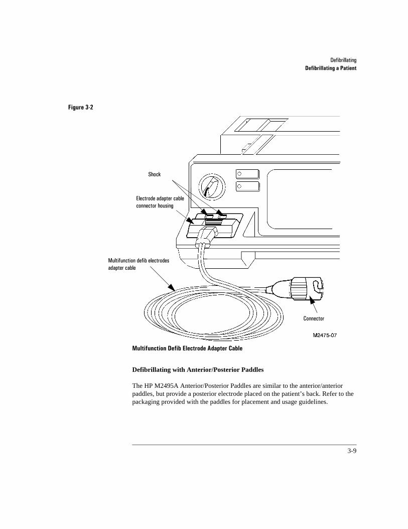
'HILEULOODWLQJDefibrillating a Patient
3-9
Figure 3-2
Multifunction Defib Electrode Adapter Cable 3-2
Defibrillating with Anterior/Posterior Paddles
The HP M2495A Anterior/Posterior Paddles are similar to the anterior/anterior paddles, but provide a posterior electrode placed on the patient’s back. Refer to the packaging provided with the paddles for placement and usage guidelines.
(OHFWURGH�DGDSWHU�FDEOH�FRQQHFWRU�KRXVLQJ
0XOWLIXQFWLRQ�GHILE�HOHFWURGHV�DGDSWHU�FDEOH
6KRFN
�
&RQQHFWRU

'HILEULOODWLQJDefibrillating a Patient
3-10
4-1
4Using Shock Advisory Mode (Optional)
This chapter details the use of Shock Advisory, an option that is available with the HP CodeMaster 100.
In shock advisory mode, the HP CodeMaster 100 acts as a semi-automatic external defibrillator.
When in shock advisory mode the HP CodeMaster 100 can:
• analyze the patient’s ECG rhythms
• advise when a shock should be administered
• automatically charge the defibrillator when a shock is advised
• prompt the user to deliver the shock
• provide advisory event documentation

8VLQJ�6KRFN�$GYLVRU\�0RGH��2SWLRQDO�Understanding Shock Advisory Operating Controls
4-2
4Understanding Shock Advisory Operating Controls
The Shock Advisory mode operating controls on the HP CodeMaster 100 include the Advisory On selection on the Energy Select control and the Analyze button. See Figure 4-1.
Figure 4-1
Shock Advisory Mode Operating Controls 4-1
DEFIBRILLATORENERGY SELECT
Analyze
Advisory On
Monitor On
Off (Standby)
Analyze

8VLQJ�6KRFN�$GYLVRU\�0RGH��2SWLRQDO�Using Shock Advisory Mode
4-3
4Using Shock Advisory Mode
This section provides instructions for using the HP CodeMaster 100 in Shock Advisory mode. Make certain that you observe all safety precautions noted throughout this chapter.
Do not use the HP CodeMaster 100 in Shock Advisory mode for:
•children who weigh less than 90 pounds
•patients who have an implanted pacemaker
The advisory algorithm is not designed to detect pediatric cardiac arrhythmias or handle erratic spiking problems caused by a properly or improperly functioning pacemaker.
The advisory algorithm does not charge the defibrillator to energy levels appropriate for pediatric patients.
To use advisory mode, first verify patient condition. Then:
A Select Advisory On.
B Apply multifunction defib electrodes to the patient.
C Stop patient motion. Press Analyze. If SHOCK ADVISED, stand clear.
D When you hear the charge done tone, press both electrode adapter cable Shock buttons simultaneously.
WARNING

8VLQJ�6KRFN�$GYLVRU\�0RGH��2SWLRQDO�Using Shock Advisory Mode
4-4
Verify Patient Condition
Confirm that the patient is:
• unresponsive
• breathless
• pulseless
A. Select Advisory On
Turn the Energy Select/Power Control to Advisory On to turn on the defibrillator and operate it in advisory mode. The monitor displays:
FOR ANALYSIS, 200JPRESS ANALYZE SELECTED
where 200J is the first energy setting. You can configure the energy settings for the first, second, and third shocks by using the Setup Menu (refer to Chapter 2, “Setup and Configuration”.
You must turn the Energy Select/Power Control to Advisory On before analyzing the ECG. Pressing Analyze has no effect unless the Energy Select/Power On control is set to Advisory On.
In advisory mode, you can use the HP CodeMaster 100 to:
• analyze the patient’s cardiac rhythms by pressing Analyze to determine whether a defibrillation shock is needed
• record events with the advisory event summary
NOTE

8VLQJ�6KRFN�$GYLVRU\�0RGH��2SWLRQDO�Using Shock Advisory Mode
4-5
In advisory mode, the HP CodeMaster 100 emits distinct sounds as described in Table 4-1.
<RX�FDQQRW�GLVDEOH�WKH�FKDUJH�GRQH�WRQH�DQG�&57�VFUHHQ�DOHUWV�IRU�DGYLVRU\�PRGH�LQ�VHWXS�
Table 4-1 Audible Indicators in Advisory Mode
Indicator Description
&KDUJH�'RQH�WRQH &RQWLQXRXV�WRQH�VRXQGV�ZKHQ�WKH�LQVWUXPHQW�LV�FKDUJHG�DQG�UHDG\�WR�GHOLYHU�D�VKRFN��
$XWR�GLVDUP�WRQH 6RXQGV�GXULQJ�WKH�ODVW�WHQ�VHFRQGV�RI�WKH�&KDUJH�'RQH�WRQH��%HHSV�LQWHUPLWWHQWO\�XQWLO�GLVDUPHG�
456�EHHSHU 6RXQGV�ZKHQHYHU�DQ�5�ZDYH�LV�GHWHFWHG��9ROXPH�FRQWUROOHG�E\� �ORFDWHG�RQ�WKH�ORZHU�ULJKW�NH\SDQHO�
&57�6FUHHQ�DOHUWV 7KUHH�EHHSV�HDFK�WLPH�D�PHVVDJH�DSSHDUV�RQ�WKH�VFUHHQ�DQG�ZKHQ�D�VKRFNDEOH�UK\WKP�LV�GHWHFWHG�
6KXWGRZQ�ZDUQLQJ $OWHUQDWLQJ�SLWFK�VRXQGV�IRU����VHFRQGV�ZKHQ�WKH�V\VWHP�LV�DERXW�WR�WXUQ�RII��$Q�DOHUW�WR�UHSODFH�WKH�EDWWHU\�
&KHFN�EDWWHU\�DOHUW 6HW�RI���EHHSV�ZLWK�D�PHVVDJH�CHECK BATTERY�RQ�WKH�PRQLWRU�LQGLFDWLQJ�WKDW�WKH�EDWWHU\�LV�IDXOW\�RU�QRW�ODWFKHG�VHFXUHO\�
456

8VLQJ�6KRFN�$GYLVRU\�0RGH��2SWLRQDO�Using Shock Advisory Mode
4-6
When you turn the Energy Select control to Advisory On, you disable other HP CodeMaster 100 functions including:
• charge key
• 12-Lead option
• pacing
• synchronized cardioversion
• SpO2 monitoring
• lead selection
• leads monitoring
• heart rate alarms
• automatic recordings
• standard event summary generation
• recorder delay mode
• external paddles
• pediatric energy levels
To restore these functions, turn the Energy Select control to Monitor On or an energy setting.
If you turn the Energy Select control to Monitor On or a specific energy setting, you place the HP CodeMaster 100 in manual mode and the advisory features are disabled.
NOTE
8VLQJ�6KRFN�$GYLVRU\�0RGH��2SWLRQDO�Using Shock Advisory Mode
4-7
In Advisory Mode, the Charge button is disabled and the defibrillator cannot be charged manually. To perform manual defibrillation, refer to “Defibrillating a Patient” on page 3-1.
Do not use advisory mode for long term monitoring. Turn the defibrillator to Monitor On for long term patient monitoring.
The Heart Rate (HR) meter is the same for manual or advisory mode when displaying or printing HR information.
The shock advisory algorithm uses a HR meter specifically developed for use by the algorithm for making shock decisions when rate information is required.
B. Apply Defib Electrode
You must use the electrode adapter cable and multifunction defib electrodes in the Apex-Anterior position to analyze patient cardiac rhythms when in Advisory mode.
You must use the electrode adapter cable and multifunction defib electrodes when in advisory mode. The HP CodeMaster 100 will not analyze patient cardiac rhythms through external or internal paddle sets. The message ATTACH PADS CABLE displays if the defib electrode adapter cable is not connected.
The defib electrodes allow accurate analysis of the cardiac rhythms and allow the defibrillator shock to be delivered. You must ensure the electrodes are correctly placed on the patient and attached to the electrode adapter cable. Also ensure the electrode adapter cable is correctly connected to the HP CodeMaster 100.
WARNING
NOTE
WARNING
8VLQJ�6KRFN�$GYLVRU\�0RGH��2SWLRQDO�Using Shock Advisory Mode
4-8
The unit will deliver defibrillator energy levels to a set of multifunction defib electrodes even if they are not attached to a patient. The message PADS OFF appears when there are no electrodes or there is poor electrodes-to-patient contact. Check all patient connections if one these messages appears.
1 Attach the electrode adapter cable (M2472A) to the paddle connector on the front of the defibrillator.
2 Slide the paddle connector lock towards the front of the defibrillator to secure the cable. See Figure 4-2.
WARNING

8VLQJ�6KRFN�$GYLVRU\�0RGH��2SWLRQDO�Using Shock Advisory Mode
4-9
Figure 4-2
Connect Electrode Adapter Cable 4-2
3 Attach the multifunction defib electrodes to the patient as instructed on the package.
Use the Apex-Anterior electrode application shown on the package. This results in the modified Lead II configuration upon which the advisory algorithm was designed and tested.
M2475-B0012
WARNING
8VLQJ�6KRFN�$GYLVRU\�0RGH��2SWLRQDO�Using Shock Advisory Mode
4-10
4 Connect the electrodes to the electrode adapter cable. The electrodes are cor-rectly connected when the locking ring is twisted, locking the ears of the con-nector to the adapter cable.
Be sure to correctly connect the electrodes to the electrode adapter cable. Incorrectly connecting the electrodes to the adapter cable can result in a failure to deliver energy to the patient.
C. Press the Analyze Button
When you place the HP CodeMaster 100 in Advisory mode, the monitor displays the following message:
FOR ANALYSIS, 200JPRESS ANALYZE. SELECTED
Begin analyzing the patient’s ECG by pressing Analyze on the instrument front panel. See Figure 4-3.
WARNING
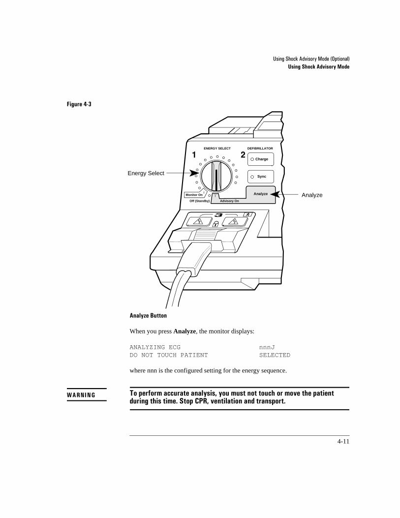
8VLQJ�6KRFN�$GYLVRU\�0RGH��2SWLRQDO�Using Shock Advisory Mode
4-11
Figure 4-3
Analyze Button 4-3
When you press Analyze, the monitor displays:
ANALYZING ECG nnnJDO NOT TOUCH PATIENT SELECTED
where nnn is the configured setting for the energy sequence.
To perform accurate analysis, you must not touch or move the patient during this time. Stop CPR, ventilation and transport.
�
Charge
DEFIBRILLATORENERGY SELECT
Sync
Analyze
Advisory On
Monitor On
Off (Standby)
Energy Select
Analyze
WARNING
8VLQJ�6KRFN�$GYLVRU\�0RGH��2SWLRQDO�Using Shock Advisory Mode
4-12
The advisory algorithm needs 7 to 10 seconds of continuous, artifact free ECG data to decide whether the patient requires defibrillating.
If excessive artifact due to CPR or patient transport is detected, the monitor displays the messages:
ARTIFACT DETECTEDDO NOT TOUCH PATIENT.
If the artifact ends within 20 seconds, analysis continues. Otherwise, the following messages appear on the monitor, and analysis stops. You can restart analysis by pressing Analyze.
ARTIFACT DETECTEDCANNOT ANALYZE
Pressing the Analyze key during analysis will stop analysis. The message ANALYSIS STOPPED will be displayed momentarily, and then the following message appears:
FOR ANALYSIS, 200JPRESS ANALYZE SELECTED
If the multifunction defib electrodes are not properly attached to the patient when you press Analyze, the following message appears.
FOR ANALYSIS, 200JATTACH PADS SELECTED
The electrodes must be attached to the patient and the electrode adapter cable to start analysis.
NOTE
NOTE

8VLQJ�6KRFN�$GYLVRU\�0RGH��2SWLRQDO�Using Shock Advisory Mode
4-13
If the electrode adapter cable is not connected to the HP CodeMaster 100, the message ATTACH PADS CABLE appears. The electrode adapter cable must be connected to start analysis.
D. Follow Prompts
Look frequently at the monitor and follow the displayed instructions. The monitor may display SHOCK ADVISED or NO SHOCK ADVISED.
Shock Advised
When a shockable rhythm is detected, the message SHOCK ADVISED displays and the defibrillator begins charging. The defibrillator charges to the pre-set energy select sequence for the first, second, and third shocks. Subsequent shocks are delivered at the third shock energy level. The charge done tone sounds to alert you that the defibrillator is charged, and the system displays the following messages:
CLEAR PATIENT!PRESS SHOCK BUTTONS
Defibrillating a Patient
1 Verify that no one is in contact with the patient, the cable or pad electrodes, the bed rails, or other potential current path.
2 Call out “Clear!” to alert personnel that a defibrillator shock is about to be deliv-ered and to remain away from the patient.
3 Press both Shock buttons simultaneously to defibrillate. The Shock but-tons are on the cable connector housing shown in Figure 4-4. If the defibrillator does not shock, refer to Chapter 12, “Troubleshooting”.
NOTE
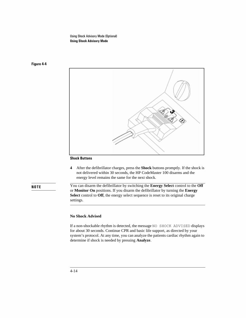
8VLQJ�6KRFN�$GYLVRU\�0RGH��2SWLRQDO�Using Shock Advisory Mode
4-14
Figure 4-4
Shock Buttons 4-4
4 After the defibrillator charges, press the Shock buttons promptly. If the shock is not delivered within 30 seconds, the HP CodeMaster 100 disarms and the energy level remains the same for the next shock.
You can disarm the defibrillator by switching the Energy Select control to the Off or Monitor On positions. If you disarm the defibrillator by turning the Energy Select control to Off, the energy select sequence is reset to its original charge settings.
No Shock Advised
If a non-shockable rhythm is detected, the message NO SHOCK ADVISED displays for about 30 seconds. Continue CPR and basic life support, as directed by your system’s protocol. At any time, you can analyze the patients cardiac rhythm again to determine if shock is needed by pressing Analyze.
NOTE

8VLQJ�6KRFN�$GYLVRU\�0RGH��2SWLRQDO�Using Shock Advisory Mode
4-15
After Using the Defibrillator
If you want to print an Event Summary now, press Review. (See “Printing the Advisory Event Summary Record” on page 4-16.) After you use the defibrillator, perform the following steps to prepare the defibrillator for its next use.
o Clean all paddles, controls, and cables. Visually check the patient cables, paddles, paddles cables, and pads adapter cables for wear, insulation nicks, and other damage. Refer to Chapter 13, “Maintenance” for additional information.
o Turn on the HP CodeMaster 100. If the instrument displays LOW BATTERY, replace the battery pack with a charged battery.
o Perform the test described in “Delivered Energy and Shock Button Functional Test” on page 13-3.
o Turn the Energy Select control to Off and return the HP CodeMaster 100 to its storage location.
o Check that sufficient recorder paper and electrolyte medium or multifunction defib electrodes are available for the next use of the defibrillator.
o Make sure that a battery is in the battery support system being charged. See “Charging the Battery” on page 13-14.

8VLQJ�6KRFN�$GYLVRU\�0RGH��2SWLRQDO�Printing the Advisory Event Summary Record
4-16
4Printing the Advisory Event Summary Record
The advisory event summary record contains information about the resuscitation attempt while in advisory mode. When you print the summary, a header record and event summary directory print before the stored ECGs. ECGs related to events print after the directory record.
The advisory event summary record, which is available only in advisory mode, is independent of the event summary described in “Printing the Event Summary Record” on page 5-12, which is available only in manual mode.
Passing through the 2II position on the (QHUJ\�6HOHFW�switch more than once from Advisory Mode to Manual Mode and the initiation of an Event creates a new patient summary record which could cause data loss.
NOTE
CAUTION

8VLQJ�6KRFN�$GYLVRU\�0RGH��2SWLRQDO�Printing the Advisory Event Summary Record
4-17
Figure 4-5
Advisory Event Summary Record 4-5
To print the advisory event summary record, press Review.
To stop printing the advisory event summary, press Review or Record.
To review the advisory event summary after the instrument has been turned off or is turned to manual mode, turn the Energy Select control to Advisory On and press Review.
The header record lists when power on occurred, when the last event occurred, and how many shocks were delivered. The record also includes areas for you to write in the patient’s name, the operator’s name, and any comments about the event.
The directory lists all events that occurred during the resuscitation attempt and the time of their occurrence.

8VLQJ�6KRFN�$GYLVRU\�0RGH��2SWLRQDO�Printing the Advisory Event Summary Record
4-18
The following table lists the events the directory shows.
Table 4-2 Advisory Event Summary Record Information
Event Description Notes
$QDO\]LQJ ,QGLFDWHV�ZKHQ�WKH�DGYLVRU\�DOJRULWKP�VWDUWHGDQDO\VLV��Analyze SUHVVHG���
$UWLIDFW�'HWHFWHG ,QGLFDWHV�WKDW�WKH�DGYLVRU\�DOJRULWKP�GHWHFWHG�H[FHVVLYH�DUWLIDFW�
6KRFN�$GYLVHG ,QGLFDWHV�ZKHQ�WKH�DGYLVRU\�DOJRULWKP�GHWHFWHG�D�VKRFNDEOH�UK\WKP�DQG�DGYLVHG�D�VKRFN�
(&*�VWULS�UHFRUGHG
1R�6KRFN�$GYLVHG ,QGLFDWHV�WKDW�WKH�DGYLVRU\�DOJRULWKP�GHWHFWHG�D�QRQ�VKRFNDEOH�UK\WKP�DQG�GLG�QRW�DGYLVH�D�VKRFN�
(&*�VWULS�UHFRUGHG
&DQQRW�$QDO\]H ,QGLFDWHV�WKDW�WKH�DGYLVRU\�DOJRULWKP�FRXOG�QRW�DQDO\]H�WKH�FDUGLDF�UK\WKP�GXH�WR�H[FHVVLYH�DUWL�IDFW�
(&*�VWULS�UHFRUGHG
$QDO\VLV�6WRSSHG ,QGLFDWHV�WKDW�WKH�XVHU�VWRSSHG�WKH�DGYLVRU\�DOJRULWKP�DQDO\VLV�E\�SUHVVLQJ�WKH�Analyze NH\�GXU�LQJ�DQDO\VLV�
3DGV�2II ,QGLFDWHV�WKDW�WKH�PXOWLIXQFWLRQ�GHILE�HOHFWURGHV�ZHUH�UHPRYHG�IURP�WKH�SDWLHQW�
1R�3DGV ,QGLFDWHV�ZKHQ�HOHFWURGH�DGDSWHU�FDEOH�ZDVGLVFRQQHFWHG�IURP�GHILEULOODWRU�
3DGV�2Q ,QGLFDWHV�ZKHQ�PXOWLIXQFWLRQ�GHILE�HOHFWURGHV�ZHUHFRQQHFWHG�WR�WKH�SDWLHQW�
0DUN 0DUNHU�V\PERO��t��DQQRWDWHV�VWULS�ZKHQ�Mark�ZDV�SUHVVHG�
(&*�VWULS�UHFRUGHG
&KDUJLQJ�WR�QQQ- ,QGLFDWHV�ZKHQ�DXWRPDWLF�FKDUJH�VHTXHQFH�EHJDQ��DIWHU�DGYLVRU\�DOJRULWKP�DGYLVHG�D�VKRFN��
6KRFN ,QGLFDWHV�ZKHQ�VKRFN�ZDV�GHOLYHUHG��GHOLYHUHG�HQHUJ\��SHDN�FXUUHQW�DQG�SDWLHQW�LPSHGDQFH�
(&*�VWULS�UHFRUGHG
'LVDUP ,QGLFDWHV�ZKHQ�WKH�GHILEULOODWRU�SHUIRUPHG�DQLQWHUQDO�GLVDUP�VHTXHQFH�

8VLQJ�6KRFN�$GYLVRU\�0RGH��2SWLRQDO�Printing the Advisory Event Summary Record
4-19
The HP CodeMaster 100 automatically records 11 second ECG strips for Shock Advised, No Shock Advised and Cannot Analyze events. You can record other events by pressing Mark. For Mark events and shock events, ECGs are written from 3 seconds before the event to 8 seconds after the event is over. Approximately 200 events and 50 ECG strips can be stored.
Figure 4-6 shows a sample ECG strip.
Figure 4-6
Sample ECG Strip 4-6
Clearing Advisory Event Memory
The instrument retains event information after you turn the instrument off. Memory clears when the HP CodeMaster 100 is turned on, placed in Advisory Mode, and Analyze pressed or a new ECG strip is recorded (see Table 4-2, “Advisory Event Summary Record Information”). Memory does not clear if the HP CodeMaster 100 is simply turned on, or if the instrument is used in manual mode. This allows you to turn the instrument off or enter manual mode and later return to advisory mode to print the advisory event summary record.
Turn the defibrillator off between patients to ensure that the advisory event summary records are patient specific.
SHOCK ADVISED 12 MAY 95 10:59:00 PADS x1.00 AES
NOTE
8VLQJ�6KRFN�$GYLVRU\�0RGH��2SWLRQDO�Advisory Mode Default Settings
4-20
4Advisory Mode Default Settings
The HP CodeMaster 100 contains default settings for use in Advisory mode. Some of the settings can be altered using the Setup Menu.
The following settings can be changed:
• Default energy select sequence. You can choose to change the sequence from the factory default settings for a sequence of 200, 200, and 360 Joules, to a sequence of 200, 300, and 360 Joules. The energy level for the third shock and all subse-quent shocks will be 360 Joules.
• Post Shock Data: On/Off.
When operating in Advisory mode, the following settings cannot be changed:
• Charge done tone: always sounds.
• CRT alert tones: always sounds.
• Alert tone volume: always at the maximum volume.
• Recorder delay: no delay.
• Recorder Bandwidth: always Monitor bandwidth.
• Automatic Recordings: always off.
• Power on Lead: always PADS/PADDLES.
• Notch Filter: always on.

5-1
5Monitoring
This chapter contains information about monitoring a patient with the HP CodeMaster 100, details of patient preparation that apply to the synchronized cardioversion, and pacing procedures.
The HP CodeMaster 100 can be used for either short-term or long-term cardiac monitoring. A fully charged HP M2476B 2.5 amp-hour NiCd battery provides a minimum of two hours of continuous monitoring. A fully charged HP M2477B 4.0 amp-hour NiCd battery provides a minimum of three hours of continuous monitoring time.
Not intended for use with internal electrodes.CAUTION
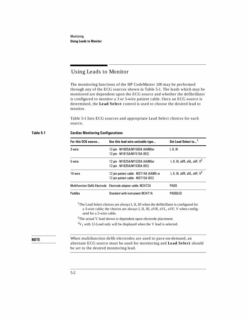
0RQLWRULQJUsing Leads to Monitor
5-2
5Using Leads to Monitor
The monitoring functions of the HP CodeMaster 100 may be performed through any of the ECG sources shown in Table 5-1. The leads which may be monitored are dependent upon the ECG source and whether the defibrillator is configured to monitor a 3 or 5-wire patient cable. Once an ECG source is determined, the Lead Select control is used to choose the desired lead to monitor.
Table 5-1 lists ECG sources and appropriate Lead Select choices for each source.
1The Lead Select choices are always I, II, III when the defibrillator is configured for a 3-wire cable; the choices are always I, II, III, aVR, aVL, aVF, V when config-ured for a 5-wire cable.
2The actual V lead shown is dependent upon electrode placement.3V1 with 12-Lead only will be displayed when the V lead is selected.
When multifunction defib electrodes are used to pace-on-demand, an alternate ECG source must be used for monitoring and Lead Select should be set to the desired monitoring lead.
Table 5-1 Cardiac Monitoring Configurations
For this ECG source... Use this lead wire set/cable type... Set Lead Select to...1
��ZLUH� ���SLQ���0����$�0����$��$$0,�RU���SLQ���0����$�0����$��,(&�
,��,,��,,,
��ZLUH� ���SLQ���0����$�0����$��$$0,�RU���SLQ���0����$�0����$��,(&�
�,��,,��,,,��D95��D9/��D9)��9�
���ZLUH ���SLQ�SDWLHQW�FDEOH���0����$��$$0,��RU����SLQ�SDWLHQW�FDEOH���0����$��,(&�
�,��,,��,,,��D95��D9/��D9)��9�
0XOWLIXQFWLRQ�'HILE�(OHFWURGH (OHFWURGH�DGDSWHU�FDEOH��0����$ 3$'6
3DGGOHV 6WDQGDUG�ZLWK�LQVWUXPHQW�0����$ 3$''/(6
NOTE
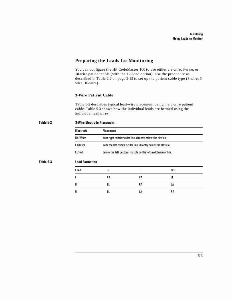
0RQLWRULQJUsing Leads to Monitor
5-3
Preparing the Leads for Monitoring
You can configure the HP CodeMaster 100 to use either a 3-wire, 5-wire, or 10-wire patient cable (with the 12-Lead option). Use the procedure as described in Table 2-2 on page 2-12 to set up the patient cable type (3-wire, 5-wire, 10-wire).
3-Wire Patient Cable
Table 5-2 describes typical lead-wire placement using the 3-wire patient cable. Table 5-3 shows how the individual leads are formed using the individual leadwires.
Table 5-2 3-Wire Electrode Placement
Electrode Placement
5$�:KLWH 1HDU�ULJKW�PLGFODYLFXODU�OLQH��GLUHFWO\�EHORZ�WKH�FODYLFOH�
/$�%ODFN 1HDU�WKH�OHIW�PLGFODYLFXODU�OLQH��GLUHFWO\�EHORZ�WKH�FODYLFOH��
//�5HG %HORZ�WKH�OHIW�SHFWRUDO�PXVFOH�RQ�WKH�OHIW�PLGFODYLFXODU�OLQH�
Table 5-3 Lead Formation
Lead + − ref
, /$ 5$ //
,, // 5$ /$
,,, // /$ 5$
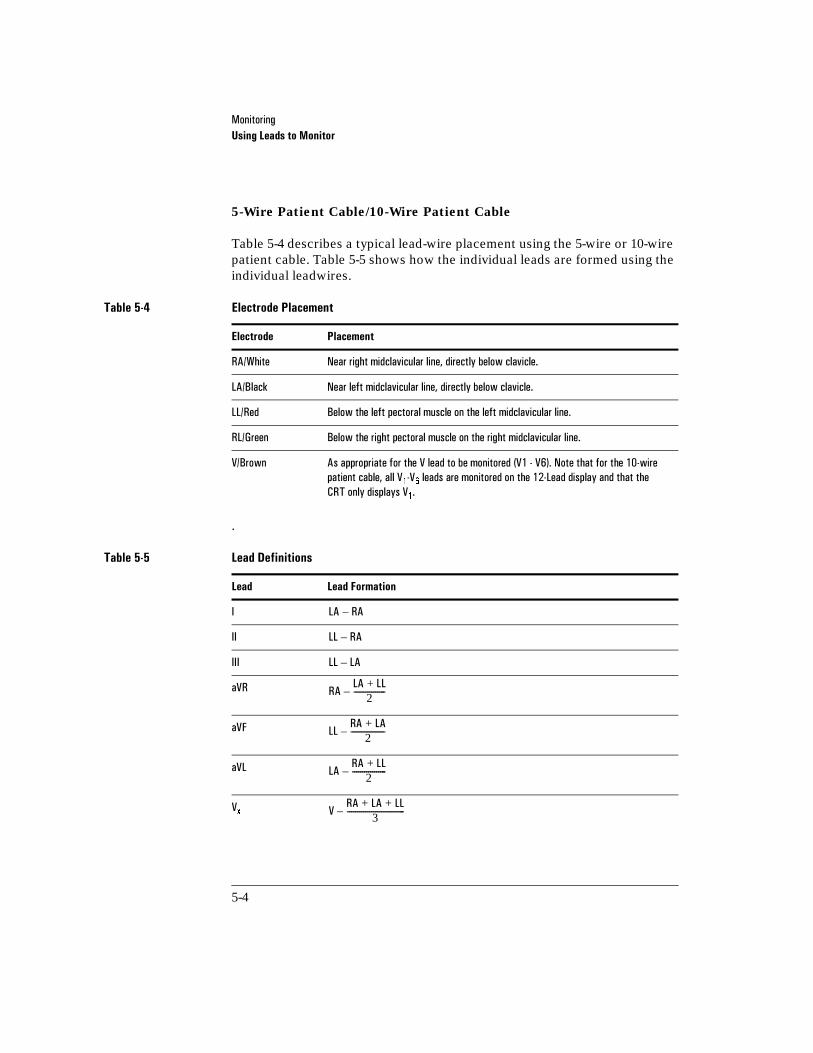
0RQLWRULQJUsing Leads to Monitor
5-4
5-Wire Patient Cable/10-Wire Patient Cable
Table 5-4 describes a typical lead-wire placement using the 5-wire or 10-wire patient cable. Table 5-5 shows how the individual leads are formed using the individual leadwires.
.
Table 5-4 Electrode Placement
Electrode Placement
5$�:KLWH 1HDU�ULJKW�PLGFODYLFXODU�OLQH��GLUHFWO\�EHORZ�FODYLFOH��
/$�%ODFN� 1HDU�OHIW�PLGFODYLFXODU�OLQH��GLUHFWO\�EHORZ�FODYLFOH��
//�5HG� %HORZ�WKH�OHIW�SHFWRUDO�PXVFOH�RQ�WKH�OHIW�PLGFODYLFXODU�OLQH��
5/�*UHHQ %HORZ�WKH�ULJKW�SHFWRUDO�PXVFOH�RQ�WKH�ULJKW�PLGFODYLFXODU�OLQH�
9�%URZQ $V�DSSURSULDWH�IRU�WKH�9�OHDG�WR�EH�PRQLWRUHG��9����9����1RWH�WKDW�IRU�WKH����ZLUH�SDWLHQW�FDEOH��DOO�9��9��OHDGV�DUH�PRQLWRUHG�RQ�WKH����/HDG�GLVSOD\�DQG�WKDW�WKH�&57�RQO\�GLVSOD\V�9���
Table 5-5 Lead Definitions
Lead Lead Formation
,
,,
,,,
D95
D9)
D9/
9[
/$ 5$–
// 5$–
// /$–
5$/$ //+
2----------------–
//5$ /$+
2-----------------–
/$5$ //+
2-----------------–
95$ /$ //+ +
3-----------------------------–
0RQLWRULQJPreparing the Patient
5-5
5Preparing the Patient
Proper application and placement of electrodes is essential for quality ECG monitoring. Good contact between the electrode and the skin reduces the effects of motion artifact and signal interference.
1 If necessary, shave hair from the site to ensure good electrode to skin contact.
2 Clean and abrade the skin then wipe it dry.
You can safely monitor a patient during defibrillation. However, monitoring electrodes can become polarized during defibrillation shock, causing the ECG waveform to briefly disappear from the display. You can reduce this effect by using silver-silver chloride electrodes.
Be sure that the electrodes or lead wire tips do not come in contact with any other conductive materials, including earth-grounded materials, especially when connecting or disconnecting electrodes to/from a patient.
3 Attach disposable monitoring electrodes by performing the following steps:
a. Peel the protective backing from the electrode. Be careful to keep adhesive surface free from electrolyte medium.
b. Apply the electrodes firmly to the patient’s skin, pressing around the entire edge of the electrode.
c. Snap lead wires onto electrodes, assuring good contact between the electrode and the lead end. Tape the lead wire to the skin to prevent the electrode or lead from loosening.
d. Plug the patient cable connector into the ECG input connector on the lower front of the defibrillator, behind the carrying handle.
NOTE
WARNING

0RQLWRULQJPreparing the Patient
5-6
The HP 12-Lead patient cable can only be used with snap ECG monitoring electrodes. Use only Hewlett-Packard approved ECG monitoring electrodes. Do not mix reusable and disposable electrodes.
Be careful to correctly align the cable plug when connecting the patient ECG leads cable to the HP CodeMaster 100. Correctly orient the cable plug key with the connector slot. If the ECG leads cable falls out or is incorrectly connected, the message LEADS OFF appears on the display.
NOTE

0RQLWRULQJPreparing the Patient
5-7
ECG Monitoring Electrodes
Using Multifunction Defib Electrodes
Multifunction defib electrodes (M3501A, M3502A, M3503A, M3504A) allow you to monitor, defibrillate, and perform synchronized cardioversion. In order to perform pacing, you must attach both ECG monitoring electrodes and defib electrodes. To use defib electrodes, perform the following steps.
1 Attach multifunction defib electrodes as instructed on the package.
2 Attach the electrode adapter cable (M2472A) to the defibrillator.
3 Connect the defib electrodes to the electrode adapter cable. The elec-trodes are correctly connected when the locking ring is twisted, locking the ears of the connector to the adapter cable.
4 Use the Lead Select button to select PADS as the ECG source.
Using Paddles
For an emergency evaluation you can monitor a patient’s ECG through the paddles electrodes when leads are not attached to the patient.
Do NOT use paddles to monitor the ECG during elective cardioversion procedures when the HP CodeMaster 100 is in synchronous (SYNC) mode. Refer to Chapter 7, ”Performing Synchronized Cardioversion”, for detailed information on performing elective cardioversion.
WARNING

0RQLWRULQJMonitoring a Patient the CodeMaster 100
5-8
5Monitoring a Patient the CodeMaster 100
Refer to “Monitor Operating Controls” on page 1-7. To monitor a patient's ECG with the HP CodeMaster 100, perform these steps:
1 Prepare the patient for ECG monitoring as described in “Preparing the Patient” on page 5-5.
2 Turn the Energy Select control to the Monitor On position.
3 Press Lead Select to select the ECG source. The selected source appears in the upper right corner of the display. For example, PADS appears on the display when it has been selected.
If the message LEADS OFF or PADS OFF appears on the display, inspect the electrodes, patient cable, leadwires, and associated connections. If the selected ECG source is not connected, a dashed line replaces the normal ECG trace.
4 Ensure that the ECG size has been automatically adjusted for optimal size. If you wish to reduce the ECG size, press ECG Size. The "gain bar" along the left side of the display represents 1 mV of signal amplitude.
Autogain allows an initial quick set up when the HP CodeMaster 100 is turned on to automatically size the ECG based on the signal from the patient. To turn off Autogain, press ECG Size. You then must adjust the ECG size manually.
It is recommended that you manually adjust the gain during routine patient monitoring.
5 Adjust the QRS beeper volume (using ) to the desired volume.
NOTE
QRS

0RQLWRULQJHeart Rate Alarms
5-9
5Heart Rate Alarms
The HP CodeMaster 100 provides three configurable pairs of upper and lower heart rate alarm limits. Each pair of heart rate alarm limits can be defined as described in Table 2-1 on page 2-11. While monitoring, you can select and enable any pair of pre-defined limits using HR Alarm.
When heart rate alarms are inactive, the monitor will display .
To select a pair of heart rate alarm limits, press HR Alarm until the pair of limits you wish to use are displayed. If you do not press the key again, the displayed heart rate alarm limits become active and the limits are replaced by the bell symbol.
If the heart rate alarm limits are violated, the heart rate alarm limits replace the bell symbol, and the violated limit is highlighted. Pressing HR Alarm at this point will turn off the heart rate alarms.
If the heart rate alarms are active and you wish to review the limits, press HR
Alarm. The currently active pair of heart rate alarm limits are displayed momentarily.
If the heart rate alarms are active and you wish to select another pair of limits, press HR Alarm until the pair of limits you wish to use are displayed. Pressing HR Alarm repeatedly cycles through the three pairs of heart rate alarm limits and the heart rate alarms inactive choice.
Heart rate alarms are automatically turned off when you press Charge.NOTE

0RQLWRULQJRecording
5-10
5Recording
Recording operating controls are detailed in “Recorder Operating Controls” on page 1-9.
Recording/Printing ECG and Monitoring Data
To print a record of the current ECG and of the monitor status, press Record.
•The upper line of the ECG strip contains a periodic report of monitor parameters (Date, Time, Heart Rate, ECG Source, ECG Size, and Recorder mode).
•The lower line of the ECG strip records asynchronous events such as Shock delivery or Heart Rate Alarm violations.
•Several graphic symbols are used to annotate events such as Shock, Heart Rate Alarms, Mark, or Sync.
You can print a 1 mV, 200 ms calibration pulse on the ECG strip by pressing both arrows on the ECG Size key simultaneously.
Table 2-2 on page 2-12 contains a list of configuration settings which affect recorder operation. The recorder can be configured for either monitor or diagnostic ECG bandwidth data. Delayed (6 seconds) or non-delayed operation is also configurable.

0RQLWRULQJRecording
5-11
Automatic Recordings
As described in Table 2-2 on page 2-12, you can enable or disable any of the following automatic recordings:
•Record on Mark
•Record on Charge
•Record on Shock
•Record on Alarms
The automatic recordings for both delayed and non-delayed recorder modes of operation are defined in Table 5-6. All event summaries (except for shock advisory) are 3 seconds pre- and 8 seconds post-events. If in delayed mode, each event prints with a 6 second pre-event strip prior to the event.
Table 5-6 Automatic Recordings
EventDelayed mode Post-event time
Non-Delayed mode Post-event time
Mark SUHVVHG ��VHFRQGV ��VHFRQGV
&KDUJH 8QWLO�6KRFN�RU�'LVDUP�HYHQW 8QWLO�6KRFN�RU�'LVDUP�HYHQW
6KRFNLQJ�WKH�SDWLHQW ���VHFRQGV ���VHFRQGV
$ODUPV�YLRODWLRQ ��VHFRQGV ��VHFRQGV
'LVDUP ��VHFRQGV ��VHFRQGV
7HVW�GLVFKDUJH ��VHFRQGV ��VHFRQGV�

0RQLWRULQJRecording
5-12
Post Shock Data
As described in Table 2-2 on page 2-12, you can enable or disable the recording of post shock statistics.
•If Post Shock Data is enabled, the defibrillator will record the shock deliv-ery statistics (Actual Delivered Energy, Patient Impedance, Peak Current).
•If Post Shock Data is disabled, the defibrillator will record the energy to which it was charged as the delivered energy. For example, if the unit was charged to 200J, the delivered energy annotation on the ECG strip would be DEL 200J.
Printing the Event Summary Record
During defibrillator usage, the monitor stores up to 28 ECG strips of critical information called events. Events include all shocks, heart rate alarm violations, SpO2 alarm violations, and mark events. Each event record includes date of event, heart rate, SpO2 reading, ECG source, and size setting as shown in Table 5-7. The time annotated on the ECG strip is within 8 seconds of the recorded event. The message "ES" is printed at the top of the ECG strip when you print the Event Summary record.
•To print the Event Summary on the recorder, press Review. The recorder must not be printing to print an Event Summary with this key.
•To stop printing the Event Summary, press Review or Record.
•To review the Event Summary later, turn the unit on and press Review.
Table 5-7 Event Summary Record Information
Event Event Summary Description
6KRFN 6KRFN���'HOLYHUHG�HQHUJ\��SHDN�FXUUHQW�DQG�SDWLHQW�LPSHGDQFH��
+HDUW�5DWH�$ODUPV�YLRODWLRQ +HDUW�5DWH�DODUP�OLPLWV�
6S2��$ODUPV�YLRODWLRQ 6S2��DODUP�OLPLWV�
Mark 0DUNHU�V\PERO�� ��DQQRWDWHV�VWULS�DW�SRLQW Mark ZDV�SUHVVHG��
0RQLWRULQJRecording
5-13
The Event Summary record is cleared each time the defibrillator is turned on and a new event occurs. This allows you to turn off the defibrillator and return later to review event information such as code statistics.
Turn the defibrillator off between uses to ensure that Event Summary records are patient specific.
Recorder Errors
The message CHECK RECORDER appears on the screen if an error occurs while recording. If this message appears, check the recorder paper supply. This message may also appear if the recorder door is open.
NOTE

0RQLWRULQJExternal Monitoring
5-14
5External Monitoring
The ECG output provides an analog 1V/mV ECG signal for connection to a Hewlett-Packard external monitor. Hewlett-Packard compatible external monitoring divider cables are as follows.
The ECG output is also compatible with the interface to the HP Viridia Information Center and other HP central stations.
Do not use the ECG output to synchronize another defibrillator. (The ECG-In to ECG-Out delay is 35 milliseconds.)
The connection of external equipment may increase leakage currents. Always request that local safety personnel verify that multiple connected equipment comply with local regulatory standards before putting such equipment into service.
Table 5-8 External Monitoring Cables
1000:1 Voltage Divider Cable Connector Type HP Part No.
7ZHOYH�3LQ �0����$
6L[�3LQ 0����$
NOTE
NOTE
WARNING

6-1
6Using the 12-Lead Option
6Introduction
The 12-Lead option adds12-Lead electrocardiograph capabilities to the HP CodeMaster 100. It enables you to view, acquire, store, print, and transmit 12-Lead ECGs. You can configure this feature to provide an interpretation of the ECG to further aid in patient diagnosis. The 12-Lead option includes:
•12-Lead acquisition and printing for on-site interpretation
•preview display to scroll through all l2 leads
•computerized ECG analysis or interpretation
•internal modem (US, Canada, and UK) and combined landline/cellular for ECG transmission
•RS-232 port for use with external modem
•phone directory with auto dial with storage of up to 18 transmission sites
•storage of up to 30 ECGs
•backlit LCD display
•shared patient cable connector with the HP CodeMaster 100
•compatible with HP TraceMaster ECG Management System (M1730B or M1729B) and HP ECG Manager (M1765A)

8VLQJ�WKH����/HDG�2SWLRQ12-Lead Keyboard and Display
6-2
612-Lead Keyboard and Display
This section discusses the 12-Lead keyboard and provides detailed descriptions of all the function keys. Refer to Figure 6-1 for an illustration of the 12-Lead keyboard.

8VLQJ�WKH����/HDG�2SWLRQ12-Lead Keyboard and Display
6-3
Figure 6-1
12-Lead Keyboard and Front Panel 6-1
ID
12-Lead
Send
F5F4F3F2F1
Q W E R T Y U I O P 7 =
4 :
1 ’
0 )
8 -
5 %
2 .
Filter
9 (
6 +
3 ;
Copy
A S < D > F ? G / H " J ’ K L
Shift
Alt
Z & X * C @ V ^ B # N ! M ~
Stop
Menu
Shift
M2475-B0004

8VLQJ�WKH����/HDG�2SWLRQ12-Lead Keyboard and Display
6-4
Table 6-1 12-Lead Keyboard
Key Description
'LVSOD\V�WKH�0DLQ�PHQX��XQOHVV�DQ�(&*�UHSRUW�LV�LQ�SURFHVV��8VH�WKH�6723�NH\�WR�UHWXUQ�WR�WKH�KRPH�VFUHHQ�RQ�WKH����/HDG�GLVSOD\�
7KHVH�ILYH�NH\V��)��²�)����ORFDWHG�GLUHFWO\�EHQHDWK�WKH�GLVSOD\�ZLQGRZ��SHUIRUP�GLIIHUHQW�IXQFWLRQV�DW�GLIIHUHQW�WLPHV��7KH\�DUH�FDOOHG�´VRIWNH\V�µ�:KHQ�D�VRIWNH\�LV�DFWLYH��D�ODEHO�GHVFULELQJ�LWV�IXQFWLRQ�LV�GLVSOD\HG�DERYH�LW�RQ�WKH�VFUHHQ��3UHVV�WKH�NH\�WR�SHUIRUP�WKH�IXQFWLRQ�GLVSOD\HG�RQ�WKH�VFUHHQ�
8VHG�WR�HQWHU�VKLIWHG�FKDUDFWHUV�
7R�HQWHU�WKH�FKDUDFWHUV�VKRZQ�DERYH�WKH�OHWWHU�NH\V��VHH�)LJXUH�����IRU�ODQ�JXDJH�VSHFLILF�NH\V���SUHVV�WKH� �NH\�ZLWK�WKH�GHVLUHG�OHWWHU�
$OORZV�SDWLHQW�LGHQWLILFDWLRQ�HQWU\��UHYLHZ��DQG�HGLW�
,QLWLDWHV����/HDG�(&*�DFTXLVLWLRQ�
,QLWLDWHV�(&*�WUDQVPLVVLRQ�
7XUQV�ILOWHUV�RQ�DQG�RII��7KH�ILOWHU��RU�ILOWHUV��FRQWUROOHG�E\�WKLV�NH\�DUH�VHOHFWHG�GXULQJ����/HDG�FRQILJXUDWLRQ�
7KH�Enter�NH\�
+DOWV�DQ\����/HDG�DFWLYLW\�DQG�UHVWRUHV�WKH�QRUPDO�(&*�GLVSOD\�
3ULQWV�D�FRS\�RI�WKH�ODVW�(&*��,I�DQ�(&*�LV�QRW�LQ�WKH�&RS\�EXIIHU��WKH�V\VWHP�GLV�SOD\V�WKH�0DQDJH�6WRUHG�(&*V�VFUHHQ�DQG�SURPSWV�\RX�WR�VHOHFW�WKH�(&*�WR�SULQW��7KH�VHWWLQJ�IRU�WKLV�NH\�GHIDXOWV�WR�WKH�QXPEHU�RI�FRSLHV�VHW�LQ�WKH�&RS\�&RXQW�IHD�WXUH������FRSLHV�ZLWK�D�GHIDXOW�RI����
7R�YLHZ�OHDG�JURXSV��XVH�WKH� �RU� �NH\V�WR�PRYH�WR�WKH�QH[W�OHDG�JURXS��DQG�WKH� �RU� �NH\V�WR�PRYH�WR�WKH�SUHYLRXV�OHDG�JURXS��7KH� �RU� �NH\V�PRYH�WKH�FXUVRU�GRZQ�RQ�FRQILJXUDWLRQ�GLVSOD\V�DQG�SDWLHQW�,'�LQIRUPDWLRQ�VFUHHQV��7KH� �DQG� �NH\V�PRYH�WKH�FXUVRU�XS�
0HQX
VRIWNH\V
6KLIW
$OW$OW
,'
���/HDG
6HQG
)LOWHU
6WRS
&RS\

8VLQJ�WKH����/HDG�2SWLRQ12-Lead Keyboard and Display
6-5
Figure 6-2
Characters by Language 6-2

8VLQJ�WKH����/HDG�2SWLRQPatient and Operational Safety Notes
6-6
6Patient and Operational Safety Notes
The HP CodeMaster 100 with the 12-Lead option isolates all connections to the patient from electrical ground. This reduces the possibility of hazardous currents passing from the device through the patient’s heart to ground. To ensure the patient’s safety and your own, observe the following reminders:
The HP patient cable supplied with this device, or an HP approved substitute patient cable, is an integral part of the defibrillator/monitor safety features. Using any other patient cable may compromise defibrillation protection as well as performance. Only qualified personnel may service the device.
Do not use the HP CodeMaster 100 with 12-Lead near flammable anesthetics. It is not intended for use in explosive environments.
Do not use the HP CodeMaster 100 with 12-Lead in the presence of electrosurgical or diathermy instruments.
Do not touch the patient or patient cable during defibrillation. Death or injury may occur from the electrical shock delivered by the defibrillator.
Be sure that the electrodes or connectors do not come in contact with any other conductive materials, including earth-grounded materials, especially when connecting or disconnecting electrodes to/from a patient.
The use of multiple instruments connected to the same patient may pose a safety hazard due to the summation of leakage currents from each instrument. Any combination of instruments should be evaluated by local safety personnel before being put into service.
Do not pull on the paper while a report is being printed. This can cause distortion of the waveform and can lead to potential misdiagnosis.
WARNING
WARNING

8VLQJ�WKH����/HDG�2SWLRQPatient and Operational Safety Notes
6-7
The connection of an external modem or other telecommunications equipment may increase leakage currents beyond levels that are acceptable in a patient care environment. Always request that local safety personnel verify that multiple connected equipment comply with local requlatory standards before putting such equipment into service.
WARNING

8VLQJ�WKH����/HDG�2SWLRQAcquiring a 12-Lead ECG
6-8
6Acquiring a 12-Lead ECG
This section describes how to:
• prepare the patient for an ECG
• check the signal quality of the patient leads
• enter patient ID and printed report information
• record an ECG
• change the report format
• understand the printed report

8VLQJ�WKH����/HDG�2SWLRQAcquiring a 12-Lead ECG
6-9
To Acquire a 12-Lead ECG:
If your HP CodeMaster 100 with 12-Lead is already configured, you can acquire an ECG by performing the following steps:
1 Connect the 12-Lead ECG cable to the patient.
2 Turn the Energy Select control to Monitor On.
3 Prepare the patient and apply the electrodes, as described in “Preparing the Patient” on page 6-10.
4 Check the signal quality on all leads.
5 Press the ID key and enter patient ID information.
6 Press the 12-Lead key to obtain an ECG.
If you are using HP ACI-TIPI or TPI, the system prompts you for any missing information required for HP ACI-TIPI or TPI. See “Using HP ACI-TIPI” on page 6-18 and “Using HP TPI” on page 6-19.
The status messages Acquiring ECG..., Processing..., Analyzing... Storing ECG..., and Printing... are displayed.Wait for the report to print.If you have configured the 12-Lead option to Auto Send, the system displays the telephone directory.
If the memory is full and you attempt to store a new ECG, the system will “auto delete” the oldest stored ECG.
.
NOTE

8VLQJ�WKH����/HDG�2SWLRQAcquiring a 12-Lead ECG
6-10
Preparing the Patient
For electrode placement information, refer to Figure 6-3.
Figure 6-3
Electrode Placement 6-3
LL/FRA/R
RL/N
V4/C4
V5/C5
V6/C6
LA/L
V1/C1
V2/C2
V3/C3
Lead Position
V1/C1 Fourth intercostal space, at right sternal margin.
V2/C2 Fourth intercostal space, at left sternal margin.
V3/C3 Midway between V2 and V4.
V4/C4 Fifth intercostal space, at left midclavicular line.
V5/C5 Same level as V4, on anterior axillary line.
V6/C6 Same level as V4, at left midaxillary line.
RA/R Inside of arm, between wrist and elbow.
LA/L Inside of arm, between wrist and elbow.
RL/N Inside of calf, between knee and ankle.
LL/F Inside of calf, between knee and ankle.

8VLQJ�WKH����/HDG�2SWLRQAcquiring a 12-Lead ECG
6-11
For tips on proper ECG technique, see the quick reference card included with this product located in the carry bag front/top panel.
Proper patient preparation and electrode placement are the most important elements in producing a high quality ECG trace. The patient should be supine when acquiring an ECG. If this is not possible, note the patient’s position and ensure this factor is considered for diagnosis.
Prepare the patient by performing the following steps.
1 Reassure and relax the patient.
2 Make sure the electrode site is not covered by hair or clothing.Prepare the skin to ensure good contact between the skin and the electrode by gently cleaning and abrading the surface of the skin with dry gauze.
3 Place electrodes on the patient.
4 Attach each lead wire to the correct electrode.
5 The upper-left corner of the screen displays the electrodes that are not placed firmly on the patient and/or the lead wires that are not attached securely to the electrodes. (See Table 6-2.) This is an indication of “leads off”. Correct the attachment of any lead/electrode pair that appears on the screen.
NOTE

8VLQJ�WKH����/HDG�2SWLRQAcquiring a 12-Lead ECG
6-12
Checking Signal Quality
You can produce better ECGs by previewing the lead traces on the upper display before you acquire and print the ECG. By observing the traces and adjusting the leads accordingly, you can obtain the best possible ECG report.
The leads are displayed in five groups of three leads each. The groups are listed in Table 6-3.
Restoring the ECG Trace
After application of a defibrillator pulse, reconnecting one or more leads, or any other time the ECG signal is off-center during ECG acquisition, traces can be quickly restored by pressing the Stop key.
Table 6-2 Leads Off Labels
Designator(AHA/IEC)
Meaning
5/�1 5LJKW�OHJ�HOHFWURGH�QRW�FRQQHFWHG�or�RQO\�ULJKW�OHJ�HOHFWURGH�LV�FRQQHFWHG�DQG�DOO�RWKHU�OLPE�HOHFWURGHV�DUH�QRW�FRQQHFWHG�
5$�5 5LJKW�DUP�HOHFWURGH�LV�QRW�FRQQHFWHG�
/$�/ /HIW�DUP�HOHFWURGH�LV�QRW�FRQQHFWHG�
//�) /HIW�OHJ�HOHFWURGH�LV�QRW�FRQQHFWHG�
9����9��&����&�
2QH�RU�PRUH�FKHVW�HOHFWURGHV�DUH�QRW�FRQQHFWHG��)RU�H[DPSOH��9��PHDQV�WKH�9��HOHFWURGH�LV�QRW�FRQQHFWHG�

8VLQJ�WKH����/HDG�2SWLRQAcquiring a 12-Lead ECG
6-13
• To select which three leads to display on the screen, press the or key, or
the Space bar, to display the next lead group, or press the or key to display
the previous lead group.
• Before you connect the electrodes, each lead displays on the screen as a dotted line, indicating that at least one of the electrodes associated with the lead is not connected. The dotted line is known as a “leads off” trace. Use the leads off labels (see Table 6-2) to determine which electrodes are off.
• As you connect the electrodes to the patient, the lead waveforms are displayed on the screen.
The ECG traces are updated by the erase bar that moves across the screen.
Table 6-3 Lead Groups
Group Leads Displayed
Group 1 I, II, III
Group 2 aVR, aVL, aVF
Group 3 V1, V2, V3
Group 4 V4, V5, V6
Group 5 user configurable
NOTE

8VLQJ�WKH����/HDG�2SWLRQAcquiring a 12-Lead ECG
6-14
Entering Patient ID
Entering patient ID information is not required to record an ECG. Note that for 12-Lead, some ID fields affect the interpretation of ECGs.
To enter patient identification, perform the following steps (these steps assume all ID fields are enabled).
1 Press ID. If there is an existing patient ID in the 12-Lead, the question New patient? is displayed. If not, the patient ID entry screen is displayed.
a. If you press to answer the New patient? prompt, the existing patient ID information is cleared and the patient ID entry screen is displayed.
b. If you press to answer the New patient? prompt, the existing patient ID information is displayed for you to review or change, if necessary.
2 Type the ID number and press , , or . The next line requests the patient’s name.
3 Type the patient’s name and press the , , or . The next line requests the patient’s age. It also allows you to change the age units (Years, Year of Birth, Months, Weeks, Days, or Hours).
4 Type the patient’s age. Press F3 until the screen displays the age units you want to use. Press or .
There are more patient ID fields into which you can enter patient information such as Sex and Chest/LA Pain. All of the patient ID fields are shown in Table 6-4 on page 6-16. Note that some (or all) of these fields may be inactive for your configuration.
All these fields are user-configurable through the Configure 12-Lead Menu.
Each time you press the or , the cursor moves down to the next ID field.
To return to a previous field, move the cursor up by pressing or .
Yes, Enter New ID
No, Edit Old ID

8VLQJ�WKH����/HDG�2SWLRQAcquiring a 12-Lead ECG
6-15
To change or erase data you have entered, press F1 Erase or use the Backspace key to delete the character to the left of the cursor.
You can stop entering patient ID information at any time by pressing F5 (or Stop).
Reviewing and Changing Patient ID
To review and change the current patient ID information:
1 Press the ID key. The message New Patient? displays.
2 Press . The current patient ID screen displays, and you can change any field.
No, Edit Old ID

8VLQJ�WKH����/HDG�2SWLRQAcquiring a 12-Lead ECG
6-16
Table 6-4 Patient ID Fields
Prompt Comments EntryChar.# (max)
,'� 7\SH�WKH�,'�QXPEHU� $OSKDQXPHULF ��
1DPH� 7\SH�WKH�SDWLHQW�QDPH� $OSKDQXPHULF ��
$JH� 7\SH�WKH�SDWLHQW�DJH�3UHVV�Change Units WR�VHOHFW�WKH�DJH�GHVLJQDWLRQ�<HDUV<HDU�RI�%LUWK0RQWKV:HHNV'D\V+RXUV
1XPHULF �
6H[� 3UHVV�Change�WR�VHOHFW�0DOH�RU�)HPDOH�RU�W\SH�0�RU�)�
&KHVW�/$�SDLQ" 3UHVV�Change WR�VHOHFW�<HV��FKLHI�FRPSODLQW<HV��VHFRQGDU\�FRPSODLQW�1R�FKHVW�OHIW�DUP�SDLQ
7LPH�6LQFH�$FXWH�,VFKHPLF�6["
3UHVV�Change Units WR�VHOHFW�WKH���+UV��DQG��0LQV� �
+LVWRU\�'LDEHWHV" <HV�RU�1R
+LVWRU\�+\SHUWHQ�VLRQ"
<HV�RU�1R
%ORRG�3UHVVXUH� 7\SH�WKH�V\VWROLF�YDOXH��WKHQ�SUHVV� ��7\SH�WKH�GLDVWROLF�YDOXH
1XPHULF ��HDFK�RU��
+HLJKW�:HLJKW� 7\SH�WKH�KHLJKW�ZHLJKW� 1XPHULF �
5HTXHVWHG�E\� 7\SH�QDPH�RU�QXPEHU�RI�WKH�SHUVRQ�UHTXHVWLQJ�WKH�(&* $OSKDQXPHULF ��
&XVWRP�)LHOG�2QH� 7KLV�ODEHO�FDQ�EH�FRQILJXUHG�DV�QHHGHG� $OSKDQXPHULF ��
&XVWRP�)LHOG�7ZR� 7KLV�ODEHO�FDQ�EH�FRQILJXUHG�DV�QHHGHG� $OSKDQXPHULF ��
6HW�(&*�0JPW�3UL�RULW\�WR�67$7
<HV�RU�1R

8VLQJ�WKH����/HDG�2SWLRQAcquiring a 12-Lead ECG
6-17
To obtain high fidelity ECG tracings suitable for manual interpretation of the ST segment, use the 0.05 Hz or 0.15 Hz bandwidth filter selections. The 0.5 Hz baseline wander filter should not be used for manual interpretation of the ST segment.
NOTE

8VLQJ�WKH����/HDG�2SWLRQAcquiring a 12-Lead ECG
6-18
Using HP ACI-TIPI
The 12-Lead option includes the HP Acute Cardiac Ischemia Time-Insensitive Predictive Instrument (ACI-TIPI). This feature is used to provide the predicted probability of acute cardiac ischemia by using patients demographics and ECG information.
If you have configured HP ACI-TIPI as your interpretation option, when you press the 12-Lead key, the system displays the HP ACI-TIPI Data Entry screen as follows:
This screen only appears if you have not pressed the ID key and entered all necessary fields required for HP ACI-TIPI. The system acquires the ECG and prints a report with the HP ACI-TIPI probability.
ACI-TIPI Data Entry
ID:Name:Year of Birth:Sex:Chest/LA pain:Blood Pressure:
Erase Exit

8VLQJ�WKH����/HDG�2SWLRQAcquiring a 12-Lead ECG
6-19
Using HP TPI
The 12-Lead option includes the HP Thrombolytic Predictive Instrument (TPI). This feature is used to identify patients having acute myocardial infarction (AMI) who might benefit from thrombolytic therapy. Patient age, gender, time since ischemic symptom onset, history of diabetes, history of hypertension, blood pressure, and ECG features are used to predict patient outcome probabilities.
If you have configured HP TPI as your interpretation option, when you press the 12-Lead key, the system displays the HP TPI Data Entry screen as follows:
This screen only appears if you have not pressed the ID key and entered all necessary fields required for HP TPI. The system acquires the ECG and prints a report with the HP TPI probability.
If the patient does not meet the HP TPI criteria, the HP CodeMaster 100 will print the standard interpretation report, in place of the HP TPI report. For HP TPI criteria, refer to the HP Predictive Instruments Physician’s Guide.
TPI Data Entry
ID:Name:year of Birth:Sex:Chest/LA pain:Time Since Acute Ischemic Sx (Min):History of Diabetes?History of Hypertension?Blood Pressure:
Erase Exit
NOTE

8VLQJ�WKH����/HDG�2SWLRQSetting Up the Printed Report
6-20
Making Additional Printed Copies of the ECG Reports
If you require additional copies of an ECG, you may print a copy of the last ECG that was recorded. To print a copy of the ECG just acquired, press the Copy key. The message Printing... is displayed and the copy is printed.
6Setting Up the Printed Report
This section describes the ECG report. Note that a physician must review the preliminary report. Like any computer-assisted ECG interpretation program, the Hewlett-Packard predictive instrument evaluation is not a substitute for the physician’s decision process. Just as cardiologists may disagree on ECG interpretations, they may also, at times, disagree with an interpretation given by the HP predictive instruments evaluation.
Configuring the Contents of the Report
The 12-Lead option prints a report that can include a summary of all 12-leads, interpretation statements, and measurements. See Table 6-5.
Select the report type through the Setup Miscellaneous selection on the Configuration Menu. The reports that are available include:
•12-Lead ECG
•12-Lead ECG with HP ACI-TIPI
•12-Lead ECG with HP TPI
•12-Lead ECG with Measurements only
•12-Lead ECG with Standard Adult/Pediatric

8VLQJ�WKH����/HDG�2SWLRQSetting Up the Printed Report
6-21
Changing the Layout and Content of the Printed Reports
The default format is set through the Configuration Menu. You can change the format and size (gain) through the ECG main screen. To change the report lead format:
1 Press Stop.
2 Use the F2 softkey to toggle through the available formats. Press F4 to change the size.
The ECG Report
Figure 6-4 shows a sample report with all the fields identified in Table 6-5. Note that some fields must be selected in order to properly interpret/analyze the acquired ECG. Figure 6-4 illustrates a two page report.

8VLQJ�WKH����/HDG�2SWLRQSetting Up the Printed Report
6-22
Figure 6-4
The ECG Report 6-4
$ '
0
& % ( )
-
.
4 3
6 5
2
78
+
,
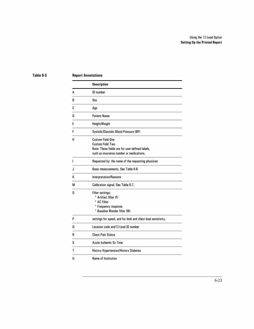
8VLQJ�WKH����/HDG�2SWLRQSetting Up the Printed Report
6-23
Table 6-5 Report Annotations
Description
$ ,'�QXPEHU
% 6H[
& $JH
' 3DWLHQW�1DPH
( +HLJKW�:HLJKW
) 6\VWROLF�'LDVWROLF�%ORRG�3UHVVXUH��%3�
+ &XVWRP�)LHOG�2QH&XVWRP�)LHOG�7ZR1RWH��7KHVH�ILHOGV�DUH�IRU�XVHU�GHILQHG�ODEHOV��VXFK�DV�LQVXUDQFH�QXPEHU�RU�PHGLFDWLRQV�
, 5HTXHVWHG�E\��WKH�QDPH�RI�WKH�UHTXHVWLQJ�SK\VLFLDQ
- %DVLF�PHDVXUHPHQWV��6HH�7DEOH����
. ,QWHUSUHWDWLRQ�5HDVRQV�
0 &DOLEUDWLRQ�VLJQDO��6HH�7DEOH�����
2 )LOWHU�VHWWLQJV� �$UWLIDFW�ILOWHU��)� �$&�)LOWHU �)UHTXHQF\�UHVSRQVH �%DVHOLQH�:DQGHU�ILOWHU��:�
3 VHWWLQJV�IRU�VSHHG��DQG�IRU�OLPE�DQG�FKHVW�OHDG�VHQVLWLYLW\�
4 /RFDWLRQ�FRGH�DQG���/HDG�,'�QXPEHU�
5 &KHVW�3DLQ�6WDWXV
6 $FXWH�,VFKHPLF�6[�7LPH
7 +LVWRU\�+\SHUWHQVLRQ�+LVWRU\�'LDEHWHV
8 1DPH�RI�,QVWLWXWLRQ

8VLQJ�WKH����/HDG�2SWLRQSetting Up the Printed Report
6-24
Basic Measurements
The basic measurements table gives standard interval and duration measurements in milliseconds, and limb lead axis measurements in degrees. These are representative values for the dominant beat pattern in the ECG.
Table 6-6 Basic Measurements
Item Description Units
5$7( +HDUW�UDWH EHDWV�SHU�PLQXWH
35 35�LQWHUYDO PLOOLVHFRQGV
456' 456�GXUDWLRQ PLOOLVHFRQGV
47 47�LQWHUYDO PLOOLVHFRQGV
47& 47�LQWHUYDO�FRUUHFWHG�IRU�UDWH PLOOLVHFRQGV
3 )URQWDO�3�D[LV GHJUHHV
456 )URQWDO�PHDQ�456�D[LV GHJUHHV
7 )URQWDO�7�D[LV GHJUHHV

8VLQJ�WKH����/HDG�2SWLRQSetting Up the Printed Report
6-25
Calibration Signals
The following table shows how the height of the calibration pulse indicates ECG sensitivity.
Report Examples
The following figures illustrate ECG report formats with standard adult interpretation.
Table 6-7 Calibration Signals
ECG Size (mm/mV)Calibration Pulse
Display Label Limb LeadsV-leadsV1 - V6
12-Lead
��� � �
����ô9 � ���
��� �� ��
����ô9 �� �
��� �� ��
����ô9 �� ��
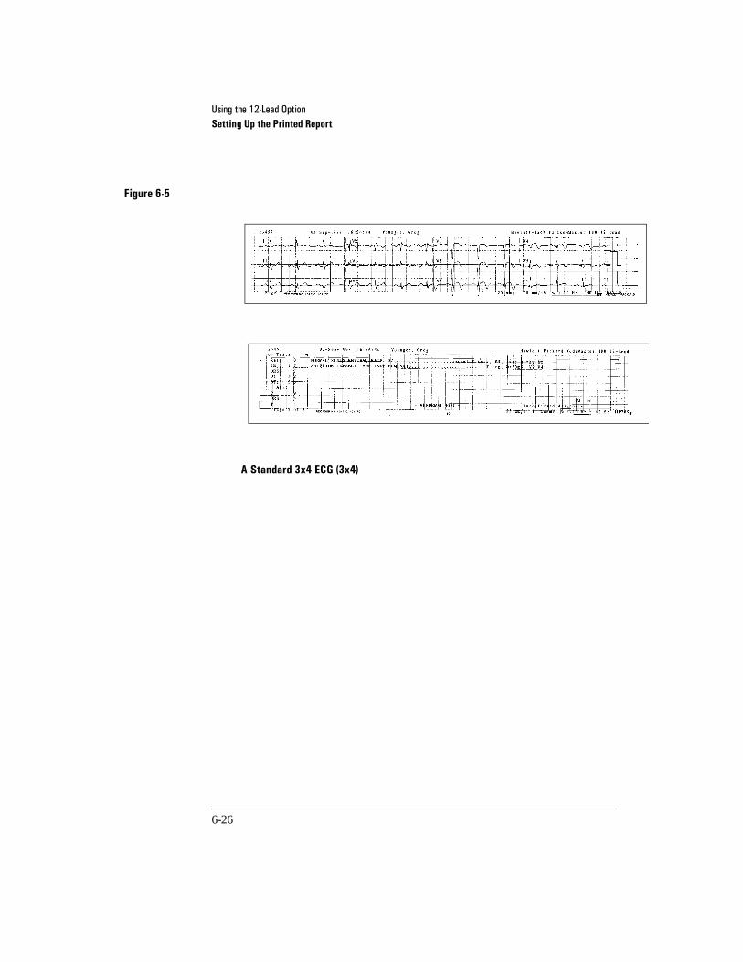
8VLQJ�WKH����/HDG�2SWLRQSetting Up the Printed Report
6-26
Figure 6-5
A Standard 3x4 ECG (3x4) 6-5

8VLQJ�WKH����/HDG�2SWLRQSetting Up the Printed Report
6-27
Figure 6-6
3x4 ECG with One Rhythm Strip (3x4, 1R) 6-6
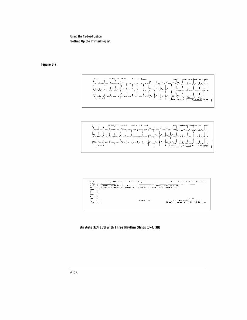
8VLQJ�WKH����/HDG�2SWLRQSetting Up the Printed Report
6-28
Figure 6-7
An Auto 3x4 ECG with Three Rhythm Strips (3x4, 3R) 6-7

8VLQJ�WKH����/HDG�2SWLRQUsing the 12-Lead Main Menu
6-29
6Using the 12-Lead Main Menu
When the 12-Lead first powers on, the initialization screen briefly appears as follows:
The system displays a message requesting that you attach the 12-Lead patient cable:
Hewlett-Packard CodeMaster 100 12-LeadM2475 English
© 1989, 1998 Hewlett-Packard Co.
Attach the HP 12-Lead ECG cable to take a 12-Lead
3x4 1.0 PulseFormat Size Line
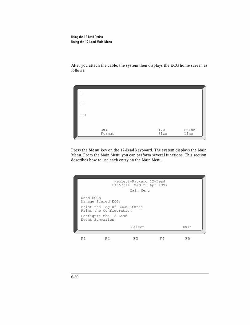
8VLQJ�WKH����/HDG�2SWLRQUsing the 12-Lead Main Menu
6-30
After you attach the cable, the system then displays the ECG home screen as follows:
Press the Menu key on the 12-Lead keyboard. The system displays the Main Menu. From the Main Menu you can perform several functions. This section describes how to use each entry on the Main Menu.
I
II
III
3x4 1.0 PulseFormat Size Line
Send ECGsManage Stored ECGs
Print the Log of ECGs StoredPrint the Configuration
Configure the 12-LeadEvent Summaries
Select Exit
Hewlett-Packard 12-Lead04:53:44 Wed 23-Apr-1997
Main Menu
F1 F2 F3 F4 F5

8VLQJ�WKH����/HDG�2SWLRQUsing the 12-Lead Main Menu
6-31
Sending ECGs
One or more Stored ECGs can be "Sent" at a time. This is useful for sending ECGs to an HP TraceMaster ECG Management System for long term archival.Stored ECGs appear in this screen. The most recent ECG will appear at the top of the ECG list.
Stored ECGs can be selected and sent in three different ways.
•Highlight the desired ECG by using the Arrow button on the keypad. Once the ECG is highlighted, push the "Send ECGs" soft key. This will take you to the Telephone Directory. Highlight the site for which you want the ECG to be sent and push the "Send" soft key.
•If more than one ECG is to be sent, simply highlight a desired ECG as described above, and then push the "Select" soft key to select that ECG. Once an ECG has been selected, a "*" will appear next to it indicating that it has been selected. Additional ECGs can be selected in the same manner. After ECGs have been selected, choose the "Send" soft key.
•All stored ECGs can be selected at once by choosing the "Select All" soft key. This is a quick and convenient way to select and send all old ECGs, if desired.
Send ECGs (2 ECGs Stored)Screen 1 of 1
Name/ID Time and Date*Frank SmithID: 12345678 10:02 10-Apr-97
Charlotte WebID: 87654321 10:00 10-Apr-97
=Sent *=SelectedSelect Send
Select All ECGs Exit
F1 F2 F3 F4 F5

8VLQJ�WKH����/HDG�2SWLRQUsing the 12-Lead Main Menu
6-32
Managing Stored ECGs
In this screen, one or more Stored ECGs can be managed at a time. Once selected, ECGs can be Deleted, Printed, or Edited.
To print or edit a stored ECG:
Highlight the desired ECG by using the Arrow button on the keypad. Once the ECG is highlighted, choose the soft key function that you want for managing the ECG.
To print or delete one or more stored ECG(s):
You can select more than one ECG at a time. Simply highlight a desired ECG as above, and then push the "Select" soft key to select that ECG. Once an ECG has been selected, a "*" will appear next to it indicating that it has been selected. Additional ECGs can be selected in the same manner. After ECGs have been selected, choose the soft key function that you want for managing the ECGs.
Manage Stored ECGs (2 ECGs Stored)Screen 1 of 1
Name/ID Time and Date*Frank SmithID: 12345678 10:02 10-Apr-97
Charlotte WebID: 87654321 10:00 10-Apr-97
=Sent *=Selected
Edit Print Delete Select I.D. Exit
F1 F2 F3 F4 F5

8VLQJ�WKH����/HDG�2SWLRQUsing the 12-Lead Main Menu
6-33
Printing the Log of ECGs Stored
A list of all Stored ECGs can be printed on the printer. The printed ECG Log report includes the date, time, ID, Patient Name, and ECG report format.
Print the Configuration
When you select this entry, the system will print the current configuration.
Send Event Summaries
This functionality will transmit the Event Summary to an event summary host.

8VLQJ�WKH����/HDG�2SWLRQHP CodeMaster 100 and 12-Lead Option Interactions
6-34
6HP CodeMaster 100 and 12-Lead Option Interactions
This section describes the interactions that occur between the HP CodeMaster 100 and the 12-Lead option.
•If the HP CodeMaster 100 is reset or a shock is delivered while the 12-Lead option is attempting to acquire or store an ECG, 12-Lead operation is sus-pended and the ECG will be lost (with no recovery).
The HP CodeMaster 100 resets when the following occurs:-delivering a shock-changing modes (manual to shock advisory)-changing the battery
To resume transmitting after the unit is reset, select the ECG from the Send ECGs Menu and press Send.
•The 12-Lead option does not operate while the HP CodeMaster 100 is set to Shock Advisory mode.
•Low Battery information from the HP CodeMaster 100 displays on the 12-Lead screen.
•When the language option is changed in SETUP MENU 1 on the HP Code-Master 100, the 12-Lead user interface will display the new language upon the next power on .
•Since the HP CodeMaster 100 and 12-Lead option share the 50mm recorder, any action which would normally cause the HP CodeMaster 100 to print will interrupt any report printing on the 12-Lead. Press Try Again to resume 12-Lead printing.

7-1
7Performing Synchronized Cardioversion
This chapter contains information about performing synchronized cardioversion on a patient with the HP CodeMaster 100.
Refer to “Preparing the Patient” on page 5-5 for information on patient preparation.
7Performing Cardioversion
Treatment for certain arrhythmias requires synchronizing a defibrillator shock with the ECG’s R-wave. It is essential that this R-wave is detected to avoid inducing ventricular fibrillation.
Monitoring During Cardioversion
Using an External Monitor
Whenever possible, Hewlett-Packard recommends that you perform synchronized cardioversion procedures while directly monitoring the patient through the multifunction defib electrodes or ECG leads inputs.
If you use an external monitor as the ECG source, ask your biomedical technician to verify that the CodeMaster 100 defibrillator and external monitor combination will deliver a synchronized shock within 60 ms of the peak of the R-wave. (See the HP M2475B CodeMaster 100 Portable Defibrillator/Monitor Service Manual for test procedure.) Use a 1 mV QRS complex with a QRS width of 40 ms. This performance cannot be guaranteed with all commercially available monitors.
WARNING

3HUIRUPLQJ�6\QFKURQL]HG�&DUGLRYHUVLRQPerforming Cardioversion
7-2
There are three ways to monitor ECG for synchronized cardioversion: use an external ECG monitor; connect ECG electrodes to the HP CodeMaster 100; or use multifunction defib electrodes.
External ECG monitor When the patient is already connected to bedside monitoring equipment, there is an external monitoring cable which plugs into the ECG Output jack of the bedside monitor and connects to the HP CodeMaster 100 ECG Input for monitoring. To use an external monitor, perform the following steps:
1 Select Lead I or Lead II on the HP CodeMaster 100.
2 Plug the cable into the external monitor ECG Output jack and plug the input end of the cable into the ECG input plug on the HP CodeMaster 100.
Using ECG electrodes with the HP CodeMaster 100 Use a patient cable connected to the patient and select Lead I, Lead II, or Lead III, choosing the best lead that displays a large QRS complex.
Using multifunction defib electrodes Use the electrode adapter cable (M2472A) and defib electrodes, selecting PADS as the ECG source.
3HUIRUPLQJ�6\QFKURQL]HG�&DUGLRYHUVLRQPerforming Cardioversion
7-3
Using Paddles for Performing Synchronized Cardioversion
To start cardioversion, perform the following steps.
1 Turn the Energy Select control to Monitor On.
2 Select the desired ECG lead by pressing Lead Select.
3 Press Sync once to place the HP CodeMaster 100 in Sync mode. The message SYNC appears on the display.
If you select paddles as the ECG source, the message USE LEADS will appear on the display. Although the HP CodeMaster 100 will allow synchronized shock in paddles ECG mode, leads mode is recommended. Artifact induced by moving the paddles may resemble an R-wave and trigger defibrillator shock.
You can perform cardioversion in Autogain mode. Always inspect the displayed ECG before delivering the counter shock. Verify that an R-wave marker (indi-cating shock point) appears only with each R-wave. If a marker dot does not appear, or if a marker dot is viewed on the T-wave segment of the ECG, follow these instructions:
•Adjust the ECG size by pressing ECG Size until the marker dot appears only with each R-wave.
•Select a different lead or adjust the electrode placement, if necessary, to improve ECG R-wave quality.
4 Select the desired energy level with the Energy Select control.
WARNING

3HUIRUPLQJ�6\QFKURQL]HG�&DUGLRYHUVLRQPerforming Cardioversion
7-4
Applying the Paddles
1 Prepare the paddles by performing the following steps:
a. Remove the paddles from their holders by grasping the handles and lifting straight up.
b. Holding both paddles in one hand, apply electrolyte medium to both paddle electrode surfaces.
To avoid the risk of electrical shock or burns, do not allow electrolyte medium to accumulate on your hands, the paddle handles, or the paddle electrodes on the patients chest.
Do not rub the electrode surfaces together to distribute the applied electrolyte medium. Placing the electrode surfaces together increases the risk of an accidental paddle-to-paddle discharge and may cause damage to the surface of the paddles.
2 Apply the paddles to the chest as follows.
a. Place the Sternum paddle to the right of the sternum just below the clavicle.
b. Place the Apex paddle on the chest just below and to the left of the left nip-ple, in the anterior-axillary line.
3 Rub the paddles lightly against the skin to distribute the electrolyte medium and increase the contact between the patient skin and the paddles.
To avoid the risk of burns to the patient, do not spread electrolyte medium between the paddle electrodes on the chest. The patient can be burned if the medium forms a path between the electrodes.
4 Apply 10 to 12 kg (22 - 25 lb.) of pressure per paddle. (Refer to the paddle con-tact indicator on the Sternum paddle to verify paddle contact.)
5 Press Charge on either the right (Apex) paddle or on the instrument front panel.
WARNING
CAUTION
WARNING

3HUIRUPLQJ�6\QFKURQL]HG�&DUGLRYHUVLRQPerforming Cardioversion
7-5
6 Wait for the Charge Done indicators.
If you must disarm the charged defibrillator (if counter shock is not needed), turn the Energy Select control to Monitor On. Any stored energy will be discharged internally and the available energy on the display will return to 0.
Resetting the Selected Energy Level
To increase or decrease the selected energy level after Charge has been pressed, move the Energy Select control to the new energy level, and wait for the Charge Done indicators.
Delivering the Synchronized Shock
To perform synchronized cardioversion:
1 Verify again that the ECG waveform is stable, and that a marker dot appears only with each R-wave of the cardiac cycle.
2 Briefly adjust paddle pressure and placement to optimize contact, as registered on the paddle contact indicator.
3 Depress both Shock ( ) buttons (one on each paddle) until shock occurs. The defibrillator will shock with the next detected R-wave.
4 If additional counter shocks are required, readjust the Energy Select control, and repeat the synchronized cardioversion procedure.
Depending on how the unit has been configured, it will either remain in the synchronized shock mode or it will return to defibrillator mode following a synchronized shock. Refer to Table 2-1 on page 2-11 for instructions on configuring the defibrillator for operation after synchronized cardioversion.
If the defibrillator does not shock, refer to “If the Defibrillator does not Deliver a Shock” on page 12-4.
NOTE
NOTE

3HUIRUPLQJ�6\QFKURQL]HG�&DUGLRYHUVLRQPerforming Cardioversion
7-6
Using Multifunction Defib Electrodes for Performing Synchronized Cardioversion
This section provides details for performing synchronized cardioversion with multifunction defib electrodes. Multifunction defib electrodes can be selected as the ECG source for cardioversion because they provide a reliable contact for monitoring.
Applying the Multifunction Defib Electrodes
1 Attach the electrode adapter cable (M2472A) to the defibrillator.
2 Attach the multifunction defib electrodes to the patient as instructed on the elec-trode package.
3 Connect the electrode cable connector to the electrode adapter cable. The elec-trodes are correctly connected when the locking ring is twisted, locking the ears of the connector to the adapter cable.
4 Turn the Energy Select control to Monitor On.
If the PADS OFF monitor message is displayed, check all patient connections.
5 Select pads as the ECG source by pressing Lead Select.
6 Press Sync once to place the HP CodeMaster 100 in Sync mode. The message SYNC will appear on the display.

3HUIRUPLQJ�6\QFKURQL]HG�&DUGLRYHUVLRQPerforming Cardioversion
7-7
You can perform cardioversion in Autogain mode. Always inspect the displayed ECG before delivering the counter shock. Verify that an R-wave marker (indi-cating shock point) appears only with each R-wave. If a marker dot does not appear, or if a marker dot is viewed on the T-wave segment of the ECG, follow these instructions:
•Adjust the ECG size by pressing ECG Size until the marker dot appears only with each R-wave.
•Adjust the placement of the multifunction defib electrodes to improve ECG R-wave quality.
7 Press Charge on the front panel of the HP CodeMaster 100.
8 Wait for the Charge Done indicators.
If you must disarm the charged defibrillator (if counter shock is not needed), turn the Energy Select control to Monitor On. Any stored energy will be discharged internally and the available energy on the display will return to 0.
Resetting the Selected Energy Level
To increase or decrease the selected energy level after you press Charge, move the Energy Select control to the new energy level. Wait for the Charge Done indicators.
Delivering the Synchronized Shock
To perform synchronized cardioversion refer to the following steps:
1 Verify again that the ECG waveform is stable and that a marker dot appears only with each R-wave of the cardiac cycle.
2 Depress both Shock buttons on the cable connector simultaneously until shock occurs. The defibrillator will shock with the next detected R-wave.
NOTE

3HUIRUPLQJ�6\QFKURQL]HG�&DUGLRYHUVLRQPerforming Cardioversion
7-8
3 If additional counter shocks are required, readjust the Energy Select control as necessary, and repeat the synchronized cardioversion procedure.
Depending on how the unit has been configured, the HP CodeMaster 100 will either remain in the synchronized shock mode or it will return to defibrillator mode following a synchronized shock. Refer to Table 2-1 on page 2-11 for instructions on configuring the defibrillator for operation after synchronized cardioversion.
If the defibrillator does not shock, refer to “If the Defibrillator does not Deliver a Shock” on page 12-4.
After Using the Defibrillator
If you want to print an Event Summary now, press Review. (See “Printing the Event Summary Record” on page 5-12.) After you use the defibrillator, perform the following steps to prepare the defibrillator for its next use.
o Clean all paddles, controls, and cables. Visually check the patient cables, paddles, paddles cables, and electrode adapter cables for wear, insulation nicks, and other damage. Refer to the Chapter 13, ”Maintenance” for additional information.
o Turn on the HP CodeMaster 100. If the instrument displays LOW BATTERY, replace the battery pack with a charged battery.
o Perform the test described in “Delivered Energy and Shock Button Functional Test” on page 13-3.
o Turn the Energy Select control to Off and return the HP CodeMaster 100 to its storage location.
o Check that sufficient recorder paper and electrolyte medium or multifunction defib electrodes are available for the next use of the defibrillator.
o Make sure that a battery is in the battery support system being charged. See “Charging the Battery” on page 13-14.
NOTE

8-1
8Pacing
This chapter contains instructions for using the pacer. For more concise details regarding noninvasive pacing, refer to HP CodeMaster Series Defibrillator/Monitor Pacing Application Note.
8What is Noninvasive Transcutaneous Pacing?
Noninvasive transcutaneous pacing is a technique of electrically stimulating the heart externally through a set of electrodes. Pacing is required when the heart’s own conduction system slows dangerously.
The HP CodeMaster 100 with the pacer can perform external transcutaneous pacing. The pacer provides demand (synchronous) and fixed (asynchronous) pacing modes. The patient is connected to the pacer by multifunction defib electrodes. The patient can be paced and defibrillated through the same set of electrodes.

3DFLQJPacer Operating Controls
8-2
8Pacer Operating Controls
The pacer operating controls on the HP CodeMaster 100 are detailed in “Pacer Operating Controls” on page 1-11.
While pacing, avoid touching the gelled area of the multifunction defib electrodes or the patient to prevent electrical shock.
Use only Hewlett-Packard recommended electrodes with the external pacer. The HP CodeMaster 100 delivers pacer pulses through a low-impedance multifunction defib electrode. The HP CodeMaster 100 does not pace effectively with high-impedance, pace-only electrodes.
Do not use the same defib electrodes for more than eight hours of continuous pacing.
8Using the Pacer
To use the pacer, perform the following steps:
1 Apply the multifunction defib electrodes as instructed on the package.
2 Attach the ECG monitoring electrodes as instructed in “Preparing the Leads for Monitoring” on page 5-3.
3 Attach the patient cable to the ECG Input connector of the HP CodeMaster 100.
4 Attach the patient cable leads to the ECG monitoring electrodes.
5 Attach the electrode adapter cable (M2472A) to the defibrillator output connec-tor. Pull the latch connector toward the front of the defibrillator to lock the con-nector in place.
WARNING

3DFLQJUsing the Pacer
8-3
6 Attach the multifunction defib electrodes to the electrode adapter cable. The electrodes are correctly connected when the locking ring is twisted, locking the ears of the connector to the adapter cable.
7 Turn the Energy Select control to the Monitor On position.
•If the message NO PADDLES is displayed, check that the pads adapter cable con-nector is properly seated and latched.
•If the message PADS OFF is displayed, check the electrodes connection to the patient and to the electrode adapter cable.
8 Press Pacer On to set up the pacer. Pacer parameters will now be displayed at the bottom of the display (PACER STOP, DEMAND MODE, 70 PPM 30 MA). The rate (ppm) and output (mA) settings for when the pacer is turned on can be selected in Setup Menu 1. The original rate and output settings from the factory are 70 ppm and 30mA. The pacer is always in Demand mode when it is turned on.
At this point, no pacer pulses are being delivered to the patient. The pacer must be started before the pacer pulses are delivered at the selected rate (ppm) and output (mA).
If the pacing mode is ON and the configuration settings are altered, the user can move in and out of pacing (provided the defibrillator is not shut off) and the settings will not revert back to the factory default. For example, if the user is pacing, then shocking, then pacing again, the pacing mode will return to the last pacing configuration before shocking. If the defibrillator is turned off after pacing is configured, then when pacing is turned on again, the settings will return to the factory default.
9 Press Lead Select to select the best lead for monitoring while pacing. You can only select Leads as the ECG source when the pacer is on.
•If LEADS OFF is displayed, check all patient cable connections.
10 Press Rate to adjust the rate. The monitor displays the selected rate (ppm).
11 Press Mode to select the pacing mode (demand mode/fixed mode). The monitor displays the selected mode.
NOTE

3DFLQJUsing the Pacer
8-4
Demand Mode Pacing When in demand mode, the pacer will only deliver pacer pulses when the patient’s heart rate is lower than the selected pacer rate.
Fixed Mode Pacing When in fixed mode, the pacer will deliver pacer pulses at the selected pacer rate.
Use demand pacing mode whenever possible. Use fixed pacing mode (asynchronous) for cases when reliably monitoring the patient is impractical. For example, use fixed mode when there is motion artifact or other ECG noise that makes R-wave detection unreliable.
12 Press Start/Stop to start pacing. The monitor displays the message PACING as well as the selected mode, rate, and output.
The pacer will not start pacing if there is a problem with either the multifunction defib electrode connections or the ECG monitoring electrode connections. If there is a problem with the multifunction defib electrode connection, the mes-sage ATTACH PADS will be displayed briefly when you press Start/Stop.
13 Verify that the pacer pulses are well positioned in the diastole.
14 Increase output (mA) by pressing Output until the beat is captured. Selecting an alternate lead can help you determine capture.
WARNING

3DFLQJUsing the Pacer
8-5
15 To set the lowest possible output level to capture, decrease the current by decre-ments of 5 mA by pressing Output.
If the monitoring ECG lead falls off while pacing in demand mode, the pacer will stop delivering pulses and the messages PACER STOP and LEADS OFF will appear. To resume pacing, reattach the lead and press Start/Stop.
Pacing in fixed mode does not require ECG leads to be attached for the pacer to deliver pulses.
If a multifunction defib electrode comes off during pacing, the pacer will stop delivering pulses and the messages PACER STOP and PADS OFF will appear. To resume pacing, reattach the electrode and press Start/Stop.
NOTE

3DFLQJUsing the Pacer
8-6
HR meters and HR alarms function during pacing, but they can be unreliable. The HR meter attempts to count QRS activity in both demand and fixed pacing modes. Observe the patient closely while pacing. Do not rely on heart rate alarms or the indicated heart rate as a measure of the patient’s perfusion status.
If the battery runs out during pacing and you replace it with a charged battery, the instrument may no longer be in pacing mode. To resume pacing, press Pacer On and Start/Stop.
WARNING
NOTE

3DFLQJUsing the Pacer
8-7
Defibrillation During Pacing
If the patient must be defibrillated during pacing, perform the following steps.
1 Set the desired energy level with the Energy Select control.
2 Press Charge. The defibrillator will automatically turn off the pacer and start charging. The pacer status messages will be cleared and replaced with the defibrillator delivered energy display.
3 Call out "Clear!" to alert personnel to stand away from the patient.
4 Wait for the Charge Done Indicators.
5 Simultaneously press and briefly hold both Shock ( ) buttons, located on the cable connector. The shock will be delivered through the multifunction defib electrodes.
After the shock, the pacer remains off. Press the Start/Stop button to resume pacing if it is required.

3DFLQJUsing the Pacer
8-8

9-1
9SpO2 Monitoring
This chapter explains how to use the pulse oximeter feature of the HP CodeMaster 100.
SpO2 monitoring gives information on both cardiac and respiratory systems, and details of oxygen transportation in the body. It is widely used because it is non-invasive, continuous, easily applied and painless.
The quality of SpO2 measurements depends on careful application of the sensor. Read the following section, to understand the importance of sensor application. For more detailed information, refer to Understanding Pulse
Oximetry Guide.
You can use the SpO2 monitor with sensors made by other manufacturers as well as with Hewlett-Packard sensors. For a list of approved sensors, see the Sensor Guide.
9Understanding Pulse Oximetry
This section provides a brief description of SpO2.
SaO2 and SpO2
Hewlett-Packard is adopting the convention of referring to the SpO2 parameter. Previously it was referred to as SaO2.
SaO2 is the term used to indicate the oxygen saturation of arterial blood.
SpO2 is the term used to indicate the oxygen saturation of arterial blood as
measured by pulse oximetry.
NOTE
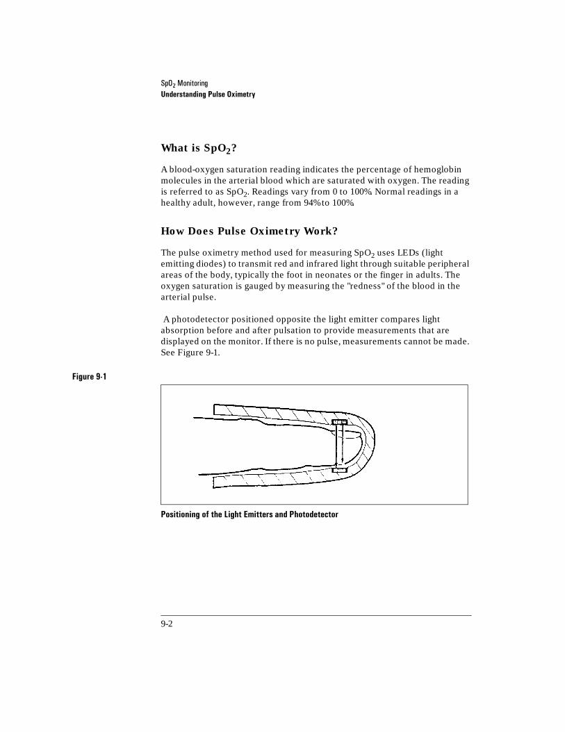
6S2��0RQLWRULQJUnderstanding Pulse Oximetry
9-2
What is SpO2?
A blood-oxygen saturation reading indicates the percentage of hemoglobin molecules in the arterial blood which are saturated with oxygen. The reading is referred to as SpO2. Readings vary from 0 to 100%. Normal readings in a healthy adult, however, range from 94% to 100%.
How Does Pulse Oximetry Work?
The pulse oximetry method used for measuring SpO2 uses LEDs (light emitting diodes) to transmit red and infrared light through suitable peripheral areas of the body, typically the foot in neonates or the finger in adults. The oxygen saturation is gauged by measuring the "redness" of the blood in the arterial pulse.
A photodetector positioned opposite the light emitter compares light absorption before and after pulsation to provide measurements that are displayed on the monitor. If there is no pulse, measurements cannot be made. See Figure 9-1.
Figure 9-1
Positioning of the Light Emitters and Photodetector 9-1

6S2��0RQLWRULQJSpO2 Operating Controls
9-3
For accurate measurements, the following conditions must apply:
o All transmitted light must pass through the extremity to the detector.
o The patient must have at least a minimum pulse.
o The light emitter and the photodetector must be opposite each other.
9SpO2 Operating Controls
The SpO2 operating controls on the HP CodeMaster 100 SpO2 Operating Controls are detailed in “SpO2 Operating Controls” on page 1-13
9Patient Monitor Using SpO2
Sensor Types
There are three types of sensors:
Disposable 'LVSRVDEOH�VHQVRUV�VKRXOG�EH�XVHG�RQFH�RQO\�DQG�WKHQ�GLVFDUGHG��+RZHYHU��WKH\�FDQ�EH�UHORFDWHG�WR�D�GLIIHUHQW�DSSOLFDWLRQ�VLWH�RQ�WKH�SDWLHQW�LI�WKH�ILUVW�ORFDWLRQ�GRHV�QRW�JLYH�WKH�GHVLUHG�UHVXOWV��'LVSRVDEOH�VHQVRUV�PXVW�QRW�EH�UHXVHG�RQ�GLIIHUHQW�SDWLHQWV��
Semi-Disposable 6HPL�GLVSRVDEOH�VHQVRUV�FDQ�EH�UHXVHG��EXW�WKH�DGKHVLYH�ZUDS�PXVW�EH�GLVFDUGHG�DIWHU�HDFK�XVH��6HPL�GLVSRVDEOH�VHQVRUV�DUH�UHFRPPHQGHG�IRU�VLQJOH�SDWLHQW�XVH�RQO\��
Reusable 5HXVDEOH�VHQVRUV�FDQ�EH�UHXVHG�RQ�GLIIHUHQW�SDWLHQWV��
6S2��0RQLWRULQJPatient Monitor Using SpO2
9-4
Using SpO2
Before you start SpO2 monitoring, refer to the following steps:
1 Estimate the patient’s weight and determine the best site for the sensor.
2 Use the Sensor Guide to select the correct type and size of sensor for the identified location.
3 Prepare the sensor:
•Disposable: Remove protective backing.
•Semi-Disposable: Apply a new adhesive wrap to the sensor.
4 Apply the sensor to the identified location.
5 Connect the sensor to the monitor. To connect sensors from other manu-facturers, use the HP M1900B Connector Cable.
Apply the Sensor to the Patient
Hewlett-Packard supports the use of many sensors. Use the Sensor Guide to find the sensor which is best for your case. Follow the manufacturer’s guidelines for applying and using the sensor.
Applying the Reusable Sensor
Push the sensor over the fingertip so the cable lies on the back of the hand. Secure the cable to the wrist with the wrist-strap supplied. Make sure the finger is not pinched in the end of the sensor. See Figure 9-2. This ensures that the light sources in the sensor lie over the base of the fingernail, giving the best measurement results. If the sensor is not in the correct position, inaccurate readings result. In extreme cases, the instrument displays dashes instead of an SpO2 reading. When correctly positioned, the end of the
finger just touches the end of the sensor.
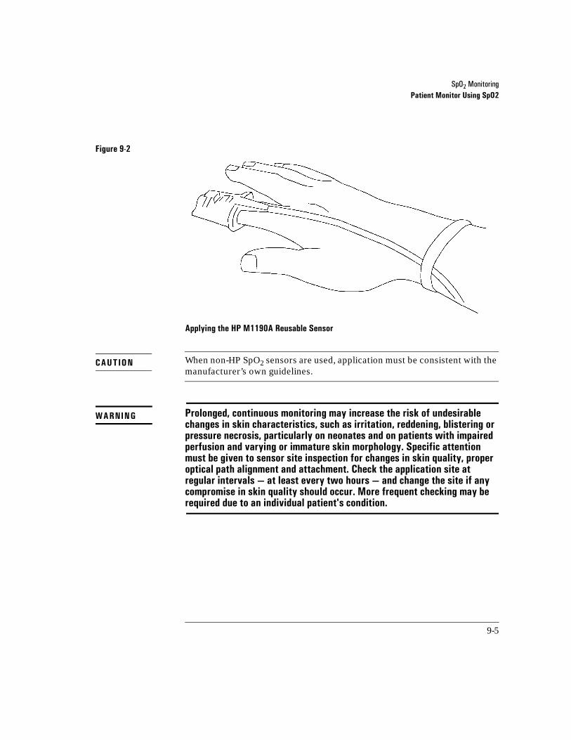
6S2��0RQLWRULQJPatient Monitor Using SpO2
9-5
Figure 9-2
Applying the HP M1190A Reusable Sensor 9-2
When non-HP SpO2 sensors are used, application must be consistent with the manufacturer’s own guidelines.
Prolonged, continuous monitoring may increase the risk of undesirable changes in skin characteristics, such as irritation, reddening, blistering or pressure necrosis, particularly on neonates and on patients with impaired perfusion and varying or immature skin morphology. Specific attention must be given to sensor site inspection for changes in skin quality, proper optical path alignment and attachment. Check the application site at regular intervals — at least every two hours — and change the site if any compromise in skin quality should occur. More frequent checking may be required due to an individual patient's condition.
CAUTION
WARNING

6S2��0RQLWRULQJPatient Monitor Using SpO2
9-6
Troubleshooting Sensor Application
Failure to apply the sensor properly may cause incorrect measurement of arterial oxygen saturation.
Do not use a damaged sensor or one with exposed electrical circuits.
Patient Movement
Make sure that the application site chosen does not move excessively, which may adversely affect the performance of the sensor. You may have to replace the sensor to ensure good adhesion, or you may have to choose another application site.
Inspecting the Application Site
Inspect the SpO2 sensor site at least once every 2 hours to ensure adhesion, skin integrity, and correct alignment of the light emitter and photodetector. Should alterations of skin integrity occur, remove the sensor and reapply at another recommended site. Avoid application of the sensor to edematous or fragile tissue. Check circulation distal to the sensor site routinely.

6S2��0RQLWRULQJPatient Monitor Using SpO2
9-7
Circulation at Application Site
•Wrapping the tape too tightly, or using supplemental tape, can cause venous pulsations that could potentially lead to inaccurate saturation measure-ments.
•Avoid wrapping the adhesive too tightly and do not use additional tape to secure the sensor. High positive intrathoracic airway pressures, valsalva maneuvers, or other consequences of impaired venous return may also cause venous pulsations.
•Only use adhesive wraps recommended by Hewlett-Packard.
•Avoid placing the SpO2 sensor on any extremity with an arterial catheter, blood pressure cuff, or intravascular venous infusion line.
Connecting the Sensor to the Instrument
When you have applied the sensor to the patient, plug the disposable and semi-disposable sensors into the connector cable and plug this cable into the SpO2 socket on the lower right of the HP CodeMaster 100. Plug the HP M1190A sensor directly into the SpO2 socket of the HP CodeMaster 100. The plug is keyed and is color-coded blue to distinguish it from the white ECG socket. See Figure 9-3.
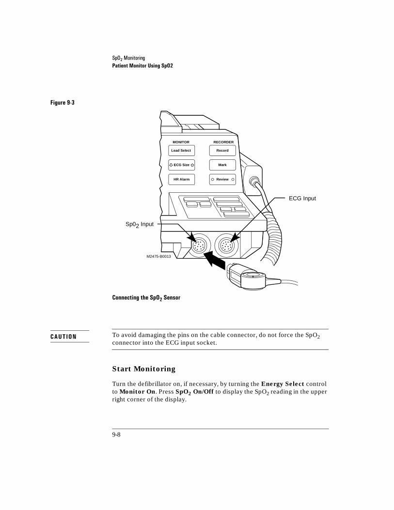
6S2��0RQLWRULQJPatient Monitor Using SpO2
9-8
Figure 9-3
Connecting the SpO2 Sensor 9-3
9-3
To avoid damaging the pins on the cable connector, do not force the SpO2 connector into the ECG input socket.
Start Monitoring
Turn the defibrillator on, if necessary, by turning the Energy Select control to Monitor On. Press SpO2 On/Off to display the SpO2 reading in the upper right corner of the display.
MONITOR RECORDER
Lead Select
ECG Size
HR Alarm
Record
Mark
Review
M2475-B0013
ECG Input
Sp02 Input
S S
CAUTION
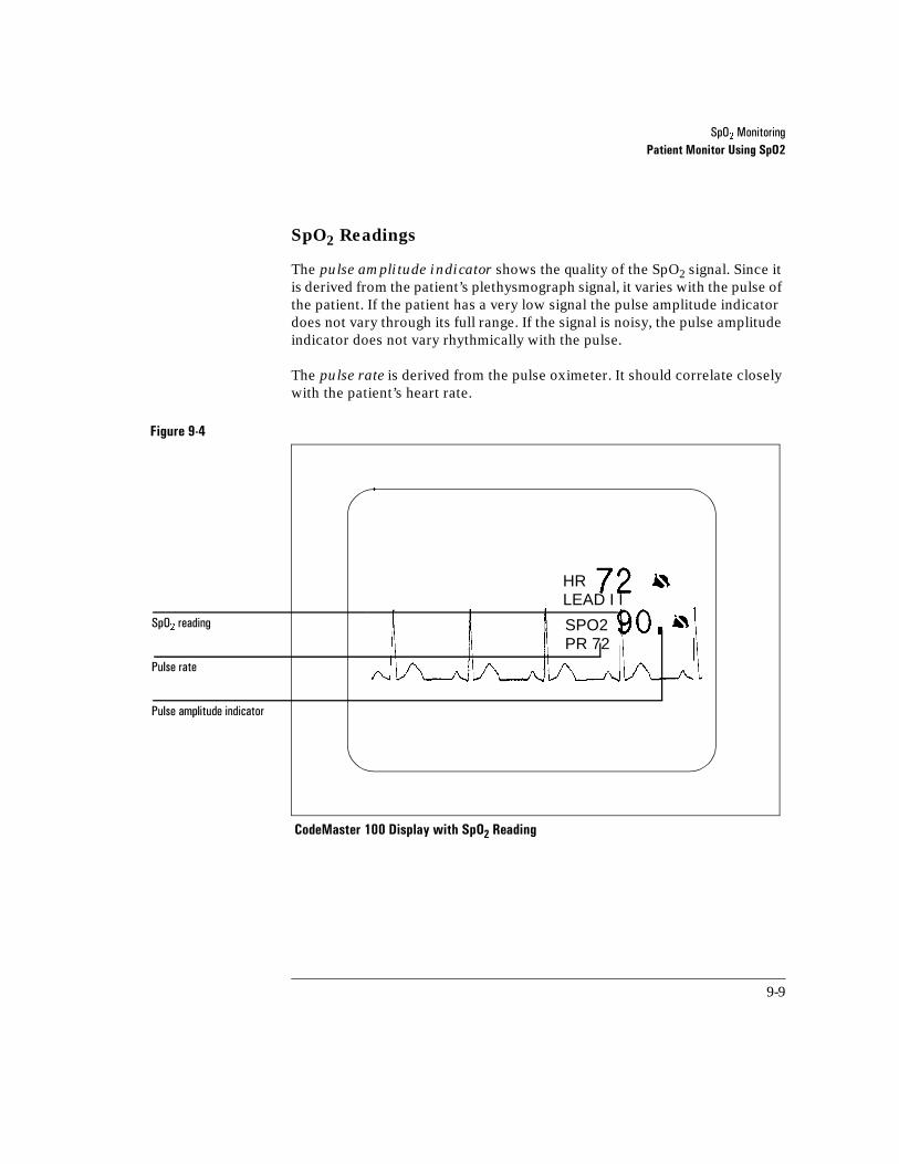
6S2��0RQLWRULQJPatient Monitor Using SpO2
9-9
SpO2 Readings
The pulse amplitude indicator shows the quality of the SpO2 signal. Since it is derived from the patient’s plethysmograph signal, it varies with the pulse of the patient. If the patient has a very low signal the pulse amplitude indicator does not vary through its full range. If the signal is noisy, the pulse amplitude indicator does not vary rhythmically with the pulse.
The pulse rate is derived from the pulse oximeter. It should correlate closely with the patient’s heart rate.
Figure 9-4
CodeMaster 100 Display with SpO2 Reading 9-4
6S2��UHDGLQJ
3XOVH�DPSOLWXGH�LQGLFDWRU
3XOVH�UDWH
HRLEAD I I
SPO2PR 72
6S2��0RQLWRULQJSpO2 Alarms
9-10
9SpO2 Alarms
Activating SpO2 Alarms
There are three preset high/low SpO2 alarm limits: 100/90, 100/85 and 100/80. Press SpO2 alarm repeatedly to cycle through the alarm options and the no-alarm option. Stop when you see the alarm you would like to choose and
after three seconds that alarm will take effect. A symbol replaces the limits to show that the alarm is active. To review the limit set, press SpO2
alarm.
If the SpO2 level falls below the low alarm limit, an alarm sounds and the violated limit is highlighted.
SpO2 alarms are automatically turned off when you press Charge.
Deactivating SpO2 Alarms
Press SpO2 alarm. The symbol to the right of the SpO2 display
indicates that the alarms are off.
Recorder Output
After an alarm event, the recorder prints a strip. The bottom of the strip shows the alarm violation, and the top of the strip shows the SpO2 reading.
You may print an event summary record, which contains SpO2 information, as described in “Printing the Event Summary Record” on page 5-12.
NOTE

10-1
10Transmitting Data from the 12-Lead Option
This chapter provides instructions for transmitting 12-Lead ECGs and Event Summaries using the 12-Lead option of the HP CodeMaster 100. You can transmit using a landline or cellular phone with data link. The HP CodeMaster 100 supports data transmission from either an internal modem with an RJ11C connector (in US, UK, and Canada only) or an external modem via the RS-232 port. See Figure 10-1.
Figure 10-1
10-1
Modem Connections (Rear View of CodeMaster 100 with the 12-Lead Option) 10-1
The connection of an external modem or other telecommunications equipment may increase leakage currents beyond levels that are acceptable in a patient care environment. Always request that local safety personnel verify that multiple connected equipment comply with local requlatory standards before putting such equipment into service.
This product complies with United States, Canadian, and United Kingdom telecom regulatory standards for internal modems. See “Telecom Regulatory Information” on page -xv for further details.
PhoneConnector (RJ11C)
Modem/DirectConnector (DB9)
Rear Viewof 12-Lead Bezel
WARNING
NOTE

7UDQVPLWWLQJ�'DWD�IURP�WKH����/HDG�2SWLRQReceiving Devices
10-2
10Receiving Devices
The CodeMaster 100 with the 12-Lead option can transmit ECGs to:
• personal computer equipped with HP ECG Manager software (M1765A), referred to as ECG Manager gateway
• Group III facsimile machine
• HP TraceMaster ECG Management System (M1730A/B)
• HP PageWriter XLi cardiograph (M1700A)
• HP PageWriter 300pi/200i/200 cardiograph (M1770A, M1771A) equipped with storage and transmission option #A05
The CodeMaster 100 with the 12-Lead option can transmit the Event Summary to an event summary host.
Transmitting to an HP ECG Manager System HP ECG Manager running on a PC acts as a gateway or receiving station which receives, prints, stores, and forwards 12-Lead ECGs. This is the recommended platform for receiving and printing 12-Lead ECGs acquired and transmitted from the CodeMaster 100 defibrillator/monitor with 12-Lead option.
Transmitting to a Fax Machine You can send ECGs directly to standard fax machines. Transmitting directly to a fax machine does not require a special receiving station, however; transmitting ECGs direct to a fax machine has the following considerations and limitations:
-lengthens transmission time-cannot forward ECGs to HP TraceMaster-unable to store and retrieve ECGs elsewhere-is likely to be used for other business purposes
If the FAX machine is used for other business purposes, this increases the risk that it will be busy when emergency medical personnel are attempting to transmit an ECG.
NOTE

7UDQVPLWWLQJ�'DWD�IURP�WKH����/HDG�2SWLRQUsing Landline Communications
10-3
10Using Landline Communications
You can attach the CodeMaster 100 with the 12-Lead option to most landline RJ11C connectors (regular phone jack) using either the internal modem or a Hayes-compatible external modem. Note that the RJ11C cable running from the CodeMaster 100 that attaches to the phone jack is a standard phone cable and not provided with the HP CodeMaster 100.
Table 10-1 lists the landline communications capabilities.
Table 10-1 Landline Communications Capabilities
Sent From Via Destination
+3�&RGH0DVWHU��������/HDG 'LUHFWO\�ZLWK�/DQGOLQH )D[�0DFKLQH
+3�&RGH0DVWHU��������/HDG 'LUHFWO\ +3�3DJH:ULWHU���������L�����SL��;/L
+3�&RGH0DVWHU��������/HDG 'LUHFWO\ +3�(&*�7UDFH0DVWHU�(&*�0DQDJHU�6\VWHP
+3�&RGH0DVWHU��������/HDG (&*�0DQDJHU�5HFHLYLQJ�6WDWLRQ�DQG�*DWHZD\
)D[�0DFKLQH
+3�&RGH0DVWHU��������/HDG (&*�0DQDJHU�5HFHLYLQJ�6WDWLRQ�DQG�*DWHZD\
/DVHU�RU�,QNMHW�3ULQWHU
+3�&RGH0DVWHU��������/HDG (&*�0DQDJHU�5HFHLYLQJ�6WDWLRQ�DQG�*DWHZD\
+3�7UDFH0DVWHU�(&*�0DQDJHU�6\VWHP

7UDQVPLWWLQJ�'DWD�IURP�WKH����/HDG�2SWLRQUsing Landline Communications
10-4
Table 10-2 lists the direct communications capabilities via the RS 232 cable. HP recommends that you replace the serial cable on a regular basis based on used rate or at any time communications problems arise through the RS232 port, especially for units used outside of North America and the UK.
The internal modem will not work with a digital phone system or a digital Public Branch Exchange (PBX).
Figure 10-2 illustrates a standard landline connection using the internal modem. Figure 10-3 shows the HP CodeMaster 100 connecting to a landline connection using an external modem.
Table 10-2 Direct CommunicationsCcapabilities
Sent From Via Destination
+3�&RGH0DVWHU��������/HDG 'LUHFW�&DEOH +3�3DJH:ULWHU���������L�����SL��;/L
+3�&RGH0DVWHU��������/HDG 'LUHFW�&DEOH +3�7UDFH0DVWHU�(&*�0DQDJHU�6\VWHP
NOTE

7UDQVPLWWLQJ�'DWD�IURP�WKH����/HDG�2SWLRQUsing Landline Communications
10-5
Figure 10-2
Standard Landline Connection (Internal Modem) 10-2
10-2
Internal Modem
Example 1
Transmit Receiving SiteStandardPhone System
Example 2
Example 3
Example 4
RJ11CLandline Connection
Personal Computerrunning ECG Manager (M1765A) or EventSummary Host
HP TraceMasterECG ManagementSystem (M1730B)
HP PageWriter XLiCardiograph (M1700A)
Fax Machine
CodeMaster 100with 12-Lead Option

7UDQVPLWWLQJ�'DWD�IURP�WKH����/HDG�2SWLRQUsing Landline Communications
10-6
Figure 10-3
Standard Landline Connection (External Modem) 10-3
Example 1
Transmit Receiving SiteStandardPhone System
Example 2
Example 3
Example 4
Personal Computerrunning ECG Manager(M1765A) or EventSummary Host
HP TraceMasterECG ManagementSystem (M1730B)
HP PageWriter XLiCardiograph (M1700A)
Fax MachineLandline Connectionwith External ModemRS232 Port
ExternalModem
RJ11C
CodeMaster 100with 12-Lead Option
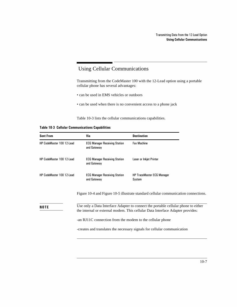
7UDQVPLWWLQJ�'DWD�IURP�WKH����/HDG�2SWLRQUsing Cellular Communications
10-7
10Using Cellular Communications
Transmitting from the CodeMaster 100 with the 12-Lead option using a portable cellular phone has several advantages: 10-3
• can be used in EMS vehicles or outdoors
• can be used when there is no convenient access to a phone jack
Table 10-3 lists the cellular communications capabilities.
Figure 10-4 and Figure 10-5 illustrate standard cellular communication connections.
Use only a Data Interface Adapter to connect the portable cellular phone to either the internal or external modem. This cellular Data Interface Adapter provides:
-an RJ11C connection from the modem to the cellular phone
-creates and translates the necessary signals for cellular communication
Table 10-3 Cellular Communications Capabilities
Sent From Via Destination
+3�&RGH0DVWHU��������/HDG (&*�0DQDJHU�5HFHLYLQJ�6WDWLRQ�DQG�*DWHZD\
)D[�0DFKLQH
+3�&RGH0DVWHU��������/HDG (&*�0DQDJHU�5HFHLYLQJ�6WDWLRQ�DQG�*DWHZD\
/DVHU�RU�,QNMHW�3ULQWHU
+3�&RGH0DVWHU��������/HDG (&*�0DQDJHU�5HFHLYLQJ�6WDWLRQ�DQG�*DWHZD\
+3�7UDFH0DVWHU�(&*�0DQDJHU�6\VWHP
NOTE
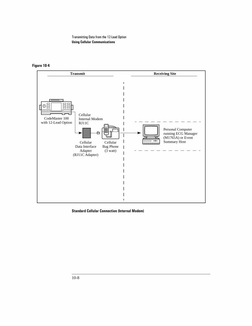
7UDQVPLWWLQJ�'DWD�IURP�WKH����/HDG�2SWLRQUsing Cellular Communications
10-8
Figure 10-4
Standard Cellular Connection (Internal Modem) 10-4
CellularInternal ModemRJ11C
Transmit Receiving Site
CellularData Interface
Adapter(RJ11C Adapter)
CellularBag Phone
(3 watt)
Personal Computerrunning ECG Manager (M1765A) or EventSummary Host
CodeMaster 100with 12-Lead Option
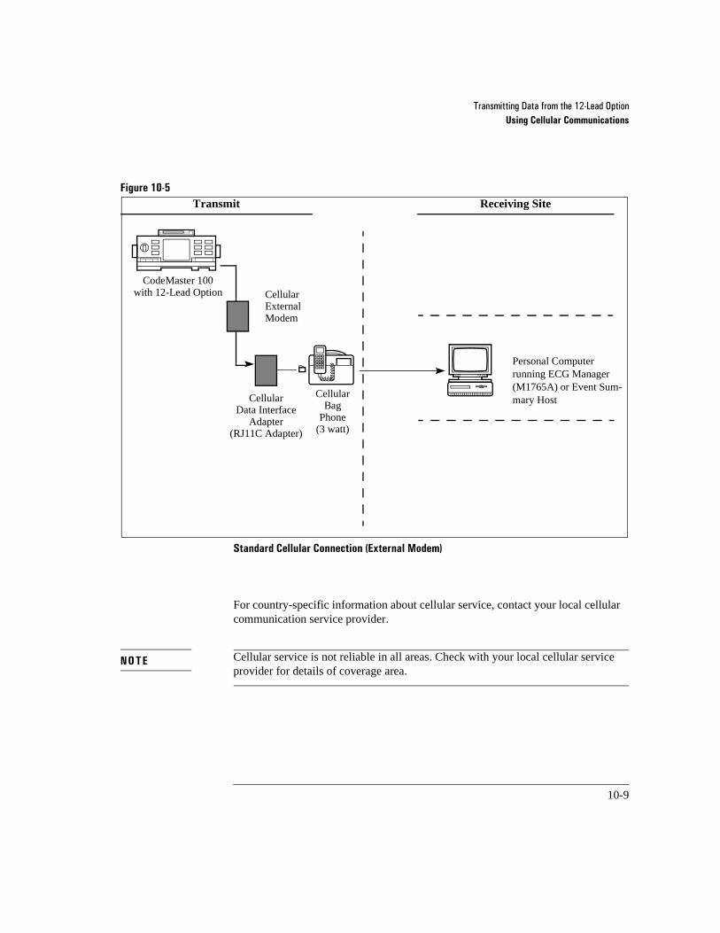
7UDQVPLWWLQJ�'DWD�IURP�WKH����/HDG�2SWLRQUsing Cellular Communications
10-9
Figure 10-5
Standard Cellular Connection (External Modem) 10-5
For country-specific information about cellular service, contact your local cellular communication service provider.
Cellular service is not reliable in all areas. Check with your local cellular service provider for details of coverage area.
Transmit Receiving Site
Personal Computerrunning ECG Manager (M1765A) or Event Sum-mary HostCellular
Data InterfaceAdapter
(RJ11C Adapter)
CodeMaster 100with 12-Lead Option
CellularBag
Phone(3 watt)
Cellular ExternalModem
NOTE

7UDQVPLWWLQJ�'DWD�IURP�WKH����/HDG�2SWLRQTransmitting a 12-Lead ECG
10-10
10Transmitting a 12-Lead ECG
To transmit an ECG:
1 Connect the cellular or landline connection cable to the modem.
2 Select the ECGs to send. Press the Send key or select Send ECGs from the Main Menu. The Send ECG Display appears:
Press F1 or F2 to highlight the ECGs. Press F4. The telephone directory appears.
Immediately after an ECG has been acquired and printed, it can be transmitted by pressing the Send button on the key pad. This will take you to the Telephone Directory screen. Once in the Telephone Directory, use the Arrow button on the key pad to highlight the destination for which you want to send the ECG and press the Send softkey or the Send button on the keypad again.
If Auto Send Acquired ECG has been enabled, then you will automatically be taken to the Telephone Directory after the ECG has been acquired and printed. Select the destination and press either the Send softkey or the Send button on the keypad.
Send ECGs (2 ECGs Stored)Screen 1 of 1
Name/ID Time and Date*Frank SmithID: 12345678 10:02 10-Apr-97
Charlotte StephensID: 87654321 10:00 10-Apr-97
=Sent *=SelectedSelect Send
Select All ECGs Exit
F1 F2 F3 F4 F5
NOTE

7UDQVPLWWLQJ�'DWD�IURP�WKH����/HDG�2SWLRQTransmitting a 12-Lead ECG
10-11
3 Choose the transmission destination for the ECG from the phone directory using the arrow keys. Use the F4 key to move through the different directory pages.
4 Press F2 or Send to transmit the ECG.
5 The system displays a message indicating successful transmission and then returns to the home display. If the ECG does not transmit, the system displays the Send ECGs screen.
If the system does not transmit the ECG successfully, refer to the section “Iden-tifying Transmission Problems” on page 12-17.
Press the STOP key to halt the transmission process.
For configuration information, refer to Chapter 2, ”Setup and Configuration”.
NOTE
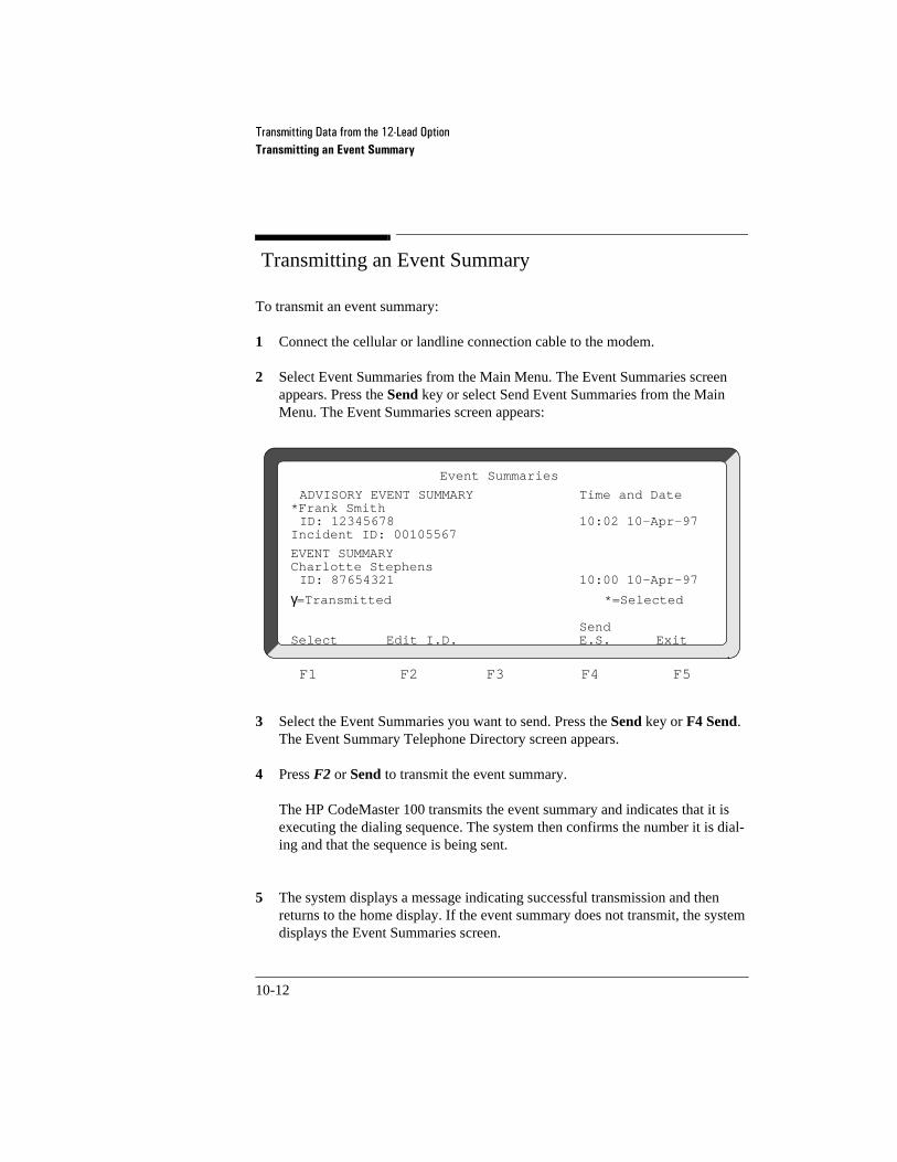
7UDQVPLWWLQJ�'DWD�IURP�WKH����/HDG�2SWLRQTransmitting an Event Summary
10-12
10Transmitting an Event Summary
To transmit an event summary:
1 Connect the cellular or landline connection cable to the modem.
2 Select Event Summaries from the Main Menu. The Event Summaries screen appears. Press the Send key or select Send Event Summaries from the Main Menu. The Event Summaries screen appears:
3 Select the Event Summaries you want to send. Press the Send key or F4 Send. The Event Summary Telephone Directory screen appears.
4 Press F2 or Send to transmit the event summary.
The HP CodeMaster 100 transmits the event summary and indicates that it is executing the dialing sequence. The system then confirms the number it is dial-ing and that the sequence is being sent.
5 The system displays a message indicating successful transmission and then returns to the home display. If the event summary does not transmit, the system displays the Event Summaries screen.
Event Summaries
ADVISORY EVENT SUMMARY Time and Date*Frank SmithID: 12345678 10:02 10-Apr-97
Incident ID: 00105567
EVENT SUMMARYCharlotte StephensID: 87654321 10:00 10-Apr-97
γ=Transmitted *=Selected
SendSelect Edit I.D. E.S. Exit
F1 F2 F3 F4 F5

7UDQVPLWWLQJ�'DWD�IURP�WKH����/HDG�2SWLRQTransmitting an Event Summary
10-13
If the system does not transmit the event summary successfully, refer to the sec-tion “Identifying Transmission Problems” on page 12-17.
Press the STOP key to halt the transmission process.
For configuration information, refer to Chapter 2, ”Setup and Configuration”.
NOTE

7UDQVPLWWLQJ�'DWD�IURP�WKH����/HDG�2SWLRQTransmitting an Event Summary
10-14

11-1
11Using Auxiliary Power
This section provides instructions for using auxiliary power sources with the HP CodeMaster 100 $&��+3�0����$��DQG�'&��+3�0����$��3RZHU�0RGXOHV�
11The AC Power Module
7KH�+3 0����$�$&�3RZHU�0RGXOH�LV�GHVLJQHG�WR�FKDUJH�WKH�EDWWHU\�LQVWDOOHG�LQ�WKH�+3�&RGH0DVWHU�����ZKLOH�WKH�EDWWHU\�LV�LQ�WKH�XQLW��7KH�$&�3RZHU�0RGXOH�FRQQHFWV�WR�DQ�$&�SRZHU�VRXUFH�WR�
���SURYLGH�FRQWLQXRXV�FKDUJLQJ�DQG�HQVXUH�WKDW�WKH�EDWWHU\�LV�UHDG\�IRU�XVH�ZKHQ�DQ�HPHUJHQF\�VLWXDWLRQ�DULVHV��
���SRZHU�WKH�+3�&RGH0DVWHU�����DQG�SURYLGH�IRU�ORQJ�WHUP�PRQLWRULQJ�ZLWK�RXW�WKH�QHHG�WR�FKDQJH�WKH�EDWWHU\�
Using the AC Power Module
To use the AC power module:
�� 3OXJ�WKH�$&�3RZHU�0RGXOH�SRZHU�FRUG�LQWR�DQ�$&�SRZHU�VRXUFH��9HULI\�WKDW�WKH�SRZHU�LQGLFDWRU�OLJKWV�XS�WR�VKRZ�WKDW�SRZHU�LV�VXSSOLHG�WR�WKH�PRGXOH��6HH�)LJXUH�������
�� &RQQHFW�WKH�$&�3RZHU�0RGXOH�GHILEULOODWRU�LQWHUIDFH�FDEOH�WR�WKH�+3�&RGH0DVWHU������7R�GR�VR��SRVLWLRQ�WKH�FDEOH�ZLWK�WKH�UHG�GRW�RQ�WKH�FRQQHFWRU�IDFLQJ�GRZQ�DQG�LQVHUW�WKH�FRQQHFWRU�LQWR�WKH����YROW�UHFHSWDFOH�
�� &KHFN�WKDW�WKH� �OLJKW�DSSHDUV�RQ�WKH�+3�&RGH0DVWHU������6HH�
)LJXUH��������,I�D�EDWWHU\�LV�LQVWDOOHG�LQ�WKH�+3�&RGH0DVWHU������DOVR�YHULI\�WKDW�WKH�FKDUJLQJ�LQGLFDWRU�OLJKWV�XS�RQ�WKH�$&�3RZHU�0RGXOH�
Battery technology used in this device still requires maintenance. The power module will not cycle/recondition batteries. Refer to Chapter 13, ”Maintenance”.
H[W�SRZHU
WARNING

8VLQJ�$X[LOLDU\�3RZHUThe AC Power Module
11-2
Indicators
Figure 11-1
$&�3RZHU�0RGXOH�,QGLFDWRUV 11-1
Charging Indicator
The charging indicator appears when the battery is installed in the HP CodeMaster 100 and the battery is being charged.
Power Indicator
The power indicator lights up when power is supplied to the AC Power Module.
SRZHU�LQGLFDWRUFKDUJLQJ�LQGLFDWRU
8VLQJ�$X[LOLDU\�3RZHUUsing the DC External Power Module
11-3
11Using the DC External Power Module
The HP M2478A external power module is a 12-Volt DC power source for the HP CodeMaster 100. This module is designed specifically for emergency vehicles with 12 Volt electrical systems. With this module, your vehicle’s 12 Volt system can power the HP CodeMaster 100, saving the defibrillator/monitor battery for remote use. Additionally, the HP CodeMaster 100 battery is recharged when it is attached to the external power module.
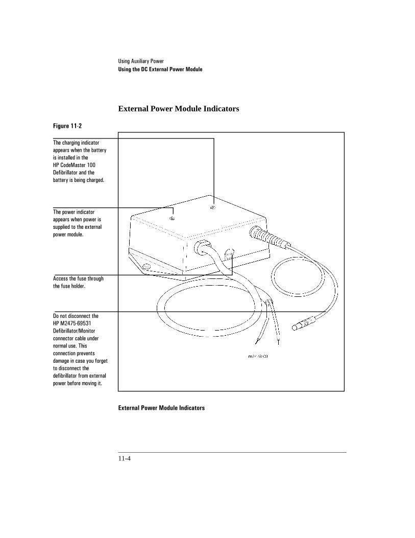
8VLQJ�$X[LOLDU\�3RZHUUsing the DC External Power Module
11-4
External Power Module Indicators
Figure 11-2
External Power Module Indicators 11-2
7KH�SRZHU�LQGLFDWRU�DSSHDUV�ZKHQ�SRZHU�LV�VXSSOLHG�WR�WKH�H[WHUQDO�SRZHU�PRGXOH��
7KH�FKDUJLQJ�LQGLFDWRU�DSSHDUV�ZKHQ�WKH�EDWWHU\�LV�LQVWDOOHG�LQ�WKH�+3 &RGH0DVWHU�����'HILEULOODWRU�DQG�WKH�EDWWHU\�LV�EHLQJ�FKDUJHG�
$FFHVV�WKH�IXVH�WKURXJK�WKH�IXVH�KROGHU�
'R�QRW�GLVFRQQHFW�WKH�+3 0�����������'HILEULOODWRU�0RQLWRU�FRQQHFWRU�FDEOH�XQGHU�QRUPDO�XVH��7KLV�FRQQHFWLRQ�SUHYHQWV�GDPDJH�LQ�FDVH�\RX�IRUJHW�WR�GLVFRQQHFW�WKH�GHILEULOODWRU�IURP�H[WHUQDO�SRZHU�EHIRUH�PRYLQJ�LW�

8VLQJ�$X[LOLDU\�3RZHUUsing the DC External Power Module
11-5
Installing the External DC Power Module
You must be a qualified mechanic or electrician to install the power module. If the cable provided for input to the External Power Module is not long enough, make sure that you use 14 gauge or larger wire to extend the cable.
Incorrect polarity connection will cause fuse to open.
Figure 11-3
Connection of External Power Module 11-3
The External Power Module can be connected to any 12 Volt negative ground source. The circuit which supplies power to the external power module should be protected by a fuse between 10 amps and 20 amps. This allows sufficient power to operate the External Power Module and still provides electrical protection in case of faulty or defective wiring to the External Power Module.
The power module attempts to draw power from the vehicle 12 Volt system whenever the defibrillator/monitor is on and whenever the defibrillator/monitor battery is charging. If you do not want power drawn from the vehicle when the vehicle is not running then install the External Power Module so that it is electrically disconnected when the vehicle is off.
CAUTION
([WHUQDO�3RZHU�0RGXOH
���9�6XSSO\�²
%ODFN 5HG
&RQQHFW�WKH�EODFN�ZLUH�WR�JURXQG�DQG�WKH�UHG�ZLUH�WR�����9ROWV�

8VLQJ�$X[LOLDU\�3RZHUUsing the DC External Power Module
11-6
Testing the External Power Module Installation
To verify that the External Power Module is correctly installed:
1 Connect the external power module to the HP CodeMaster 100 external power input. Verify that the power indicator on the external power module and the external power indicator on the HP CodeMaster 100 both appear.
2 Install a battery in the HP CodeMaster 100 and verify that the charging indicator appears on the External Power Module.
3 Remove the battery and turn the Energy Select/Monitor On control on the HP CodeMaster 100 to 360J. Press Charge and verify that the defibrillator charged to 360J in 15 seconds or less.

8VLQJ�$X[LOLDU\�3RZHUCodeMaster 100 External Power Indicators
11-7
11CodeMaster 100 External Power Indicators
This section discusses the external power indicators on the HP CodeMaster 100 (see Figure 11-4).
Figure 11-4
&RGH0DVWHU�����([WHUQDO�3RZHU�,QGLFDWRUV 11-4
3UHVV�WKH�EDWWHU\�FDSDFLW\�JDXJH�WR�VKRZ�WKH�FKDUJH�OHYHO�RI�WKH�EDWWHU\��
7KH�H[WHUQDO�SRZHU�LQGLFDWRU�OLJKW�DSSHDUV�ZKHQHYHU�WKH�3RZHU�0RGXOH�LV�VXSSO\LQJ�SRZHU�
7KH�GHILEULOODWRU�LQWHUIDFH�FDEOH�RI�WKH�3RZHU�0RGXOH�DWWDFKHV�WR�WKH�H[WHUQDO�SRZHU�LQSXW�

8VLQJ�$X[LOLDU\�3RZHUMonitoring with External Power
11-8
11Monitoring with External Power
7XUQ�WKH�(QHUJ\�6HOHFW�3RZHU�&RQWURO�WR�0RQLWRU�2Q�WR�PRQLWRU�ZKLOH�XVLQJ�WKH�3RZHU�0RGXOH��3RZHU�IRU�PRQLWRULQJ�FRPHV�IURP�WKH�3RZHU�0RGXOH�DQG�GRHV�QRW�GHSOHWH�WKH�GHILEULOODWRU�PRQLWRU�EDWWHU\�
11Charging the Battery with an Auxiliary Power Module
If the battery is not already charged and it is at operating temperature, it will charge whenever you plug the external power module into the defibrillator. The charging indicator on the external power module appears when the battery is charging. The indicator may disappear briefly after you turn the defibrillator off. When you charge the defibrillator the battery does not charge, so the indicator disappears until the defibrillator is charged.
7KH�3RZHU�0RGXOH�FKDUJHV�WKH�EDWWHU\�PRUH�TXLFNO\�LI�WKH�GHILEULOODWRU�LV�LQ�2II�PRGH��,I�\RX�WXUQ�WKH�(QHUJ\�6HOHFW�3RZHU�&RQWURO�WR�0RQLWRU�2Q�RU�WR�DQ�HQHUJ\�OHYHO��WKH�EDWWHU\�VWLOO�FKDUJHV��EXW�QRW�DV�TXLFNO\�
7KH�EDWWHU\�FKDUJHV�PRUH�VORZO\�ZKHQ�WKH�WHPSHUDWXUH�LV�EHORZ����&������)��RU�DERYH�����&�������)���7KH�EDWWHU\�GRHV�QRW�FKDUJH�DW�WHPSHUDWXUHV�DERYH�����&�������)��
5HSHDWHG�FKDUJLQJ�DW�YHU\�KLJK�RU�YHU\�ORZ�WHPSHUDWXUHV�PD\�VKRUWHQ�WKH�OLIH�RI�\RXU�EDWWHU\�
7KH�3RZHU�0RGXOH�FKDUJHV�RQO\�WKH�+3 0����%�DQG�+3 0����%�EDWWHULHV��8VH�LW�RQO\�ZLWK�WKH�+3�&RGH0DVWHU�����
NOTE

8VLQJ�$X[LOLDU\�3RZHUDefibrillating with External Power
11-9
7KH�3RZHU�0RGXOH�GRHV�QRW�UHSODFH�WKH�+3 0����%�%DWWHU\�6XSSRUW�6\VWHP��,I�\RX�UHJXODUO\�FKDUJH�EDWWHULHV�ZLWK�WKH�3RZHU�0RGXOH��SHUIRUP�D�EDWWHU\�FDSDFLW\�WHVW�RQ�HDFK�EDWWHU\�ZLWK�WKH�EDWWHU\�VXSSRUW�V\VWHP�HYHU\����GD\V��5HPHPEHU�WKDW�D�EDWWHU\�FDSDFLW\�WHVW�WDNHV�DSSUR[LPDWHO\����KRXUV�DQG�OHDYHV�WKH�EDWWHU\�IXOO\�FKDUJHG�
11Defibrillating with External Power
,I�D�EDWWHU\�LV�LQVWDOOHG�LQ�WKH�+3�&RGH0DVWHU������HQHUJ\�WR�FKDUJH�WKH�GHILEULOODWRU�FRPHV�IURP�WKH�EDWWHU\��,I�WKH�EDWWHU\�LV�GHSOHWHG��QRW�IXQFWLRQLQJ�RU�QRW�SUHVHQW��WKH�3RZHU�0RGXOH�SURYLGHV�HQHUJ\�IRU�GHILEULOODWLRQ��7KH�3RZHU�0RGXOH�LV�QRW�LQWHQGHG�WR�HOLPLQDWH�WKH�EDWWHU\��KRZHYHU��
$OWKRXJK�\RX�FDQ�RSHUDWH�WKH�GHILEULOODWRU�ZLWK�WKH�3RZHU�0RGXOH�DQG�ZLWKRXW�D�EDWWHU\�LQ�WKH�GHILEULOODWRU��\RX�VKRXOG�RQO\�GR�VR�LI�D�EDWWHU\�LV�XQDYDLODEOH�
7KH�GHILEULOODWRU�PD\�WDNH�XS�WR����VHFRQGV�WR�FKDUJH�WR�����-�ZKHQ�UXQQLQJ�XQGHU�H[WHUQDO�SRZHU�ZLWK�WKH�EDWWHU\�DEVHQW�
CAUTION
NOTE

8VLQJ�$X[LOLDU\�3RZHUPerforming Operational Checks
11-10
11Performing Operational Checks
7KH�IROORZLQJ�RSHUDWLRQDO�FKHFNV�VKRXOG�EH�SHUIRUPHG�DORQJ�ZLWK�WKH�VKLIW�FKHFNV�GHVFULEHG�LQ�WKH�+3 0����%�3RUWDEOH�'HILEULOODWRU�0RQLWRU�4XLFN�5HIHUHQFH�
���8QSOXJ�WKH�3RZHU�0RGXOH��7XUQ�RQ�WKH�+3�&RGH0DVWHU������,I�LW�GLVSOD\V�WKH�/2:�%$77(5<�PHVVDJH��UHSODFH�WKH�EDWWHU\�ZLWK�D�FKDUJHG�EDWWHU\��7XUQ�RII�WKH�GHILEULOODWRU�
���3OXJ�LQ�WKH�3RZHU�0RGXOH��0DNH�VXUH�WKDW�WKH�SRZHU�LQGLFDWRU�RQ�WKH�3RZHU�0RGXOH�DSSHDUV�DQG�WKDW�WKH� �LQGLFDWRU�RQ�WKH�&RGH0DVWHU�DSSHDUV�
���5HPRYH�WKH�EDWWHU\�IURP�WKH�+3�&RGH0DVWHU������0DNH�VXUH�WKDW�WKH�FKDUJ�LQJ�LQGLFDWRU�OLJKW�JRHV�RXW�RQ�WKH�3RZHU�0RGXOH��5H�LQVHUW�WKH�EDWWHU\�
H[W�SRZHU

12-1
12Troubleshooting
12CodeMaster 100
This chapter contains information about troubleshooting and performing diagnostics on the CodeMaster 100, the pacer, SpO2, advisory, the external power module and the 12-Lead option.
Refer to the following table for messages that relate to the CodeMaster 100 display and actions to take to correct them.
Troubleshooting the Defibrillator
Table 12-1 Failure Messages
Message Possible Solutions
DEFIB FAILURE
8VH�D�EDFN�XS�GHILEULOODWRU�DQG�FDOO�VHUYLFH��
MONITOR FAILURE
8VH�D�EDFN�XS�GHILEULOODWRU�DQG�FDOO�VHUYLFH��,I�WKHUH�LV�QR�DOWHUQDWLYH��WU\�WR�XVH�WKH�GHILEULOODWRU�ZLWKRXW�WKH�PRQLWRU��8VH�&KDUJH�'RQH�LQGLFDWRUV�WR�YHULI\�GHILEULOODWRU�IXQFWLRQDOLW\��
SYSTEM FAILURE
8VH�D�EDFN�XS�GHILEULOODWRU�DQG�FDOO�VHUYLFH��,I�WKHUH�LV�QR�DOWHUQDWLYH��WU\�WR�XVH�WKH�GHILEULOODWRU��8VH�&KDUJH�'RQH�LQGLFDWRUV�WR�YHULI\�GHILEULOODWRU�IXQFWLRQDOLW\��
Table 12-2 Defibrillator Messages
Message Cause Possible Solutions
NO PADDLES 3DGGOH�VHW�LV�QRW�FRQQHFWHG�WR�WKH�GHILEULOOD�WRU�
$WWDFK�H[WHUQDO�SDGGOHV��LQWHUQDO�SDGGOHV��RU�HOHFWURGH�DGDSWHU�DV�UHTXLUHG��
LEADS OFF /HDGV�DUH�QRW�VHFXUHO\�DWWDFKHG�WR�WKH�SDWLHQW�RU�WKH�FDEOH�LV�QRW�FRQQHFWHG�WR�WKH�GHILEULOODWRU�
$WWDFK�OHDG��

7URXEOHVKRRWLQJCodeMaster 100
12-2
USE LEADS 3DGGOHV�DUH�FRQQHFWHG�WR�WKH�GHILEULOODWRU�DQG��
� Sync�ZDV�SUHVVHG�ZKHQ�PADDLES�LV�VHOHFWHG�
� 3UHVV�Sync �WR�UHPRYH�WKH�GHILEULOODWRU�IURP�V\QF�PRGH�
� 'HILEULOODWRU�LV�LQ�V\QF�PRGH�DQG�PAD-DLES�LV�VHOHFWHG�
� 6HOHFW�LEAD I, II��RU�III�LQVWHDG�RI�PAD-DLES�
� 'HILEULOODWRU�LV�LQ�GHILE�PRGH�DQG�PADDLES�LV�VHOHFWHG�ZKHQ�OHDGV�DUH�DWWDFKHG�WR�WKH�SDWLHQW��
� 6HOHFW�LEAD I, II��RU�III�LQVWHDG�RI�PAD-DLES�
� 'HILEULOODWRU�LV�LQ�GHILE�PRGH��PAD-DLES�LV�WKH�(&*�VRXUFH�ZKHQ�DWWDFK�LQJ�OHDGV�WR�WKH�SDWLHQW��
� 6HOHFW�LEAD I, II��RU�III�LQVWHDG�RI�PAD-DLES��
50J MAXIMUM
,QWHUQDO�SDGGOHV�DUH�DWWDFKHG�DQG�WKH�Energy Select�FRQWURO�KDV�EHHQ�WXUQHG�SDVW����MRXOHV�
&RGH0DVWHU�����GHILEULOODWRU�PRQL�WRU��ZLOO�FKDUJH�WR����MRXOHV��
LOW BATTERY
%DWWHU\�YROWDJH�LV�EHORZ�WKH�ORZ�EDWWHU\�WKUHVKROG�
,QVWDOO�D�FKDUJHG�EDWWHU\�
SETUP LOST 7KH�LQWHUQDO�EDWWHU\�ZKLFK�EDFNV�XS�WKH�FRQ�ILJXUDWLRQ�PHPRU\�KDV�GHSOHWHG��
&DOO�IRU�VHUYLFH��
DEFIBDISARMED
&RGH0DVWHU�����GHILEULOODWRU�PRQLWRU�KDV�LQWHUQDOO\�GLVFKDUJHG�HQHUJ\�DQG�LV�QRZ�GLV�DUPHG��
�6ROXWLRQ�QRW�DSSOLFDEOH��
CHECK RECORDER
7KH�UHFRUGHU�GRRU�LV�RSHQ�RU�7KH�UHFRUGHU�LV�RXW�RI�SDSHU�
&ORVH�WKH�UHFRUGHU�GRRU�RU�UHSODFH�WKH�SDSHU�UROO�DV�GHVFULEHG�LQ�&KDQJLQJ�WKH�5HFRUGHU�3DSHU��SDJH��������
Table 12-2 Defibrillator Messages (Continued)
Message Cause Possible Solutions

7URXEOHVKRRWLQJCodeMaster 100
12-3
If the Defibrillator does not Charge
If the defibrillator does not charge, perform the following steps:
1 Verify the proper setting of the Energy Select control.
2 If it is correct, follow these steps.
a. Turn the Energy Select control to Off , and then back to the desired energy setting.
b. Press Charge again.
3 If the instrument remains unable to charge, turn the Energy Select con-trol to Off and use a backup defibrillator.
4 Press Review to print an event summary and keep any ECG strips from the defibrillator for later evaluation.
5 Alert HP service personnel.
CHECKBATTERY
7KH�EDWWHU\�SDFN�LV�QRW�IXOO\�LQVHUWHG�LQWR�WKH�GHILEULOODWRU�RU�LW�LV�IDXOW\�
5HLQVHUW�WKH�EDWWHU\�SDFN��PDNLQJ�VXUH�LW�ODWFKHV��,I�WKH�PHVVDJH�UHDSSHDUV��SHUIRUP�D�EDWWHU\�FDSDFLW\�WHVW�
CHECK SETUP
7KH�EDFNXS�EDWWHU\�IRU�WKH�VHWXS�FRQILJXUD�WLRQ�PHPRU\�LV�ORZ��
&DOO�VHUYLFH�WR�UHSODFH�WKH�EDFNXS�EDWWHU\��
Table 12-2 Defibrillator Messages (Continued)
Message Cause Possible Solutions

7URXEOHVKRRWLQJCodeMaster 100
12-4
If the Defibrillator does not Deliver a Shock
If the defibrillator does not deliver a shock, perform the following steps:
1 Make sure the unit is not in synchronized shock mode by checking that the Sync light is not on.
2 If the unit discharges internally (that is, the energy display decrements slowly then beeps three times and displays the screen message DEFIB DISARMED) verify proper connections from the patient to the defibrilla-tor. This includes connections to the pads/paddles adapter cable if one is being used. Also check for worn or broken areas along the cables.
3 Press Charge again, wait for the Charge Done indicators.
4 Press the Shock ( ) buttons again.
5 If the unit remains unable to shock, turn the Energy Select control to the Monitor On or Off position and use a back-up defibrillator.
6 Press Review to print an event summary and keep any ECG strips from the defibrillator for later evaluation.
7 Contact HP service personnel as soon as possible.
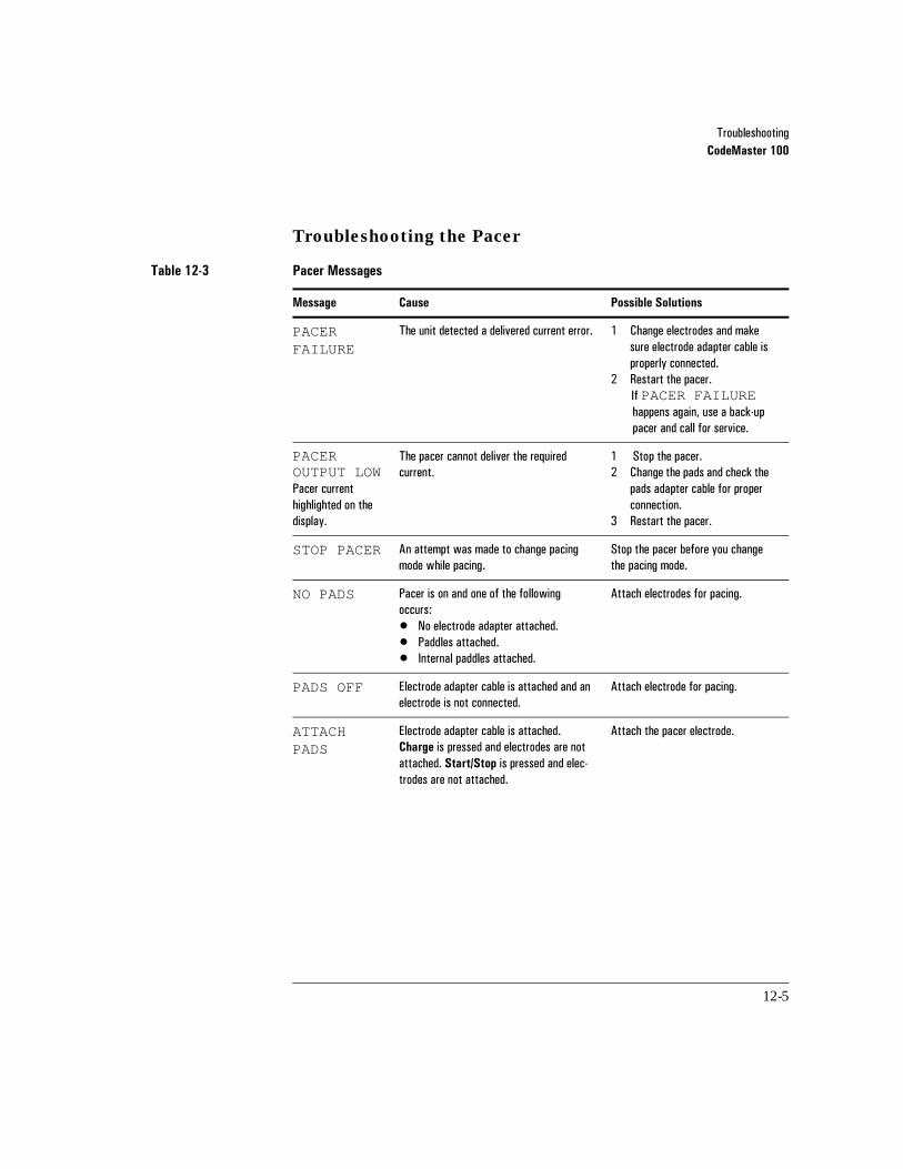
7URXEOHVKRRWLQJCodeMaster 100
12-5
Troubleshooting the Pacer
Table 12-3 Pacer Messages
Message Cause Possible Solutions
PACER FAILURE
7KH�XQLW�GHWHFWHG�D�GHOLYHUHG�FXUUHQW�HUURU� � &KDQJH�HOHFWURGHV�DQG�PDNH�VXUH�HOHFWURGH�DGDSWHU�FDEOH�LV�SURSHUO\�FRQQHFWHG�
� 5HVWDUW�WKH�SDFHU�,I�PACER FAILURE�KDSSHQV�DJDLQ��XVH�D�EDFN�XS�SDFHU�DQG�FDOO�IRU�VHUYLFH��
PACER OUTPUT LOW 3DFHU�FXUUHQW�KLJKOLJKWHG�RQ�WKH�GLVSOD\�
7KH�SDFHU�FDQQRW�GHOLYHU�WKH�UHTXLUHG�FXUUHQW�
� �6WRS�WKH�SDFHU��� &KDQJH�WKH�SDGV�DQG�FKHFN�WKH�
SDGV�DGDSWHU�FDEOH�IRU�SURSHU�FRQQHFWLRQ�
� 5HVWDUW�WKH�SDFHU�
STOP PACER $Q�DWWHPSW�ZDV�PDGH�WR�FKDQJH�SDFLQJ�PRGH�ZKLOH�SDFLQJ�
6WRS�WKH�SDFHU�EHIRUH�\RX�FKDQJH�WKH�SDFLQJ�PRGH��
NO PADS 3DFHU�LV�RQ�DQG�RQH�RI�WKH�IROORZLQJ�RFFXUV��� 1R�HOHFWURGH�DGDSWHU�DWWDFKHG�� 3DGGOHV�DWWDFKHG��� ,QWHUQDO�SDGGOHV�DWWDFKHG��
$WWDFK�HOHFWURGHV�IRU�SDFLQJ��
PADS OFF (OHFWURGH�DGDSWHU�FDEOH�LV�DWWDFKHG�DQG�DQ�HOHFWURGH�LV�QRW�FRQQHFWHG�
$WWDFK�HOHFWURGH�IRU�SDFLQJ��
ATTACH PADS
(OHFWURGH�DGDSWHU�FDEOH�LV�DWWDFKHG��Charge�LV�SUHVVHG�DQG�HOHFWURGHV�DUH�QRW�DWWDFKHG��Start/Stop�LV�SUHVVHG�DQG�HOHF�WURGHV�DUH�QRW�DWWDFKHG�
$WWDFK�WKH�SDFHU�HOHFWURGH�
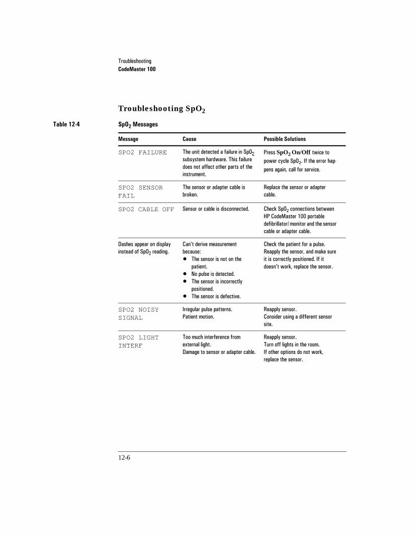
7URXEOHVKRRWLQJCodeMaster 100
12-6
Troubleshooting SpO2
Table 12-4 SpO2 Messages
Message Cause Possible Solutions
SPO2 FAILURE 7KH�XQLW�GHWHFWHG�D�IDLOXUH�LQ�6S2��VXEV\VWHP�KDUGZDUH��7KLV�IDLOXUH�GRHV�QRW�DIIHFW�RWKHU�SDUWV�RI�WKH�LQVWUXPHQW�
3UHVV�SpO2 On/Off WZLFH�WR�SRZHU�F\FOH�6S2���,I�WKH�HUURU�KDS�SHQV�DJDLQ��FDOO�IRU�VHUYLFH�
SPO2 SENSOR FAIL
7KH�VHQVRU�RU�DGDSWHU�FDEOH�LV�EURNHQ�
5HSODFH�WKH�VHQVRU�RU�DGDSWHU�FDEOH�
SPO2 CABLE OFF 6HQVRU�RU�FDEOH�LV�GLVFRQQHFWHG� &KHFN�6S2��FRQQHFWLRQV�EHWZHHQ�+3�&RGH0DVWHU�����SRUWDEOH�GHILEULOODWRU��PRQLWRU�DQG�WKH�VHQVRU�FDEOH�RU�DGDSWHU�FDEOH�
'DVKHV�DSSHDU�RQ�GLVSOD\�LQVWHDG�RI�6S2��UHDGLQJ�
&DQ·W�GHULYH�PHDVXUHPHQW�EHFDXVH�� 7KH�VHQVRU�LV�QRW�RQ�WKH�
SDWLHQW�� 1R�SXOVH�LV�GHWHFWHG�� 7KH�VHQVRU�LV�LQFRUUHFWO\�
SRVLWLRQHG�� 7KH�VHQVRU�LV�GHIHFWLYH�
&KHFN�WKH�SDWLHQW�IRU�D�SXOVH�5HDSSO\�WKH�VHQVRU��DQG�PDNH�VXUH�LW�LV�FRUUHFWO\�SRVLWLRQHG��,I�LW�GRHVQ·W�ZRUN��UHSODFH�WKH�VHQVRU�
SPO2 NOISY SIGNAL
,UUHJXODU�SXOVH�SDWWHUQV�3DWLHQW�PRWLRQ�
5HDSSO\�VHQVRU��&RQVLGHU�XVLQJ�D�GLIIHUHQW�VHQVRU�VLWH�
SPO2 LIGHT INTERF
7RR�PXFK�LQWHUIHUHQFH�IURP�H[WHUQDO�OLJKW�'DPDJH�WR�VHQVRU�RU�DGDSWHU�FDEOH�
5HDSSO\�VHQVRU�7XUQ�RII�OLJKWV�LQ�WKH�URRP�,I�RWKHU�RSWLRQV�GR�QRW�ZRUN��UHSODFH�WKH�VHQVRU�
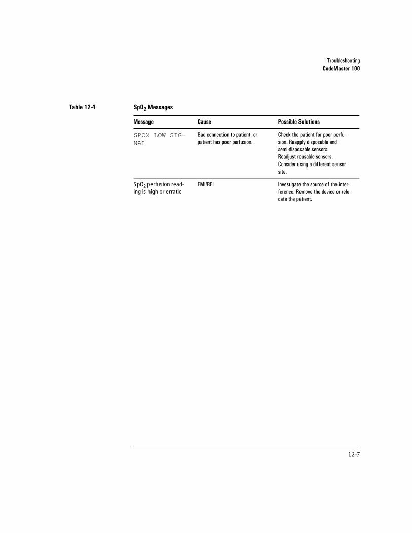
7URXEOHVKRRWLQJCodeMaster 100
12-7
SPO2 LOW SIG-NAL
%DG�FRQQHFWLRQ�WR�SDWLHQW��RU�SDWLHQW�KDV�SRRU�SHUIXVLRQ�
&KHFN�WKH�SDWLHQW�IRU�SRRU�SHUIX�VLRQ��5HDSSO\�GLVSRVDEOH�DQG�VHPL�GLVSRVDEOH�VHQVRUV�5HDGMXVW�UHXVDEOH�VHQVRUV�&RQVLGHU�XVLQJ�D�GLIIHUHQW�VHQVRU�VLWH�
SpO2 perfusion read-ing is high or erratic
(0,�5), ,QYHVWLJDWH�WKH�VRXUFH�RI�WKH�LQWHU�IHUHQFH��5HPRYH�WKH�GHYLFH�RU�UHOR�FDWH�WKH�SDWLHQW�
Table 12-4 SpO2 Messages
Message Cause Possible Solutions

7URXEOHVKRRWLQJCodeMaster 100
12-8
Troubleshooting the Advisory Mode
Table 12-5 Advisory Mode Messages
Message Cause Possible Solutions
ATTACH PADS CABLE
7KH�HOHFWURGH�DGDSWHU�FDEOH�LV�QRW�FRQQHFWHG�WR�WKH�GHILEULOODWRU�
&RQQHFW�WKH�HOHFWURGH�DGDSWHU�FDEOH�WR�WKH�GHILEULOODWRU�
FOR ANALYSIS, ATTACH PADS
'HILE�HOHFWURGHV�DUH�QRW�DWWDFKHG�WR�WKH�HOHFWURGH�DGDSWHU�FDEOH�RU�GHILE�HOHFWURGHV�DUH�QRW�DWWDFKHG�WR�WKH�SDWLHQW�
&KHFN�HOHFWURGH�FRQQHFWLRQV�
ARTIFACT DETECTED;DO NOT TOUCH PATIENT
([FHVVLYH�QRLVH�ZDV�GHWHFWHG�E\�WKH�DGYLVRU\�DOJRULWKP�GXULQJ�DQDO\VLV�
'R�QRW�WRXFK��PRYH��SHUIRUP�&35��YHQWLODWH�RU�WUDQVSRUW�WKH�SDWLHQW�ZKLOH�WKH�DGYLVRU\�DOJRULWKP�LV�DQDO\]LQJ�FDUGLDF�UK\WKPV�5HSHDW�DQDO\VLV�
PADS OFF 7KH�HOHFWURGH�DGDSWHU�FDEOH�LV�DWWDFKHG��EXW�QR�GHILE�HOHFWURGHV�DUH�FRQQHFWHG�
$WWDFK�GHILE�HOHFWURGHV�WR�HOHF�WURGH�DGDSWHU�FDEOH�DQG�WR�SDWLHQW�
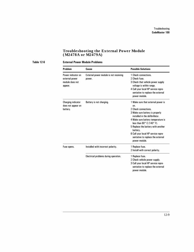
7URXEOHVKRRWLQJCodeMaster 100
12-9
Troubleshooting the External Power Module (M2478A or M2479A)
Table 12-6 External Power Module Problems
Problem Cause Possible Solutions
3RZHU�LQGLFDWRU�RQ�H[WHUQDO�SRZHU�PRGXOH�GRHV�QRW�DSSHDU�
([WHUQDO�SRZHU�PRGXOH�LV�QRW�UHFHLYLQJ�SRZHU�
� &KHFN�FRQQHFWLRQV�� &KHFN�IXVH�� &KHFN�WKDW�YHKLFOH�SRZHU�VXSSO\�YROWDJH�LV�ZLWKLQ�UDQJH�
� &DOO�\RXU�ORFDO�+3�VHUYLFH�UHSUH�VHQWDWLYH�WR�UHSODFH�WKH�H[WHUQDO�SRZHU�PRGXOH�
&KDUJLQJ�LQGLFDWRU�GRHV�QRW�DSSHDU�RQ�EDWWHU\�
%DWWHU\�LV�QRW�FKDUJLQJ� � 0DNH�VXUH�WKDW�H[WHUQDO�SRZHU�LV�RQ�
� &KHFN�FRQQHFWLRQV�� 0DNH�VXUH�EDWWHU\�LV�SURSHUO\�LQVWDOOHG�LQ�WKH�GHILEULOODWRU�
� 0DNH�VXUH�EDWWHU\�WHPSHUDWXUH�LV�OHVV�WKDQ�����&�������)��
� 5HSODFH�WKH�EDWWHU\�ZLWK�DQRWKHU�EDWWHU\�
� &DOO�\RXU�ORFDO�+3�VHUYLFH�UHSUH�VHQWDWLYH�WR�UHSODFH�WKH�H[WHUQDO�SRZHU�PRGXOH�
)XVH�RSHQV� ,QVWDOOHG�ZLWK�LQFRUUHFW�SRODULW\� � 5HSODFH�IXVH�� ,QVWDOO�ZLWK�FRUUHFW�SRODULW\�
(OHFWULFDO�SUREOHPV�GXULQJ�RSHUDWLRQ� � 5HSODFH�IXVH�� &KHFN�YHKLFOH�SRZHU�VXSSO\�� &DOO�\RXU�ORFDO�+3�VHUYLFH�UHSUH�VHQWDWLYH�WR�UHSODFH�WKH�H[WHUQDO�SRZHU�PRGXOH�
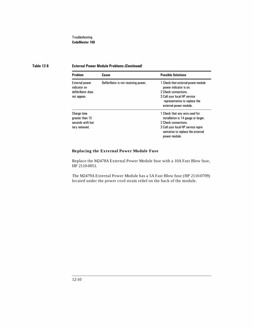
7URXEOHVKRRWLQJCodeMaster 100
12-10
Replacing the External Power Module Fuse
Replace the M2478A External Power Module fuse with a 10A Fast Blow fuse, HP 2110-0051.
The M2479A External Power Module has a 5A Fast Blow fuse (HP 2110-0709) located under the power cord strain relief on the back of the module.
([WHUQDO�SRZHULQGLFDWRU�RQ�GHILEULOODWRU�GRHV�QRW�DSSHDU�
'HILEULOODWRU�LV�QRW�UHFHLYLQJ�SRZHU� � &KHFN�WKDW�H[WHUQDO�SRZHU�PRGXOH�SRZHU�LQGLFDWRU�LV�RQ�
� &KHFN�FRQQHFWLRQV�� &DOO�\RXU�ORFDO�+3�VHUYLFH�UHSUHVHQWDWLYH�WR�UHSODFH�WKH�H[WHUQDO�SRZHU�PRGXOH�
&KDUJH�WLPH�JUHDWHU�WKDQ����VHFRQGV�ZLWK�EDW�WHU\�UHPRYHG�
� &KHFN�WKDW�DQ\�ZLUH�XVHG�IRU�LQVWDOODWLRQ�LV����JDXJH�RU�ODUJHU�
� &KHFN�FRQQHFWLRQV�� &DOO�\RXU�ORFDO�+3�VHUYLFH�UHSUH�VHQWDWLYH�WR�UHSODFH�WKH�H[WHUQDO�SRZHU�PRGXOH�
Table 12-6 External Power Module Problems (Continued)
Problem Cause Possible Solutions

7URXEOHVKRRWLQJCodeMaster 100
12-11
Performing Diagnostics
The following procedure allows functional inspection of the CodeMaster 100 portable defibrillator/monitor.
1 Turn the Energy Select control to the Monitor On position. The moni-tor trace will appear within ten seconds.
2 Press Lead Select until Lead I is displayed and verify that the message LEADS OFF appears, indicating that one or more leadwires are not connected.
3 Press Lead Select to return to the paddles ECG selection.
4 With the paper installed, press Record once to turn on the recorder.
a. Allow the recorder to run for approximately 20 seconds and check that Date, Time, HR (heart rate), SpO2, PADDLES (ECG source), and AUTOGAIN (ECG gain mode) are noted on the ECG strip.
b. Press Mark and verify that the mark ( ) symbol is printed. It will be delayed 6 seconds if the recorder is in the delayed mode.
c. Press Record to stop the recorder.
5 Press HR Alarm. Verify that the configured alarm limits appear briefly, then are replaced by the bell symbol in the upper right of the display. With no ECG signal, an audible alarm tone should sound within four seconds.
6 Press HR Alarm to turn off the alarms.
7 Verify that the adult paddle electrodes are installed.
8 Turn the Energy Select control to 100 joules.
9 Leaving the paddles in their holders, press the Charge on front panel or on the right (Apex) paddle.
•The Charge Done indicators should occur within two seconds when oper-ated with a fully charged battery.
•The Delivered Energy display should indicate 100 joules.

7URXEOHVKRRWLQJCodeMaster 100
12-12
Keep hands clear of the paddle electrode edges. Use your thumbs to depress the Shock buttons on the paddle handles.
10 Grasp the paddle handles, and without removing the paddles from their holders, press both Shock buttons simultaneously. A brief automatic recorder run prints the delivered energy test report.
11 Press Sync to place the instrument in Sync mode.
12 Verify that the messages SYNC and USE LEADS appear on the display.
13 Press Lead Select once to select Lead I, and verify that the message USE LEADS no longer appears. The message LEADS OFF should now appear, indicating that one or more leads are not connected.
14 Turn the Energy Select control to Off.
The defibrillator is ready for use if it passes the above checklist.
A more extensive test of defibrillator/monitor functionality can be performed using the diagnostic service mode described in the HP M2475B CodeMaster
100 Portable Defibrillator/Monitor Service Manual.
WARNING

7URXEOHVKRRWLQJThe 12-Lead Option
12-13
12The 12-Lead Option
If you have problems with an ECG, there are several things you may check before calling for service. This chapter tells how to solve basic ECG problems.
Checking ECG Technique
Many problems in taking an ECG may be related to electrode application.
• Review “Preparing the Patient” on page 6-10 to ensure the patient leads are prop-erly attached to the patient.
• Refer to “Checking Signal Quality” on page 6-12 for information about ensuring a good recording by using the preview screen.

7URXEOHVKRRWLQJThe 12-Lead Option
12-14
Identifying ECG Problems
The following table shows symptoms and solutions to problems that can occur when recording an ECG.
Table 12-7 ECG Problems and Solutions
Problem Cause Possible Solutions
3RZHU�OLQH�$&�,QWHUIHUHQFH 3RRU�HOHFWURGH�FRQWDFW��'U\�RU�GLUW\�HOHFWURGHV�
/HDG�ZLUHV�PD\�EH�SLFNLQJ�XS�LQWHUIHUHQFH�IURP�SRRUO\�JURXQGHG�HTXLSPHQW�QHDU�WKH�SDWLHQW�
3DWLHQW�FDEOH�LV�WRR�FORVH�WR�WKH�SRZHU�FRUGV�
$EUDGH�VNLQ��8VH�QHZ�HOHFWURGHV��5HDSSO\�HOHFWURGHV��&KHFN�H[SLUDWLRQ�GDWH�RQ�GLVSRVDEOH�HOHFWURGHV�
5RXWH�OHDG�ZLUHV�DORQJ�OLPEV�DQG�DZD\�IURP�RWKHU�HOHFWULFDO�HTXLSPHQW��)L[�RU�PRYH�SRRUO\�JURXQGHG�HTXLSPHQW�
0RYH�RWKHU�HOHFWULFDO�HTXLSPHQW�DZD\�IURP�SDWLHQW��8QSOXJ�HOHFWULF�EHG�
:DQGHULQJ�%DVHOLQH 3DWLHQW�PRYHPHQW�
(OHFWURGH�PRYHPHQW��3RRU�HOHFWURGH�FRQWDFW�DQG�VNLQ�SUHSDUDWLRQ�
5HVSLUDWRU\�LQWHUIHUHQFH�
5HDVVXUH�DQG�UHOD[�WKH�SDWLHQW�
%H�VXUH�WKDW�WKH�OHDG�ZLUHV�DUH�QRW�SXOOLQJ�RQ�WKH�HOHF�WURGHV��5HDSSO\�HOHFWURGHV��3UHVV�WKH�Filter�NH\�LI�LW�LV�FRQILJXUHG�IRU�%DVHOLQH�:DQGHU�
0RYH�OHDG�ZLUHV�DZD\�IURP�DUHDV�ZLWK�WKH�JUHDWHVW�UHVSLUDWRU\�PRWLRQ�
7UHPRU�RU�0XVFOH�$UWLIDFW 3RRU�HOHFWURGH�SODFHPHQW��3RRU�HOHFWURGH�FRQ�WDFW��3DWLHQW�LV�FROG�
7HQVH��XQFRPIRUWDEOH�SDWLHQW�
7UHPRUV�
&OHDQ�WKH�HOHFWURGH�VLWHV��5HDSSO\�HOHFWURGHV��%H�VXUH�WKH�OLPE�HOHFWURGHV�DUH�SODFHG�RQ�IODW��QRQ�PXVFXODU�DUHDV��:DUP�WKH�SDWLHQW�
5HDVVXUH�DQG�UHOD[�WKH�SDWLHQW��3UHVV�WKH�Filter�NH\�LI�LW�LV�FRQILJXUHG�IRU�$UWLIDFW�
$WWDFK�WKH�OLPE�HOHFWURGHV�QHDU�WKH�WUXQN��3UHVV�WKH�Filter�NH\�LI�LW�LV�FRQILJXUHG�IRU�$UWLIDFW�

7URXEOHVKRRWLQJThe 12-Lead Option
12-15
Identifying Recorder Problems
The following table shows symptoms and solutions to problems that can occur when the recorder will not start.
If you continue to have problems with the 12-Lead option, call your local Hewlett-Packard service representative (see “Service” on page 12-21).
,QWHUPLWWHQW�RU�-LWWHU\�:DYHIRUP
3RRU�HOHFWURGH�FRQWDFW��'U\�HOHFWURGHV�
)DXOW\�OHDG�ZLUHV�
&OHDQ�WKH�HOHFWURGH�VLWH��5HDSSO\�HOHFWURGHV��&KHFN�H[SLUDWLRQ�GDWH�RQ�GLVSRVDEOH�HOHFWURGHV�
5HSODFH�IDXOW\�SDWLHQW�FDEOH�
�$IWHU�SRZHULQJ�RQ�WKH�XQLW�RU�GXULQJ�QRUPDO�RSHUDWLRQ��WKH�PHVVDJH��$WWDFK�WKH�+3����/HDG�(&*�FDEOH�WR�WDNH�D����/HDG��GLVSOD\V�
7KH�FDEOH�LVQ·W�SURSHUO\�FRQQHFWHG� $WWDFK�WKH����/HDG�FDEOH�WR�WKH�GHYLFH�
Table 12-7 ECG Problems and Solutions (Continued)
Problem Cause Possible Solutions
Table 12-8 Recorder Problems and Solutions
Problem Cause Possible Solutions
$IWHU�DFTXLULQJ�DQ�(&*��WKH�DVVRFLDWHG�UHSRUW�GRHV�QRW�SULQW
7KH�UHFRUGHU�RU�SDSHU�LV�RXW�DQG�WKH�PHVVDJH��&KHFN�UHFRUGHU��GLVSOD\V
/RDG�WKH�SDSHU�DQG�FKHFN�UHFRUGHU�GRRU��
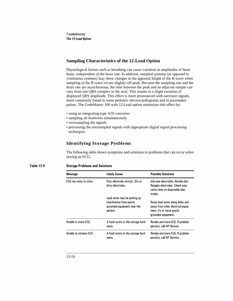
7URXEOHVKRRWLQJThe 12-Lead Option
12-16
Sampling Characteristics of the 12-Lead Option
Physiological factors such as breathing can cause variation in amplitudes of heart beats, independent of the heart rate. In addition, sampled systems (as opposed to continuous systems) may show changes in the apparent height of the R-wave when sampling of the R-wave occurs slightly off-peak. Because the sampling rate and the heart rate are asynchronous, the time between the peak and an adjacent sample can vary from one QRS complex to the next. This results in a slight variation of displayed QRS amplitude. This effect is more pronounced with narrower signals, more commonly found in some pediatric electrocardiograms and in pacemaker pulses. The CodeMaster 100 with 12-Lead option minimizes this effect by:
• using an integrating-type A/D converter• sampling all leadwires simultaneously• oversampling the signals• processing the oversampled signals with appropriate digital signal processing
techniques
Identifying Storage Problems
The following table shows symptoms and solutions to problems that can occur when storing an ECG.
Table 12-9 Storage Problems and Solutions
Message Likely Cause Possible Solutions
(&*�WRR�QRLV\�WR�VWRUH 3RRU�HOHFWURGH�FRQWDFW��'U\�RU�GLUW\�HOHFWURGHV�
/HDG�ZLUHV�PD\�EH�SLFNLQJ�XS�LQWHUIHUHQFH�IURP�SRRUO\�JURXQGHG�HTXLSPHQW�QHDU�WKH�SDWLHQW�
8VH�QHZ�HOHFWURGHV��$EUDGH�VNLQ��5HDSSO\�HOHFWURGHV��&KHFN�H[SL�UDWLRQ�GDWH�RQ�GLVSRVDEOH�HOHF�WURGHV�
5RXWH�OHDG�ZLUHV�DORQJ�OLPEV�DQG�DZD\�IURP�RWKHU�HOHFWULFDO�HTXLS�PHQW��)L[�RU�PRYH�SRRUO\�JURXQGHG�HTXLSPHQW�
8QDEOH�WR�VWRUH�(&* $�IDXOW�H[LVWV�LQ�WKH�VWRUDJH�KDUG�ZDUH�
5HWDNH�DQG�VWRUH�(&*��,I�SUREOHP�SHUVLVWV��FDOO�+3�6HUYLFH�
8QDEOH�WR�UHWULHYH�(&* $�IDXOW�H[LVWV�LQ�WKH�VWRUDJH�KDUG�ZDUH�
5HWDNH�DQG�VWRUH�(&*��,I�SUREOHP�SHUVLVWV��FDOO�+3�6HUYLFH�

7URXEOHVKRRWLQJThe 12-Lead Option
12-17
Identifying Transmission Problems
The following table shows symptoms and solutions to problems that can occur when transmitting an ECG.
Table 12-10 Transmission Problems and Solutions
Message Likely Cause Possible Solutions
7HOHSKRQH�EXV\��UH�GLDOLQJ %XV\�WHOHSKRQH�QXPEHU� ���/HDG�ZLOO�DXWRPDWLFDOO\�UH�GLDO��ZDLWLQJ����VHFRQGV�EHWZHHQ�DWWHPSWV�
1R�DQVZHU��UH�GLDOLQJ 5HPRWH�PRGHP�QRW�FRQQHFWHG�
0RGHP�LV�VHW�WR�JLYH�XS�DIWHU�WRR�IHZ�ULQJV�
5HSRUW�SUREOHP�WR�UHPRWH�VLWH�
&KHFN�FRQILJXUDWLRQ�RI�PRGHP�UHJLVWHU�6���6HH�\RXU�PRGHP�GRFXPHQWDWLRQ�IRU�PRUH�LQIRUPD�WLRQ�
&KHFN�WHOHSKRQH�FDEOH 1R�GLDO�WRQH� &KHFN�WKH�FRQQHFWLRQ�WR�WKH�WHOH�SKRQH�V\VWHP�%H�VXUH�WKH�WHOHSKRQH�V\VWHP�LV�LQ�RSHUDWLRQ�5HSODFH�WKH�WHOHSKRQH�FDEOH�&KHFN�ZLWK�\RXU�ORFDO�WHOHSKRQH�DGPLQLVWUDWRU��&KHFN�WKDW�WKH�SKRQH�KDV�ULQJHU�HTXLYDOHQFH�QXPEHU��5(1��RQ�ERW�WRP�RU�EDFN�RI�SKRQH�XQLW�WR�GHWHUPLQH�LI�WHOHSKRQH�V\VWHP�LV�3XEOLF�6ZLWFKHG�7HOHSKRQH�1HWZRUN��3671��
&KHFN�PRGHP�DQG�FDEOH 1R�SRZHU�WR�PRGHP��RU�SRRU�PRGHP�FDEOH�FRQQHFWLRQ�
&KHFN�WKDW�WKH�PRGHP�LV�WXUQHG�RQ��&KHFN�WKH�GDWD�FRPPXQLFD�WLRQ�FDEOH�FRQQHFWLRQV�EHWZHHQ�WKH�PRGHP�DQG�WKH����/HDG�
&KHFN�FDEOH 3RRU�FDEOH�FRQQHFWLRQ� &KHFN�DOO�FDEOH�FRQQHFWLRQV�5HSODFH�FDEOH�
1R�PRGHP�DW�UHPRWH�VLWH 5HPRWH�VLWH�DQVZHUHG��EXW�QR�PRGHP�FDUULHU�ZDV�GHWHFWHG��RU�D�ID[�PDFKLQH�DQVZHUHG�
9HULI\�WUDQVPLVVLRQ�W\SH�ZLWK�UHPRWH�VLWH��&KHFN�WHOHSKRQH�QXPEHU��5H�WU\�WUDQVPLVVLRQ�

7URXEOHVKRRWLQJThe 12-Lead Option
12-18
1R�ID[�DW�UHPRWH�VLWH 5HPRWH�VLWH�DQVZHUHG��EXW�QR�ID[�PDFKLQH�ZDV�GHWHFWHG��RU�D�PRGHP�DQVZHUHG�
9HULI\�WUDQVPLVVLRQ�W\SH�ZLWK�UHPRWH�VLWH��&KHFN�WHOHSKRQH�QXPEHU��5H�WU\�WUDQVPLVVLRQ�
&KHFN�PRGHP�FRQILJXUDWLRQ ,QFRPSDWLEOH�RU�LPSURSHUO\�LQLWLDO�L]HG�PRGHP�
9HULI\�WKH�PRGHP�LQLWLDOL]DWLRQ�VWULQJ�5HIHU�WR�PRGHP�VSHFLILFDWLRQV�LQ�&KDSWHU�����´6SHFLILFDWLRQVµ��9HULI\�WKDW�\RXU�PRGHP�LV�FRP�SDWLEOH�
,QFRPSDWLEOH�ID[�PDFKLQH�DW�UHPRWH�VLWH�
7KH�ID[�PDFKLQH�DW�WKH�UHPRWH�VLWH�LV�QRW�D�JURXS�,,,�GHYLFH�
7UDQVPLVVLRQ�UHTXLUHV�D�JURXS�,,,�ID[�PDFKLQH�DW�UHPRWH�VLWHV�
7UDQVPLVVLRQ�VWRSSHG�XQH[�SHFWHGO\��;�RI�1�(&*V�VHQW�&DEOH�PRGHP�SUREOHP��3UHVV�DQ\�NH\�WR�FRQWLQXH�
1R�SRZHU�WR�PRGHP��RU�SRRU�PRGHP�FDEOH�FRQQHFWLRQ�
&KHFN�WKDW�WKHUH�LV�SRZHU�WR�WKH�PRGHP��&KHFN�WKH�GDWD�FRPPX�QLFDWLRQ�FDEOH�FRQQHFWLRQV��&DOO�WKH�RWKHU�ORFDWLRQ�WR�YHULI\�WKHLU�PRGHP�LV�IXQFWLRQLQJ�FRUUHFWO\�
7UDQVPLVVLRQ�VWRSSHG�XQH[�SHFWHGO\��;�RI�1�(&*V�VHQW�0RGHP�ZDV�GLVFRQQHFWHG��3UHVV�DQ\�NH\�WR�FRQWLQXH�
3UREOHP�ZLWK�WHOHSKRQH�OLQH� &KHFN�WKDW�WKH�PRGHP�LV�FRQ�QHFWHG�WR�WKH�WHOHSKRQH�OLQH��9HU�LI\�WKDW�WKH�WHOHSKRQH�OLQH�LV�ZRUNLQJ�
7UDQVPLVVLRQ�VWRSSHG�XQH[�SHFWHGO\��;�RI�1�(&*V�VHQW��5HPRWH�VLWH�VWRSSHG�FRPPXQL�FDWLRQ��QQ���3UHVV�DQ\�NH\�WR�FRQWLQXH�
&RPPXQLFDWLRQ�VSHHG�RI�WKH�UHPRWH�GHYLFH�GRHV�QRW�PDWFK�WKDW�RI�WKH����/HDG��RU�UHPRWH�VLWH�PRGHP�PDOIXQFWLRQ�
&DOO�WKH�UHPRWH�ORFDWLRQ�WR�YHULI\�WKDW�WKH�FRPPXQLFDWLRQ�VSHHG�LV�FRUUHFW�DQG�WKDW�WKH�PRGHP�LV�IXQFWLRQLQJ�FRUUHFWO\��5HGXFH�WKH�FRPPXQLFDWLRQ�VSHHG�RI�ERWK�WKH����/HDG�DQG�UHPRWH�VLWH�PRGHPV�
&DQQRW�VHQG�WR�D�7UDFH0DVWHU�$�%��3DJH:ULWHU����������RU�3DJH:ULWHU�;/L��XVLQJ�D�FHOOXODU��OLQH�ZLWKRXW�WKH�XVH�RI�D�*DWH�ZD\
6HQGLQJ�(&*V�WR�WKHVH�UHFHLYHU�W\SHV�RYHU�D�FHOOXODU�OLQH�UHTXLUHV�WKH�XVH�RI�D�*DWHZD\�
&RQILJXUH�WKH�*DWHZD\�SKRQH�QXPEHU�ZLWK�WKH�QXPEHU�RI�\RXU�*DWHZD\�
&KDQJH�WKH�OLQH�W\SH�RQ�WKH�KRPH�VFUHHQ�WR�7RQH�RU�3XOVH�DQG�XVH�D�ODQG�ODQGOLQH�
Table 12-10 Transmission Problems and Solutions (Continued)
Message Likely Cause Possible Solutions

7URXEOHVKRRWLQJSales
12-19
12Sales
For the HP sales office nearest to you, please refer to your local phone book or call your HP regional office:
7KH�(&*�0DQDJHU�JDWHZD\�FDQ�RQO\�UHFHLYH�RQH�(&*��7KH�ILUVW�(&*�KDV�EHHQ�VXFFHVVIXOO\�VHQW�
7KH�*DWHZD\�LV�OLPLWHG�WR�UHFHLYLQJ�RQH�DXWR�IRUZDUGHG�(&*�
6HOHFW�RQH�(&*�DW�D�WLPH�IRU�WUDQVPLVVLRQ�IURP�WKH�6HQG�(&*V�VFUHHQ�
Table 12-10 Transmission Problems and Solutions (Continued)
Message Likely Cause Possible Solutions

7URXEOHVKRRWLQJSales
12-20
United States of America:
+HZOHWW�3DFNDUG�&RPSDQ\
0HGLFDO�3URGXFWV�*URXS�+HDGTXDUWHUV
�����0LQXWHPDQ�5RDG
$QGRYHU��0DVVDFKXVHWWV�������
0HGLFDO�&XVWRPHU�,QIRUPDWLRQ��������������
Canada:
+HZOHWW�3DFNDUG��&DQDGD��/WG�
�����6SHFWUXP�:D\
0LVVLVVDXJD��2QWDULR�/�:��*�
��������������
Marketing Center Europe:
+HZOHWW�3DFNDUG�*PE+
0HGLFDO�3URGXFWV�*URXS
+HUHQEHUJHU�6WUDEH����
������%RHEOLQJHQ
*HUPDQ\
������������������
Latin America:
+HZOHWW�3DFNDUG�/DWLQ�$PHULFD
�����%OXH�/DJRRQ�'ULYH
�WK�)ORRU
0LDPL��)ORULGD������
��������������
Medical Distribution Europe/Middle East/Africa:
���UXH�9H\URW
�����0H\ULQ��
*HQHYD��6ZLW]HUODQG
�����������������
�����������������
Asia Pacific Headquarters:
+HZOHWW�3DFNDUG�$VLD�3DFLILF�/WG�
������)�6KHOO�7RZHU��7LPHV�6TXDUH
��0DWKHVRQ�6WUHHW��&DXVHZD\�%D\
+RQJ�.RQJ
����������������
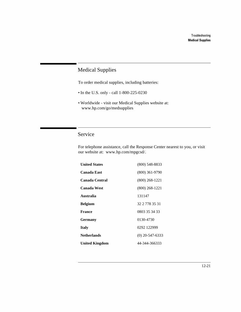
7URXEOHVKRRWLQJMedical Supplies
12-21
12Medical Supplies
To order medical supplies, including batteries:
• In the U.S. only - call 1-800-225-0230
• Worldwide - visit our Medical Supplies website at: www.hp.com/go/medsupplies
12Service
For telephone assistance, call the Response Center nearest to you, or visit our website at: www.hp.com/mpgcsd/.
United States (800) 548-8833
Canada East (800) 361-9790
Canada Central (800) 268-1221
Canada West (800) 268-1221
Australia 131147
Belgium 32 2 778 35 31
France 0803 35 34 33
Germany 0130-4730
Italy 0292 122999
Netherlands (0) 20-547-6333
United Kingdom 44-344-366333

7URXEOHVKRRWLQJService
12-22

13-1
13Maintenance
13CodeMaster 100
Operation Checks
These checks are intended to briefly verify the proper operation of the HP CodeMaster 100. Regularly perform a test routine incorporating the following checks along with visual inspection of all cables, paddles, and controls.
Every Shift
Perform the following checks every shift:
o Make sure that a battery is charging in the battery support system.
o Turn on the HP CodeMaster 100. If the system displays the LOW BATTERY message, replace the battery with a charged battery.
o Check for adequate thermal paper in the recorder.
o Check for ECG leads, electrodes, and adequate electrolyte medium.
If you have an external power module, perform these additional checks every shift:
o Unplug the AC or DC external power module. Turn on the HP CodeMaster 100. If it displays the LOW BATTERY message, replace the battery with a charged battery. Turn off the defibrillator.
o Plug in the external power module. Make sure that the power indicator on the external power module appears and that the external power indicator on the HP CodeMaster 100 appears.
o Remove the battery from the HP CodeMaster 100. Make sure that the charging indicator on the external power module disappears. Replace the battery.

0DLQWHQDQFHCodeMaster 100
13-2
Every Day
o Inspect the battery in the HP CodeMaster 100 for visible signs of wear.
o Turn on the HP CodeMaster 100. If the instrument displays the LOW BATTERY message, replace the battery with a charged battery.
o Visually check the patient cables, paddles, cables, and pads adapter cables for wear, insulation nicks, and other damage.
o Perform the “Delivered Energy and Shock Button Functional Test” on page 13-3.
o Perform the “Electrode Adapter Cable Test” on page 13-4.
o Perform the “Quick Pacer Functionality Test” on page 13-5.
o Make sure that a battery is charging in the battery support system.
If you have the advisory option:
o Turn the Energy Select control to Advisory On, and check that the instrument turns on.

0DLQWHQDQFHCodeMaster 100
13-3
Delivered Energy and Shock Button Functional Test
To check the HP CodeMaster 100 with the paddles, perform the following steps:
The HP CodeMaster 100 is designed to protect against delivering a shock when only one switch on the paddle set is pushed.
1 Turn the Energy Select control to the 100 joules position.
2 Verify that the adult paddle electrodes are installed.
3 Push the paddles completely into their holders (Apex paddle in right pocket, Sternum in left) and press either Charge. Wait for the Charge Done indicators.
Keep hands clear of the paddle electrode edges. Use your thumbs to depress the Shock ( ) buttons on the paddle handles.
4 With the paddles in their holders, grasp the paddle handles and press the Apex paddle Shock ( ) button. Verify that the defibrillator does not discharge.
5 Release the Apex paddle Shock button, then press the Sternum paddle Shock button. Verify that the defibrillator does not discharge.
6 Press Sync to place the defibrillator in sync mode.
7 Press and hold both Shock buttons. Verify that the defibrillator does not discharge.
8 Press Sync again to remove the defibrillator from sync mode.
9 With the paddles in their holders, press and briefly hold both Shock but-tons at once. Verify that the defibrillator discharges.
10 The recorder will print a test report. Review the test report for proper operation.
NOTE
WARNING
0DLQWHQDQFHCodeMaster 100
13-4
Notify Service Personnel if the ECG strip does not print TEST 100J PASSED or if any of the shock button tests fail.
If you see the CHECK SETUP message on the screen, call service to replace the backup battery.
Electrode Adapter Cable Test
To check the electrode adapter cable, perform the following steps:
1 Connect the HP M1781A test load to the electrode adapter cable.
2 Turn Energy Select to 100 joules.
3 Press Charge. Wait for the Charge Done indicators.
4 Press the left Shock ( ) button on the pads adapter cable connector housing. Verify that the defibrillator does not discharge.
5 Release the left Shock button and press the right Shock button on the pads adapter cable connector housing. Verify that the defibrillator does not discharge.
6 Press Sync to place the defibrillator in sync mode.
7 Press and hold both Shock buttons. Verify that the defibrillator does not discharge.
8 Press Sync again to remove the defibrillator from sync mode.
9 While holding down Charge, press both Shock buttons on the pads adapter cable connector. Verify the defibrillator discharges.
The recorder will print a test report.
NOTE
CAUTION
0DLQWHQDQFHCodeMaster 100
13-5
Notify Service Personnel if the ECG strip does not print TEST 100J PASSED or if any of the shock button tests fail.
If you see the CHECK SETUP message on the screen, call service to replace the backup battery.
10 Disconnect the test load (M1781A) from the electrode adapter cable.
Quick Pacer Functionality Test
1 Connect the electrode adapter cable to the defibrillator and the HP M1781A test load to the adapter cable. Turn the defibrillator on by turning the Energy Select switch to the Monitor On position.
2 Press Pacer On. (During the test only, ignore the LEADS OFF warning message if it occurs.)
3 Put the pacer into the Fixed Mode of operation by pressing Mode.
4 Adjust the current to 30 mA by pressing Output. Adjust the pacer rate to 60 pulses per minute by pressing Rate.
5 Start the pacer by pressing Start/Stop on the pacer keypad, and start the recorder by pressing Record on the recorder keypad.
6 Verify that pacer pulses are shown on the recorder strip approximately every 5 large boxes.
If the recorder is in delay mode it will take several seconds before pulses appear.
Allow the pacer to run for 10-12 seconds.
7 Turn the pacer off by pressing Pacer On and stop the recorder printing by pressing Record. Disconnect the test load from the pads adapter cable.
NOTE
CAUTION
NOTE
0DLQWHQDQFHCodeMaster 100
13-6
Notify service personnel if the message PACER FAILURE is displayed on the monitor, the unit beeps three times and displays the message PACER OUTPUT LOW or the pacer pulses are not shown on the recorder strip as described above.
Every Week
Perform the following checks on the internal paddle set every week:
o Check for excessive residue from electrolyte medium on the paddle set and clean as needed. See “Cleaning the Electrodes and Cables” on page 13-10. Oxidation can be an indication the paddle set is old and must be replaced.
o Check for pitting or discoloration on the electrode surfaces. Replace as required.
o Ensure that the cable, connector, and electrodes have no cracks in the insulation.
Every Three Months
Perform the following checks every three months.
o Have the cable set tested for electrical continuity every three months.
o Perform a battery capacity test using the HP M2480B battery support system.
See the HP M2475B CodeMaster 100 Portable Defibrillator/Monitor Service
Manual for extensive electrical, operational and safety tests to be performed by a qualified Biomedical Equipment Technician (BMET) or equivalent service technician every three to six months.
NOTE

0DLQWHQDQFHCodeMaster 100
13-7
Maintaining the Defibrillator
This section contains information about maintaining and cleaning the HP CodeMaster 100.
Changing the Recorder Paper
To change the recorder paper, perform the following steps:
1 Slide the recorder door to the right of the defibrillator as shown Figure 13-1. The paper platen will tilt up.
2 Pull up on the plastic removal tag to remove the empty or low paper roll.
Figure 13-1
Changing the Recorder Paper 13-1
3 Place a new roll of recorder paper (HP 40457C/D) in the recorder so that the paper unrolls from the top of the roll and the grid faces down as it comes out of the recorder.
4 Pull the end of the paper past the recorder platen.
5 While holding the recorder door open (to the right), press the platen down over the paper.
6 Allow the door to close over the platen roller.

0DLQWHQDQFHCodeMaster 100
13-8
7 Turn on the defibrillator and press Record to verify the paper is loaded properly.
Cleaning the Recorder Printhead
If the ECG strip has light or varying density printing, clean the printhead to remove any possible buildup of paper residue.
To clean the printhead, perform the following steps:
1 Slide the recorder door to the right of the defibrillator. The paper platen will tilt up.
2 Remove the paper roll.
3 Clean the printhead surface (above the brush) with rubbing alcohol and a cotton swab.
4 Re-install the paper roll.
5 While holding the recorder door open (to the right), press the platen down over the paper.
6 Allow the door to close over the platen roller.
7 Press Record to test the printer functionality.
0DLQWHQDQFHCodeMaster 100
13-9
Cleaning Exterior Surfaces
The HP CodeMaster 100 and accessories (except the ECG cable and carry bag) are chemically resistant to common hospital cleaning solutions and non-caustic detergents. The following list includes some approved cleaning solutions:
•90% Isopropyl alcohol (except adapters and patient cable)
•Soap and water
•Chlorine bleach (30 ml/l water)
The following list includes practices for keeping the HP CodeMaster 100 exterior surfaces clean:
•Keep the outside of the instrument clean and free of dust and dirt. Clean the paddles thoroughly to prevent build-up of dried electrolyte medium.
•Do not allow any fluids to penetrate the instrument case. Avoid pouring fluid on the unit while cleaning.
•Do not use abrasive cleaners, or strong solvents such as acetone or ace-tone-based compounds.
•Clean the display screen carefully. It is especially sensitive to rough handling and subject to scratching.
•Do not steam sterilize the monitoring leads, submerge them for prolonged periods, or heat them above 50°C. If metallic surfaces become oxidized, clean them with a very light abrasive (toothpaste). Do not use highly abrasive cleaners such as steel wool or silver polish.
•Do not steam or gas sterilize the external paddle set.

0DLQWHQDQFHCodeMaster 100
13-10
Cleaning the Electrodes and Cables
Defibrillator pads are single use and do not require cleaning. Monitoring electrodes are single use and do not require cleaning. Clean the defibrillator paddles and handles, the SpO2 sensors and leads, and the ECG leads with a soft cloth moistened with a recommended disinfectant or cleaning agent from the following list:
• Cidex®• Alcohol-free hand soap• 10% solution of Clorox® in water (may discolor cable)
Wring any excess moisture from the cloth before cleaning.
Remove all electrolyte medium from paddle surfaces and handles.
Do not clean the patient cable with alcohol. Alcohol can cause the plastic to become brittle and may cause the cable to fail prematurely.
Do not autoclave the cable or use ultrasonic cleaners.
Do not immerse the patient cable.
Do not use abrasive materials to clean metal surfaces—scratches on them can cause artifacts on the ECG.
Do not wet the connectors, especially the 12-pin connector.
Inspect disposable electrode packaging and disposable defibrillator pads packaging for seal integrity and expiration date before use.
Cleaning the Carry Bag (M3710A)
Remove all contents from the side pouches, including the shorting bar (HP part number M3710-80030) which is stored in a small pocket inside the left pouch. Machine wash the carry bag in cold water with a mild detergent. Do not use bleach or wring. Line dry only.
CAUTION

0DLQWHQDQFHCodeMaster 100
13-11
Cleaning Exterior Surfaces on the AC and DC Power Modules
7KH�3RZHU�0RGXOH�VKRXOG�EH�NHSW�FOHDQ�DQG�IUHH�RI�GXVW��7KH�PRGXOH�LV�FKHPLFDOO\�UHVLVWDQW�WR�FRPPRQ�KRVSLWDO�FOHDQLQJ�VROXWLRQV�DQG�QRQ�FDXVWLF�GHWHUJHQWV��7KH�IROORZLQJ�OLVW�LQFOXGHV�VRPH�DSSURYHG�FOHDQLQJ�VROXWLRQV�
�������,VRSURS\O�DOFRKRO�
���6RDS�DQG�ZDWHU
���&KORULQH�EOHDFK�����PO�O�ZDWHU�
:KHQ�FOHDQLQJ�WKH�3RZHU�0RGXOH�
���'R�QRW�DOORZ�IOXLGV�WR�SHQHWUDWH�WKH�LQVWUXPHQW�FDVH��DYRLG�SRXULQJ�IOXLG�RQ�WKH�XQLW�
���'R�QRW�XVH�DEUDVLYH�FOHDQHUV�RU�VWURQJ�VROYHQWV�VXFK�DV�DFHWRQH�RU�DFH�WRQH�EDVHG�FRPSRXQGV�
Maintaining the Battery
Use only the HP M2480B battery support system to charge HP M2476B/M2477B battery packs. You should also use only the HP M2480B battery support system to discharge, recondition and perform a capacity test on these batteries. It is recommended that you charge batteries at room temperature (10-30°C).
Be sure to alternate batteries between the HP CodeMaster 100 and the battery support system. Install a freshly charged battery pack in the HP CodeMaster 100 whenever the unit displays the warning message LOW BATTERY. Return the depleted battery pack to the battery support system to be charged.
Perform the capacity test on each battery every 90 days or when the battery support system indicates a capacity test should be performed. If capacity test fails, remove the battery pack from service.
Use batteries regularly. If stored longer than 30 days, perform a capacity test on the battery before using it.
0DLQWHQDQFHCodeMaster 100
13-12
A new HP M2476B 2.5 amp-hour battery will provide 50 360-joule charge-shock cycles or a minimum of 2.0 hours of monitoring time. Perform a capacity test on the battery when it fails to provide the minimum 2.0 hours of monitoring time or 10 minutes of Low Battery warning time (starting from a fully charged battery).
Using the AC or DC external power module does not eliminate the need to condition the batteries and capacity test every 90 days.
Achieving Optimal Battery Life
The life of the battery depends on many variables, including type of usage and temperature.
The HP CodeMaster 100 portable defibrillator/monitor uses a nickel-cadmium battery, which is not adversely affected by repeated deep discharges or partial charges.
During storage, batteries begin to loose their charge. This occurs in all batteries, including the NiCd batteries (M2476B, M2477B) used in the HP CodeMaster 100. Starting with a fully charged battery, greater than 50% battery capacity will remain after 25 days. The discharge rate can be increased due to the age of the battery and the environment in which it is stored.
You will get the best battery performance if you remove the battery from the HP CodeMaster 100 as soon as you see LOW BATTERY on the display. The defibrillator displays this message just after you turn it on. Charge the battery completely before replacing it in the HP CodeMaster 100 portable defibrillator/monitor.
Because it is not always possible to fully charge a battery pack, you can use the HP CodeMaster 100 with a partially charged battery pack.
You may store the battery pack at temperatures from -30°C to 50°C. If storage will last longer than three months, store it below 35°C for optimal performance.
NOTES

0DLQWHQDQFHCodeMaster 100
13-13
A new HP M2477B 4.0 amp-hour battery will provide 75 360-joule charge-shock cycles or a minimum of 3 hours of monitoring time. Replace the battery when it fails to provide the minimum3 hours of monitoring time or 10 minutes of Low Battery warning time (starting from a fully charged battery).
Properly dispose of depleted batteries according to local regulations. Do not disassemble, puncture or incinerate the disposed batteries. Be careful not to short the battery terminals, because this can cause a fire hazard.
New Batteries
To assure optimal performance of a new battery, all newly purchased batteries should be capacity tested in the M2480B charger prior to being put into service. Accomplish this by placing the battery in the charger and performing the “Battery Capacity Test” on page 13-15.
Battery Life
Recommended battery pack replacement:
•After two years of service.
•After failure of battery capacity test.
Replace the battery only with one of the battery packs listed in Table 1-2 on page 1-24.
The operating time of the battery depends on how much the battery pack is charged. Press the capacity gauge button on the battery pack to determine the charge level.
NOTE
WARNING
0DLQWHQDQFHCodeMaster 100
13-14
Charging the Battery
Insert battery into the HP M2480B battery support system charging bay. The indicator appears, to indicate that the battery is charging.
The battery is fully charged when the indicator appears. A fully discharged HP M2476B 2.5 amp-hour battery takes approximately 2 hours to charge (a fully discharged HP M2477B 4.0 amp-hour battery takes approximately 3 hours to charge).
It may take longer to charge the battery pack if the temperature of the battery is not between 10°C and 40°C. If it is outside these temperatures, the battery support system allows the battery to warm up or cool down before charging.
A flashing indicator indicates a problem with the charging bay next to the indicator. Notify service personnel and do not use that charging bay. The other charging bay is not affected and you can continue to use it.
If the indicator appears, the battery did not charge. Remove the battery from service immediately and notify service personnel.
If the indicator ( ) flashes, a battery pack capacity test is recommended.
CHARGING
READY
FAULT
WARNING FAULT
NOTE START

0DLQWHQDQFHCodeMaster 100
13-15
Battery Capacity Test
Perform a battery capacity test every 90 days or when the indicator ( ) flashes after you insert the battery pack into the battery support system for charging.
1 Insert the battery into charging bay. The indicator appears (the indicator may appear instead).
2 Press the start button( ). The indicator appears and the
(or ) indicator disappears. Testing the battery takes approximately 24 hours.
Battery capacity testing is complete when the PASS indicator appears.
3 Record the date of the test on the bottom of the battery.
If the indicator appears, the battery did not pass the test. Remove the battery from service immediately and notify service personnel.
The battery support system will automatically charge and recondition batteries during the capacity test.
Dispose of equipment and accessories at the end of their useful life in accordance with local and national laws.
START
CHARGINGREADY
TESTING
CHARGING READY
WARNING FAULT
NOTE
NOTE

0DLQWHQDQFHCodeMaster 100
13-16
Supplies
This section provides part numbers for supplies.
Battery
External Power Module
Patient Cables
M2476B 2.5 amp-hour battery
M2477B 4.0 amp-hour battery
M2480B Battery support system
M2478A
M2479A
DC external power moduleAC external power module
M1500A Trunk cable 3-wire/12-pin - AAMI
M1510A Trunk cable 3-wire/12-pin - IEC
M1605A Lead set 3-wire - AAMI
M1615A Lead set 3-wire - IEC
M1520A Trunk cable 5-wire/12-pin - AAMI
M1530A Trunk cable 5-wire/12-pin - IEC
M1625A Lead set 5-wire - AAMI
M1635A Lead set 5-wire - IEC
M3714A Patient cable 10-wire/12-pin - AAMI
M3715A Patient cable 10-wire/12-pin - IEC

0DLQWHQDQFHCodeMaster 100
13-17
Battery Support System Power Cords
Paddles
a. Meets CodeMaster 100 defibrillator/monitor specifications for water resistance.
Defib Electrodes
a. Meets CodeMaster 100 defibrillator/monitor specifications for water resistance.
8120-1692 Continental Europe
8120-4464 Australia, New Zealand
8120-1703 United Kingdom, Ireland
8120-2957 Denmark
8120-1692 Italy
8120-5213 North America
8120-2296 Switzerland
8120-4600 South Africa
M2471A Anterior/anterior paddle set (black) - PCI (transport)a
M3501A Multifunction adhesive electrode pads, adult, AAMI
M3502A Multifunction adhesive electrode pads, adult, IEC
M3503A Multifunction adhesive electrode pads, pediatric, IEC
M3504A Multifunction adhesive electrode pads, pediatric, AAMI
M2472A Pads adapter cable (black)a

0DLQWHQDQFHCodeMaster 100
13-18
Monitoring Electrodes
Paper
Cases
M2202A Adult snap electrodes
40457C/D Recorder paper
M3710A Carry case for 12-Lead option
14-1
14Specifications
14Defibrillator/Monitor
Waveform: Damped sinusoidal (Lown).
Output Energy (Delivered): 2, 3, 5, 7, 10, 20, 30, 50, 70, 100, 150, 200, 300, and 360 joules.
Charge Control: Push-button on apex paddle and on front panel.
Charge Time: Less than 5 seconds to 360 joules with a fully charged battery installed. Time required to charge fully discharged energy storage device to maximum energy (360 joules)
Armed Indicators: Charge done tone, charge done lamp on apex paddle, and available energy indicated on display.
Paddle Contact Indicator: 3-color LED bar graph array on STERNUM paddle indicates quality of defibrillator paddle contact before discharge.
Paddles: Standard paddles are water-resistant, anterior/anterior, adult and pediatric with PCI Contact indicator. External paddles are water resistant. Adult electrodes (83 cm sq.) slide off to expose pediatric electrodes (21 cm sq.). Paddle cord is 10 ft (3 m). Full range of internal paddles available.
Synchronizer: SYNC message appears on monitor and is annotated periodically on recorder while in synchronous mode. An audible beep sounds with each detected R-wave, while a marker on the monitor and sync designator on the recorder strip indicate the discharge point.
Environmental Operating Conditions: 0 to 55°C, 15 to 95% relative humidity (noncondensing) for 24 hours at 40°C, 15,000 ft altitude. (Readability of the 12-Lead display may be degraded outside the range of 0 to 40°C.)
Environmental Storage Conditions: -20 to 70°C, 90% relative humidity (noncondensing) for 24 hours at 65°C, 15,000 ft altitude. (See also Battery Storage Specification.)

6SHFLILFDWLRQVDefibrillator/Monitor
14-2
Equipment stored in a car or ambulance under severe climate conditions will function until equipment reaches (adjusts to) operating environment listed above.
Equipment Classification:
• internally powered
• degree of protection against ingress of liquids: IPX4, defibrillator pads and paddles dry connected.
• not suitable for use in the presence of a flammable anesthetic mixture withair or nitrous oxide
• mode of operation: continuous
• patient applied parts classification:
Type BF: defibrillator paddles ����� Type CF: SpO2 and ECG
NOTE

6SHFLILFDWLRQVDefibrillator/Monitor
14-3
Monitor
Inputs: ECG may be viewed through paddles or patient cable. Lead I, II, III, or PADDLES selectable. Additional leads (aVR, aVF, aVL, V Leads) and PADS are available. Monitor and recorder indicate selected ECG source.
Lead Fault: LEADS OFF message and dashed baseline appear on monitor if a lead becomes disconnected.
Common Mode Rejection: Greater than 90 dB measured as per AAMI standards for cardiac monitors (EC13).
Display Size and Type: 5 inch (12.7 cm) diagonal CRT for 4 seconds of ECG data on screen; non-fade, fixed trace. Scrolling trace is selectable.
Sweep Speed: -Fixed trace: 25 mm/sec nominal-Scrolling trace: 28.5 mm/sec nominal
Frequency Response: 0.5 to 40 Hz.
Heart Rate Display: Digital readout on monitor from 15 to 300 BPM.
Heart Rate Alarms: Three configurable pairs of high and low heart rate alarm limits from 20 to 280 BPM.
ECG Output: 1V/mV.
Patient Cable Length: 10 ft (3 m).
External Pacer
Current Pulse Amplitude: 10 mA to 200 mA.
Pulse Width: 20 msec.
Rate: 40 ppm to 180 ppm.
Modes: Demand or fixed rate.
Refractory Period: 340 msec (40 to 80 ppm); 240 msec (90 to 180 ppm).

6SHFLILFDWLRQVDefibrillator/Monitor
14-4
SpO2
Measurement Range: 0 to 100%.
Accuracy with HP M1190A sensor: 1 standard deviation, 65-100%: ±2.5%, resolution: 1%.
Averaging: 8 beats.
SpO2 alarm limits — range: 100/90, 100/85, 100/80.
SpO2 alarm delay: ten seconds after value drops below the low alarm setting.
INOP alerts: Triggered by disconnected sensor, noisy signal, light interference or low signal.
Pulse rate measurement range: 30 to 300 bpm ± 2%; resolution 1 bpm.
Pulse amplitude indicator: Indicates pulsatile activity.
Maximum operating temperature: 35°C.

6SHFLILFDWLRQVDefibrillator/Monitor
14-5
Thermal Array Recorder
Event Summary: Stores and prints 3 seconds pre- and 8 seconds post-critical event data for up to 28 events. Data retained after unit is turned off.
Annotates: Time, date, HR, SpO2, event marker, ECG mode, defibrillator mode, selected energy, actual delivered energy, peak current, patient impedance, and pacing current and rate.
Speed: 25 mm/sec.
Paper Size: 50 mm by 30 m (100 ft).
Recorder Mode: Automatically documents events and ECG during defibrillation episodes. The recorder can be configured to run in either real time or with a six second delay.
Frequency Response: -CodeMaster 100 without the 12-Lead option: 0.5 to 40 Hz-CodeMaster 100 with the 12-Lead option: 0.05 to 150 Hz selectable.
Size and Weight of the CodeMaster 100 without the 12-Lead Option
Defibrillator dimensions: 6.25 in H by 13.75 in W by 15.125 in D (15.9 cm H by 34.9 cm W by 38.4 cm D).
Defibrillator weight: 21.5 lb (9.75 kg). Includes external paddles, battery, and recorder paper.

6SHFLILFDWLRQVDefibrillator/Monitor
14-6
Advisory Mode (Option C80)
Analysis time: Seven to ten seconds.
Output Energy (Delivered): Available protocol 200J, 200J, 360Jand 200J, 300J, 360J.
Analysis Control: Push-button on front panel.
Charge Time: Less than 5 seconds to 360 joules with battery present.
Armed Indicators: Charge done tone and available energy indicated on display.
Advisory Event Summary: Stores approximately 200 events and 50 ECG strips. Data retained after instrument turned off.
Waveform: Damped sinusoidal (Lown).

6SHFLILFDWLRQVDefibrillator/Monitor
14-7
12-Lead (Option C90)
Basic ECG Controls: ID, 12-Lead, and Transmit, ON, Copy, and Filter Keys, Alphanumeric QWERTY keyboard
Signal Processing/Recording: Frequency response: Selectable from these ranges;0.05-150, 0.15-150, 0.5-150Hz0.05-100, 0.15-100, 0.5-100Hz0.05-40, 0.15-40, 0.5-40Hz
When 0.15-150Hz is selected, the 12-Lead recorder tracing meets the Frequency and Impulse Response specification of ANSI/AAMI EC11-1991 Diagnostic Electrocardiographic Devices by methods A, D and E.
Filters: Noise Filter: On/Off capability. Power line filter always enabled. Configurable baseline wander, noise, and artifact filters.
Storage: Capacity: 30 ECGsType: 2 MB of non-removable flash memory
Transmission of 12-Lead ECGs to HP ECG Manager (PC-Based Receiving Station Software): -Internal cellular/landline modem with RJ11C connector (US, Canada, UK only)-RS232 Port for external modem.
Modem Command Interfaces:Data: Hayes standard AT command setFax: EIA/TIA - 578 Service Class I
Recommended Modem Protocols:-Modulation Protocol: V.34-Error Correction Protocol: V.42-Compression Protocol: V.42 bis-FAX Modulation Protocol: V.17, V.29, V.27ter, V.21 channel 2

6SHFLILFDWLRQVDefibrillator/Monitor
14-8
Reports: Full 12-Lead ECG report: 12-Lead ECG printed in 3X4 format with configurable rhythm strips.
Size and Weight: Dimensions:
7.25 in H by 13.75 in W by 15.13 in D (18.5 cm H by 34.9 cm W by 38.4 cm D).
Weight:23.5lb (10.65 kg). Includes paddles, standard 2.5 Ah battery, and recorder paper.
Additional Standard Accessories: 12-Lead Patient CableStarter kit of electrodesSoft Carrying Case

6SHFLILFDWLRQVDefibrillator/Monitor
14-9
Battery
HP M2476B 2.5 amp-hour battery
Type: Rechargeable nickel-cadmium battery, 2.5 Ah, 12 V nominal.
Capacity: M2475B Standard: 2500 mAH; 2.5 hours ECG monitoring or 50 full-energy discharges or 1.75 hours combined ECG and SpO2 monitoring while pacing.
M2475B with the 12-Lead Option: 2500 mAH; 2.0 hours ECG monitoring or 50 full-energy discharges or 1.5 hours combined ECG and SpO2 monitoring while pacing.
Battery Indicators: LOW BATTERY warning message appears on the monitor when approximately 30 minutes of battery capacity remains.
Battery dimensions: 3.35 in H by 2.96 in W by 7.25 in D (85 mm H by 75 mm W by 184 mm D).
Battery weight: 2.7 lb (1.22 kg).
Battery storage: Range of -30 to 50°C. Should not be stored above 35°C for extended periods of time.
HP M2477B 4.0 amp-hour battery
Type: Rechargeable nickel-cadmium battery, 4.0 Ah, 12 V nominal.
Capacity: M2475B Standard: 4000 mAH; 4 hours ECG monitoring or 75 full-energy discharges or 3 hours combined ECG monitoring while pacing.
M2475B with the 12-Lead Option: 4000 mAH; 3 hours ECG monitoring or 75 full-energy discharges or 2.5 hours combined ECG monitoring while pacing.
Battery Indicators: LOW BATTERY warning message appears on the monitor when approximately 30 minutes of battery capacity remains.
Battery dimensions: 3.34 in H by 2.96 in W by 7.25 in D (85 mm H by 75 mm W by 185 mm D).
Battery weight: 4.3 lb (1.95 kg).

6SHFLILFDWLRQVHP M2480B Battery Support System
14-10
Battery storage: Range of -30 to 50°C. Should not be stored above 35°C for extended periods of time.
14HP M2480B Battery Support System
Charging Specifications
Charging capacity: Two batteries.
Charge time: Typically 2 to 3 hours.
Capacity test time: Approximately 24 hours.
Recommended battery charging temperature: 10 to 30°C.
Environmental operating conditions: 0 to 55°C, 15 to 95% relative humidity (noncondensing) for 24 hours at 40°C, 15,000 ft altitude.
Storage conditions: -20 to 70°C, 90% relative humidity (noncondensing) for 24 hours at 65°C, 15,000 ft altitude.
Size and Weight
Dimensions: 5.1 in H by 14.6 in W by 12.5 in D (13.0 cm H by 37.1 cm W by 31.8 cm D).
Weight: 14.5 lb (6.58 kg) not including battery pack.

6SHFLILFDWLRQVHP M2478A DC External Power Module
14-11
14HP M2478A DC External Power Module
For use only with CodeMaster 100 Defibrillator/Monitor.
Size: 1.75 in H by 5.5 in W by 3.25 in D (4.44 mm H by 14.0 mm W by 8.25 mm D).
Weight: 1.1 lb (0.5 kg).
Input cable: 10 ft (3.0 m).
Output cable: 3.0 ft (0.91 m).
Input: 11.8–16 V DC, 1.0 A, 12 W; 8 A, 100 W maximum.
Battery charging output : 12 V DC, 1.0 A, 12 W; 90.0 mA, 1.1 W trickle.
Instrument operation output: 12 V DC, 1.0 A, 12 W; 7 A, 85 W maximum.
Charge time: With defibrillator/monitor turned to Off/Standby: typically four hours—HP M2476B 2.5 Ah Battery, typically six hours—HP M2477B 4.0 Ah Battery.
Recommended charging temperature: 5° C to 35° C.
Environmental operating conditions: 0° C to 55° C, 5 to 90% relative humidity, non-condensing, 15000 ft altitude (500 hPa).
Transport and storage: -40° C to 70° C, 10 to 100% relative humidity including condensation, 15000 ft altitude (500 hPa).

6SHFLILFDWLRQVHP M2479A AC External Power Module
14-12
14HP M2479A AC External Power Module
For use only with CodeMaster 100 Defibrillator/Monitor.
6L]H��������LQ�+�E\�������LQ�:�E\�����LQ�'�������FP�+�E\������FP�:�E\����� FP '��
:HLJKW������OE������NJ��
,QSXW�FDEOH������IW������P��
2XWSXW�FDEOH������IW������P��
,QSXW����������9�$&������$�����9$�������$������9$�PD[LPXP�
2XWSXW���
%DWWHU\�FKDUJLQJ�����9�'&������$�����:�������P$������:�WULFNOH�
&RGH0DVWHU�����RSHUDWLRQ�����9�'&������$�����:����$������:�PD[LPXP�
&KDUJH�WLPH��:LWK�GHILEULOODWRU�PRQLWRU�WXUQHG�WR�2II�6WDQGE\��W\SLFDOO\�IRXU�KRXUV¦+3 0����%�����$K�%DWWHU\��W\SLFDOO\�VL[�KRXUV¦+3 0����%���� $K�%DWWHU\�
5HFRPPHQGHG�FKDUJLQJ�WHPSHUDWXUH������&�WR�����&�
(QYLURQPHQWDO�RSHUDWLQJ�FRQGLWLRQV�����&�WR�����&����WR�����UHODWLYH�KXPLGLW\��QRQ�FRQGHQVLQJ��������IW�DOWLWXGH������K3D��
7UDQVSRUW�DQG�VWRUDJH�������&�WR�����&�����WR������UHODWLYH�KXPLGLW\�LQFOXGLQJ�FRQGHQVDWLRQ��������IW�DOWLWXGH������K3D��
(TXLSPHQW�FODVVLILFDWLRQ��
���&ODVVLILFDWLRQ�ZLWK�UHVSHFW�WR�SURWHFWLRQ�IURP�HOHFWULF�VKRFN��&ODVV������'HJUHH�RI�SURWHFWLRQ�DJDLQVW�LQJUHVV�RI�OLTXLGV��,3;�����(TXLSPHQW�QRW�VXLWDEOH�IRU�XVH�LQ�WKH�SUHVHQFH�RI�D�IODPPDEOH�DQHVWKHWLF�PL[WXUH�ZLWK�DLU�RU�ZLWK�QLWURXV�R[LGH�
���0RGH�RI�RSHUDWLRQ��&RQWLQXRXV��EDWWHU\�FKDUJLQJ��PRQLWRULQJ�
Index-1
Index
Numerics
12-Lead option, configuration menu, 2-1312-Lead report, formats, 2-1714482A external monitoring cable, 5-141625A patient cable, 5-23-wire patient cable, 5-33x4 Auto report, 6-263x4, 3R Auto report, 6-2840457C recorder paper, 2-3, 13-7, 13-1840457D recorder paper, 2-3, 13-7, 13-1850J MAXIMUM, 12-25-wire patient cable, 5-2, 5-4, 5-570 PPM 30 MA, 8-38120-1692 power cord, 13-178120-1703 power cord, 13-178120-2296 power cord, 13-178120-2957 power cord, 13-178120-4464 power cord, 13-178120-4600 power cord, 13-178120-5213 power cord, 13-17
A
AC interference, 12-14ACI-TIPI, 2-22adapter cable
testing, 13-4, 13-6adhesive pads
defibrillating with, 3-7adhesive pads adapter cable, connecting, 2-4advisory mode
default settings, 4-20energy delivered, 4-13event summary, 4-16using, 4-3
alert volume, 2-11Alt-char, 6-4alternate paddle sets, defibrillating with, 3-6anterior/posterior paddles, 3-9armed tone, 2-11artifact filter, 2-20asynchronous mode, 1-6ATTACH PADS, 8-4, 12-5audible indicators, 1-20, 4-5Auto baseline wander filter, 2-20auto disarm tone, 1-20, 4-5Auto ECG
and Copy key, 6-20copying, 6-20
AUTOGAIN, 12-11automatic disarm, 1-21automatic recordings, 5-11
B
backup battery, 2-7baseline wander filter, 2-19battery
capacity test, 13-6, 13-11, 13-15charging, 13-14disposal, 13-13maintenance, 13-11, 13-15monitoring time, 5-1operating time, 13-13operation, 1-23part numbers, 13-16replacing, 1-23specifications, 1-24, 14-9
battery capacity gaugelocation, 1-23using, 1-24
battery support systemspecifications, 14-10using, 13-14
C
cables. See patient cable, pads adapter cablecapacity test, 13-11, 13-15cardiac monitoring, 5-2cases, part numbers, 13-18cellular phone, 10-7Change softkey, 6-14changing
a report format, 6-21patient ID, 6-15
changing recorder paper, 13-7charge done indicators, 3-3charge done tone, 1-20, 4-5charging battery, 13-14CHARGING indicator, 13-14charging the defibrillator
problems with, 12-3procedure, 3-3CHECK BATTERY, 2-3, 12-3check battery alert, 1-20, 4-5CHECK RECORDER, 5-13, 12-2CHECK SETUP, 2-7, 12-3, 13-4, 13-5checking ECG technique, 12-13circulation, effect of SpO2 sensor on, 9-7cleaning
electrodes, 13-10cleaning defibrillator, 13-8clock, setting, 2-10configuration
modem setup, 2-25telephone directory, 2-27
configuring the defibrillator/monitor, 2-7, 2-12configuring, 12-Lead option, 2-13connecting
paddles, 2-3patient cable, 2-3, 2-5, 2-6
contrast, screen, 12-Lead display, 2-14controls
defibrillator, 1-4, 1-5, 4-11, 4-14

Index
Index-2
pacer, 1-11recorder, 1-9
conventions, manual, viicopy count, setting, 2-23Copy key, 6-4copying Auto ECGs, 6-20CRT alerts, 1-20, 2-11, 4-5custom ID fields, 6-16
D
daily checks, 13-2dashed line on display, 2-5, 5-8date, 2-11decreasing selected energy level, 3-4DEFIB DISARMED, 12-2, 12-4DEFIB FAILURE, 12-1defibrillating
during pacing, 8-7pediatric, 3-6with alternate paddle sets, 3-6with external adhesive pads, 3-7
defibrillatorcharging, 3-3controls, 4-11, 4-14maintenance, 13-7not charging, 12-3not shocking, 12-4operating controls, 1-4, 1-5restoring after use, 4-15, 7-8
defibrillator protection, vDEMAND MODE, 8-3demand mode pacing, 8-3, 8-4diagnostic mode, 2-9diagnostics, 12-11disarming defibrillator, 1-21, 3-4display
adjusting contrast, 2-14display lead groups, 6-12disposable electrodes, attaching, 5-5disposal, battery, 13-13
E
ECGchecking quality, 6-12improving quality, 6-12quality, 6-11, 6-12recording, 6-8
ECG gain mode, 12-11ECG input
connecting to defibrillator, 2-6connecting to external monitor, 7-2connector, 2-4
ECG output, 5-14ECG problems
AC interference, 12-14
identifying, 12-14, 12-15intermittent waveform, 12-15jittery waveform, 12-15muscle artifact, 12-14respiratory interference, 12-14tremor, 12-14
ECG sizeadjusting, 5-8
ECG sourceautomatic analysis, 4-4
ECG strip, light printing, 13-8ECG trace, 2-12electrode part numbers, 5-2energy
delivered (advisory mode), 4-13energy select/power control
using, 3-1entering patient ID, 6-14ES message, 1-10, 5-12Event Summary
Advisory mode, 4-16printing, 4-16reviewing, 4-17stopping, 4-17
event summary record, printing, 5-12every day, 13-2every shift, 13-1every three months, 13-6every week, 13-6Exit softkey, 6-15exterior surfaces, cleaning, 13-9external adhesive pads, defibrillating with, 3-7external ECG monitor, using for synchronized
cardioversion, 7-2external modem, 10-4external monitoring cables, 5-14
F
factory settings, 2-9FAULT indicator, 13-14fax problems, 12-18Filter key, 6-4filters
artifact, 2-20baseline wander, 2-19noise
Auto, 2-20filters, setup, 2-19fixed mode pacing, 8-3, 8-4functional inspection, 12-11
G
gas sterilization, paddles, 13-9gateway, setup, 2-13

Index
Index-3
H
hands off defibrillation, 3-7heart rate alarms
defining limits, 2-11using, 5-9
HR alarmaudible indicator, 1-20button location, 1-6, 1-8See also heart rate alarms
I, J, K
ID key, 6-4ID, patient, 6-14
changing, 6-15custom fields, 6-16entering, 6-14reviewing, 6-15
immediate mode, 1-6increasing selected energy level, 3-4indicator lights, 1-17, 1-18, 1-19inspection, functional, 12-11internal modem, 10-1internal paddles
connecting, 2-4testing, 13-6
interpretation, setting values, 2-22
L
landline connection, 10-4language, 2-11lead groups, 6-12lead select button, location, 1-8LEADS OFF, 2-5, 8-3, 8-5, 12-1, 12-11leads off indication, 6-11leads, preparing for monitoring, 5-3lights
location, 1-17, 1-18, 1-19sync, 12-4
loading recorder paper, 13-7LOW BATTERY, 3-5, 4-15, 7-8, 12-2, 13-1, 13-2,
13-11, 13-12lower alarm limits, 2-11
M
M1190A reusable SpO2 sensor, 9-5M1500A trunk cable, 13-16M1510A trunk cable, 13-16M1520A trunk cable, 5-2, 13-16M1530A trunk cable, 13-16M1605A lead set, 13-16M1615A lead set, 13-16M1625A lead set, 13-16M1635A lead set, 13-16M1732A patient cable, 5-2M1734A patient cable, 5-2M1749A multifunction adhesive pads, 5-7, 13-17
M1749B multifunction adhesive pads, 5-7, 13-17M1749C multifunction adhesive pads, 5-7, 13-17M1749D multifunction adhesive pads, 5-7, 13-17M1781A test load, 13-4, 13-5M1782A external monitoring cable, 5-14M1783A external monitoring cable, 5-14M1900B connector cable, 9-4M2471A anterior/anterior paddles, 5-2, 13-17M2472A pads adapter cable, 5-2, 8-2, 13-17M2476B battery, 1-23, 13-11, 13-16M2477B battery, 1-23, 13-11, 13-16M2480B battery support system, 13-6, 13-14, 13-16maintaining battery, 13-11, 13-15maintaining the defibrillator, 13-7Manual report
and Filter key, 2-20mark button
annotating ECG, 1-9printing ECG strip, 1-9
marker dot, 7-3, 7-5, 7-7menu
SETUP MENU 1, 2-11setup/diagnostic, 2-9
modediagnostic, 2-9ECG gain, 12-11paddles ECG, 12-11setup, 2-9
mode after CV, 2-11mode button
using, 8-3modem, 2-25modem problems, 12-17modem, internal, 10-1modes, synchronous and asynchronous, 1-6MONITOR FAILURE, 12-1monitor operating controls, 1-7monitoring, 5-1 to 5-14
during cardioversion, 7-1external, 5-14patient preparation, 5-5preparing leads, 5-3selecting the ECG source, 5-8using leads, 5-2using multifunction adhesive pads, 5-7using paddles, 5-7
monitoring time of battery, 1-24, 5-1multifunction, 7-2
N
New patient?, 6-14nickel-cadmium battery technology, 13-12NO PADDLES, 8-3, 12-1NO PADS, 12-5noise filters, 2-19
Auto ECG, 2-20

Index
Index-4
notch filter, 2-12
O
opening recorder door, 13-7operation checks, 13-1 to 13-6output button
using, 8-4oxidation
internal paddles, 13-6monitoring leads, 13-9
oxygen saturation, 9-2
P
paceradjusting rate, 8-3functionality test, 13-5increasing output, 8-4messages, 12-5operating controls, 1-11output, 2-11rate, 2-11selecting mode, 8-3setting up the pacer, 8-3specifications, 14-3starting, 8-4troubleshooting, 12-5See also pacingPACER FAILURE, 12-5, 13-6pacer on button
using, 8-3PACER OUTPUT LOW, 13-6PACER STOP, 8-3, 8-5PACING, 8-4pacing
defibrillating during pacing, 8-7general, 8-1 to 8-7modes, 8-4See also pacer
paddle connectorattaching to pads adapter cable, 3-7locking, 2-4unlocking, 2-4
paddle contact indicatorusing, 3-4
paddlesanterior/posterior, 3-9application and placement, 3-2connecting, 2-3, 2-4internal, testing, 13-6part numbers, 13-17using for ECG monitoring, 5-2using for synchronized cardioversion, 7-3using pediatric paddles, 3-6
padsdefibrillating with, 3-7
selecting as ECG source, 3-8using for synchronized cardioversion, 7-6
pads adapter cabletesting, 13-4using for monitoring, 5-2PADS OFF, 3-8, 8-3, 12-5part numbers, supplies, 13-16patient cable
3-wire, 5-35-wire, 5-4, 5-5and abrasives, 13-10and autoclaving, 13-10and isopropyl alcohol, 13-10and ultrasonic cleaners, 13-10configuring, 2-12connecting, 2-3, 2-5, 2-6immersing, 13-10part numbers, 13-16testing, 13-6
patient ID, 6-14entering, 6-14
patient ID fields, 6-16patient information, 2-16patient movement, effect on SpO2, 9-6patient preparation, 6-11pediatric defibrillation, 3-6phone line, 2-17pitting, 13-6post CV mode, 2-11post shock data
configuring, 2-12recording, 5-12
power cords, part numbers, 13-17power on lead, 2-12preparing defibrillator for next use, 4-15, 7-8preparing paddles for defibrillation, 3-1preparing the patient, 6-11preparing the patient for monitoring, 5-5printed report
understanding, 6-20printhead, cleaning recorder, 13-8Printing
Event Summary, 4-16printing calibration pulse, 5-10printing ECG record, 5-10printing event summary record, 5-12printing, light, 13-8pulse amplitude indicator, 9-9pulse oximetry, 9-2
See also SpO2pulse rate, determined by SpO2, 9-9
Q
QRS beeper, 1-20, 4-5QRS beeper volume

Index
Index-5
adjusting, 5-8quick pacer functionality test, 13-5
R
rate buttonusing, 8-3
READY indicator, 13-14receiving devices, 10-2recharging time of battery, 1-24reconditioning battery, 13-15record
on Alarms, 2-12, 5-11on Charge, 2-12, 5-11, 10-3, 10-7on Mark, 2-12, 5-11, 10-3, 10-7on Shock, 2-12, 5-11, 10-3, 10-7
recorderautomatic recordings, 5-11bandwidth, 2-12, 10-3, 10-4cleaning printhead, 13-8delay, 2-12, 2-13, 10-3errors, 5-13opening door, 13-7operating controls, 1-9output, 5-10paper, loading, 13-7post shock data, 5-12specifications, 14-5
recording, 5-10 to 5-13ECG, 6-8
report formatchanging, 6-21
report formats, 2-17resetting selected energy level, 3-4RESTORE FACTORY SETTINGS, 2-8, 2-9reviewing Event Summary, 4-17reviewing ID, 6-15rhythm leads
Auto ECG, 2-17RJ11 connection, 10-7routine testing, 13-1R-wave detection, 1-20, 4-5, 7-1
S
safety, 6-6SaO2, 9-1selecting energy, 3-1selecting the ECG source for monitoring, 5-8semi-automatic external defibrillation, 4-1, 6-1, 11-1service manual, 12-12, 13-6setup, 2-7 to 2-12SETUP LOST, 2-7, 12-2SETUP MENU 1, 2-8, 2-11SETUP MENU 2, 2-8setup menus
Advisory mode, 4-20setup menus, configuring with, 2-12
setup mode, 2-9setup/diagnostic menu, 2-9shift checks, 13-1shock buttons
defibrillating with, during pacing, 8-7defibrillating with, using external adhesive pads, 3-8defibrillating with, using paddles, 3-4disarming defibrillator, 1-21performing synchronized cardioversion, using exter-
nal adhesive pads, 7-7performing synchronized cardioversion, using
paddles, 7-5testing, 13-3 to 13-4
shock hazard, v, 6-6shocking the patient, 3-4shocking, problems with, 12-4shutdown warning, 1-20, 4-5sounds (audible indicators), 1-20, 4-5specifications, 14-1 to 14-10
ECG to paper, 12-16SpO2
alarms, 9-10circulation at application site, 9-7compared to SaO2, 9-1connecting sensor, 9-7determining which sensor to use, 9-4inspecting application site, 9-6monitoring, xii, 9-1patient movement, effects of, 9-6preparing the sensor, 9-4readings, 9-9recorder output, 9-10sensor, application troubleshooting, 9-6sensor, applying, 9-5types of sensors, 9-3
SpO2 alarm button, 9-10SPO2 CABLE OFF, 12-6SPO2 FAILURE, 12-6SPO2 LIGHT INTERF, 12-6SPO2 LOW SIGNAL, 12-7SPO2 NOISY SIGNAL, 12-6SPO2 SENSOR FAIL, 12-6START indicator, 13-14, 13-15start/stop button
using, 8-4steam sterilization
monitoring leads, 13-9paddles, 13-9
Stop key, 6-4STOP PACER, 12-5surfaces, cleaning, 13-9symbol definitions, xviisync mode, 1-6synchronized cardioversion
delivering shock, 7-5monitoring with external ECG monitor, 7-2

Index
Index-6
performing, 3-5, 4-15, 7-1 to 7-8using paddles, 7-3using pads, 7-6SYSTEM FAILURE, 12-1
T
telephone directory, 2-13, 2-27temperature specifications, 14-1TEST 100J PASSED, 13-4, 13-5testing
battery capacity, 13-15every three months, 13-6pacer functionality, 13-5pads adapter cable, 13-4
time, 2-10, 2-11tones, 1-20, 4-5TPI, 2-22transmission, 2-24transmission problems, 12-17transmission, setup, 2-13transmitting event summaries, 10-1transmitting, 12-Lead ECG, 10-10transmitting, event summary, 10-12troubleshooting, 12-1 to 12-7
U
understanding reports, 6-20upper alarm limits, 2-11USE LEADS, 12-2Using, 7-2
V
verifying defibrillator operation, 13-1visual inspections, 13-1
W, X, Y, Z
weekly checks, 13-6