uptown adjustable-height desk system installation manual
TRANSCRIPT
INSTALLATION MANUAL
Adjustable - Height Desk System
UpTown™

TABLE OF CONTENTS
Before You Begin ••••••••••••••••••••••••••••••••••••••••••••••••••••••••••••••••••••••••••••••••••••••••••••••••••3
Assembly Instructions •••••••••••••••••••••••••••••••••••••••••••••••••••••••••••••••••••••••••••••••••••••• 4-7
Controller Instructions •••••••••••••••••••••••••••••••••••••••••••••••••••••••••••••••••••••••••••••••••••• 8-10
Final Touches •••••••••••••••••••••••••••••••••••••••••••••••••••••••••••••••••••••••••••••••••••••••••••••••••••••10
Preventative Maintenance, Cleaning, Warnings And Good-Sense Tips ••••••••••••••••••• 11
Specifications ••••••••••••••••••••••••••••••••••••••••••••••••••••••••••••••••••••••••••••••••••••••••••••••••••• 11
Warrenty •••••••••••••••••••••••••••••••••••••••••••••••••••••••••••••••••••••••••••••••••••••••••••••••••••••••••• 12
Contact Information •••••••••••••••••••••••••••••••••••••••••••••••••••••••••••••••••••••••••••••••••••••••••••12
SAVE THESE INSTRUCTIONS – THINK SAFETY!2
Phillips head screwdriver (not ncluded)
TOOLSAllen wrench (Included)
Optional drill (not ncluded)
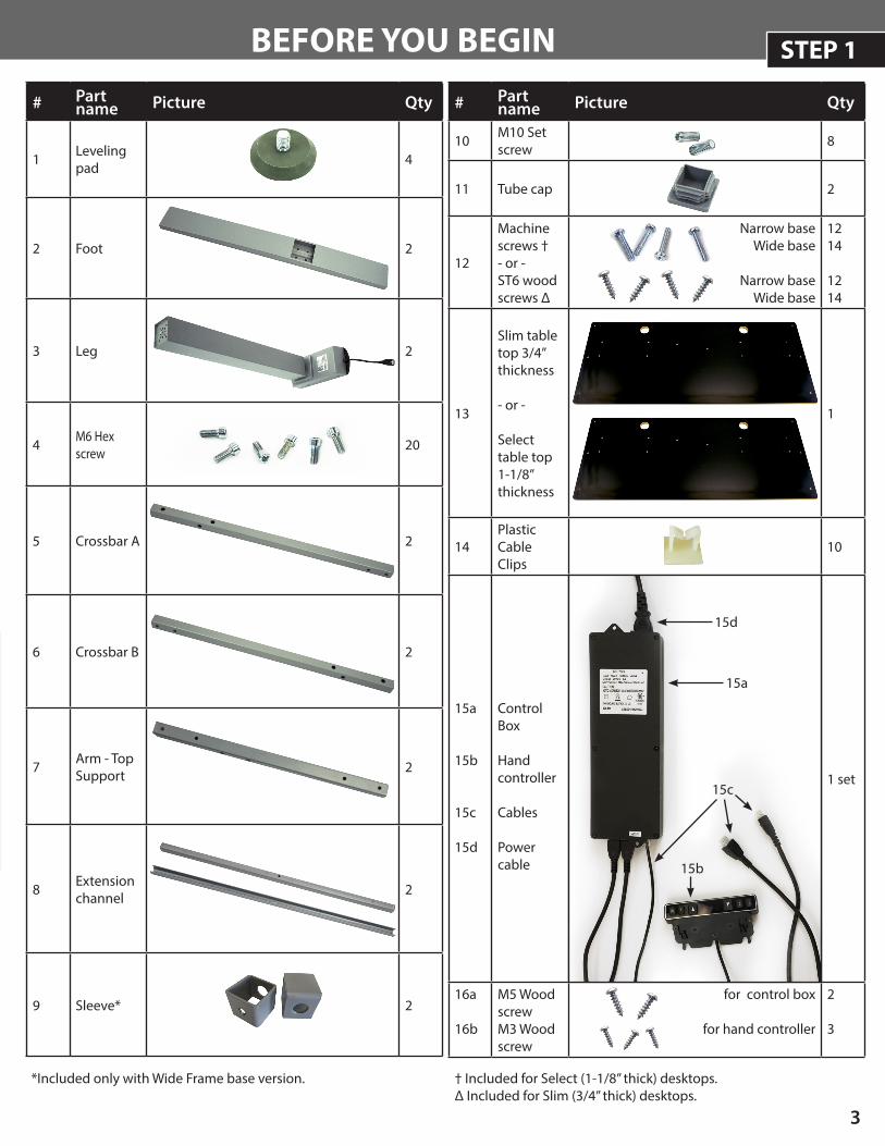
# Part name Picture Qty
10 M10 Set screw 8
11 Tube cap 2
12
Machine screws †- or -ST6 woodscrews ∆
Narrow baseWide base
Narrow baseWide base
1214
1214
13
Slim table top 3/4” thickness
- or -
Select table top1-1/8” thickness
1
14Plastic Cable Clips
10
15a
15b
15c
15d
Control Box
Hand controller
Cables
Power cable
1 set
16a
16b
M5 Wood screwM3 Wood screw
for control box
for hand controller
2
3
# Part name Picture Qty
1 Leveling pad 4
2 Foot 2
3 Leg 2
4 M6 Hex screw 20
5 Crossbar A 2
6 Crossbar B 2
7 Arm - Top Support 2
8 Extension channel 2
9 Sleeve* 2
BEFORE YOU BEGIN
15a
15b
15c
† Included for Select (1-1/8” thick) desktops.∆ Included for Slim (3/4” thick) desktops.
3
STEP 1
15d
*Included only with Wide Frame base version.
4
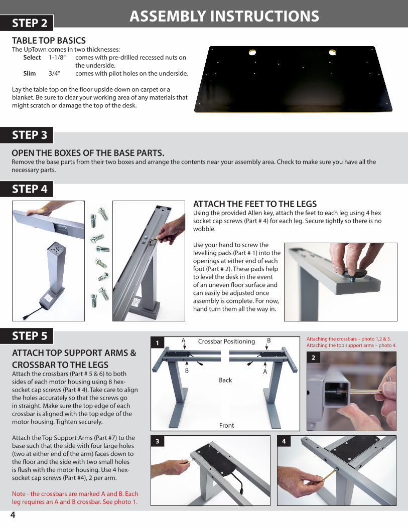
ASSEMBLY INSTRUCTIONSTABLE TOP BASICSThe UpTown comes in two thicknesses:
Select 1-1/8” comes with pre-drilled recessed nuts on the underside.
Slim 3/4” comes with pilot holes on the underside.
Lay the table top on the floor upside down on carpet or a blanket. Be sure to clear your working area of any materials that might scratch or damage the top of the desk.
OPEN THE BOXES OF THE BASE PARTS.Remove the base parts from their two boxes and arrange the contents near your assembly area. Check to make sure you have all the necessary parts.
ATTACH THE FEET TO THE LEGS Using the provided Allen key, attach the feet to each leg using 4 hex socket cap screws (Part # 4) for each leg. Secure tightly so there is no wobble.
Use your hand to screw the levelling pads (Part # 1) into the openings at either end of each foot (Part # 2). These pads help to level the desk in the event of an uneven floor surface and can easily be adjusted once assembly is complete. For now, hand turn them all the way in.
ATTACH TOP SUPPORT ARMS & CROSSBAR TO THE LEGSAttach the crossbars (Part # 5 & 6) to both sides of each motor housing using 8 hex-socket cap screws (Part # 4). Take care to align the holes accurately so that the screws go in straight. Make sure the top edge of each crossbar is aligned with the top edge of the motor housing. Tighten securely.
Attach the Top Support Arms (Part #7) to the base such that the side with four large holes (two at either end of the arm) faces down to the floor and the side with two small holes is flush with the motor housing. Use 4 hex-socket cap screws (Part #4), 2 per arm.
Note - the crossbars are marked A and B. Each leg requires an A and B crossbar. See photo 1.
Front
Back
A
AB
B1 Crossbar Positioning
STEP 2
STEP 3
STEP 4
STEP 5
2
3 4
Attaching the crossbars – photo 1,2 & 3. Attaching the top support arms – photo 4.
5
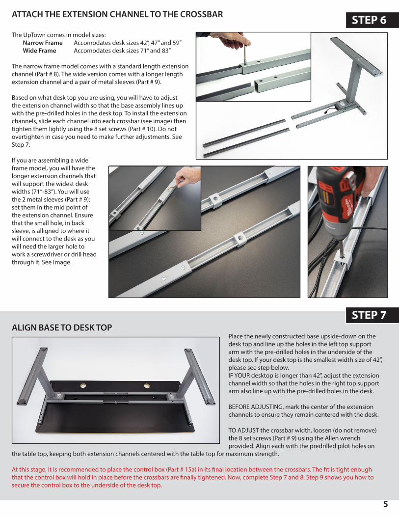
The UpTown comes in model sizes:Narrow Frame Accomodates desk sizes 42”, 47” and 59” Wide Frame Accomodates desk sizes 71” and 83”
The narrow frame model comes with a standard length extension channel (Part # 8). The wide version comes with a longer length extension channel and a pair of metal sleeves (Part # 9).
Based on what desk top you are using, you will have to adjust the extension channel width so that the base assembly lines up with the pre-drilled holes in the desk top. To install the extension channels, slide each channel into each crossbar (see image) then tighten them lightly using the 8 set screws (Part # 10). Do not overtighten in case you need to make further adjustments. See Step 7.
If you are assembling a wide frame model, you will have the longer extension channels that will support the widest desk widths (71”-83”). You will use the 2 metal sleeves (Part # 9); set them in the mid point of the extension channel. Ensure that the small hole, in back sleeve, is alligned to where it will connect to the desk as you will need the larger hole to work a screwdriver or drill head through it. See Image.
ALIGN BASE TO DESK TOPPlace the newly constructed base upside-down on the desk top and line up the holes in the left top support arm with the pre-drilled holes in the underside of the desk top. If your desk top is the smallest width size of 42”, please see step below.IF YOUR desktop is longer than 42”, adjust the extension channel width so that the holes in the right top support arm also line up with the pre-drilled holes in the desk.
BEFORE ADJUSTING, mark the center of the extension channels to ensure they remain centered with the desk.
TO ADJUST the crossbar width, loosen (do not remove) the 8 set screws (Part # 9) using the Allen wrench provided. Align each with the predrilled pilot holes on
the table top, keeping both extension channels centered with the table top for maximum strength.
At this stage, it is recommended to place the control box (Part # 15a) in its final location between the crossbars. The fit is tight enough that the control box will hold in place before the crossbars are finally tightened. Now, complete Step 7 and 8. Step 9 shows you how to secure the control box to the underside of the desk top.
STEP 6ATTACH THE EXTENSION CHANNEL TO THE CROSSBAR
STEP 7
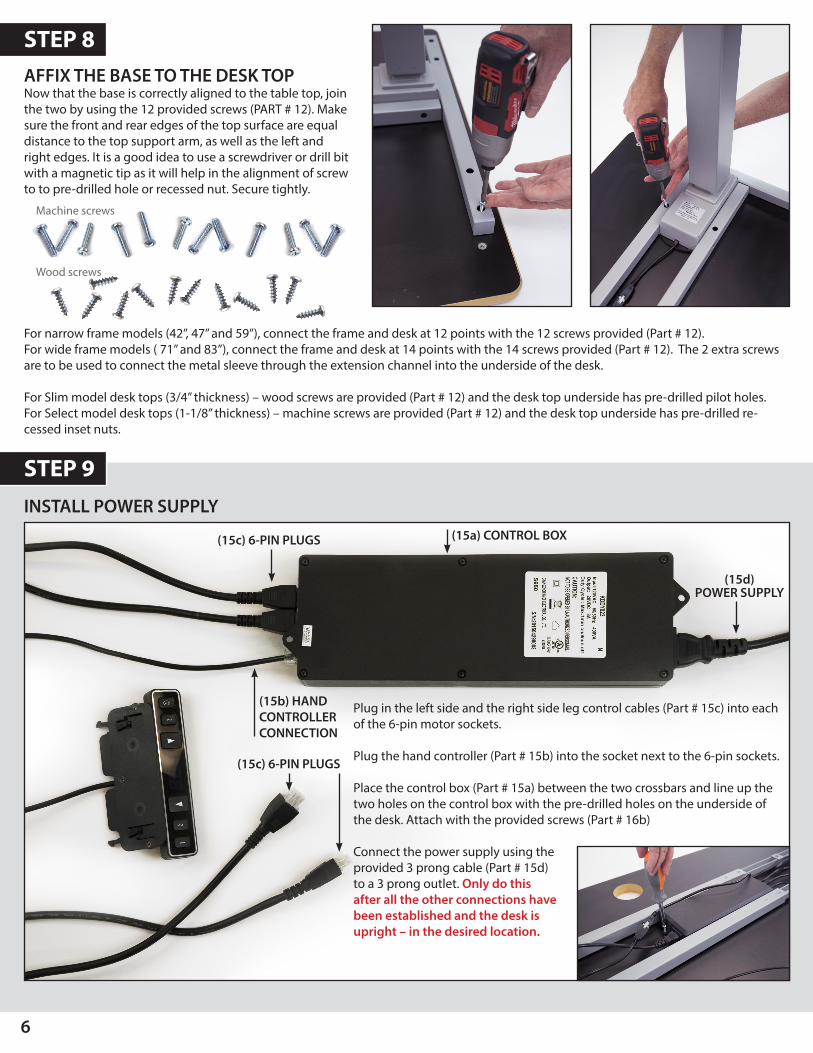
AFFIX THE BASE TO THE DESK TOPNow that the base is correctly aligned to the table top, join the two by using the 12 provided screws (PART # 12). Make sure the front and rear edges of the top surface are equal distance to the top support arm, as well as the left and right edges. It is a good idea to use a screwdriver or drill bit with a magnetic tip as it will help in the alignment of screw to to pre-drilled hole or recessed nut. Secure tightly.
STEP 8
For narrow frame models (42”, 47” and 59”), connect the frame and desk at 12 points with the 12 screws provided (Part # 12). For wide frame models ( 71” and 83”), connect the frame and desk at 14 points with the 14 screws provided (Part # 12). The 2 extra screws are to be used to connect the metal sleeve through the extension channel into the underside of the desk.
For Slim model desk tops (3/4” thickness) – wood screws are provided (Part # 12) and the desk top underside has pre-drilled pilot holes. For Select model desk tops (1-1/8” thickness) – machine screws are provided (Part # 12) and the desk top underside has pre-drilled re-cessed inset nuts.
INSTALL POWER SUPPLY
6
STEP 9
Plug in the left side and the right side leg control cables (Part # 15c) into each of the 6-pin motor sockets.
Plug the hand controller (Part # 15b) into the socket next to the 6-pin sockets.
Place the control box (Part # 15a) between the two crossbars and line up the two holes on the control box with the pre-drilled holes on the underside of the desk. Attach with the provided screws (Part # 16b)
Connect the power supply using the provided 3 prong cable (Part # 15d) to a 3 prong outlet. Only do this after all the other connections have been established and the desk is upright – in the desired location.
(15d) POWER SUPPLY
(15b) HAND CONTROLLER CONNECTION
(15c) 6-PIN PLUGS
(15c) 6-PIN PLUGS
(15a) CONTROL BOX
Machine screws
Wood screws
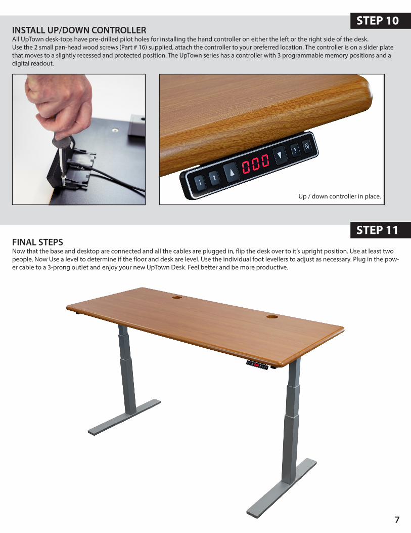
INSTALL UP/DOWN CONTROLLERAll UpTown desk-tops have pre-drilled pilot holes for installing the hand controller on either the left or the right side of the desk. Use the 2 small pan-head wood screws (Part # 16) supplied, attach the controller to your preferred location. The controller is on a slider plate that moves to a slightly recessed and protected position. The UpTown series has a controller with 3 programmable memory positions and a digital readout.
FINAL STEPSNow that the base and desktop are connected and all the cables are plugged in, flip the desk over to it’s upright position. Use at least two people. Now Use a level to determine if the floor and desk are level. Use the individual foot levellers to adjust as necessary. Plug in the pow-er cable to a 3-prong outlet and enjoy your new UpTown Desk. Feel better and be more productive.
Up / down controller in place.
STEP 10
STEP 11
7
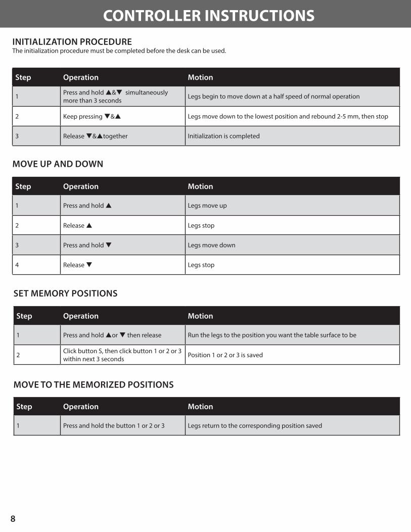
INITIALIZATION PROCEDUREThe initialization procedure must be completed before the desk can be used.
MOVE UP AND DOWN
Step Operation Motion
1 Press and hold p&q simultaneouslymore than 3 seconds
Legs begin to move down at a half speed of normal operation
2 Keep pressing q&p Legs move down to the lowest position and rebound 2-5 mm, then stop
3 Release q&ptogether Initialization is completed
Step Operation Motion
1 Press and hold p Legs move up
2 Release p Legs stop
3 Press and hold q Legs move down
4 Release q Legs stop
SET MEMORY POSITIONS
Step Operation Motion
1 Press and hold por q then release Run the legs to the position you want the table surface to be
2 Click button S, then click button 1 or 2 or 3 within next 3 seconds Position 1 or 2 or 3 is saved
MOVE TO THE MEMORIZED POSITIONS
Step Operation Motion
1 Press and hold the button 1 or 2 or 3 Legs return to the corresponding position saved
CONTROLLER INSTRUCTIONS
8
9
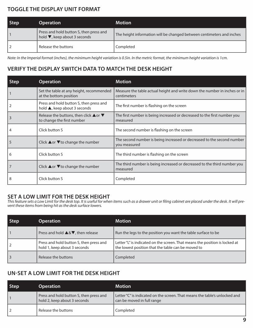
TOGGLE THE DISPLAY UNIT FORMAT
Step Operation Motion
1 Press and hold button S, then press and hold q, keep about 3 seconds The height information will be changed between centimeters and inches
2 Release the buttons Completed
Note: In the Imperial format (inches), the minimum height variation is 0.5in. In the metric format, the minimum height variation is 1cm.
VERIFY THE DISPLAY SWITCH DATA TO MATCH THE DESK HEIGHT
Step Operation Motion
1 Set the table at any height, recommended at the bottom position
Measure the table actual height and write down the number in inches or in centimeters
2 Press and hold button S, then press and hold p, keep about 3 seconds The first number is flashing on the screen
3 Release the buttons, then click por q to change the first number
The first number is being increased or decreased to the first number you measured
4 Click button S The second number is flashing on the screen
5 Click por qto change the numberThe second number is being increased or decreased to the second number you measured
6 Click button S The third number is flashing on the screen
7 Click por qto change the numberThe third number is being increased or decreased to the third number you measured
8 Click button S Completed
SET A LOW LIMIT FOR THE DESK HEIGHTThis feature sets a Low Limit for the desk top. It is useful for when items such as a drawer unit or filing cabinet are placed under the desk. It will pre-vent these items from being hit as the desk surface lowers.
Step Operation Motion
1 Press and hold p&q, then release Run the legs to the position you want the table surface to be
2 Press and hold button S, then press and hold 1, keep about 3 seconds
Letter “L” is indicated on the screen. That means the position is locked at the lowest position that the table can be moved to
3 Release the buttons Completed
UN-SET A LOW LIMIT FOR THE DESK HEIGHT
Step Operation Motion
1 Press and hold button S, then press and hold 2, keep about 3 seconds
Letter “C” is indicated on the screen. That means the table’s unlocked and can be moved in full range
2 Release the buttons Completed

TROUBLESHOOTING
FINAL TOUCHESAfter connecting all the cables and testing that the desk is working properly, you may want to invest in a cable manage-ment kit. This is a smart way to tidy up all the loose or draped cables. iMovR.com has a basic kit and an advanced kit.
Both are available at: www.imovr.com/cable-management-video
Symptom Handling
After connecting the power, press por q, the legs have no response.
Re-initialize the desk.
Check if the connections are correct.
Please contact your supplier.
After connecting the power, press and hold pand q, the legs have no response.
Check if the connections are correct.
Please contact your supplier.
The legs rise slowly.
Check to see if legs are perpendicular (at 90 degrees) to the desk-top and the floor. If the legs are splayed inward or outward, the motor will not operate at an optimum level.
Check the weight load on the table to see if it is excessive.
Confirm the line voltage is 110v.
One leg moves while the other does not.
Check the drive cable connection.
Check to see if legs are perpendicular (at 90 degrees) to the desk-top and the floor. If the legs are splayed inward or outward, the motor will not operate at an optimum level.
Please contact your supplier.
Legs only move down and don’t move up.Re-initialize the table.
Please contact your supplier.
Table slides down on its own.Check the weight load on the table to see if it is excessive.
Please contact your supplier.
The table goes into initialization frequently.Check the weight load on the table to see if it is excessive.
Please contact your supplier.
10
11
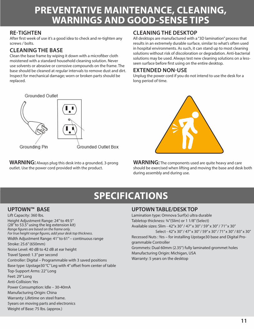
RE-TIGHTENAfter first week of use it’s a good idea to check and re-tighten any screws / bolts.
CLEANING THE BASE Clean the base frame by wiping it down with a microfiber cloth moistened with a standard household cleaning solution. Never use solvents or abrasive or corrosive compounds on the frame. The base should be cleaned at regular intervals to remove dust and dirt. Inspect for mechanical damage; worn or broken parts should be replaced.
CLEANING THE DESKTOP All desktops are manufactured with a “3D lamination” process that results in an extremely durable surface, similar to what’s often used in hospital environments. As such, it can stand up to most cleaning solutions without risk of discoloration or degradation. Anti-bacterial solutions may be used. Always test new cleaning solutions on a less-seen surface before first using on the entire desktop.
EXTENDED NON-USE Unplug the power cord if you do not intend to use the desk for a long period of time.
PREVENTATIVE MAINTENANCE, CLEANING, WARNINGS AND GOOD-SENSE TIPS
SPECIFICATIONS
WARNING: Always plug this desk into a grounded, 3-prong outlet. Use the power cord provided with the product.
WARNING: The components used are quite heavy and careshould be exercised when lifting and moving the base and desk both during assembly and during use.
UPTOWN™ BASELift Capacity: 360 lbs.Height Adjustment Range: 24” to 49.5” (28” to 53.5” using the leg extension kit)Range figures are based on the frame only. For true height range figures, add your desk top thickness.Width Adjustment Range: 41” to 61” – continuous rangeStroke: 25.6” (650mm)Noise Level: 40 dB to 42 dB at ear heightTravel Speed: 1.3” per secondController: Digital – Programmable with 3 saved positionsBase type: Upstage30 “C” Leg with 4” offset from center of tableTop-Support Arms: 22” LongFeet: 29” LongAnti-Collision: YesPower Consumption: Idle – 30-40mA Manufacturing Origin: ChinaWarranty: Lifetime on steel frame. 5years on moving parts and electronicsWeight of Base: 75 lbs. (approx.)
UPTOWN TABLE/DESK TOPLamination type: Omnova Surf(x) ultra durableTabletop thickness: ¾”(Slim) or 1 1/8” (Select)Available sizes: Slim - 42”x 30” / 47” x 30” / 59” x 30” / 71” x 30”
Select - 42”x 30” / 47” x 30” / 59” x 30” / 71” x 30” / 83” x 30”Recessed Nuts : Yes – for installing Upstage30 base and Digital Pro-grammable ControllerGrommets: Dual 60mm (2.35”) fully laminated grommet holesManufacturing Origin: Michigan, USAWarranty: 5 years on the desktop

WARRANTYThe iMovR Uptown warranty coverage includes a lifetime warranty on the steel frame, 5 years on the desktop and all other components.THIS WARRANTY only covers defects as specified herein and does not include defects or damages attributable to improper installation, misuse or normal surface weathering, or defects or damages caused by accidents or fire or other casualty or Acts of God, or any other causes, or occurrences beyond the manufacturer’s control. The exclusive remedial action provided for the customer hereunder shall be repair, restoration or replacement of the components as are found to be defective.
TABLE TOP: The replacement of new materials for those as may result in a color variance in comparison to the originally installed laminates due to slight color or texture changes by laminate manufacturers and is not indicative of a defect. IMovR reserves the right to substitute such laminates as are then being manufactured and is only obligated to match color and quality with such products as its manufacturing at the time of replacement.ELECTRIC BASE FRAME: New base frames may have paint defects or scratches on components that are hidden beneath the surface of the desk, which are normal. Painted components that are normally visible to sitting or standing users after installation of the table top, that arrive in damaged condition, will be replaced under this warranty if iMovR is notified before the component is installed.
THIS WARRANTY is limited to repair, restoration and/or replacement by iMovR of any defective unit provided the manufacturer: (a) receives a written, faxed or e-mailed notice of claim under this warranty, including sufficiently high resolution photographs that clearly show the nature of the damage, and (b) within 30 days after notice of claim, is in receipt of the defective unit at its place of business, unless this requirement is waived by iMovR. The manu-facturer will arrange for retrieval of the defective product via its carrier-of-choice. In some cases the manufacturer may elect not to retrieve the defective component, and may opt to send a replacement product based only on photographic evidence of warrantied defects. If upon receipt and inspection of the returned component it is determined that the damage was not due to a manufacturing flaw but rather one of the exempted reasons stated above, the costs of shipping the units to and from the manufacturer, plus the cost of the replacement component, shall be charged back to the customer.
LIMITATION OF LIABILITY: IT IS UNDERSTOOD AND AGREED THAT MANUFACTURER’S LIABILITY, WHETHER IN CONTRACT, IN TORT UNDER ANY WARRANTY, IN NEGLIGENCE OR OTHERWISE, SHALL NOT EXCEED THE RETURN OF THE AMOUNT OF PURCHASE PRICE FOR THE DEFECTIVE ITEM PAID BY PURCHASER AND UNDER NO CIRCUMSTANCES SHALL SELLER BE LIABLE FOR SPECIAL , INDIRECT OR CONSEQUENTIAL DAMAGES. NO ACTION, REGARDLESS OF FORM, ARISING OUT OF THE TRANSACTIONS UNDER THIS AGREEMENT MAY BE BROUGHT BY THE PURCHASER MORE THAN ONE YEAR AFTER THE CAUSE OF THE ACTION HAS ACCRUED.
SOME STATES DO NOT ALLOW LIMITATIONS ON HOW LONG AN IMPLIED WARRANTY LASTS, AND SOME STATES DO NOT ALLOW THE EXCLUSION OR LIMITA-TION OF INCIDENTAL OR CONSEQUENTIAL DAMAGES, SO THE ABOVE LIMITATIONS OR EXCLUSIONS HEREIN MAY NOT APPLY TO YOU. THIS WARRANTY GIVES YOU SPECIFIC LEGAL RIGHTS, AND YOU MAY ALSO HAVE OTHER RIGHTS, WHICH VARY, FROM STATE TO STATE. THIS WARRANTY GIVES YOU SPECIFIC LEGAL RIGHTS, AND YOU MAY ALSO HAVE OTHER RIGHTS, WHICH VARY, FROM STATE TO STATE. THIS WARRANTY APPLIES ONLY IN THE U.S. AND CANADA. WARRANTIES OUTSIDE OF THE UNITED STATES MAY VARY. PLEASE CONTACT YOUR LOCAL DEALER FOR DETAILS.
TO OBTAIN warranty repair please contact the iMovR Customer Care Department with the contact information provided on the back page of this manual.
IMovR Contact Information:Phone: (888) 208-6770 or (425) 999-3550Fax: (425) 999-3550E-mail: [email protected] Chat: www.iMovR.COMHours: See iMovR.com/hours
UpTown™
VERSION 9.25.15 IMOVR UPTOWN INSTALLATION MANUAL UT-REX-MANUAL