atdec spacedec workstation desk adjustable sd-pos-ha data sheet
TRANSCRIPT
Technical Specification SD-POS-HA
Dimensions
No portion of this document or any artwork contained herein should be reproduced in any way without the express written consent of Atdec Pty Ltd.Due to continuing product development, the manufacturer reserves the right to alter specifications without noticed. Published 09.03.11 ©
Display | POS Height Adjustable
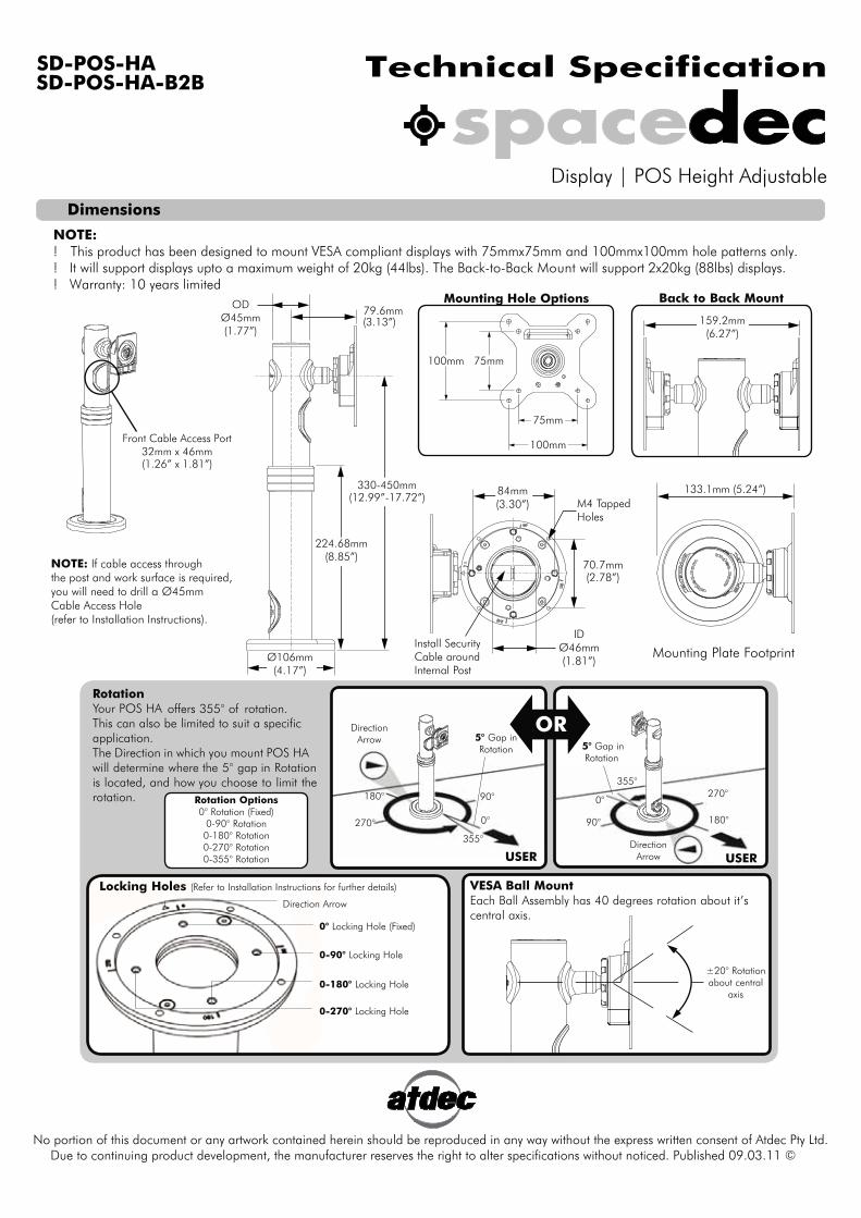
NOTE:! This product has been designed to mount VESA compliant displays with 75mmx75mm and 100mmx100mm hole patterns only.! It will support displays upto a maximum weight of 20kg (44lbs). The Back-to-Back Mount will support 2x20kg (88lbs) displays.! Warranty: 10 years limited
Front Cable Access Port32mm x 46mm(1.26” x 1.81”)
NOTE: If cable access throughthe post and work surface is required,you will need to drill a Ø45mmCable Access Hole(refer to Installation Instructions).
159.2mm(6.27”)
Back to Back Mount Mounting Hole Options ODØ45mm(1.77”)
330-450mm
79.6mm(3.13”)
224.68mm(8.85”)
Ø106mm(4.17”)
Mounting Plate F ootprint
133.1mm (5.24”)84mm (3.30”)
70.7mm (2.78”)
M4 T apped Holes
ID Ø46mm (1.81”)
Install Security Cable around Internal P ost
100mm
75mm
75mm100mm
R otation Y our POS HA offers 355° of rotation.This can also be limited to suit a specific application. The Direction in which you mount POS HA will determine where the 5° gap in R otation is located, and how you choose to limit the rotation.
OR
USER USER
5° Gap in R otation 5° Gap in
R otation
270°
180°
0°
90° 270°
180°
0°
90°
355°
355°
Direction Arrow
Direction Arrow
0° L ocking Hole ( F ixed)
0-180° L ocking Hole
0-270° L ocking Hole
0-90° L ocking Hole
Direction Arrow
Locking Holes ( R efer to Installation Instructions for further details)
±20° R otation about central
axis
VESA Ball Mount Each Ball Assembly has 40 degrees rotation about i t ’s central axis.
R otation Options 0° R otation ( F ixed)
0-90° R otation 0-180° R otation 0-270° R otation 0-355° R otation
SD-POS-HA-B2B
(12.99”-17.72”)
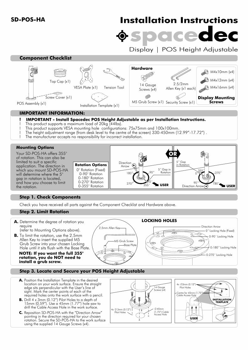
Component Checklist
2.5/2mmAllen Key (x1 each)
M4x12mm (x4)
M4x16mm (x4)Tension Tool
POS Assembly (x1)
Screw Cover (x1)
VESA Plate (x1)
Top Cap (x1)
M5 Grub Screw (x1) Security Screw (x1)
14 GaugeScrews (x4)
Installation Template (x1)
M4x10mm (x4)
90180
270 355
5 Gap inRotation 0
90 180
270355
0
5 Gapin Rotation
USER USER
DirectionArrow
Direction Arrow
LOCKING HOLES Direction Arrow
0 Locking Hole (Fixed)
0-90 Locking Hole
0-180 Locking Hole
0-270 Locking Hole
2.5mm Allen Key
Base PlateM5 Grub Screw
4x 3mm (0.12”)Pilot Holes
45mm(1.75”) CableAccess Hole
14 GaugeScrews (x4)
INSTALLATIONTEMPLATE
4x 3mm (0.12”)
USER
Installation InstructionsSD-POS-HA
Display | POS Height Adjustable
IMPORTANT INFORMATION:
Step 1. Check Components
Step 2. Limit Rotation
Step 3. Locate and Secure your POS Height Adjustable
! IMPORTANT - Install Spacedec POS Height Adjustable as per Installation Instructions. ! This product supports a maximum load of 20kg (44lbs).! This product supports VESA mounting hole configurations: 75x75mm and 100x100mm.
! The manufacturer accepts no responsibility for incorrect installation.
Display MountingScrews
Hardware
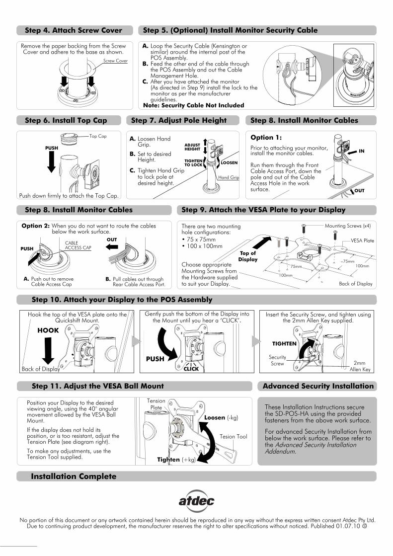
Your SD-POS-HA offers 355° of rotation. This can also be limited to suit a specific
which you mount SD-POS-HA will determine where the 5° gap in rotation is located, and how you choose to limit the rotation.
Determine the degree of rotation youA.require(refer to Mounting Options above).To limit the rotation, use the 2.5mm B.Allen Key to insert the supplied M5Grub Screw into your chosen LockingHole until it sits flush with the Base Plate.NOTE: If you want the full 355° rotation, you do NOT need to install a grub screw.
Mounting Options
Rotation Options0° Rotation (Fixed)
0-90° Rotation0-180° Rotation0-270° Rotation0-355° Rotation
OR
Position the Installation Template in the desired A.location on your work surface. Ensure the straight edge sits perpendicular with the User’s line of sight. Mark the center points of each of the required holes onto the work surface with a pencil.Drill 4 x 3mm (0.12”) Pilot Holes to a depth of B.15mm (0.59”). Use a 45mm (1.77”) hole saw to drill the Cable Access Hole in the work surface.Reposition SD-POS-HA with the “Direction Arrow” C.pointing in the direction required for your chosen rotation. Secure the SD-POS-HA to the work surfaceusing the supplied 14 Gauge Screws (x4).
Check you have received all parts against the Component Checklist and Hardware above.
Pilot Holes
application. The direction in
Centre for 45mm (1.75”)Cable Access Hole
! The height adjustment range (from desk level to the centre of the screen) 330-450mm (12.99”-17.72”) .
Tighte
Allen Key
Gently push the bottom of the Display into
Back of Display
Screw Cover
Top Cap
PUSHIN
OUT
Hand Grip
Push out to remove A.Cable Access Cap
CABLEACCESS CAPPUSH
Pull cables out through B.Rear Cable Access Port.
Installation Complete
Step 6. Install Top Cap
CNo portion of this document or any artwork contained herein should be reproduced in any way without the express written consent Atdec Pty Ltd.
Due to continuing product development, the manufacturer reserves the right to alter specifications without noticed. Published 01.07.10
Step 4. Attach Screw Cover
Step 8. Install Monitor Cables
Step 10. Attach your Display to the POS Assembly
Step 11. Adjust the VESA Ball Mount
Remove the paper backing from the ScrewCover and adhere to the base as shown.
Loop the Security Cable (Kensington or A.similar) around the internal post of the POS Assembly.Feed the other end of the cable through B.the POS Assembly and out the Cable Management Hole.After you have attached the monitorC.(As directed in Step 9) install the lock to the monitor as per the manufacturer guidelines.
Note: Security Cable Not Included
Step 5. (Optional) Install Monitor Security Cable
Step 8. Install Monitor Cables
Push down firmly to attach the Top Cap.
Prior to attaching your monitor, install the monitor cables.
Run them through the Front Cable Access Port, down the pole and out of the CableAccess Hole in the work
Loosen HandA.
Set to desiredB.
Tighten Hand Grip C.to lock pole atdesired height.
LOOSENTIGHTENTO LOCK
ADJUSTHEIGHT
Option 2: When you do not want to route the cables
Step 9. Attach the VESA Plate to your Display
These Installation Instructions secure the SD-POS-HA using the provided fasteners from the above work surface.
For advanced Security Installation from below the work surface. Please refer to the Advanced Security Installation Addendum.
Advanced Security Installation
OUT
There are two mounting hole configurations:��������������������
Choose appropriate Mounting Screws from the Hardware supplied to suit your Display.
Hook the top of the VESA plate onto the Quickshift Mount. the Mount until you hear a ‘CLICK’
Insert the Security Screw, and tighten using the 2mm Allen Key supplied.
Position your Display to the desired viewing angle, using the 40° angular movement allowed by the VESA Ball Mount.
If the display does not hold its position, or is too resistant, adjust the Tension Plate (see diagram right).
To make any adjustments, use the Tension Tool supplied.
Top ofDisplay
Mounting Screws (x4)
VESA Plate
Back of Display
����100mm����
100mm
HOOK
CLICK
PUSH SecurityScrew
TIGHTEN
2mm
n (+kg)
Loosen (-kg)
TensionPlate
Tesion Tool
Option 1:
surface.
Step 7. Adjust Pole Height
Grip.
Height.
below the work surface.
Advanced Security Installation Addendum
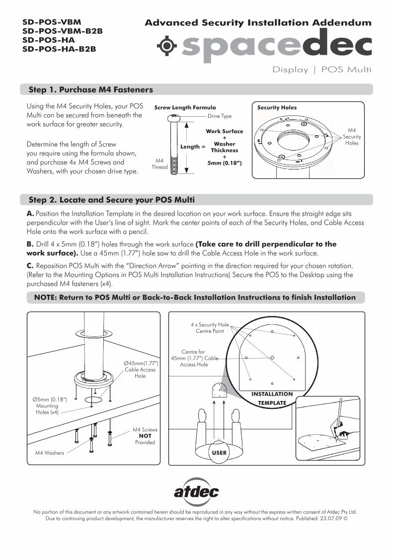
Step 1. Purchase M4 Fasteners
Using the M4 Security Holes, your POS Multi can be secured from beneath the work surface for greater security.
Determine the length of Screw you require using the formula shown, and purchase 4x M4 Screws and Washers, with your chosen drive type.
Screw Length Formula Security Holes
A. Position the Installation Template in the desired location on your work surface. Ensure the straight edge sits perpendicular with the User’s line of sight. Mark the center points of each of the Security Holes, and Cable Access Hole onto the work surface with a pencil. B. Drill 4 x 5mm (0.18”) holes through the work surface (Take care to drill perpendicular to the work surface). Use a 45mm (1.77”) hole saw to drill the Cable Access Hole in the work surface.
C. Reposition POS Multi with the “Direction Arrow” pointing in the direction required for your chosen rotation. (Refer to the Mounting Options in POS Multi Installation Instructions) Secure the POS to the Desktop using thepurchased M4 fasteners (x4).
Step 2. Locate and Secure your POS Multi
No portion of this document or any artwork contained herein should be reproduced in any way without the express written consent of Atdec Pty Ltd. Due to continuing product development, the manufacturer reserves the right to alter specifications without notice. Published: 23.07.09 ©
NOTE: Return to POS Multi or Back-to-Back Installation Instructions to finish Installation
Work Surface+
WasherThickness
+5mm (0.18”)
Length =
M4Thread
M4SecurityHoles
4 x Security Hole Centre Point
Centre for 45mm (1.77”) Cable
Access HoleØ45mm(1.77”) Cable Access
Hole
M4 Screws NOT
Provided
M4 Washers
Ø5mm (0.18”)Mounting Holes (x4)
Drive Type
INSTALLATION
TEMPLATE
USER
Display | POS Multi
SD-POS-VBMSD-POS-VBM-B2BSD-POS-HASD-POS-HA-B2B