imovr thermodesk elite adjustable-height standing desk installation manual
TRANSCRIPT
1
3D-Adjustable Sit/Stand Desk System
INSTALLATION MANUAL
VERSION 6.30.15
CONGRATULATIONS on your purchase of an Elite adjustable-height desk system! We designed this product to be as easy as possible to assemble, but if you have any questions during the assembly process please contact our Customer Care team at (888) 208-6770, or
NOTE: Should you be installing your own table top on the ELITE frame, be sure to drill pilot holes before inserting wood screws. The wood screws supplied with the ELITE base should work with most table tops. It is critical to pay attention to the available depth for pilot holes so as not to damage the lamination of the table top surface.
Please Read This
2
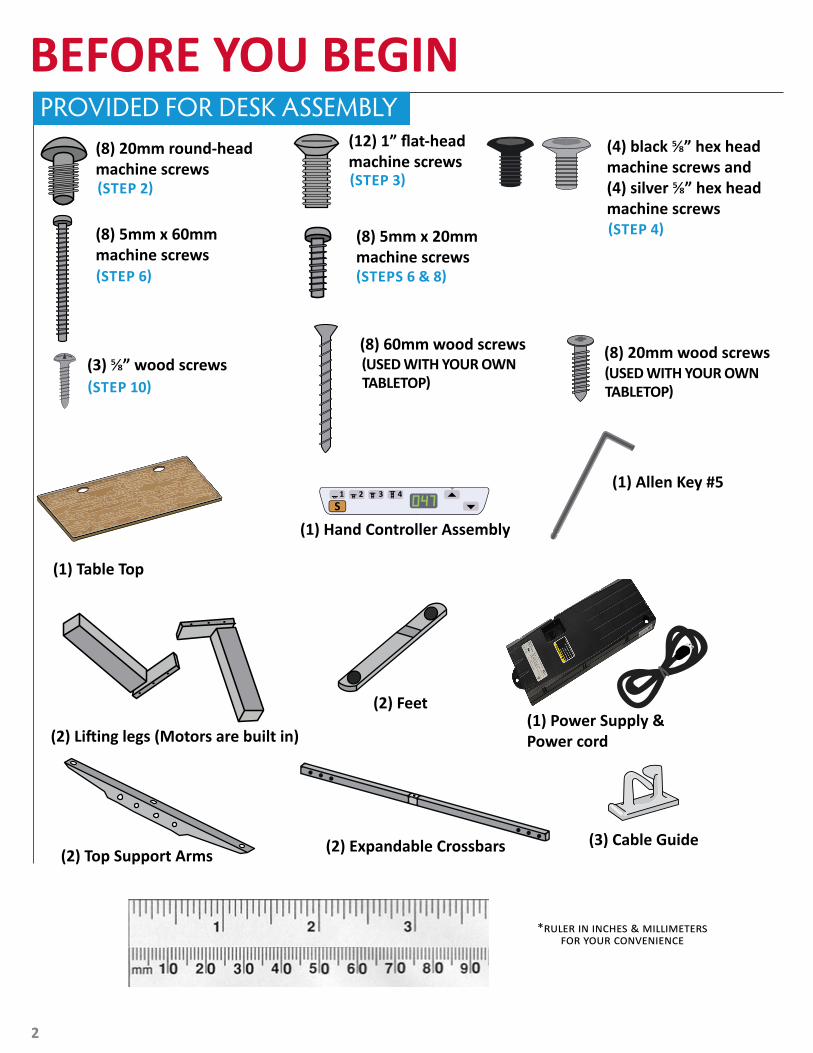
BEFORE YOU BEGINPROVIDED FOR DESK ASSEMBLY
(1) Allen Key #5
(3) Cable Guide(2) Top Support Arms
(2) Lifting legs (Motors are built in)
(2) Feet
(1) Table Top
(8) 20mm round-headmachine screws
(12) 1” flat-headmachine screws
(8) 20mm wood screws(3) ⅝” wood screws
(8) 60mm wood screws
(8) 5mm x 60mm machine screws
(8) 5mm x 20mm machine screws
(1) Hand Controller Assembly
(4) black ⅝” hex head machine screws and (4) silver ⅝” hex head machine screws
(1) Power Supply & Power cord
(STEP 2)
(USED WITH YOUR OWN TABLETOP)
(STEPS 6 & 8)
(STEP 4)
(STEP 10)
(STEP 6)
(USED WITH YOUR OWN TABLETOP)
(STEP 3)
(2) Expandable Crossbars
*ruler in inches & millimeters for your convenience
3
ASSEMBLY INSTRUCTIONS
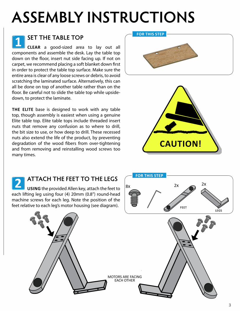
CLEAR a good-sized area to lay out all components and assemble the desk. Lay the table top down on the floor, insert nut side facing up. If not on carpet, we recommend placing a soft blanket down first in order to protect the table top surface. Make sure the entire area is clear of any loose screws or debris, to avoid scratching the laminated surface. Alternatively, this can all be done on top of another table rather than on the floor. Be careful not to slide the table top while upside-down, to protect the laminate.
THE ELITE base is designed to work with any table top, though assembly is easiest when using a genuine Elite table top. Elite table tops include threaded insert nuts that remove any confusion as to where to drill, the bit size to use, or how deep to drill. These recessed nuts also extend the life of the product, by preventing degradation of the wood fibers from over-tightening and from removing and reinstalling wood screws too many times.
1 SET THE TABLE TOPFOR THIS STEP
USING the provided Allen key, attach the feet to each lifting leg using four (4) 20mm (0.8”) round-head machine screws for each leg. Note the position of the feet relative to each leg’s motor housing (see diagram).
2 ATTACH THE FEET TO THE LEGS FOR THIS STEP
CAUTION!
MOTORS ARE FACINGEACH OTHER
8x 2x 2x
feetlegs
4
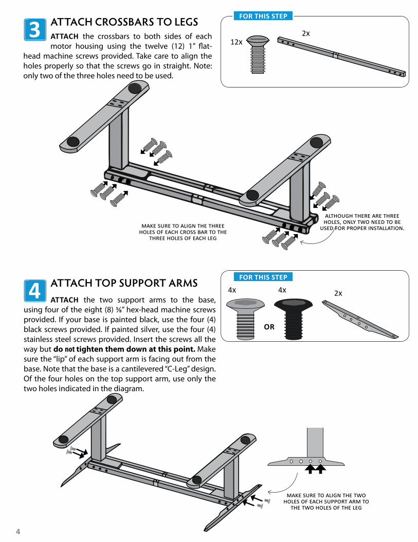
ATTACH the crossbars to both sides of each motor housing using the twelve (12) 1” flat-
head machine screws provided. Take care to align the holes properly so that the screws go in straight. Note: only two of the three holes need to be used.
3 ATTACH CROSSBARS TO LEGS FOR THIS STEP
ATTACH the two support arms to the base, using four of the eight (8) ⅝” hex-head machine screws provided. If your base is painted black, use the four (4) black screws provided. If painted silver, use the four (4) stainless steel screws provided. Insert the screws all the way but do not tighten them down at this point. Make sure the “lip” of each support arm is facing out from the base. Note that the base is a cantilevered “C-Leg” design. Of the four holes on the top support arm, use only the two holes indicated in the diagram.
4 ATTACH TOP SUPPORT ARMS FOR THIS STEP
although there are three holes, only two need to be
used for proper installation.
OR
12x
4x 2x4x
2x
make sure to align the three holes of each cross bar to the
three holes of each leg
make sure to align the two holes of each support arm to
the two holes of the leg

5
PLACE the base down on the table top and line up the holes in the left top support arm with the recessed nuts in the table top. If your desktop is 48” wide you can proceed to Step 6. IF YOUR desktop is longer than 48” then the next step is to adjust the crossbar width so that the holes in the right top support arm also line up with the recessed nuts in the table top.
BEFORE ADJUSTING, mark the center holes of the C-Channel extensions of the crossbars to ensure proper adjustment.
TO ADJUST the crossbar width, loosen (do not remove) the two set screws on either side of the center holes of the crossbars, using the #5 Allen key. Slide the legs apart to reveal the correct number of holes for your table top size, keeping the unpainted “C channel” tube centered.
FOR EXAMPLE, if installing for a 60” table top, slide the C channel tube so as to expose one additional hole left-of-center, and one additional hole right-of-center, to reveal a total of three holes. The original exposed hole must remain in the center, with an equal number of newly-exposed holes to the right and left.
*If the center hole does not remain in the center position, step 6 will not work!
5 ALIGN BASE TO TABLE TOP FOR THIS STEP
THE MACHINE screws for attaching the base are located in a separate bag from the base screws. Use the eight (8) 5mm x 60mm machine screws to attach the crossbars to the table top. Use six (6) 5mm x 20mm machine screws to attach the top support arms to the table.
6 AFFIX BASE TO TABLE TOP
8x
FOR THIS STEP
not provided
the set screws are located between the crossbars.
the middle hole on the c channel
extensions should remain
centered as you adjust the legs.
6x
Marker/pen to mark center hole(not provided)
base screws
30” x 48” 130” x 60” 330” x 72” 7
30” x 83” 9
TABLE TOP SIZE# OF HOLES EXPOSED
IN EXTENSION BARS
6
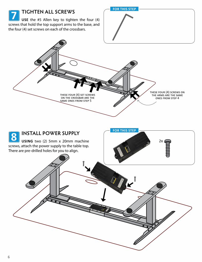
USE the #5 Allen key to tighten the four (4) screws that hold the top support arms to the base, and the four (4) set screws on each of the crossbars.
7 TIGHTEN ALL SCREWS FOR THIS STEP
USING two (2) 5mm x 20mm machine screws, attach the power supply to the table top. There are pre-drilled holes for you to align.
8 INSTALL POWER SUPPLY FOR THIS STEP
these four (4) set screws on the crossbar are the same ones from step 5
these four (4) screws on the arms are the same
ones from step 4
2x
7-pin socket
7
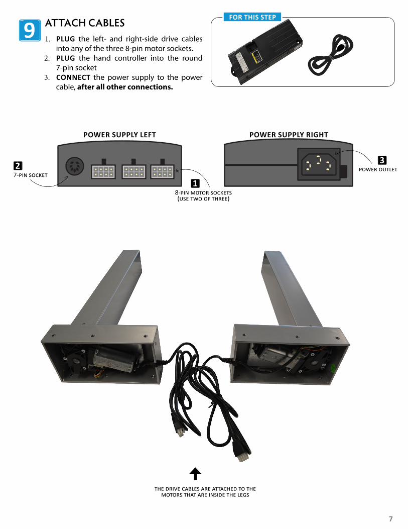
1. PLUG the left- and right-side drive cables into any of the three 8-pin motor sockets.
2. PLUG the hand controller into the round 7-pin socket
3. CONNECT the power supply to the power cable, after all other connections.
9 ATTACH CABLES FOR THIS STEP
7-pin socket
8-pin motor sockets(use two of three)
1
2 power outlet3
POWER SUPPLY LEFT POWER SUPPLY RIGHT
the drive cables are attached to the motors that are inside the legs
8
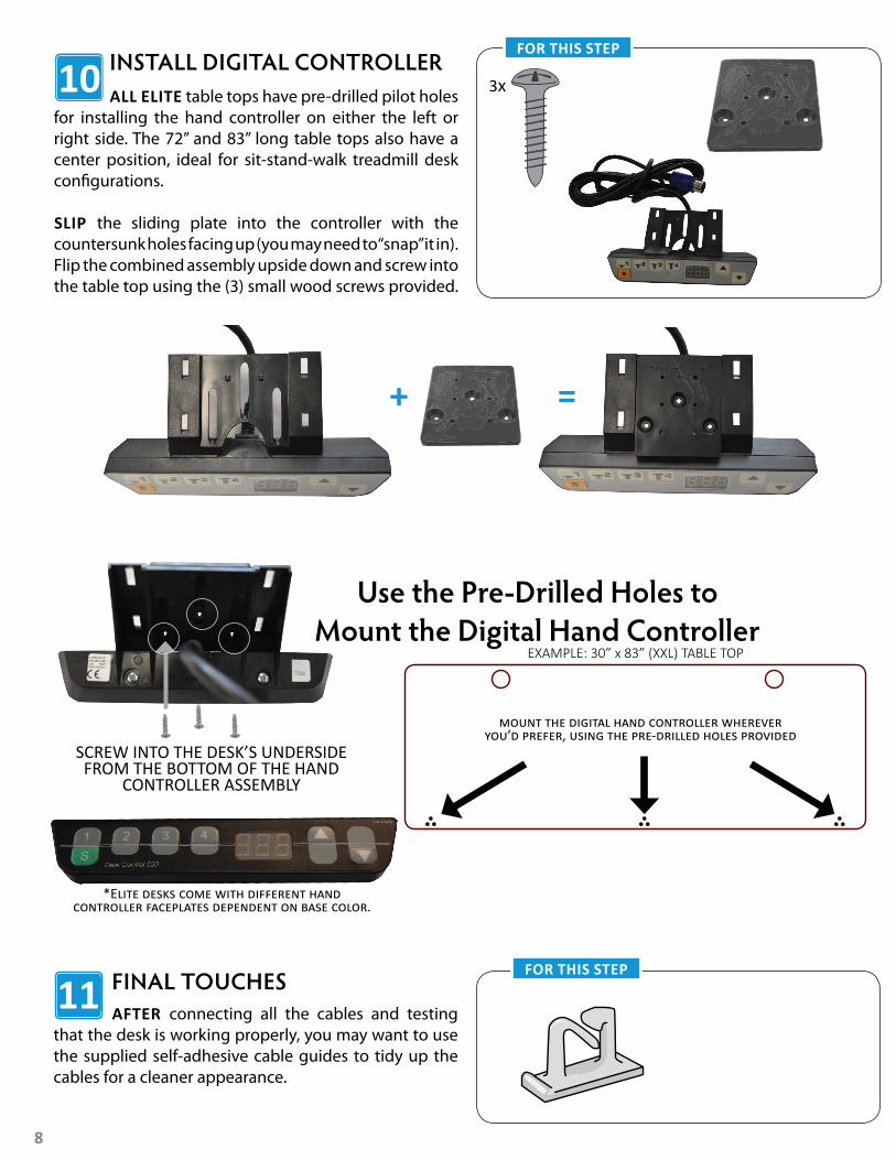
ALL ELITE table tops have pre-drilled pilot holes for installing the hand controller on either the left or right side. The 72” and 83” long table tops also have a center position, ideal for sit-stand-walk treadmill desk configurations.
SLIP the sliding plate into the controller with the countersunk holes facing up (you may need to “snap” it in). Flip the combined assembly upside down and screw into the table top using the (3) small wood screws provided.
INSTALL DIGITAL CONTROLLERFOR THIS STEP
10 3x
SCREW INTO THE DESK’S UNDERSIDE FROM THE BOTTOM OF THE HAND
CONTROLLER ASSEMBLY
+ =
*Elite desks come with different hand controller faceplates dependent on base color.
Use the Pre-Drilled Holes toMount the Digital Hand Controller
AFTER connecting all the cables and testing that the desk is working properly, you may want to use the supplied self-adhesive cable guides to tidy up the cables for a cleaner appearance.
11 FINAL TOUCHES FOR THIS STEP
EXAMPLE: 30” x 83” (XXL) TABLE TOP
mount the digital hand controller wherever you’d prefer, using the pre-drilled holes provided
9
USER INSTRUCTIONSMAKE sure there is nothing blocking the travel of the desk in the space where it will operate. After the desk is assembled and plugged into the power outlet, the controller will need to be initialized. To do so, press and hold the “Down” button until the desk descends completely, then “bounces” and ascends slightly. Doing so allows the control unit to register the lowest elevation before use.
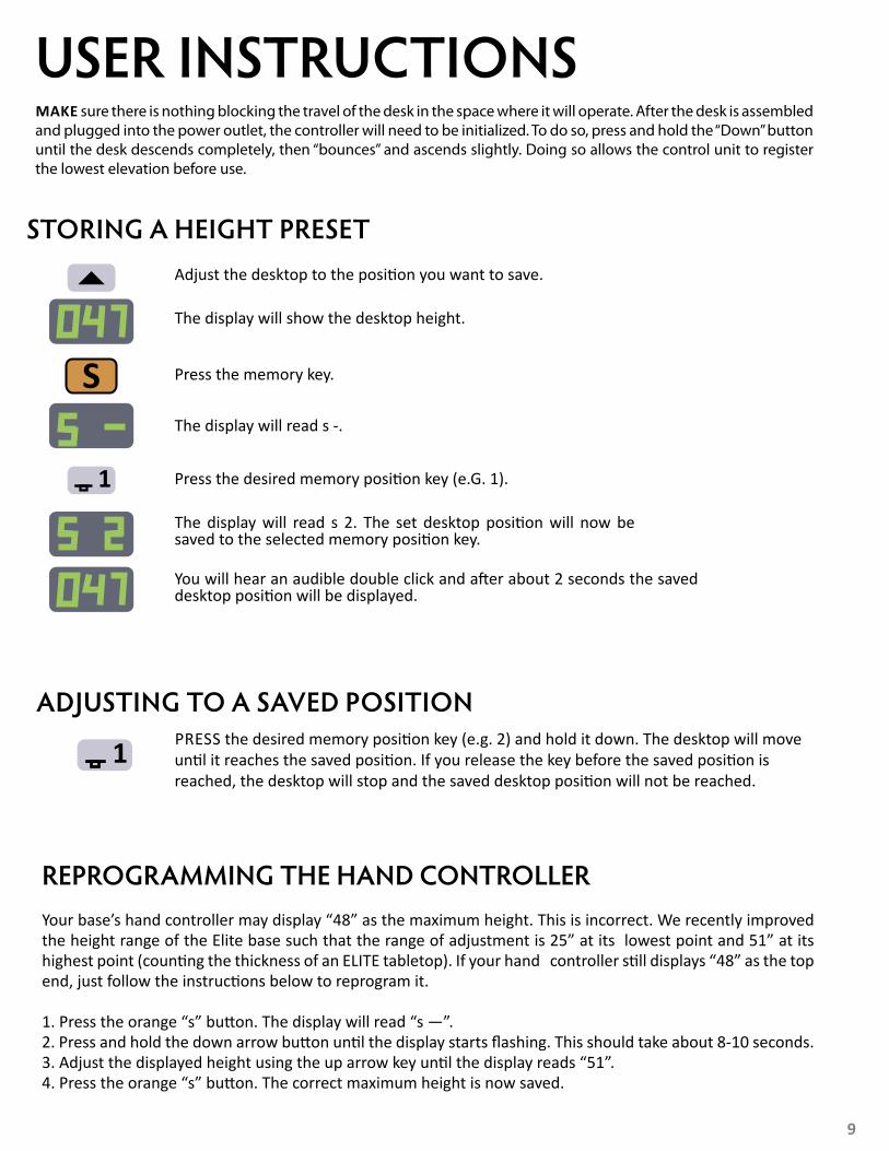
STORING A HEIGHT PRESET
ADJUSTING TO A SAVED POSITION
Adjust the desktop to the position you want to save.
The display will show the desktop height.
Press the memory key.
The display will read s 2. The set desktop position will now be saved to the selected memory position key.
You will hear an audible double click and after about 2 seconds the saved desktop position will be displayed.
PRESS the desired memory position key (e.g. 2) and hold it down. The desktop will move until it reaches the saved position. If you release the key before the saved position is reached, the desktop will stop and the saved desktop position will not be reached.
REPROGRAMMING THE HAND CONTROLLERYour base’s hand controller may display “48” as the maximum height. This is incorrect. We recently improved the height range of the Elite base such that the range of adjustment is 25” at its lowest point and 51” at its highest point (counting the thickness of an ELITE tabletop). If your hand controller still displays “48” as the top end, just follow the instructions below to reprogram it.
1. Press the orange “s” button. The display will read “s —”.2. Press and hold the down arrow button until the display starts flashing. This should take about 8-10 seconds.3. Adjust the displayed height using the up arrow key until the display reads “51”.4. Press the orange “s” button. The correct maximum height is now saved.
Press the desired memory position key (e.G. 1).
The display will read s -.

10
MANUAL RESET
CONTAINER- AND SHELF-STOP POSITIONS
IF THE actual desktop position no longer corresponds to the height displayed, you can reset the lowest desktop position to the minimum height.
PRESS and hold the desktop down key until the desktop has reached the lowest position (programmed desktop position).
PRESS and hold the desktop down key again. After about 5 seconds, the desktop will slowly move further down until it reaches the absolute lowest desktop position possible (25 inches).RELEASE the desktop down key. The electric height-adjustable desk can again be used normally.
NOTE: The Container- and Shelf Stop Positions feature is not enabled during reset. Ensure that the area below the desk is completely clear before performing a reset.
THESE TWO features can be used to limit the movement area of the desktop (e.g. if a tall trash can is placed underneath the desktop). A container stop position can be defined in the lower half of the movement area, a shelf stop position in the upper half. If a container stop position is set, this position will be the lower limit position. If a shelf stop position is set, this position will be the new upper limit position.
MOVE the desktop to a position where the container stop or shelf stop position shall be stored. PRESS S for 10 seconds. The Control Unit will click twice when the container stop position is stored.
TO STORE A CONTAINER STOP / SHELF STOP POSITION:
MOVE the desktop to any position in the lower half to deactivate the container stop. Move the desktop to any position in the upper half to deactivate the shelf stop.PRESS S for 10 seconds. The Control Unit will click once when the container or shelf stop position is deactivated.
TO DEACTIVATE THE CONTAINER STOP / SHELF STOP POSITION:
PREVENTATIVE MAINTENANCE & CLEANINGAFTER first week of use: Tighten down all screws and bolts.CLEANING the base: Clean the base frame by wiping it down with a microfiber cloth moistened with a standard household cleaning solution. Never use solvents or abrasive or corrosive compounds on the frame. The base should be cleaned at regular intervals to remove dust and dirt, and inspected for mechanical damage, wear and breaks - worn out parts should be replaced.
CLEANING the table top: All table tops are manufactured with a “3D lamination” process that results in an extremely durable surface, similar to what is often used in hospital environments. As such it can stand up to most cleaning solutions without risk of discoloration or degradation. Anti-bacterial solutions may be used. Always test new cleaning solutions on a less-seen surface first before using on the entire table top.
EXTENDED non-use: Unplug the power cord if you do not intend to use the desk for a long period of time.
11
TROUBLESHOOTINGIF THE table cannot be raised or lowered, check the cable connection between the control unit and the motor units (leg system), the handset and the control unit, as well as between the control unit and the power outlet.
IF THE table still does not respond, the control unit may have triggered the overheating protection or the intermittency protection. Please wait for at least nine minutes and try again before proceeding with other measures.
IF THE control unit has been replaced - or unplugged for a substantial period of time - it must first be reset before it can be used:
1. LOWER the table to its lowest position by holding the “Down” button on the handset.
2. PRESS the “Down” button on the handset again and hold it down until the table first moves fractions of an inch downwards and then fractions of an inch back up again. The control unit has now registered the lowest elevation and is ready to use.
3. SHOULD the table still not work as intended after taking these measures, please contact the iMovR Customer Care Department for assistance.
WARRANTYTHE IMOVR ELITE warranty coverage includes 20 years on the steel frame, 10 years on moving parts, 5 years on table tops, and 2 years on the electronics. The following limitations apply:
THIS WARRANTY only covers defects as specified herein and does not include defects or damages attributable to improper installation, misuse or normal surface weathering, or defects or damages caused by accidents or fire or other casualty or Acts of God, or any other causes or occurrences beyond the manufacturer’s control. The exclusive remedial action provided for the customer hereunder shall be repair, restoration or replacement of the components as are found to be defective.
TABLE TOP: The replacement of new materials for those as may be defective may result in a color variance in comparison to the originally installed laminates due to slight color or texture changes by laminate manufacturers and is not indicative of a defect. iMovR reserves the right to substitute such laminates as are then being manufactured and is only obligated to match color and quality with such products as it is manufacturing at the time of replacement. Electric base frame: New base frames may have paint defects or scratches on components that are hidden beneath the surface of the desk, which are normal. Painted components that are normally visible to sitting or standing users after installation of the table top, that arrive in damaged condition, will be replaced under this warranty if iMovR is notified before the component is installed.
THIS WARRANTY is limited to repair, restoration and/or replacement by iMovR of any defective unit provided the manufacturer: (a) receives a written, faxed or emailed notice of claim under this warranty, including sufficiently high resolution photographs that clearly show the nature of the damage, and (b) within 30 days after notice of claim, is in receipt of the defective unit at its place of business, unless this requirement is waived by iMovR. The manufacturer will arrange for retrieval of the defective product via its carrier-of-choice. In some cases the manufacturer may elect not to retrieve the defective component, and may opt to send a replacement product based only on photographic evidence of warrantied defects. If upon receipt and inspection of the returned component it is determined that the damage was not due to a manufacturing flaw but rather one of the exempted reasons stated above, the costs of shipping the units to and from the manufacturer, plus the cost of the replacement component, shall be charged back to the customer.
LIMITATION OF LIABILITY: IT IS UNDERSTOOD AND AGREED THAT MANUFACTURER’S LIABILITY, WHETHER IN CONTRACT, IN TORT UNDER ANY WARRANTY, IN NEGLIGENCE OR OTHERWISE, SHALL NOT EXCEED THE RETURN OF THE AMOUNT OF PURCHASE PRICE FOR THE DEFECTIVE ITEM PAID BY PURCHASER AND UNDER NO CIRCUMSTANCES SHALL SELLER BE LIABLE FOR SPECIAL, INDIRECT OR CONSEQUENTIAL DAMAGES. NO ACTION, REGARDLESS OF FORM, ARISING OUT OF THE TRANSACTIONS UNDER THIS AGREEMENT MAY BE BROUGHT BY THE PURCHASER MORE THAN ONE YEAR AFTER THE CAUSE OF ACTION HAS ACCRUED.
SOME states do not allow limitations on how long an implied warranty lasts, and some states do not allow the exclusion or limitation of incidental or consequential damages, so the above limitations or exclusions herein may not apply to you. This warranty gives you specific legal rights, and you may also have other rights, which vary, from state to state.
TO OBTAIN warranty repair please contact the iMovR Customer Care department with the contact information on the back page.
12
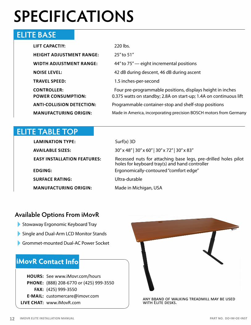
SPECIFICATIONSLIFT CAPACTIY: 220 lbs.
NOISE LEVEL: 42 dB during descent, 46 dB during ascent
HEIGHT ADJUSTMENT RANGE: 25” to 51”
WIDTH ADJUSTMENT RANGE: 44” to 75” — eight incremental positions
TRAVEL SPEED: 1.5 inches-per-second
CONTROLLER: Four pre-programmable positions, displays height in inches
MANUFACTURING ORIGIN: Made in America, incorporating precision BOSCH motors from Germany
LAMINATION TYPE: Surf(x) 3D
AVAILABLE SIZES: 30” x 48” | 30” x 60” | 30” x 72” | 30” x 83”
iMovR Contact Info
HOURS: See www.iMovr.com/hoursPHONE: (888) 208-6770 or (425) 999-3550
FAX: (425) 999-3550E-MAIL: [email protected]
LIVE CHAT: www.iMovR.com
Available Options From iMovRStowaway Ergonomic Keyboard Tray
Single and Dual-Arm LCD Monitor Stands
Grommet-mounted Dual-AC Power Socket
any brand of walking treadmill may be used with Elite desks.
ELITE BASE
ELITE TABLE TOP
POWER CONSUMPTION: 0.375 watts on standby; 2.8A on start-up; 1.4A on continuous lift
ANTI-COLLISION DETECTION: Programmable container-stop and shelf-stop positions
SURFACE RATING: Ultra-durable
EDGING: Ergonomically-contoured “comfort edge”
MANUFACTURING ORIGIN: Made in Michigan, USA
EASY INSTALLATION FEATURES: Recessed nuts for attaching base legs, pre-drilled holes pilot holes for keyboard tray(s) and hand controller
IMOVR ELITE INSTALLATION MANUAL PART NO. DO-IM-OE-INST