upscaling permeability for fractured concrete: meso-macro … · 2020-04-18 · upscaling...
TRANSCRIPT

HAL Id: hal-01006624https://hal.archives-ouvertes.fr/hal-01006624
Submitted on 16 Jun 2014
HAL is a multi-disciplinary open accessarchive for the deposit and dissemination of sci-entific research documents, whether they are pub-lished or not. The documents may come fromteaching and research institutions in France orabroad, or from public or private research centers.
L’archive ouverte pluridisciplinaire HAL, estdestinée au dépôt et à la diffusion de documentsscientifiques de niveau recherche, publiés ou non,émanant des établissements d’enseignement et derecherche français ou étrangers, des laboratoirespublics ou privés.
Upscaling permeability for fractured concrete:meso-macro numerical approach coupled to strong
discontinuitiesXavier Jourdain, Jean-Baptiste Colliat, Caroline de Sa, Farid Benboudjema,
Fabrice Gatuingt
To cite this version:Xavier Jourdain, Jean-Baptiste Colliat, Caroline de Sa, Farid Benboudjema, Fabrice Gatuingt. Up-scaling permeability for fractured concrete: meso-macro numerical approach coupled to strong discon-tinuities. International Journal for Numerical and Analytical Methods in Geomechanics, Wiley, 2014,38 (5), pp.536-550. 10.1002/nag.2223. hal-01006624

Upscaling permeability for fractured concrete: meso-macro
numerical approach coupled to strong discontinuities
X. Jourdain*, J.-B. Colliat**, C. De Sa*, F. Benboudjema* and F. Gatuingt*
*LMT-Cachan (ENS Cachan/CNRS/Université Paris 6/PRES UniverSud Paris), France
**LML, Univ. Lille 1, CNRS, Ecole Centrale de Lille, Arts et Métiers ParisTech, France
Abstract
A two scales numerical analysis is set up in order to upscale the permeability of fracturedmaterials such as concrete. To that aim we couple FE kinematics enhancements (strong discon-tinuities) representing fine scale cracks to the fine scale permeability tensor. The latter may besplit into two parts: the first one is isotropic and corresponds to flows within the porosity of thematerial; the second one, based upon a set of cracks with different orientations and openings,is anisotropic. For the latter each crack is a path for mass flow according to the Poiseuille lawconsidering two infinite planes. We show how the upscaling procedure leads both to the definitionof macroscopic permeability tensors as well as the flow rate evaluation for components of concretestructures.
1 Introduction
Mass (gas and water) transfers within concrete are an important issue dealing with numerous appli-cations in Civil engineering such as geological CO2 storage or civil nuclear industry. In France, thelatter aims at extending its nuclear powerplants lifetime which requires accurate quantifications of theoutflow through the concrete vessel along different cases and accounting for the long-term evolution ofconcrete properties and cracking. Under severe accident cases — e.g. LOCA: Loss-Of-Coolant Acci-dent —, the stress and strain states may reach quite important values, leading to a set of macroscopiccracks. The main objective is then to assess that the leaking rate remains below some prescribedthreshold, which is usually done thanks to some integrity tests.
On the physical point of view, macroscopic cracks lead to a macroscopic permeability that increasesby several orders of magnitude and also exhibits a strong anisotropy due to cracks orientations [1],[2]. Except for low stress levels, linking the fractured state of concrete to the induced anisotropicpermeability tensor is a difficult task [3], [4]. The main reason for that is the broad use of macroscopicsmeared crack models which are not providing accurate and physical quantities — such as cracksopening and orientation — in order to model fractures within a FE context. Actually, it is quiteclear that the "discrete" nature of each macroscopic fracture — and thus of the corresponding flow— also requires a discrete numerical representation of cracks in order to set up the hydro-mechanicalcoupling on a physical basis. Such bridge have been made using, for example, lattice models [5].On the other hand, considering a set of meso-scale cracks with different openings and orientations,the problem of determining the macroscopic permeability can also be handled in an analytical sensethrough self-consistent scheme [6]. The latter shows that the order of magnitude of the permeability
1

increases beyond a meso-scale crack density threshold. However, such analytical scheme requires toassume some constraint about the cracks distribution (e.g. isotropic orientations) and is thus mostlyrestricted to low levels or isotropic loading cases. Here we show that incorporating discontinuities —which are, by essence, discrete — within the FE interpolation of the displacements field also leads toa natural and accurate way to quantify both macroscopic flows and permeability tensors.
To that aim we consider a two scales approach, in the spirit of sequential multi-scale methods [7].The latter tend to build macroscopic models from a sequence of lower scale computations. Most ofthem rely on a probabilistic description of phases arrangement or material properties at the fine scale.Here they require both a macroscale flow model — chosen among porous media flow theory — and afine scale coupled hydromechanical analysis. By applying a set of specific boundary conditions at themesoscale — fine scale — and assuming ergodicity, the spatial averages allow to compute macroscopicquantities, such as permeability tensors according to the chosen macroscopic flow model. This a pos-teriori upscaling makes sequential multi-scale methods quite popular in order to compute macroscopicproperties, especially considering non-linear behavior for which analytical homogenization meets im-portant theoretical challenges. It is worth noting that, whether ergodicity doesn’t appear as a correctassumption (eg. dealing with non differentiable in time processes), the methodology is still valid,provided that the spatial averages are replaced by ensemble integrals. The latter may be advan-tageously computed through Monte-Carlo integration. The latter basically consists in consideringseveral independent mesoscale realizations and in computing a posteriori statistics.
The outline of this paper is as follows: the sequential multi-scale framework is detailed in Section2, as well as the cracks FE modeling and the hydro-mechanical coupling, both at mesoscale. InSection 3 we next turn to the mesoscale flow problem statement, considering both incompressible andcompressible flows. Section 4 shows the results of the upscaling procedure, first dealing with different"idealized" cracks patterns. Finally we consider a Reinforced Concrete element submitted to tensionand compare the numerical simulations to the main experimental results from [8].
2 Sequential multi-scale framework
As opposed to integrated multi-scale methods, sequential ones require both a macroscopic model anda fine scale one. The former defines a set of macroscopic parameters which may be identified thanks toa sequence of fine scale computations along specific boundary conditions and spatial averaging. Herethe macroscopic point of view is that mass transfers through concrete can be modeled in the sense ofporous media flow [9], which defines the macroscopic permeability as a symmetric and positive-definitesecond order tensor K
M [m2] according to,
QM = −ρ
µK
M ·GM [kg.s−1.m−2] (1)
where µ and ρ are the viscosity and the density of the fluid. QM is the macroscopic mass flow
density vector and GM is the macroscopic pressure gradient, both defined as spatial averages of thecorresponding fine scale quantities:
QM =1
V
∫
V
q(x) dV, GM =1
V
∫
V
grad(p) dV (2)
In order to compute each components of the tensor KM, a sequence of mesoscale computations
have to be performed along specific boundary conditions which must be chosen according to the
2

Hill-Mandel condition [10]. Such condition ensures that the dissipations at small and large scales arematching (in a statistical sense) and thus allows to evaluate the macroscopic constitutive responseof heterogeneous media in terms of spatial averages. It has been reformulated in the case of porousmedia flow by [11] leading us to stress on two kinds of uniform boundary conditions which are,
• the uniform pressure boundary condition (Dirichlet-type) defined as,
p(x) = GM · x + p0 ∀x ∈ ∂Ω (3)
where GM is the pressure gradient which is, in this case, considered to be a constant vector.To be more precise, considering GM = [1 0 0]T and the two other circular permutations lead toa straightforward way to compute the nine components of the macroscale permeability matrixK
M.
• the uniform mass flow boundary condition (Neumann-type) as,
q(x) · n(x) = ρ(x)v(x) · n(x) = QM · n(x) ∀x ∈ ∂Ω (4)
where QM is a constant vector, n(x) is the unit normal vector and v is the filtration veloc-
ity. Considering QM = [1 0 0]T and the two other circular permutations allows for a complete
definition of(
KM)
−1.
The influence of the choice for the boundary conditions is discussed at the beginning of Section 4.However, whether the two results are diverging, we shall already stress on the ability of the uniformpressure case to provide more reliable results compared to analytical solutions.
Such two-scale framework thus requires to set up both a macro model (to be identified) and amesoscale one. Here, following [12] the latter is based on a spatial truss representation in order tomodel the mechanical behavior of a two phases material (aggregates melt into mortar). The kinematicsenhancements through a set of strain discontinuities lead to FE meshes which are not constrainedby the physical interfaces, hence allowing for an accurate and simple way to handle complex meso-scale geometries [13]. On the other hand, the non-linear behaviour is captured by meso-scale cracksmodeling through a set of displacement discontinuities.
2.1 Mesoscale failure FE modeling: embedded strong discontinuity
One of the key issues dealing with the numerical modeling of brittle and quasi-brittle materialsis the fracture process modeling and its representation. From a physical point of view, fractures orcracks might be viewed as introducing displacement discontinuities within a continuum. For modelingaspects, cracking leads to the progressive decrease of the stiffness and eventually to softening behaviorwhere strain increase is accompanied by the stress decrease. It is well-known that dealing with suchkind of softening behavior leads to non-uniqueness of FE solutions with respect to the chosen mesh.Several numerical techniques have been developed during the past twenty years in order to regularizeFE models including softening laws. Among them, it is worth citing the smeared crack model [14],the non-local approach [15] and more recently the strong discontinuity approach – [16], [17], [18]. Thelatter has proven to be quite efficient without any requirement in terms of additional parameter andis widely used in order to model continuum material failure. Two alternatives, nodal (X-FEM [18])and element (E-FEM [16]) enrichments, are presently available for capturing displacement (strong)discontinuities. Deciding which one is the most suitable for the purpose of material failure simulation
3

Figure 1: Strong discontinuity crack representation and crack opening process
is still a controversial issue, out of scope of this work. The numerical simulations presented in thiswork have been carried out using element enrichments, which benefit from the static condensationprocedure. The main advantage of such a methodology is to be able to provide numerical values forcracks opening and to preserve the total number of unknowns as well. Adding strong enhancements tothe set of strain discontinuities thus lead to a non-linear modeling strategy which is oriented towardsa more reliable interpretation of failure mechanisms for heterogeneous materials.
Here, within the context of the E-FEM methods, the mechanical analysis is based on [12] and [19],and relies on spatial truss models at meso-scale. Such truss is generated by first computing the 3DDelaunay triangulation of a Poisson point process over the spatial domain of interest in accordancewith a prescribed points density. Each edge of the resulting tetrahedral elements is then convertedinto a bar element whose cross-section is computed by mean of the corresponding Voronoi tessellation.Finally, spherical inclusions are generated from the Gibbs point process, taking into account bothprescribed volume fraction and inclusion diameters.
Moreover, dealing with brittle and quasi-brittle materials, pretty simple failure mechanisms areintroduced at meso-scale. The chosen yield function Φ, which leads to activating the strong discon-tinuities within the elements, corresponds to tensile fracture and mode I opening. Here it is writtenas,
Φ(t, q) = t− (σf − q) ≤ 0 (5)
where t is the traction vector at the discontinuity and σf the limit stress. The softening is introducedthrough the variable q = f([[u]]) by considering the exponential form,
f([[u]]) = σf
(
1− exp
(
−σf
Gf
[[u]]
))
(6)
where [[u]] = u+ − u− is the displacement jump — which is assumed to be the image of the crackopening and belongs to the set of unknowns — and the fracture energy Gf [J.m−2] is introduced asthe area under the t vs. [[u]] curve (see Fig.1). It is worth noting that such fine scale failure crite-rion is triggered only for fracture in tension (or equivalently in case of extension dealing with trusselements) at meso-scale, which is typical of brittle or quasi-brittle materials like cement-based ones.However, [12] showed that the macroscopic mechanical response of such models exhibits failure modesalong several macroscopic proportional loading paths, such as simple tension and compression, shear,bi-axial tension and compression, etc. Moreover, here the key point are the embedded displacement
4
discontinuities which are assumed to model meso-scale cracks through a finite jump within the dis-placement interpolation. The magnitude [[u]] of this jump is nothing else but the crack opening. Itis quite clear that such an information leads to a straightforward way to compute mass flows withinmeso-scale cracks. Moreover the set of cracks orientations clearly gather the whole information dealingwith the fracture pattern anisotropy and thus allows to set up an accurate hydro-mechanical couplingat such fine scale by the mean of Finite Element assembly procedure. This point is detailed in thenext section.
2.2 Meso-scale coupling through the Poiseuille law
The meso-scale mechanical representation developed in [12] is based on a spatial truss built thanksto a Poisson point process [20] and its Delaunay triangulation. The latter defines a set of two nodesfinite elements, which kinematics are enhanced in order to represent both heterogeneities and finescale cracks. Here we assume that each of those crack is a path for a mass flow, according to thePoiseuille law written in case of two infinite parallel planes. Obviously, the distance between thoseplanes is equal to the meso-crack opening or displacement jump w = [[u]] = u+ − u−.
Dealing with an incompressible fluid, any meso-scale crack — which unit normal vector is n —leads to an equivalent fine scale porous media, with permeability tensor as,
Km = kintr 1+
w3
12L
(
1− n⊗ n)
(7)
where L is the length of a typical element including a strong discontinuity of magnitude w and kintris the intrinsic permeability of the material depending upon the porosity and the saturation degree(e.g. 10−17 m2 for ordinary concrete). It is worth noting that kintr must be strictly positive in orderto get a full rank matrix K
m.The corresponding mass flow density vector q, due to such meso-scalecrack, can thus be written as:
q = −ρK
m
µ· grad(p) (8)
This mass flow vector is clearly oriented along the crack and the latter has no influence in the normaldirection:
q · n = −ρkintr
µgrad(p) · n (9)
Considering a compressible fluid, here assumed to follow the ideal gas law,
ρ = pM
RT(10)
where M is its molar mass (kg.mol−1), R is the universal gas constant (8, 314 J.K−1.mol−1) and T
the absolute temperature (K), the density cannot be assumed to remain constant and (8) must bereformulated as,
q = −K
m
µ
M
RTp · grad(p) (11)
or, in a more practical way as:
q = −K
m
2µ
M
RT· grad(p2) (12)
Equation (12) is very similar to (8), apart from showing a linear relationship between the massflow density and the gradient of the pressure-squared field and not the pressure field itself. This
5

remark suggests a common resolution scheme for both compressible and incompressible flows (seenext section).
Having this fine scale hydro-mechanical coupling in hands, it is clear that any mass flow problemshall inherit from most of the information coming from the mechanical meso-scale analysis. Thecorresponding set of meso-scale cracks, each showing different openings and orientations, shall leadto a straightforward way to account for both induced anisotropy, fracture tortuosity and percolationissue. In order to set up such information upscaling, we here rely on a FE formulation of the flowproblem at meso-scale. Hence, by defining an elementary permeability matrix for each element andby applying the FE assembly procedure, the resolution of this problem leads to a complete definitionof the flow solution. The next section focuses on the FE formulation of this flow problem.
3 FE formulation of the global flow problem
The keystone of any sequential multi-scale analysis is obviously the ability to numerically solve physicalproblems at the chosen "fine" scale. Here, we focus on porous media flow problems within thecontext of the hydro-mechanical coupling presented above. As stated previously, the latter leads toa heterogeneous field of anisotropic permeability tensors. Moreover we aim at gathering within acommon numerical scheme both compressible and incompressible flows. Since the latter is extensivelydescribed in numerous textbooks [9], [21], here we focus on compressible fluids, for which using thepressure-squared field leads to such a common FE simulation scheme. We start by recalling the weakform of the mass balance equation, before turning to the FE spatial discretization. Finally we providesome details dealing with the elementary matrix computation.
3.1 Weak form of the mass balance equation
Assuming steady-state flows and no source, the local — strong — form of the mass balance equationis,
div(ρv) = div(q) = 0 (13)
where q is still the mass flow density vector [kg.s−1.m−2]. Such form — substituting mass flow tofiltration velocity — is suitable for both incompressible and compressible cases. The correspondingweak form can be written as follows:
Find p2 ∈ S(Ω), such that ∀p⋆2 ∈ V (Ω):
∫
Ω
p⋆2div(q(p2)) dΩ = 0 (14)
Here S(Ω) is the admissible pressure-squared field space (an affine space),
S(Ω) = p2 ∈ H1(Ω)|p2(∂Ω) = p20 (15)
where H1(Ω) = p2 ∈ L2(Ω); ∀i = 1...n, ∂p2
∂xi∈ L2(Ω) is a Hilbert space. V (Ω) is the admissible
pressure-squared fields space to zero (i.e. nil on the part of the boundary for which Dirichlet conditionsare applied):
V (Ω) = p⋆2 ∈ H1(Ω)|p⋆2(∂Ω) = 0 (16)
6

With both an integration by parts and the Green-Ostrogradski theorem, equation (14) becomes,
∫
δΩq
p⋆2q0· n ds−
∫
Ω
grad(p⋆2) · q dΩ = 0 (17)
which is the basis to compute an approximate solution p2,h of the flow problem.
3.2 Approximate FE solution
A solution to (17) is seeked within a finite dimensional subspace Sh(Ωh) ⊂ S(Ω). Providing a finiteelement mesh Ωh =
⋃nel
e=1 Ωe of the domain, an ansatz function Na(x) is associated to each node of
this mesh. The whole set of these ansatz functions span the finite-dimensional space Sh(Ωh) of whichthey form a basis. Over a finite element Ωe, the approximate solution p2,h can thus be written as,
p2,h(x)∣
∣
Ωe=
∑
a
Na(x)p2a = N.p2
e(18)
where the vector p2econtains the pressure-squared values on each node of Ωe. Gathering the derivatives
of the ansatz functions within elementary matrices Be, we may write the gradient of the pressure-squared field as,
gradh(p2)∣
∣
Ωe= Be · p
2
e(19)
With the above definitions and the approximate weak form on Ωh coming from (17), we obtain aset of equations,
rh := r(p2,h) = fint(p2,h)− fext = 0 (20)
where
fint = −
nel
Ae=1
∫
Ωe
BTe · q dΩ (21)
is the internal forces vector and Anel
e=1 is the finite element assembly operator. Still dealing withcompressible flows, (12) provides a linear relationship between the mass flow density vector q and thepressure-squared field p2. Including this relation in (20) leads to a set of linear equations to be solved,
K · p2,h = fext (22)
where K is the FE permeability matrix associated to the chosen mesh Ωh,
K =
nel
Ae=1
Ke (23)
and Ke are the elementary permeability matrix:
Ke =
∫
Ωe
BTe ·
M
RT
Km
2µ· Be dΩ (24)
7

3.3 Elementary permeability matrix
Considering (7), the elementary permeability matrix defined by (24) can obviously be split into twoparts,
Ke = Keiso +Ke
aniso (25)
where Keiso is the isotropic part corresponding to the uncracked material,
Keiso =
∫
Ωe
BTe
M
RT
kintr
2µ· Be dΩ (26)
and Keaniso is the anisotropic part linked to mesoscale failures:
Keaniso =
∫
Ωe
BTe ·
M
µRT
w3
24L
(
1− n⊗ n)
· Be dΩ (27)
Y XZ
wi
ni
Figure 2: 4-nodes tetrahedron flow element with one mesoscale crack
Equation (27) states for one mesoscale crack — oriented along n — only. Here we deal with 4-nodestetrahedron element which thus consist of six edges. Hence, each of those edges represents an elementwithin the mechanical fine scale lattice (see Fig.2 where one flow analysis element is represented – a4-nodes tetrahedron – with one strong discontinuity) and thus may be associated to a fine scale crackwhose opening is computed numerically. Consequently, the anisotropic part of (25) has to be writtenas,
Keaniso =
6∑
i=1
∫
Ωe
BTe ·
M
µRT
w3i
24L
(
1− ni ⊗ ni
)
· Be dΩ (28)
where the set of cracks associated to element Ωe has ni orientations and wi openings.
8

It is worth noting that, on the numerical procedure point of view, Keiso evaluation requires a
single numerical integration point. On the other hand, considering the set of six edges of Ωe, Keaniso
evaluation can thus be viewed according to six numerical integration points.Assembling the elementary permeability matrix (25) and solving the set of linear equations (22)
leads to the approximate solution of the flow problem. This solution consists of the pressure fieldfor incompressible fluid and of the pressure-squared field dealing with compressible ones. Both canthus be solved using the same FE code and procedures, and the only slight difference then remainsin considering the pressure-squared for compressible flows.
With this two-scales numerical tool in hands we now turn to some specific numerical examples inorder to demonstrate its main feature.
4 Numerical examples and upscaling validation
On the physical point of view, the macroscopic permeability tensor must clearly inherits from theanisotropy due to the crack patterns. The numerical examples presented in this section show thatthe upscaling process leads to such result thanks to the Finite Element assembly procedure. Tothat aim, we first consider "perfect" failure patterns — which consist of a single plane crack withconstant opening from 10−6 mm to 10−2 mm — inside a cubic domain. We compute the macroscopicpermeability tensor along different orientations and opening values. Then we focus on reinforcedconcrete (RC) element submitted to simple tension and for which a novel permeability device hasbeen developped by [8].
On the Software Engineering point of view, those computations are based upon the FE simulatorcomponent coFeap [22] which allows for multiple instantiations and asynchronous communication.Hence the sequence of fine scale computations, which is the keystone of any sequential multi-scalemethod, may be performed in parallel using the same data set. Each of those computations consistsin solving a compressible or incompressible flow problem using a fine mesh (here 338 436 nodes and1 933 643 tetrahedrons). Although mesh convergence studies (see Fig.3) show that an asymptoticresponse is obtained for much coarser grids, the chosen mesh for the flow problem must match withthe spatial truss one. The latter’s size is related to the diameter of the smallest inclusions to bemodeled (here 1 mm).
In order to solve the linear system (22) — or its counterpart dealing with incompressible flows —we choose for wellknown iterative solver, like preconditioned conjugate gradient [23].
4.1 "Perfect" failure patterns
Figure 4 shows a single plane crack with constant opening range from [[u]] = 10−6 mm to [[u]] = 10−2
mm. Apart from this specific path for mass flow, the whole domain (1003 mm3) is assumed to behomogeneous and with isotropic permeability kintr = 10−17 m2. It is worth noting that such strictlypositive value is mandatory in order to deal with full-rank permeability tensor (7).
Following the sequential multi-scale framework, a set of three different uniform pressure bound-ary conditions are imposed to the domain, leading to a complete determination of the macroscopicpermeability tensor KM. The three matrices (29), (30) and (31) show the evolution of this computed
9

Figure 3: Mesh convergence considering a "perfect" plane crack — 1 mm opening — inside a 1003
mm3 domain
Figure 4: Single plane crack inside a cubic domain – the opening is constant in the normal directionX
macroscopic tensor along the crack opening.
KM
[[u]]=10−6mm=
1.000 0.000 0.0000.000 1.000 0.0000.000 0.000 1.000
· 10−17m2 (29)
KM
[[u]]=10−3mm=
1.022 0.000 0.0000.000 1.170 0.0000.000 0.000 1.054
· 10−17m2 (30)
KM
[[u]]=10−2mm=
1.02 5.98 1.50−5.4 1.21.102 13.282.08 18.10 1.07.102
· 10−17m2 (31)
Clearly, (29) shows that a very tiny crack opening (comparing to the whole domain size) has no
10

influence on the mass transfer properties. The macroscopic permeability tensor is then equal to thehomogeneous meso-scale one. On the contrary, when dealing with larger openings, the influence ofthe crack becomes predominant. First, (31) shows a strong anisotropy which is clearly induced by thecrack pattern (here a perfect plane). Second, the non diagonal components are no more equal to zero,especially considering the values that represents the cross-permeability within the plane defined by thecrack. It is also worth noting that, although the above matrices are not strictly symmetric — whichis mainly due to numerical precision dealing with iterative solvers — the norm of the nonsymmetricpart of (31) is neglectable comparing to its symmetric part norm (less than 0.1 %).
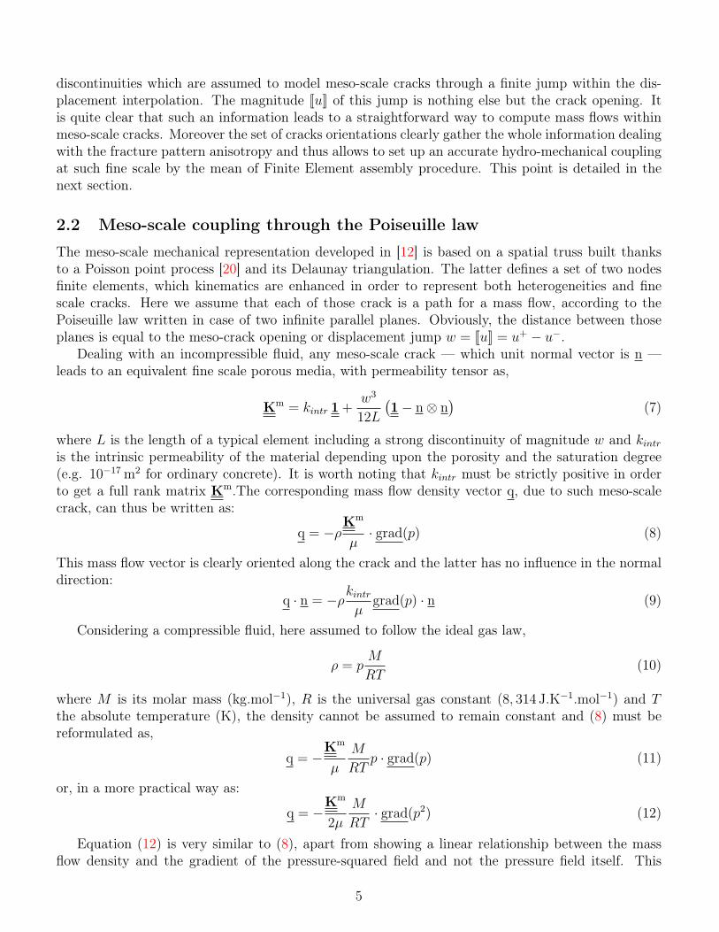
Moreover, we stress here on the influence of the boundary conditions by comparing the two maincases offered by the Hill condition: "uniform pressure" or Dirichlet-type boundary conditions (3) and"uniform mass flow" or Neumann-type boundary conditions (4).
Figure 5: Influence of the boundary conditions : Comparison of Dirichlet and Neumann-type condi-tions
Figure 5 shows that this influence increases as the crack opening is growing as well. This ismainly due to the fact that, considering a single and oriented crack, the domain can be viewed asa Representative Volume Element provided the opening is very small only. When considering largeropenings, the cube is not a RVE anymore, which leads to a major influence of the boundary conditions.In that case, Figure 6 shows that the uniform pressure choice is much more closer to the expectedresult — here the Poiseuille law — than the uniform mass flow one. Hence we choosed for theformer in the subsequent results. This result is in accordance with the postulat formulated by Hillfor mechanical problems [10]. He explains that the Representative Volume Element exists when theratio of the mesoscopic length (length of the sample) over the microscale length (average size of theheterogeneity) "(a) is structurally entirely typical of the whole mixture on average, and (b) containsa sufficient number of inclusions of the apparent overall moduli to be effectively independent of thesurface values of traction and displacement so long as these values are macroscopically uniform". Inour study, as soon as the crack opens, the sample can’t be seen as a RVE as it is "cut" in two parts
11
which is in contradiction with the (a) proposition of Hill. The (b) proposition is also wrong as thereis only one crack, which means one heterogeneity in the sample and therefore not a sufficient numberof inclusions.
Figure 6: Influence of the boundary conditions : Comparison to analytical solution
a) b)
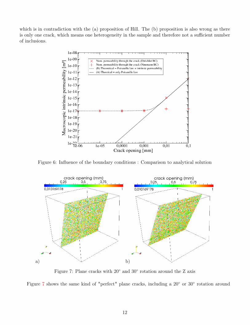
Figure 7: Plane cracks with 20 and 30 rotation around the Z axis
Figure 7 shows the same kind of "perfect" plane cracks, including a 20 or 30 rotation around
12

the Z axis. The corresponding macroscopic permeability tensors are respectively,
KM
([[u]]=10−2mm)=
12.1 26.5 −0.0326.1 75.5 −0.04−0.26 −0.27 87.4
· 10−17m2 (32)
and
KM
([[u]]=10−2mm)=
24.6 38.2 0.0137.6 68.8 −0.010.02 0.02 95.2
· 10−17m2 (33)
The smallest eigenvalue of the matrix (32) is 2.6× 10⁻¹⁷ m2 and 2.84× 10⁻¹⁷ m2 for matrix (33).The corresponding eigenvectors shows a 19.7 angle for the first case and a 30.1 angle for matrix (33),which can be compared to the 20 and 30 angles made by the crack planes. Moreover those valuesare in accordance with the intrinsic permeability of the homogeneous domain and thus shows that thecrack has almost no influence on the mass transfer in the direction perpendicular to its plane. Thelargest two eigenvalues are 85.0 × 10⁻¹⁷ m2 and 87.4 × 10⁻¹⁷ m2 (dealing with matrix (32)) Thosevalues are to be compared to the theoretical permeability corresponding to the Poiseuille law — witha [[u]] = 1.10−2 mm opening — which is 83.3× 10⁻¹⁷ m2.
Finally, we compare the principal components of the macroscopic permeability tensor along thecrack opening, from [[u]] = 10−6 mm to [[u]] = 10−2 mm. Figure (8) shows that the computedtangent permeabilities follow the theoretical cubic law imposed by Poiseuille theory — introduced atthe mesoscale —, while the normal components remains constant and almost equal to the intrinsicpermeability of the surrounding domain.
Figure 8: Evolution of the principal components of the macroscopic permeability tensor along thecrack opening: ’’ stand for the normal direction and ’×’ for the tangent directions
It is also worth noting that the influence of the crack on the mesoscale mass flow and thus on themacroscopic permeability tensor begins with quite small opening (around 1µm).
13

4.2 Permeability of RC element under load
The multiscale framework we present here is suitable for mass transfers within concrete structuresor their components. To that aim we focus on experimental results from [8] who designed a coupledtensile – permeability test on Reinforced Concrete (RC) specimens (610 × 90 × 90 mm3 concreteelement including a 11 mm diameter reinforcement bar). Here we aim at comparing their experimentalmeasures to numerical results and focus on the permeability evaluation along the failure process.
The fine scale mechanical analysis of this RC tie is based on a spatial truss representation [12] builtwith non-adapted meshes. In order to fit to the experimental conditions, displacements are prescribedat both ends of the steel reinforcement bar. Such increasing load leads to progressive cracking of theconcrete element and Figure (9) shows a typical crack pattern obtained from a numerical analysis.Three main macroscale cracks are distributed along the tie which is in accordance with experimentalobservations. Moreover, we show on Figure (9) that there is a quite good agreement between themeasured values of those cracks openings during the loading process and the corresponding numericalvalues.
a) b)
Figure 9: RC tie numerical analysis: a) Numerical crack patterns, b) Maximum crack opening versusload (experimental [8] vs computational results)
On the permeability assessment point of view (here the test deals with water), Figure (10) showsthe norm of the mass flow vector at the end of the failure process. In order to match the experiments,this computation has been made imposing mixed boundary conditions: Dirichlet-type along twoopposite faces of the specimen and Neumann-type (with zero flow rate) for the four other faces.Although the concrete specimen contains a large number of mesoscale cracks, it is clear that the masstransfer takes place within a subset of those cracks, corresponding to several percolated paths. Thus,on the mass transfer point of view, the former may be seen as a set of macroscale cracks. Hence, itis worth noting that, apart from considering the opening value as the pertinent criterion, this masstransfer analysis leads to an other way to determine this set of macroscale cracks. This analysis beinglinear and so quite simple to drive, it is a very convenient way to characterize macroscale cracks.
Finally, Figure (11) shows the permeability coefficient – here in [m.s−1] in order to match with theexperimental results – evolution along the load increase. The permeability increases from approxi-matively 2.10−10m.s−1 to 1.10−5m.s−1 both for numerical and experimental studies. It is also worthnoting that the increasing rate is also quite well represented. Yet, the permeability rise appears forsmaller loading values in the numerical study than in the experimental one. Considering the concrete
14

Figure 10: RC tie numerical analysis: Numerical values of the mass flow vector norm
Figure 11: RC tie numerical analysis: Water permeability coefficient versus load [8] vs numericalresults
heterogeneity as well as the experimental discrepancy, those results are quite promising.
15

5 Conclusions and outlooks
In this work we have discussed the use of a sequential two-scales (meso–macro) numerical strategyin order to upscale the permeability of fractured media such as concrete. Sequential multi-scalesmethods aim at building macroscopic models from a sequence of lower scale computations and requireboth a macroscale model — here porous media flow — and a fine scale numerical analysis. Suchsimple upscaling processes made sequential multi-scale methods quite popular in order to computemacroscopic properties of heterogeneous media.
Here the cornerstone relies in the coupling of strong discontinuities — which are supposed to modelfine scale fractures within the FE mechanical model — to the fine scale permeability tensor throughPoiseuille law. Such coupling is made possible thanks to the strong discontinuity approach whichprovides the opening value for each of these cracks. Indeed, at such meso level — which we assume torepresent heterogeneities from 1 mm — each crack is a path for an oriented flow and, except for lowstress levels, the upscaling process is not possible to manage on a analytical basis. We have presenteddifferent numerical tests showing the ability of the numerical upscaling process to model anisotropicmacroscopic permeability tensor which confirm the intuitive idea that the whole set of fine crackscannot lead to an isotropic permeability tensor.
Furthermore, we have compared some experimental results obtained on Reinforced Concrete ele-ments by [8]. Here the heterogeneities are the reinforcement bars and we compute both the mass flowvector and the resultant macroscopic permeability. When compared to the experiments the two-scalesnumerical analysis shows a good agreement. However, we can observe a high discrepancy within theexperimental data. Consequently, further tests dealing with components of RC structures are neededbefore a complete assessment may be reached.
Finally, it is worth noting that any upscaling process of the permeability may be viewed as anadvantageous tool in order to define whether the fracture pattern is percolated (or connected) or not.Actually such feature comes as a by-product results of the two-scales analysis. Hence, to the authorspoint of view, important efforts should be paid in the near future in order to develop those multi-scalestrategies, rather within an integrated framework.
References
[1] Choinska M. Effets de la température, du chargement mécanique et de leurs interactions surla perméabilité du béton de structure. PhD Thesis, Ecole Centrale de Nantes & Université deNantes 2006.
[2] Picandet V, Khelidj A, Bellegou H. Crack effects on gas and water permeability of concretes.Cement and Concrete Research 2009; 39:537–547. doi=10.1016/j.cemconres.2009.03.009.
[3] Pijaudier-Cabot G, Dufour F, Choinska M. Permeability due to the increase of damage in con-crete : From diffuse to localized damage distributions. Journal of Engineering Mechanics 2009;135:1022–1028. doi=10.1061/(ASCE)EM.1943-7889.0000016.
[4] Shao J, Zhou H, Chau K. Coupling between anisotropic damage and permeability variation inbrittle rocks. International Journal for Numerical and Analytical Methods in Geomechanics 2005;29:1231–1247. doi=10.1002/nag.457.
16

[5] Chatzigeorgiou G, Picandet V, Khelidj A, Pijaudier-Cabot G. Coupling between progressivedamage and permeability of concrete: analysis with a discrete model. Int. J. Numer. Anal.Meth. Geomech. 2005; 29:1005–1018. doi=10.1002/nag.445.
[6] Dormieux L, Kondo D. Approche micromécanique du couplage perméabilité – endommagement.C. R. Mecanique 2004; 332:135–140. doi=10.1016/j.crme.2003.11.003.
[7] Feyel F, Chaboche JL. Multi-scale non-linear FE2 analysis of composite structures: damage andfiber size effects. Revue européenne des Éléments Finis: NUMDAM’00 issue 2001; 10:449–472.
[8] Desmettre C, Charron J. Novel water permeability device for reinforced concrete under load.Mat. and Struct. 2011; doi=10.1617/s11527-011-9729-6.
[9] Bear J. Dynamics of Fluids in Porous Media. Dover Publications, 1972.
[10] Hill R. Elastic properties of reinforced solids: some theoretical principles. J. Mech. Phys. Solids1963; 11:357–372. doi=10.1016/0022-5096(63)90036-X.
[11] Du X, Ostaja-Starzewski M. On the size of representative volume element for darcy law in randommedia. Proc. R. Soc. 2006; 462:2949–2963. doi=10.1098/rspa.2006.1704.
[12] Benkemoun N, Hautefeuille M, Colliat JB, Ibrahimbegovic A. Failure of heterogeneous materi-als: 3d meso-scale fe models with embedded discontinuities. International Journal of NumericalMethods in Engineering 2010; 82:1671–1688. doi=10.1002/nme.2816.
[13] Moës N, Cloirec M, Cartraud P, Remacle JF. A computational approach to handle complexmicrostructure geometries. Computer Methods in Applied Mechanics and Engineering 2003;192:3163–3177. doi=10.1016/S0045-7825(03)00346-3.
[14] Hillerborg A. Application of the fictious crack model to different types of materials. InternationalJournal of Fracture 1991; 51:95–102. doi=10.1007/BF00033972.
[15] Pijaudier-Cabot G, Bažant ZP. Nonlocal damage theory. Journal of Engineering Mechanics(ASCE) 1987; 113:1512–1533. doi=10.1061/(ASCE)0733-9399.
[16] Wells GN, Sluys LJ. Application of embedded discontinuities for softening solids. EngineeringFracture Mechanics 2000; 65:263–281. doi=10.1016/S0013-7944(99)00120-4.
[17] Brancherie D, Ibrahimbegovic A. Novel isotropic continuum-discrete damage model capable ofrepresenting localized failure of massive structures. Part I: theoretical formulation and numericalimplementation. Engineering Computation 2009; 26:100–127. doi=10.1108/02644400910924825.
[18] Moës N, Dolbow J, Belytschko T. A finite element method for crack growth withoutremeshing. International Journal for Numerical Methods in Engineering 1999; 46:131–150.doi=10.1002/(SICI)1097-0207(19990910)46:1.
[19] Benkemoun N, Ibrahimbegovic A, Colliat JB. Anisotropic constitutive model of plasticity capableof accounting for details of meso-structure of two-phase composite material. Computers andStructures 2012; 90-91:153–162. doi=10.1016/j.compstruc.2011.09.003.
[20] Cox D, Isham V. Point Processes. Chapman & Hall, 1980.
17

[21] Brezzi F, Fortin M. Mixed and hybrid finite element methods. Springer-Verlag, 1991.
[22] Kassiotis C, Hautefeuille M. coFeap’s Manual 2008. http://www.lmt.ens-cachan.fr/cofeap/files/cofeap_manual.pdf.
[23] Schewchuk JR. An introduction to the conjugate gradient method without the agonizing pain.Technical Report, School of computer science, Carnagie Mellon University, Pittsburgh, PA 152131994. http://www.cs.cmu.edu/~quake-papers/painless-conjugate-gradient.pdf.
18