unveiling the physiochemical aspects of the matrix in
TRANSCRIPT
© 2021 The Author(s). Published by the Royal Society of Chemistry Mater. Adv., 2021, 2, 4165–4189 | 4165
Cite this: Mater. Adv., 2021,
2, 4165
Unveiling the physiochemical aspects ofthe matrix in improving sulfur-loading forroom-temperature sodium–sulfur batteries
Sungjemmenla, Chhail Bihari Soni, S. K. Vineeth and Vipin Kumar *
The sulfur cathode in Na/S batteries possesses a very high theoretical specific capacity of about
1675 mA h g�1 and specific energy of 1230 W h kg�1 (which is over five times that of the LiCoO2
cathode in Li-ion batteries), besides high abundance and cost-effectiveness of the electrode materials.
The sulfur cathode in Na/S batteries undergoes various electrochemical processes, where a series of
soluble sodium polysulfides are formed during the discharge reaction, which adversely affects the
operation of the cell. Furthermore, the viable application of RT-Na/S batteries is severely challenged by
various obstacles, including their short-life and low-sulfur utilization, which become more serious when
sulfur loading is increased to the practically acceptable level of over 5 mg cm�2. Thus, there have been
innovative efforts in recent years to manipulate the physiochemistry of the matrix to overcome these
barriers toward the practical application of RT-Na/S batteries with an improved sulfur loading close to
practical limits. The rational design of the matrix (i.e., physicochemical aspects) with a high-sulfur
utilization and long lifespan are two crucial challenges that Na/S batteries are experiencing currently and
require immediate attention to be addressed. This review highlights the recent progress on tuning
the physiochemistry of the matrix through chemical and physical means to realize an improved
sulfur-loading. Particularly, basic insight into the chemical binding, strategies for mesoscale assembly,
unique architectures, and configurational innovation in the cathode are the specific focus. Finally, novel
strategies to improve sulfur-loading are proposed to guide the future development of high-sulfur
loading RT-Na/S batteries.
1. Introduction
There is growing interest in high-energy rechargeable batteriesfor large-scale stationary energy storage.1–3 Rechargeable lithium-ion batteries with an energy density of about 180 W h kg�1 arestill the first choice for portable and mobile applications, but thehigh cost of Li-ion batteries per kWh limits their use in stationarystorage applications.3–8 Besides, the performance of Li-ionbatteries has plateaued due to the fundamental limitations ofthe electrode materials.
Recently, interest in sodium–sulfur batteries has been reviveddue to their unique attributes, including high theoretical specificcapacity and energy density, high natural abundance and long-term sustainability.9 In addition, sodium–sulfur electrochemistryoffers several other advantages, such as (1) stable-operation,(2) minimal self-discharge, (3) low-cost per cycle, (4) high energyefficiency, and (5) non-toxicity.10 Significant progress has been madein high-temperature sodium–sulfur (HT-Na/S) battery technology
owing to its high theoretical energy density (760 W h kg�1) andpower capability with excellent durability for over 15 years or2500 cycles.11 HT-Na/S batteries as cutting-edge technology havefound applications in space, electric vehicles grid storage, andaeronautics.12,13 Attempts have been made to utilize HT-Na/Sbatteries for large-scale grid storage applications. For instance,Kawakami and coworkers stabilized the fluctuating wind powerof about 51 MW using a 34 MW HT-Na/S battery systemin Japan.14 Similarly, other groups used HT-Na/S batteries forload-leveling in wind-farms.15 HT-Na/S battery technology hasmatured over time and been well constructed and developedmainly for large-scale storage applications. However, despitethese achievements, HT-Na/S is severely compromised regardingsafety due to its high operating temperatures (4300 1C), whichare required to achieve the desired ionic conductivity of the solid–electrolyte. In addition, the reaction between molten sulfur andsodium can liberate a high enthalpy of about�420 kJ mol�1, whichmay further contribute to an increase in the cell temperature.16
Thus, the high operating temperature (300–350 1C), high initial cost,corrosivity and low Coulombic efficiency of HT-Na/S batterieschallenge their long-term viability.
Centre for Energy Studies (CES), Indian Institute of Technology Delhi, Hauz Khas,
New Delhi, Delhi, 110016, India. E-mail: [email protected]
Received 23rd March 2021,Accepted 24th May 2021
DOI: 10.1039/d1ma00247c
rsc.li/materials-advances
MaterialsAdvances
REVIEW
Ope
n A
cces
s A
rtic
le. P
ublis
hed
on 1
4 Ju
ne 2
021.
Dow
nloa
ded
on 2
/28/
2022
8:4
3:24
AM
. T
his
artic
le is
lice
nsed
und
er a
Cre
ativ
e C
omm
ons
Attr
ibut
ion
3.0
Unp
orte
d L
icen
ce.
View Article OnlineView Journal | View Issue

4166 | Mater. Adv., 2021, 2, 4165–4189 © 2021 The Author(s). Published by the Royal Society of Chemistry
In contrast to the HT-Na/S battery, the room-temperaturesodium–sulfur (RT-Na/S) battery offers a safe and reliable operationwith a low operating cost,17–19 delivering a remarkably hightheoretical specific energy of B1230 W h kg�1.20 Park andco-workers proposed the idea of developing a room-temperatureanalogue instead, which consists of a solid form of both sodiumand sulfur electrodes.21 This battery delivered an initial dischargecapacity of about 489 mA h g�1; however, it could only be cycled for20 cycles with a drastic decrease (nearly tenfold) in its reversiblecapacity. Wang et al.22 investigated for the first time the use of aconductive polymer-PAN/S as the cathode material for RT-Na/S toenhance both the cycling stability and performance of the cell.The hybrid composite sulfur cathode exhibited an improvedperformance of about 655 mA h g�1; however, the cell wasplagued with a low cycle-life (only for 18 cycles), while it retaineda reversible capacity of about 500 mA h g�1. Subsequently,significant progress has been made in the development ofstate-of-the-art composite cathodes with remarkable progressin the rate capability and ultra-long cycle-life.23,24 Recently,attempts have been made to understand the charging/dischargingmechanism in Na/S batteries via both experiment and theoreticalmodeling. Although the intermediate reactions are very complex,the generally accepted discharging reaction in the RT-Na/S batteryfollows S8 - Na2S8 - Na2S6 - Na2S4 - Na2S2 - Na2S, wherethe long-chain polysulfides, i.e., Na2S8 and Na2S6, readily dissolvein the electrolyte.25 In most cases, the dissolved polysulfides movetowards the anode (i.e., shutting effect) and hamper the anodeoperation permanently, leading to rapid capacity fading and poorcycling stability.26,27 Polysulfide cross-over or shuttling can beevaded partly through physical or chemical trapping by the matrix,i.e., carbon scaffold, in most cases.28 Extensive research effortshave been focused on finding better matrix materials that canoffer great absorption sites for the long-chain polysulfides tobind without compromising with electronic conductivity ofthe electrode materials. However, the key challenge with thistechnology is the low sulfur loading, which lowers its capacityand the overall specific energy.
Although good progress in the electrochemistry of cathodecomposites has been achieved in recent years, the low sulfur
loading, which is below 3 mg cm�2, eventually hinders the cellfrom reaching its unprecedented theoretical value. Further-more, when attempts were made to improve the sulfur loadingin the cathode, the performance of the cell was observed todeteriorate rapidly due to the lack of efficient binding sites,strong inter-particle interaction, and optimized ratio of electro-lyte and sulfur (i.e., E/S).29 Thus, to achieve a high specificenergy, it is urgent to increase the loading (43 mg cm�2) andweight percentage of sulfur.30 Pope et al. reported differentcathode architectures for Li/S batteries, where they analyzed thespecific energy as a function of the sulfur loading.31 Theyidentified that a higher specific energy of about 400 W h kg�1
could be achieved with sulfur loadings greater than 2 mg cm�2.It is evident that an increase in the sulfur loading has a profoundimpact on the practicality of metal–sulfur battery systems. Severalresearch groups have presented impactful reviews on the Na–Sbattery;32–35 however, this mini-review introduces the key issuesand different aspects of the matrix towards the development of ahigh loading sulfur cathode for RT-Na/S batteries. Particularly,the recent advances with a judicious combination of differentcomposite materials and representative physical and chemicalaspects of cathode engineering are summarized, as schematicallydepicted in Fig. 1. In addition, novel strategies to improve thesulfur loading are proposed to guide the future development ofhigh-sulfur-loading sulfur cathodes for RT-Na/S batteries.
2. The physio-chemistry of the matrixfor sulfur cathodes
A room-temperature Na–S battery is comprised of a sulfurcathode, sodium metal anode, and a separator soaked in aliquid electrolyte, as depicted schematically in Fig. 2. The sulfurcathode, which consists of elemental sulfur particles, binder,and conductive filler, undergoes severe chemical and structuralchanges during the charge/discharge reactions. The chemicaland physical changes that occur in the matrix mainly dictatethe stability of the sulfur cathode and kinetics of the conversionreactions. Although the charge/discharge reactions are very
Fig. 1 Schematic illustration of the rational design of the matrix for high-loading sulfur cathodes for RT/Na–S batteries.
Review Materials Advances
Ope
n A
cces
s A
rtic
le. P
ublis
hed
on 1
4 Ju
ne 2
021.
Dow
nloa
ded
on 2
/28/
2022
8:4
3:24
AM
. T
his
artic
le is
lice
nsed
und
er a
Cre
ativ
e C
omm
ons
Attr
ibut
ion
3.0
Unp
orte
d L
icen
ce.
View Article Online

© 2021 The Author(s). Published by the Royal Society of Chemistry Mater. Adv., 2021, 2, 4165–4189 | 4167
complicated, the intermediate reaction steps that occur duringthe reactions are presented below through a series of reactions(eqn (1)–(4)).34,36
S8 + 2Na+ + 2e� - Na2S8 (solid–liquid transition;
B2.20 V vs. Na/Na+) (1)
Na2S8 + 2Na+ + 2e� - 2Na2S4 (liquid–liquid transition;
2.20–1.65 V vs. Na/Na+) (2)
Na2S4 þ2
3Naþ þ 2
3e� ! 4
3Na2S3
liquid�solid transition; � 1:65 V vs: Na=Naþð Þ
Na2S4 þ 2Naþ þ 2e� ! 2Na2S2
Na2S4 þ 6Naþ þ 6e� ! 4Na2S
(3)
Na2S2 + 2Na+ +2e� - 2Na2S (solid–solid transition;
1.65–1.20 V vs. Na/Na+) (4)
The overall reaction during the discharge process can beexpressed as:
Anode: 2Na - 2Na+ + 2e�
Cathode: 1/8S8 + 2Na+ +2e� - Na2S
The reduction of Na+ ions occurs at the cathode, where sulfurgains electrons and combines with the sodium ions to producea range of polysulfides (Na2Sn), ranging from long-chain (4 rn r 8) to short-chain polysulfides (1 r n r 4).36 The dissolutionand diffusion of sodium polysulfides upon the oxidation ofNa2Sx (x = 1) provide mediators for the redox reactions toenhance the insulating nature of the elemental sulfur (5 �10�30 S cm�1@25 1C) and Na2S.35,37 Due to the high solubilityof the reaction intermediates, they shuttle between the anodeand cathode, leading to polysulfide shuttling. The shuttle effectfor RT-Na/S is even more severe than that of the Li–S battery,and consequently large volume fluctuations (about 170%) occur,leading to the structural collapse of the cathode during repeated
charge/discharge cycles.38–41 The aforementioned issues primarilyrestrict the proper utilization of sulfur materials and mainlycontribute to the low specific energy of RT-Na/S.42 With an increasein the sulfur loading, the performance of the battery deteriorateseven faster due to the limited diffusion of sodium ions and lowaccessibility of the electrolyte. All these factors severely affect thebattery performance (including low Coulombic efficiency, self-discharge, loss of sulfur and its dissociated products, and fastfading rate41) and hamper the further development of RT-Na/Sbatteries. Therefore, the rational design of the matrix materials,which can overcome the aforementioned issues, is crucial torealize the practical use of RT-Na/S batteries.
2.1 Chemical aspects
The sulfur cathode contributes two electrons to the reactionand offers a high theoretical capacity of about 1675 mA h g�1.43
However, it is immensely challenging to extract the theoreticalcapacity from sulfur cathode due to two major challenges. Firstly,the dissolution of high-order polysulfide intermediates (Na2S8–Na2S4, i.e., long-chain polysulfides) in organic electrolytes causessevere sulfur loss in the cathode, reducing the cycle-life of RT-Na/S.The dissolution of the high-order polysulfides also requires aflooded electrolyte (FE) to achieve a high power density, sacrificingthe total energy density. Secondly, Na plating/stripping continuouslyconsumes the Na-metal anode and electrolyte during cycling, whichrequires excess Na-metal and electrolyte, thus further reducing theCoulombic efficiency and energy density of RT-Na/S.
To date, numerous strategies and different material chemistrieshave been developed to modify the matrix (i.e., sulfur host) andminimize dissolution of sodium polysulfides. To promote thekinetics of the conversion reactions, a chemically modified sulfurmatrix has been demonstrated as a potential solution to enhancethe performance of RT-Na/S batteries.
2.1.1 Chemical binding. The poor ionic and electronicconductivity of the elemental sulfur cathode can be greatly improvedthrough chemical modification of the sulfur matrix. The approachthat has been investigated for improving the electronic conductivityis based on the coating technique,44,45 which mainly involvescoating a thin polymeric material to promote the inter-particlecontact and chemical trapping of the dissolved intermediatesodium polysulfides.46,47 Attempts have been made to designand develop various matrices with diverse chemical structures andmorphologies,48 which have significantly improved the stability ofthe sulfur cathode during the charge/discharge reactions. However,the chemically modified structure could not prevent capacity fadingduring cycling, which may likely be due to the weak interparticlechemical interaction within the electrode materials. It is noteworthythat the chemical coating alters the chemical structure of the matrix,but most polymer coatings examined to date do not establish goodchemical interaction with the sulfur particles. Given that the weakinteractions can be easily broken upon high-volume changes duringcycling, it is nearly impossible to prohibit capacity fading using thechemically modified matrix approach.49–51
The other aspect that can be employed is to use binders toalter the chemical functionality of the matrix instead of polymericcoatings. The chemically altered binder approach greatly improves
Fig. 2 Schematic representation of an RT-Na/S battery.
Materials Advances Review
Ope
n A
cces
s A
rtic
le. P
ublis
hed
on 1
4 Ju
ne 2
021.
Dow
nloa
ded
on 2
/28/
2022
8:4
3:24
AM
. T
his
artic
le is
lice
nsed
und
er a
Cre
ativ
e C
omm
ons
Attr
ibut
ion
3.0
Unp
orte
d L
icen
ce.
View Article Online

4168 | Mater. Adv., 2021, 2, 4165–4189 © 2021 The Author(s). Published by the Royal Society of Chemistry
the structural integrity of the cathode.52–54 Although the binderaccounts for only about 2 to 10 wt% of the overall electrodematerial, it plays a critical role in ensuring the stable performanceof batteries. The primary function of a chemical binder is toprovide (i) strong inter-particle adhesion and binding, (ii) abun-dant adsorption sites to adsorb or absorb the discharge products,and (iii) a robust and interconnected structure to prevent pulver-ization of the cathode material during volumetric contraction/expansion during the charge/discharge reactions.55–57 Tradition-ally, linear binders, such as poly(vinylidene-fluoride) (PVDF), havebeen used to form cathode films for RT-Na/S batteries. The polargroups (i.e., –CF2) of the PVDF binder molecules facilitate theadhesion among various components of the cathode, whichinclude sulfur particles, conductive fillers, and the current collector.In addition, the van der Waals forces among the polymer chainsprovide good elasticity to accommodate the volume change uponrepeated discharge/charge cycles. It is important to note that thevolume change in the sulfur cathode is many times that of theconventional oxide cathode,40,58 and thus the PVDF binder encoun-ters a significant challenge in ensuring long-term stability of thecathode, especially when the sulfur loading is high or close to thepractical limits. Accordingly, by altering the molecular structure andsurface chemistry of the binder molecules, researchers can explorealternative binders to promote better mechanical properties.59,60
Polar functional groups, for instance, –OH, and –COOH, have beenincorporated to form covalent bonds with S–C composites and thesubstrate. Recently, Alex and co-workers tailored the binder inter-actions with the cathode materials through –COOH functionalgroups to gain a better perspective towards binder assembly.54
Carboxyl-containing binders were utilized as an alternative to the
traditional PVDF binder due to the relatively stronger interaction oftheir polar groups with sodium polysulfide. Polyacrylic acid (PAA)binder, which behaves as a trap for the soluble sodium polysulfidesduring the sodiation cycles, can readily adsorb sodium polysulfide.The adsorption of sodium polysulfide was validated throughtheoretical calculations. For example, the binding energy ofNa2S for PAA binder is about 2.02 eV, which is nearly 60% thatof the PVDF binder (binding energy of about 1.20 eV). Scanningelectron microscopy (SEM) images revealed the uniform parti-cle distribution on the cathode surface for a PAA-based sulfurcathode, whereas the PVDF-based cathode contained largefractures and showed lower contrast due to the passivationlayer on its surface (see Fig. 3a–d). As schematically illustratedin Fig. 3e, a conjugated pyridine-like backbone confirms thecyclization in forming strong interactions between CQC andCQN bonds. The strong bonds formed with the carboxylgroups potentially act as a chemical trap if discharge productsare inadvertently formed during sodiation. Consequently, dueto these strong interactions, a sulfur content as high as 41 wt%could be achieved and the mass loading of the active materialcould reach about 1.8 mg cm�2. Due to the locally modifiedmatrix structure, the rate capability tests showed high specificcapacity values for the PAA-based cathodes of 1023 mA h g�1,920 mA h g�1 and 800 mA h g�1 at 1C, 2C and 4C, respectively.In contrast, the PVDF based cathode exhibited a much lowerspecific capacity of 554 mA h g�1 at a C-rate of 4C.
Besides PAA, a hybrid sodium alginate–polyaniline matrixbinder was also developed and observed to play a crucial role dueto its inherent stiffness and swelling properties.61 In contrast to theconventional binder (see Fig. 3f), sodium alginate could preserve
Fig. 3 SEM images of (a and c) PVDF cathode and (b and d) PAA cathode at different magnifications. (e) Schematic illustration of the sulfur bondingmodes in S-PAN with the corresponding sodiation/de-sodiation reaction. Reproduced with permission.54 Copyright 2020, The Royal Society ofChemistry. (f and g) Schematic of the proposed role of the conventional and polysaccharide binder to counteract the volume expansion of sulfur duringsodium-ion insertion. Reproduced with permission.61 Copyright 2019, the American Chemical Society.
Review Materials Advances
Ope
n A
cces
s A
rtic
le. P
ublis
hed
on 1
4 Ju
ne 2
021.
Dow
nloa
ded
on 2
/28/
2022
8:4
3:24
AM
. T
his
artic
le is
lice
nsed
und
er a
Cre
ativ
e C
omm
ons
Attr
ibut
ion
3.0
Unp
orte
d L
icen
ce.
View Article Online
© 2021 The Author(s). Published by the Royal Society of Chemistry Mater. Adv., 2021, 2, 4165–4189 | 4169
the structural integrity of the sulfur cathode during the sodiuminsertion and extraction process, as shown in Fig. 3g. In addition,the hybrid binder of sodium alginate–polyaniline could serve as aconductive matrix to facilitate the movement of ions and electronsand ensured a sulfur loading of about 2.05 mg cm�2.
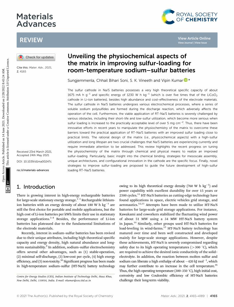
Another broad approach of covalent fixing can reinforce thestrong chemical binding interactions between the sulfur chainsand the host molecules. Consequently, Arnab et al.30 reported asulfur-embedded polymer matrix as the host for the cathodematerial for RT-Na/S batteries with a high sulfur loading ofabout 90 wt%. The sulfur co-polymer was obtained via a thermalring-opening polymerization strategy using cardonol-based benzox-azine as the co-monomer (CS-90) (see Fig. 4a), which was thenincorporated with reduced graphene oxide (CS-90/rGO). Besides thehigh reactivity of the co-monomer, the presence of multiple activesites prompted the co-monomer to anchor the polysulfane chains,resulting in an average S-loading of about 2.14 mg cm�2. The high
binding effect of the covalently bonded active sulfur with theorganic moiety units alleviated the dissolution effect of the sulfurspecies during cycling. However, the cathode delivered a capacityof 285 mA h g�1 after 100 cycles at a current density of 0.6C.
Similarly, Wu and co-workers proposed a covalently bonded sulfur–carbon composite with benzenedisulfonic acid (SC-BDSA) with–SO3H and SO4
� as the sulfur source in an RT-Na/S battery system,which ensured an active mass loading of B3 mg cm�2.62 Fig. 4bschematically illustrates (1) a short-chain sulfur–carbon compositewith a sulfur content of 8.53 wt%, (2) replacing benzenesulfonicacid with di-substituted benzenedisulfonic acid (BDSA) with anincreased sulfur content of 18.33 wt% and (3) replacing the salttemplate with potassium sulfate, resulting in a high S-content of40.07 wt%. Due to the O–S/C–S bridge bonds present in the sulfurspecies, high conductivity can be maintained to provide excellentinterfacial contact among the particles in SC-BDSA. Consequently,the RS2O2
� units formed on the surface of the complex matrix canact as an internal mediator to strongly bind the long-chain sodiumpolysulfides in the electrolyte. This results in catenating polythio-nates, which trigger their conversion to short-chain sodium poly-sulfides, as depicted in the following reaction.
The cell exhibited high cyclic stability of 1000 cycles with aminimal decay rate of 0.035% per cycle with a reversiblecapacity of 452 mA h g�1 at 2500 mA g�1 and an initialdischarge capacity of 696 mA h g�1.
Fig. 4 (a) Chemical structure of copolymer by reaction of Ca monomer with sulfur. Reproduced with permission.30 Copyright 2017, the AmericanChemical Society. (b) Schematic representation of the synthetic processes of C-BSA, C-BDSA, and SC-BDSA. Reproduced with permission.62 Copyright2019, John Wiley and Sons. (c) Schematic illustration of the synthesis of SC. Reproduced with permission.63 Copyright 2019, The Royal Society ofChemistry. (d) Synthetic route of a covalent sulfur–carbon composite via the solvothermal strategy. Reproduced with permission.64 Copyright 2020, theAmerican Chemical Society.
Materials Advances Review
Ope
n A
cces
s A
rtic
le. P
ublis
hed
on 1
4 Ju
ne 2
021.
Dow
nloa
ded
on 2
/28/
2022
8:4
3:24
AM
. T
his
artic
le is
lice
nsed
und
er a
Cre
ativ
e C
omm
ons
Attr
ibut
ion
3.0
Unp
orte
d L
icen
ce.
View Article Online

4170 | Mater. Adv., 2021, 2, 4165–4189 © 2021 The Author(s). Published by the Royal Society of Chemistry
Considering the covalent binding effect with sulfur, anothergroup demonstrated the idea of confinement to boost the bindingof sulfur with the matrix. Sulfur atoms were confined to a carbonmatrix, which was named ‘‘thioether bond-functionalized carbon(SC)’’.63 This can be an effective approach to mitigate the dissolu-tion effect of soluble polysulfides. They investigated if the devel-opment of sulfur atoms bonded to carbon species can protect thesystem from reduced sulfur species of long chain-polysulfidesowing to the generation of soluble sulfur species (S2� and S2
2�)in the routine carbonate electrolyte. SC, containing a thioetherbond, can be untied through voltage scissors in the voltage rangeof 0.01–0.5 V vs. Na/Na+ and the cell can deliver a large reversiblecapacity for sodium storage. The insoluble reduced sodium specieswere then incorporated in the carbon defects induced by thecleaved sulfur (see Fig. 4c), overcoming the detrimental trans-formation to long-chain polysulfides. However, despite theireffort to suppress the shuttle effect, the active material loadingobtained was very low at 0.9–1.1 mg cm�2. Recently, Li et al.64
studied the in situ preparation of covalent configured carbonsulfur through the wet-chemical solvothermal strategy usingcarbon disulfide as the precursor in the presence of red phos-phorus. S–C bonds were formed with the uniform distributionof sulfur on the periphery and interior of the carbon skeleton, asdepicted in Fig. 4d. The ease of access of sodium ions betweenthe carbon interlayer could activate the sulfur species electro-chemically under 0.5 V. They claimed that the enlarged inter-layer spacing of B0.4 nm allowed the free transportation ofsodium ions into the matrix, which reacted with sulfur, allowingit to behave as a capacity donor in the subsequent cycles.The covalent cathode composite maintained a high reversiblecapacity of 811.4 mA h g�1 after 950 ultra-long cycles at 1.6C.Additionally, the covalent-S–C electrode delivered a remarkablecapacity of 700 mA h g�1 at 8.1C.
2.1.2 Dopants. Besides the exceptional effect of chemicalbinding on the battery performance, most of the binders areelectrochemically inactive and add to the dead weight of thecell and increase the thickness of the materials, and hence thecharge-transfer resistance. Therefore, to tune the interactionbetween sulfur particles and the matrix, other strategies, suchas elemental doping of the matrix, have been examined inrecently and identified to be highly effective. Due to the multi-functional aspects of elemental doping, i.e., enhanced sulfurloading, improved conversion kinetics and good electronicconductivity of the matrix, various elemental dopants, such asN, B, and P have been examined.65–69
Recently, Zhang et al.70 developed an elemental cobalt (i.e.,atomic cobalt)-doped hollow carbon nanosphere matrix for thesulfur cathode, and reported an improved sulfur loading ofabout 5 mg cm�2. Due to the strong polar interaction betweenthe Co and S atoms, the matrix could accommodate a highloading of sulfur with improved kinetics in the conversionreactions. Theoretical calculations were performed to under-stand the kinetically fast reaction of Na2S with the Co-dopedmatrix, as shown in Fig. 5a and b. The strong binding with thedoped matrix allows a complete sodiation reaction, which effectivelyalleviates the shuttle effect and improves the cycling stability.
The matrix doped with Co-atoms allows the facile adsorption ofsodium polysulfides due to the relatively low or negative energybarrier for the adsorption reaction, as shown in Fig. 5c. Thus,this enabled stability for over 600 cycles at a current density of100 mA g�1. The matrix without Co dopant could deliver aninitial reversible of 1209 mA h g�1 with a rapid decay in the capacityof 271 mA h g�1 after 600 cycles. Significantly, the addition of cobaltclusters within the matrix enhanced the utilization of sulfur, wherethe sodium polysulfides confined within the shell of carbon couldbe catalytically reduced to Na2S. This attenuated the dissolution ofpolysulfides based on the polar–polar interactions, as illustrated inFig. 5d and e.
Zheng et al. studied ‘‘a highly feasible nano-copper-assistedimmobilizing sulfur in high-surface-area mesoporous carbon(HSMC)’’ prepared via the multiple wetness impregnation andsynchro-dry method with a S-content of 50 wt%.73 In additionto the physical encapsulation of sulfur in the mesoporouscarbon, sulfur was also chemically stabilized with the coppernanoparticles, resulting in enhanced conductivity in the compositecathode. The HSMC–Cu–S cathode delivered a high dischargecapacity of about 610 mA h g�1 at 0.03C after 110 cycles with ahigh Coulombic efficiency of about 100%. Despite the high initialdischarge capacity of B1000 mA h g�1 and improved kineticsoffered by the inclusion of the copper cluster in the matrix, thefeasibility of the system was hindered due to its low sulfur loading(B1 mg cm�2 with 50 wt% S-content). Similarly, Zhu et al.74
modified the carbon matrix with 0.14 at% iron atoms and nitrogento develop a hybrid sulfur cathode. The nitrogen-doped carbonnanospheres can expedite the transport of ions and electrons,whereas the iron atoms serve as catalytic sites for strongerchemical interaction and conversion for the discharge productsof sulfur. The hybrid cathode could deliver a reversible capacity of359 mA h g�1 and 180 mA h g�1 at a current density of 0.1 A g�1
and 1 A g�1, respectively, with a high coulombic efficiency of about100% after 200 cycles. Recently, Wang et al. introduced ‘‘aneffective sulfiphilic matrix,’’ i.e., gold nanodot-decorated hierarch-ical N-doped carbon microspheres (CN/Au/S).71 Due to the highaffinity of CN/Au towards sulfur atoms, a high sulfur content ofabout 56.5 wt% could be achieved. The matrix doped with goldnanodots (i.e., CN/Au/S) exhibited a higher binding energy forsulfur atoms compared to the matrix without dopant, indicatingthe strong interaction between the sulfur particles and goldnanodots, consequently trapping the sodium polysulfides dur-ing the cycling process. Apparently, the high binding energies ofthe elemental sulfur and sodium polysulfides upon the additionof gold clusters demonstrate their effectiveness in achieving ahigher sulfur loading. The presence of gold nanodots enhancedthe adsorption between the matrix and polysulfides (Na2Sn; 4 rn r 1), which helped alleviate the shuttle effect to a great extent.The as-modified matrix in the sulfur cathode exhibited long-term cycling stability, retaining a capacity of about 430 mA h g�1
after 1000 cycles, and a reversible capacity of about 369 mA h g�1
after 2000 cycles at a current density of 2 A g�1 and 10 A g�1,respectively. This is attributed to the fact that sulfur and itsdischarged species show higher absorption energies over CN/Aucompared to the matrix without gold nanodots, as shown in Fig. 5f.
Review Materials Advances
Ope
n A
cces
s A
rtic
le. P
ublis
hed
on 1
4 Ju
ne 2
021.
Dow
nloa
ded
on 2
/28/
2022
8:4
3:24
AM
. T
his
artic
le is
lice
nsed
und
er a
Cre
ativ
e C
omm
ons
Attr
ibut
ion
3.0
Unp
orte
d L
icen
ce.
View Article Online

© 2021 The Author(s). Published by the Royal Society of Chemistry Mater. Adv., 2021, 2, 4165–4189 | 4171
In addition, the lower Gibbs free energy change for the golddoped matrix suggests the spontaneity of the reaction, resultingin enhanced adsorption capability, which efficiently mitigatesthe polysulfides shuttling, as shown in Fig. 5g.
Intrigued by the effect of elemental doping, Li et al.72 alteredthe SPAN matrix with tellurium atoms to form a sulfur cathodefor RT-Na/S. The reaction kinetics were greatly improved with ahigh sulfur content of about 47.77 wt% of the active material.The tellurium-doped SPAN enhanced the reversible kinetics ofthe system (see Fig. 5h) with improved reversibility. Besidesthe fast reaction kinetics and the high electrochemical perfor-mance of Te0.04S0.96@pPAN, a high sodium ion diffusion coeffi-cient and a higher electronic conductivity of at least 1.6 timesthat of pPAN@S could be achieved with Te0.04S0.96@pPAN. Thecycle-life of over 600 cycles was attained with the Te0.04S0.96@pPAN cathode, retaining a discharge capacity of about970 mA h g�1 at 0.5 A g�1 with a decay of about 0.015% percycle. Due to the unique attributes of the Te0.04S0.96@pPAN
cathode (i.e., high electronic and ionic conductivity, and fastconversion kinetics), it demonstrated an excellent rate capabilityat various current densities (0.1 A g�1 to 6 A g�1). It is apparentfrom the literature that the chemical modification of the matrixof the sulfur cathode significantly improves the battery perfor-mance, and it is anticipated that the role of chemical bindingwill create more opportunities to further improve the sulfurloading without compromising the fast reaction kinetics.
2.2 Physical aspects
The poor ionic conductivity of sulfur and relatively large size ofNa+ ions result in extreme electronic and mechanical stress inthe matrix.75,76 Therefore, it is desirable for the matrix to have aprovision for altering the electronic conductivity to improve theelectron transfer between the electrode/electrolyte interfacewithout experiencing volume changes upon charge–dischargein the sulfur cathode. Due to limited availability of electronicand ionic sites in the conventional matrix, the RT-Na/S battery
Fig. 5 Density functional theory results and electrode reaction mechanism. (a) Optimized structures of Na2S4 cluster on carbon-supported Co6 clusterand (b) on carbon support. Purple: Na; yellow: S; blue: Co; gray: C; white: H. (c) Energy profiles of Na2S4 adsorption on carbon-supported Co6 cluster (inblue) and carbon support (in red). (d) Schematic illustration of the electrode reaction mechanism of atomic cobalt-decorated hollow carbon–sulfur host(S@Con-HC) and (e) hollow carbon hosting sulfur (S@HC), respectively. Reproduced with permission.70 Copyright 2018, Springer Nature. (f) Adsorptionenergies and (g) Gibbs free energies of NaPSs bound on the nitrogen-doped carbon surface and Au-decorated nitrogen-doped carbon. Reproducedwith permission.71 Copyright 2020, The Royal Society of Chemistry. (h) Reaction pathway for Te0.04S0.96@pPAN and S@pPAN composites and hollowcarbon hosting sulfur (S@HC), respectively. Reproduced with permission.72 Copyright 2019, the American Chemical Society.
Materials Advances Review
Ope
n A
cces
s A
rtic
le. P
ublis
hed
on 1
4 Ju
ne 2
021.
Dow
nloa
ded
on 2
/28/
2022
8:4
3:24
AM
. T
his
artic
le is
lice
nsed
und
er a
Cre
ativ
e C
omm
ons
Attr
ibut
ion
3.0
Unp
orte
d L
icen
ce.
View Article Online

4172 | Mater. Adv., 2021, 2, 4165–4189 © 2021 The Author(s). Published by the Royal Society of Chemistry
loses its capacity very fast.77 Thus, to promote the electrochemicalstability, different strategies have been developed to alter thephysical structure of the matrix (i.e., 1D, 2D and 3D structures)to concomitantly restrict polysulfides at the cathode and virtuallyeliminate their dissolution in the electrolyte.
2.2.1 One-dimensional matrix materials (1D matrix). Asignificant achievement has been made in altering the structureof the matrix materials to overcome the weak-interaction betweensulfur particles and the matrix materials.78 One-dimensionalnanofiber matrices, such as polyacrylonitrile (PAN), havepreviously been used due to the infusion of sulfur particlesand widely utilized as a cathode material due to their highelectronic conductivity for both lithium–sulfur and sodium–sulfur batteries.54,79–82 Hwang and co-workers83 reported a poly-acrylonitrile-derived carbon/sulfur composite matrix to supportthe cathode material for the RT-Na/S battery. The sulfur contentobtained was about 31.42 wt%. The one-dimensional (1D)matrix, i.e., PAN nanofibres with a uniform diameter ofB160 nm, was prepared via an electrospinning method. Thesulfur was infused under heat treatment with sulfur powder,which resulted in a 1D matrix structure in the PAN@C/Scomposite cathode. The 1D matrix, which was composed of‘‘p-conjugated ring structures covalently bonded to sulfur species,’’could deliver an excellent electrochemical performance due to its(1) high electronic conductivity to facilitate electron transfer,(2) polar groups to alleviate the dissolution of sodium polysulfides,and (3) facilitating the kinetics of the conversion reactions. Further-more, by employing the 1D structure of cPANS with a controlledmorphology, the cathode could deliver cycling stability for over500 cycles at 0.1C, as shown in Fig. 6a and b. The 1D matrixcould enable a total sulfur loading of about 1.0–1.2 mg cm�2.However, despite the appreciable electronic conductivity andexcellent stability, a desirable sulfur loading (43 mg cm�2)could not be achieved. Li et al. analyzed a 1D framework ofselenium disulfide with pyrolysed PAN (pPAN).84 The 1D matrixmaintained a large aspect ratio with the added advantages of ahigh surface area and directional propagation of ions. pPAN/SeS2
as a cathode for an RT-Na/S battery at a current density of 1 A g�1
could deliver an initial discharge capacity of about 1043 mA h g�1
and a stable specific capacity of about 800 mA h g�1 after400 cycles. With an increase in the current density, pPAN/SeS2
exhibited a capacity of B302 mA h g�1 even at 5 A g�1 and thesulfur loading that could be achieved was about 2 mg cm�2 witha mass content of nearly 63 wt%. The high sulfur loading couldbe credited to the multi-functionality of the 1D matrix-based sulfurcathode, including its high surface area and amorphous structure.pPAN/SeS2 exhibited improved chemical reaction kinetics, highsulfur utilization and a robust matrix structure, enabling it towithstand the constant volume changes during cycling.
Generally, metal oxides are non-conductive with abundantactive polar sites due to their oxygen ions. A judiciouslydesigned metal oxide with polar sites may lead to a higherloading of sulfur, and simultaneously exhibit a high volumetricenergy density with limited diffusion of polysulfides.87,88 Maet al. implemented a new strategy for mitigating the shuttleeffect by employing an amorphous structured transition metal
oxide on a ferroelectric-encapsulated composite cathode toachieve high ionic transport across the electrode materials.85
The composite cathode was fabricated through a carbonizationprocess and melt diffusion strategy with the active mass loadingof about 1.2–1.4 mg cm�2, as shown in Fig. 6c and d. Theelectrochemical results for CSB@TiO2 were compared with thatof pure C/S and C/S/BaTiO3, and it was found that the hybridcathode CSB@TiO2 exhibited a superior performance. This canbe attributed to the synergistic morphology of the atomic layerdeposited layer on the surface of C/S/BaTiO3. The CSB@TiO2,C/S/BaTiO3, and C/S electrodes displayed a specific capacity of1020 mA h g�1, 1101 mA h g�1 and 1120 mA h g�1, respectively,where a high reversible capacity of 611 mA h g�1 could beretained for the CSB@TiO2 cathode after 400 cycles. The cyclingperformance was evaluated at an even higher sulfur loading ofabout 3.3–3.5 mg cm�2, and the initial specific capacity at0.5 A g�1 was 1055 mA h g�1 for C/S, 1040 mA h g�1 forC/S/BTO and 967 mA h g�1 for CSB@TiO2. Unconventionalbattery systems using cable-type configurations have beenrecently explored to provide an efficient capacity for batterydevices.89 Xin et al. reported a composite cathode comprisingco-axial cable-like carbon nanotubes with a mean diameter of0.5 nm in a sulfur-infused microporous carbon matrix.86 S/CNT@MPC exhibited a sulfur content of about 40% with an overall activematerial loading of 1 mg cm�2. The cable-like structure provides afacile pathway for the movement of ions and electrons (Fig. 6e)without deteriorating the attributes of the 1D microporous matrix.The cathode with small sulfur molecules could deliver a highcapacity of 1610 mA h g�1 in addition to displaying a high rateperformance of 815 mA h g�1 even at a high C-rate of 2C. The highperformance of S/CNT@MPC was attributed to the completereduction of sodium polysulfides. An ultra-microporous carbonwith a pore diameter of less than 0.7 nm can be more effective inproviding better absorption sites for entrapping sodiumpolysulfides.90 The matrix was fabricated through an activation-free approach, and the elemental sulfur particles were infusedunder thermal treatment. Owing to the ultra-microporosity in the3D matrix, the cell could deliver a reversible discharge capacity of392 mA h g�1 after 200 cycles with a high Coulombic efficiencyclose to 100% at 1C.
2.2.2 Two-dimensional matrix materials (2D matrix). Owingto the high surface area, good electronic conductivity, and porousstructure, carbon-based composites have widely been used as a2D matrix for sulfur cathodes in Li–S battery systems.91–96 Kimand co-workers reported a 2D matrix-based carbon/sulfur com-posite cathode, which was synthesized using an activated carbonprecursor with a high pore volume (0.7932 cm3 g�1) and surfacearea (1696 m2 g�1), delivering a high discharge capacity of about855 mA h g�1.97 The conventional cathode comprising a mixtureof sulfur particles, PVDF and super-P conductive fillers exhibiteda homogeneous well-distributed porous structure with a cleansurface. However, after a few tens of cycles, nanometre-sizedovergrown particles on the surface in direct contact with theelectrolyte were observed on its surface. The particles weredetermined to be deposits of sodium polysulfides (Na2Sn; 1 rn r 3). Conversely, a 2D matrix with composite sulfur cathode
Review Materials Advances
Ope
n A
cces
s A
rtic
le. P
ublis
hed
on 1
4 Ju
ne 2
021.
Dow
nloa
ded
on 2
/28/
2022
8:4
3:24
AM
. T
his
artic
le is
lice
nsed
und
er a
Cre
ativ
e C
omm
ons
Attr
ibut
ion
3.0
Unp
orte
d L
icen
ce.
View Article Online

© 2021 The Author(s). Published by the Royal Society of Chemistry Mater. Adv., 2021, 2, 4165–4189 | 4173
could maintain a reversible capacity of about 521 mA h g�1 witha Coulombic efficiency of B100%. However, although it couldmaintain a good specific capacity, the capacity fade per cycleand decay in the Coulombic efficiency were very high, whichcould likely be due to the partial attachment of the sulfurparticles to the solid electrolyte layer. The capacity fade mayalso be contributed by the resistive nature of the SEI. Inaddition, the decay can be ascribed to the increased thicknessof the coated material on the metal foil, which impedes
electrolyte infiltration inside the material, resulting in slowerkinetics of the discharge reactions. Hu and co-workers usedelemental sulfur particles to coat nanosized composites with asuitable promotor to accelerate the kinetics of the sulfurreactions.98 Accordingly, pre-milled commercial sulfur (10 mmaverage size) with processed nanocarbon as the promotor wasutilized as the composite cathode material for RT-Na/S. The TGAresults depicted a high loading of sulfur, i.e., about 61.1 wt%and a S-loading of 0.8–2.0 mg cm�2 could be maintained.
Fig. 6 (a) Rate performances of the electrospun c-PANS NFs and c-PANS powder measured at various C-rates. The C-rates were the same for bothcharge and discharge in each cycle. (b) Capacity retention and Coulombic efficiencies of c-PANS NFs. The sample was measured at a low C-rate of 0.1C(0.025 A g�1 total) in the first two and final ten cycles, but at a higher C-rate of 1C (0.22 A g�1 total) in the cycle range of 3–500. Reproduced withpermission.83 Copyright 2013, the American Chemical Society. (c) Schematic illustration of the preparation of the CSB@TiO2 electrode. (d) Photograph ofthe CSB@TiO2 free-standing electrode. Reproduced with permission.85 Copyright 2018, John Wiley and Sons. (e) Electrochemical reaction between Sand Na+ ions during the discharge process in S/(CNT@MPC). Reproduced with permission.86 Copyright 2013, John Wiley and Sons.
Materials Advances Review
Ope
n A
cces
s A
rtic
le. P
ublis
hed
on 1
4 Ju
ne 2
021.
Dow
nloa
ded
on 2
/28/
2022
8:4
3:24
AM
. T
his
artic
le is
lice
nsed
und
er a
Cre
ativ
e C
omm
ons
Attr
ibut
ion
3.0
Unp
orte
d L
icen
ce.
View Article Online

4174 | Mater. Adv., 2021, 2, 4165–4189 © 2021 The Author(s). Published by the Royal Society of Chemistry
The increased performance using processed carbon comparedto the pristine carbon can be attributed to the increased numberof vacancy defects for the processed nanocarbon with anincreased pore volume of o0.7 nm. Based on the Raman shift(1516–1541 cm�1) and differential scanning calorimetry curves(shaded region), a greater number of defects was observed in theprocessed nanocarbon compared to the pristine carbon (Fig. 7aand b). The facile nanocarbon was processed via a high energy ballmilling process, resulting in an enhancement in the specific capacityin the sulfur cathode from 400 to 713 mA h g�1 at a C-rate of 0.2C.The cell delivered a high reversible capacity of 4700 mA h g�1 with aretention rate of about 98.2% at 0.2C after 200 cycles, maintaining aCoulombic efficiency of B100% (see Fig. 7c).
Recently, an effective polysulfide anchoring composite wasformulated by Sajjad and co-workers, where they studied2D polar nitrogenated holey graphene (C2N) and non-polarpolyaniline (C3N).100 The bilayer polar C2N was superior tothe non-polar C3N in terms of its efficiency as an electrodeenhancer for improving the conductivity of the sulfur cathode,thus attenuating the shuttle phenomena. A pure carbonaceousmaterial system is relatively less or non-polar in nature, whichimpedes its practicality due to the weaker binding in confiningthe metal polysulfides.101–104 Recently, researchers haveexploited metal-based composites as a possible matrix for thesulfur cathode owing to their highly polar nature and remark-able theoretical specific capacity values.105–108 Attributed to thehighly polar sites within the 2D metal-based composite matrix, theadditional benefits of strong ‘‘sulfiphilic’’ sites can be exploited.106
Consequently, an allotrope of molybdenum sulfide as the cathode
has recently been examined with the aim of enhancing the loadingof sulfur for the sulfur cathode in the RT-Na/S battery system. Yeet al. reported an amorphous structured MoS3 a ‘‘the sulfur-equivalent cathode material’’ for RT-Na/S batteries.99 A remark-able loading of about 7.1 mg cm�2 was achieved for the MoS3/Scomposite cathode, which is attributed to its unique atomicarrangement, where the Mo atoms were bridged between the sulfurand di-sulfur ligands. MoS3 as a cathode exhibited good electro-chemical cycling stability for over 1000 cycles at 0.45 A g�1 with aCoulombic efficiency of B100%, as shown in Fig. 7d. At a currentdensity of 0.5 A g�1, the cathode maintained the initial dischargecapacity of B248 mA h g�1 with B76% capacity retention after200 cycles, as illustrated in Fig. 7e. Operando X-ray absorptionspectroscopy (XAS) was performed to observe the S K-edge XANESspectrum in the sulfur composite during the charge–dischargeprocess. Profound changes were observed during the dischargingof the sulfur cathode, which could be due to the strong interactionbetween the sulfur and sodium ions, as shown in Fig. 7f.
Kim et al. developed a flexible 2D matrix using a SPAN web/Scomposite as the cathode material for the RT-Na/S battery.82
The flexible web was prepared through a two-step electrospinningmethod followed by pyrolysis. The sulfur content was estimatedto be about 41 wt%. The as-developed cathode exhibited goodstability for over 200 cycles without any deterioration, dents, orcracks. The discharge capacity of about 343 mA h g�1, 257 mA h g�1,and 266 mA h g�1 could be achieved in the 1st, 2nd, and 200thcycles, respectively. Zhu et al. studied carbonized PAN (cPAN)with sulfur as a sulfur cathode for the Na/S battery system.109
The sulfur loading was estimated to be about 0.79 mg cm�2.
Fig. 7 (a) Raman spectra and (b) DSC curves of pristine and processed C. (c) Cycling performance at 0.2C. Reproduced with permission.98 Copyright2020, Elsevier. (d) Cycling stability and corresponding Coulombic efficiency at 0.45 A g�1. (e) Cycling stability of a high-loading electrode (7.1 mg cm�2) at0.1 mA cm�2 for the first few cycles, and subsequently 0.5 mA cm�2. (f) Evolution of S K-edge XANES spectrum during sodiation. Reproduced withpermission.99 Copyright 2017, National Academy of Sciences.
Review Materials Advances
Ope
n A
cces
s A
rtic
le. P
ublis
hed
on 1
4 Ju
ne 2
021.
Dow
nloa
ded
on 2
/28/
2022
8:4
3:24
AM
. T
his
artic
le is
lice
nsed
und
er a
Cre
ativ
e C
omm
ons
Attr
ibut
ion
3.0
Unp
orte
d L
icen
ce.
View Article Online

© 2021 The Author(s). Published by the Royal Society of Chemistry Mater. Adv., 2021, 2, 4165–4189 | 4175
The cell delivered a discharge capacity of about 311 mA h g�1, whilemaintaining a high Coulombic efficiency of B100% after 100 cycles.
Recently, Ma and co-workers examined a ‘‘carbon-wrappednano-cobalt anchored graphene aerogel.’’110 The matrix wasfabricated through a heat-treatment method with Co/rGO and S inthe weight ratio of 6 : 4, as illustrated in Fig. 8a–c. The frameworkof the graphene aerogel could provide a platform for successfullyentrapping the sulfur particles, while the Co nanoparticles accel-erated the kinetics of the conversion reactions, as shown inFig. 8d–g. In addition, the nano-sized cobalt nanoparticles offeredactive sites for sulfur and its discharge products. The inter-connected porous framework of graphene buffered the volumefluctuations during the cycling process. Consequently, the cathodedelivered the initial discharge capacity of 572.8 mA h g�1 at 5Cwith a minimal decay rate of 0.01% per cycle.
2.2.3 Three-dimensional matrix materials (3D matrix).Owing to their high mechanical stability, abundant adsorptionsites, high electrical and ionic conductivities, and highly acces-sible surface area, 3D matrices or infiltrated scaffolds are widelyused to support the active materials, thereby attracting increasingattention in RT-Na/S batteries.111–113 3D matrix structures containsufficient void spaces in their self-woven morphology and highporosity, enabling the matrix to accommodate and support alarge amount of active materials. The interconnected morphologyresults in a high sulfur loading and improved wettability,which significantly improve the specific capacity and reducethe diffusion pathways for both ions and electrons.114–116 3Dinterconnected matrices can be assembled from primary buildingcomponents, such as 1D carbon nanotubes and carbon nano-fibres, 2D graphene, and other 2D analogues. Lu et al.111
examined the performance of 3D interconnected flexible carbonfibre cloth/sulfur (CFC/S) as an electrode material. The CFC/Smaterial with a sulfur loading of about 2 mg cm�2 exhibited the1st discharge capacity of about 390 mA h g�1 and retained areversible capacity of about 120 mA h g�1 after 300 cycles.
By combining the solution impregnation method and meltdiffusion process, the resultant composite of CFC/S, whichconsisted of a cellulose interwoven fibrous structure, renderedenough space to support sulfur and its discharge products toachieve an increased sulfur loading of close to 3 mg cm�2.However, with a further increase in the sulfur loading, the sulfurcathode experienced higher polarization, which could be due tothe increase in charge transfer resistance.
3D infiltrated electrodes are promising matrix candidates,where sulfur can be infused into the 3D interconnected poresvia different techniques, such as melt diffusion and vapor phaseinfiltration.117,118 The 3D infiltrated matrix offers alluring char-acteristics, which can be useful to improve the transportationkinetics, while increasing the thickness of the electrodematerials.119,120 Unlike 3D assembled electrodes, microporouscarbon with a size of o2 nm enhances the conductivity of thesulfur cathode, which can be designed to act as a strainer tosuccessfully confine sulfur polysulfides.121 As a proof-of-concept,Carter et al. designed microporous carbon derived from sugar as a3D matrix to support elemental sulfur.117 Sulfur particles wereinfused through a vapor infiltration chemical processing method,which could provide stable adsorption and successful confinementof the sulfur species, as schematically shown in Fig. 9a. Thecomposite cathode demonstrated a stable performance for over1500 cycles with the Coulombic efficiency of over 98%. Thereversible capacity of about 300 mA h g�1 could be obtainedat 1C, whereas the cell could deliver a discharge capacity ofB700 mA h g�1 at 0.1C. The successful infiltration and con-finement of sulfur in the microspheres alleviated the shuttle effectand maintained the stability of the cathode, but the sulfur contentwas about 35 wt%, which is much lower than the practicalrequirement. Despite the effective immobilization of sulfur offeredby microporous carbon, its performance as a 3D matrix to holdsulfur is still impeded by its non-polar nature, uncontrollableporosity, and weak physio-sorption.122 Additionally, microporous
Fig. 8 Schematic illustration of the S@Co/C/rGO electrode design. (a–c) Illustration of the synthesis. (d–g) Advantages of the S@Co/C/rGO composite.Reproduced with permission.110 Copyright 2020, Elsevier.
Materials Advances Review
Ope
n A
cces
s A
rtic
le. P
ublis
hed
on 1
4 Ju
ne 2
021.
Dow
nloa
ded
on 2
/28/
2022
8:4
3:24
AM
. T
his
artic
le is
lice
nsed
und
er a
Cre
ativ
e C
omm
ons
Attr
ibut
ion
3.0
Unp
orte
d L
icen
ce.
View Article Online

4176 | Mater. Adv., 2021, 2, 4165–4189 © 2021 The Author(s). Published by the Royal Society of Chemistry
carbon limits the loading of sulfur to under approximately 50 wt%due to its small size.123 Another potential solution to entrap orconfine sulfur in a microporous 3D matrix can be achieved byengineering networks derived from metal organic frameworks(MOF).124–126 MOFs are a group of porous crystalline materialsassembled by combining metal ions or clusters coordinatedwith organic linkers to form a highly ordered-porous spatialnetwork.127–130 Wei’s group pioneered the use of microporouscarbon/sulfur as a 3D matrix for the sulfur cathode.131 The MOF-derived template (i.e., ZIF-8) was synthesized via a hightemperature carbonization process with a loading of about1 mg cm�2. By rationally tailoring the design, one can developdifferent MOF structures with prominent MOF matrices toencapsulate sulfur and physically entrap sodium polysulfides.
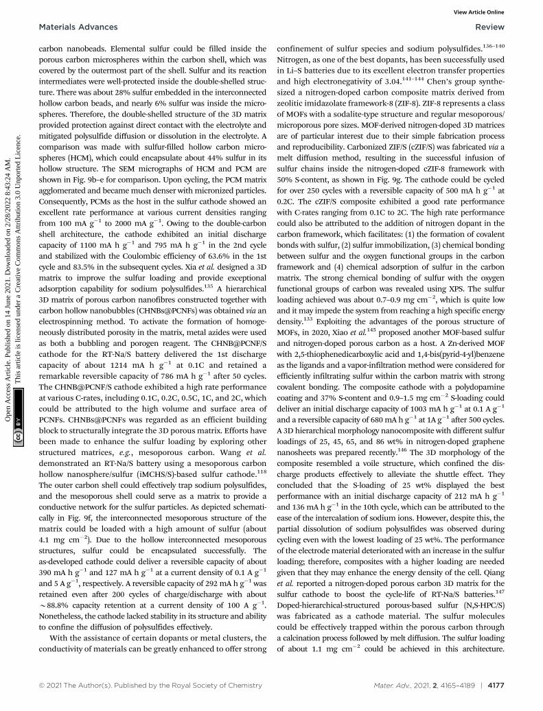
Other possible configurations of the 3D matrix to enhancethe sulfur loading and concomitantly inhibit polysulfide dis-solution have also been developed. One of these configurationswas proposed by Lee et al.,134 where they synthesized hollowcarbon sphere/sulfur (HCS-S) with the sulfur content of about56 wt% using a one-step hydrothermal method. The majority ofthe sulfur content was successfully impregnated within thering-shaped hollow spheres. The cell could deliver a reversiblecapacity of 550 mA h g�1. Zhang et al. contributed towardsimproving the battery performance by assembling porous carbonmicrospheres (PCMs) as a 3D matrix to support sulfur particles.132
Multi-dimensional framework PCMs were constructed as a double-shell architecture with the outer carbon shell consisting ofmicronized-carbon shells and an inner carbon shell, with hollow
Fig. 9 (a) Schematic representation of the material processing steps using sucrose (sugar) to produce microporous sodium–sulfur battery cathodes.Reproduced with permission.117 Copyright 2017, the American Chemical Society. SEM images of (b) HCM, (c) HCMs-S, (d) PCM and (e) PCMs-S.Reproduced with permission.132 Copyright 2018, the American Chemical Society. (f) Schematic of the confinement in the S@iMCHS nanocomposite.Reproduced with permission.118 Copyright 2016, the American Chemical Society. (g) Procedure for the fabrication of c-ZIF-8/S. Reproduced withpermission.133 Copyright 2016, The Royal Society of Chemistry. (h) Schematic illustration of the synthesis S@Con-HC. (i) Cycling performance of S@Con-HC and S@HC. Reproduced with permission.70 Copyright 2018, Springer Nature.
Review Materials Advances
Ope
n A
cces
s A
rtic
le. P
ublis
hed
on 1
4 Ju
ne 2
021.
Dow
nloa
ded
on 2
/28/
2022
8:4
3:24
AM
. T
his
artic
le is
lice
nsed
und
er a
Cre
ativ
e C
omm
ons
Attr
ibut
ion
3.0
Unp
orte
d L
icen
ce.
View Article Online
© 2021 The Author(s). Published by the Royal Society of Chemistry Mater. Adv., 2021, 2, 4165–4189 | 4177
carbon nanobeads. Elemental sulfur could be filled inside theporous carbon microspheres within the carbon shell, which wascovered by the outermost part of the shell. Sulfur and its reactionintermediates were well-protected inside the double-shelled struc-ture. There was about 28% sulfur embedded in the interconnectedhollow carbon beads, and nearly 6% sulfur was inside the micro-spheres. Therefore, the double-shelled structure of the 3D matrixprovided protection against direct contact with the electrolyte andmitigated polysulfide diffusion or dissolution in the electrolyte. Acomparison was made with sulfur-filled hollow carbon micro-spheres (HCM), which could encapsulate about 44% sulfur in itshollow structure. The SEM micrographs of HCM and PCM areshown in Fig. 9b–e for comparison. Upon cycling, the PCM matrixagglomerated and became much denser with micronized particles.Consequently, PCMs as the host in the sulfur cathode showed anexcellent rate performance at various current densities rangingfrom 100 mA g�1 to 2000 mA g�1. Owing to the double-carbonshell architecture, the cathode exhibited an initial dischargecapacity of 1100 mA h g�1 and 795 mA h g�1 in the 2nd cycleand stabilized with the Coulombic efficiency of 63.6% in the 1stcycle and 83.5% in the subsequent cycles. Xia et al. designed a 3Dmatrix to improve the sulfur loading and provide exceptionaladsorption capability for sodium polysulfides.135 A hierarchical3D matrix of porous carbon nanofibres constructed together withcarbon hollow nanobubbles (CHNBs@PCNFs) was obtained via anelectrospinning method. To activate the formation of homoge-neously distributed porosity in the matrix, metal azides were usedas both a bubbling and porogen reagent. The CHNB@PCNF/Scathode for the RT-Na/S battery delivered the 1st dischargecapacity of about 1214 mA h g�1 at 0.1C and retained aremarkable reversible capacity of 786 mA h g�1 after 50 cycles.The CHNB@PCNF/S cathode exhibited a high rate performanceat various C-rates, including 0.1C, 0.2C, 0.5C, 1C, and 2C, whichcould be attributed to the high volume and surface area ofPCNFs. CHNBs@PCNFs was regarded as an efficient buildingblock to structurally integrate the 3D porous matrix. Efforts havebeen made to enhance the sulfur loading by exploring otherstructured matrices, e.g., mesoporous carbon. Wang et al.demonstrated an RT-Na/S battery using a mesoporous carbonhollow nanosphere/sulfur (iMCHS/S)-based sulfur cathode.118
The outer carbon shell could effectively trap sodium polysulfides,and the mesoporous shell could serve as a matrix to provide aconductive network for the sulfur particles. As depicted schemati-cally in Fig. 9f, the interconnected mesoporous structure of thematrix could be loaded with a high amount of sulfur (about4.1 mg cm�2). Due to the hollow interconnected mesoporousstructures, sulfur could be encapsulated successfully. Theas-developed cathode could deliver a reversible capacity of about390 mA h g�1 and 127 mA h g�1 at a current density of 0.1 A g�1
and 5 A g�1, respectively. A reversible capacity of 292 mA h g�1 wasretained even after 200 cycles of charge/discharge with aboutB88.8% capacity retention at a current density of 100 A g�1.Nonetheless, the cathode lacked stability in its structure and abilityto confine the diffusion of polysulfides effectively.
With the assistance of certain dopants or metal clusters, theconductivity of materials can be greatly enhanced to offer strong
confinement of sulfur species and sodium polysulfides.136–140
Nitrogen, as one of the best dopants, has been successfully usedin Li–S batteries due to its excellent electron transfer propertiesand high electronegativity of 3.04.141–144 Chen’s group synthe-sized a nitrogen-doped carbon composite matrix derived fromzeolitic imidazolate framework-8 (ZIF-8). ZIF-8 represents a classof MOFs with a sodalite-type structure and regular mesoporous/microporous pore sizes. MOF-derived nitrogen-doped 3D matricesare of particular interest due to their simple fabrication processand reproducibility. Carbonized ZIF/S (cZIF/S) was fabricated via amelt diffusion method, resulting in the successful infusion ofsulfur chains inside the nitrogen-doped cZIF-8 framework with50% S-content, as shown in Fig. 9g. The cathode could be cycledfor over 250 cycles with a reversible capacity of 500 mA h g�1 at0.2C. The cZIF/S composite exhibited a good rate performancewith C-rates ranging from 0.1C to 2C. The high rate performancecould also be attributed to the addition of nitrogen dopant in thecarbon framework, which facilitates: (1) the formation of covalentbonds with sulfur, (2) sulfur immobilization, (3) chemical bondingbetween sulfur and the oxygen functional groups in the carbonframework and (4) chemical adsorption of sulfur in the carbonmatrix. The strong chemical bonding of sulfur with the oxygenfunctional groups of carbon was revealed using XPS. The sulfurloading achieved was about 0.7–0.9 mg cm�2, which is quite lowand it may impede the system from reaching a high specific energydensity.133 Exploiting the advantages of the porous structure ofMOFs, in 2020, Xiao et al.145 proposed another MOF-based sulfurand nitrogen-doped porous carbon as a host. A Zn-derived MOFwith 2,5-thiophenedicarboxylic acid and 1,4-bis(pyrid-4-yl)benzeneas the ligands and a vapor-infiltration method were considered forefficiently infiltrating sulfur within the carbon matrix with strongcovalent bonding. The composite cathode with a polydopaminecoating and 37% S-content and 0.9–1.5 mg cm�2 S-loading coulddeliver an initial discharge capacity of 1003 mA h g�1 at 0.1 A g�1
and a reversible capacity of 680 mA h g�1 at 1A g�1 after 500 cycles.A 3D hierarchical morphology nanocomposite with different sulfurloadings of 25, 45, 65, and 86 wt% in nitrogen-doped graphenenanosheets was prepared recently.146 The 3D morphology of thecomposite resembled a voile structure, which confined the dis-charge products effectively to alleviate the shuttle effect. Theyconcluded that the S-loading of 25 wt% displayed the bestperformance with an initial discharge capacity of 212 mA h g�1
and 136 mA h g�1 in the 10th cycle, which can be attributed to theease of the intercalation of sodium ions. However, despite this, thepartial dissolution of sodium polysulfides was observed duringcycling even with the lowest loading of 25 wt%. The performanceof the electrode material deteriorated with an increase in the sulfurloading; therefore, composites with a higher loading are neededgiven that they may enhance the energy density of the cell. Qianget al. reported a nitrogen-doped porous carbon 3D matrix for thesulfur cathode to boost the cycle-life of RT-Na/S batteries.147
Doped-hierarchical-structured porous-based sulfur (N,S-HPC/S)was fabricated as a cathode material. The sulfur moleculescould be effectively trapped within the porous carbon througha calcination process followed by melt diffusion. The sulfur loadingof about 1.1 mg cm�2 could be achieved in this architecture.
Materials Advances Review
Ope
n A
cces
s A
rtic
le. P
ublis
hed
on 1
4 Ju
ne 2
021.
Dow
nloa
ded
on 2
/28/
2022
8:4
3:24
AM
. T
his
artic
le is
lice
nsed
und
er a
Cre
ativ
e C
omm
ons
Attr
ibut
ion
3.0
Unp
orte
d L
icen
ce.
View Article Online

4178 | Mater. Adv., 2021, 2, 4165–4189 © 2021 The Author(s). Published by the Royal Society of Chemistry
The presence of nitrogen improved the electrostatic interactionbetween the matrix and sodium polysulfides, which enhanced theentrapment of sodium polysulfides to inhibit side reactions. Guoet al. reported the synthesis of a unique 3D matrix of nickelconcatenated by nitrogen doped on carbon fibres (NCFs) via anelectrostatic spinning method.140 Each unit of nickel displayed ahollow morphology and could successfully buffer the volumechanges during the charge–discharge cycles and also providepolar interactions bonds between Ni and S upon S-loading.Nickel, in combination with NCFs as the host for the S-cathode,exhibited a high rate capability ranging from 0.2C to 5C with areversible capacity of 738.7 and 181.7 mA h g�1, respectively. Inaddition, the cathode could maintain the 1st discharge capacity ofB431 mA h g�1 and B233 mA h g�1 after 270 cycles at 1C due tothe high catalytic effect of the nickel units. However, despite theintriguing rate performance, the cathode could maintain an arealoading of only about 0.5–0.7 mg cm�2. Another approach toenhance the loading of sulfur and prevent the dissolution ofpolysulfides was proposed by Zhang and co-workers.70 Theyused atomic cobalt as an effective electro-catalyst to acceleratethe conversion reactions. As schematically illustrated in Fig. 9h,atomic cobalt and the elemental sulfur particles were efficientlyencapsulated within the hollow framework of the porous carbonnanoparticles. A sulfur loading as high as 5 mg cm�2 couldbe achieved. Electron microscopy revealed uniformly dispersedatomic cobalt and sulfur particles within the carbon nano-particles. The hollow carbon and atomic cobalt could effectivelytrap and bind with polysulfides, respectively, to improve the
stability of the cell for over 600 cycles at a current density of100 mA g�1, as shown in Fig. 9i.
To effectively harness the benefits of the transition metalsulfides to accelerate the reversible reactions, while controllingthe diffusion of polysulfides in the electrolyte solution, Meyersonet al.148 reported a molybdenum sulfide-based sulfur cathode withan active mass loading of about 1.5–2.0 mg cm�2. SEM micro-graphs were captured for the as-developed molybdenum sulfide(i.e., MoS5.6) before cycling, showing angular-shaped particles ofseveral micrometers. After ten cycles, the angular-shaped particlestransformed into spherical structures particles with a reducedlateral size (see Fig. 10a–d). However, although the transformationof the angular-shaped particles into spherical particles increasedthe accessibility of sodium ions into the sodiation active sites,cracks were observed during long-term cycling. The MoS5.6 electrodeshowed a capacity of 537 mA h g�1 and 200 mA h g�1 at currentdensities of 50 mA g�1 and 1 A g�1, respectively.
Recently, Yan et al.139 examined a nitrogen-doped porouscarbon network to embed nickel sulfide nanocrystals as thesulfur cathode for RT-Na/S batteries. A high content of about56% of sulfur in NiS2@NPCTs/S or a sulfur loading of about2.5 mg cm�2 was achieved. The existence of two different typesof sulfur atoms was confirmed by X-ray photoelectron spectro-scopy (XPS). Due to the sulfur loading, NiS2@NPCTs/S as thecathode material exhibited distinct plateaus with a high capacityof 960 mA h g�1 in the 1st cycle, which remained stable at410 mA h g�1 after 750 cycles, as shown in Fig. 10e. The highperformance and increased sulfur loading were attributed to the
Fig. 10 Scanning electron micrographs of the MoS5.6 electrode (a and b) before cycling and (c and d) after 10 cycles at 50 mA g�1. Reproduced withpermission.148 Copyright 2020, the American Chemical Society. (e) Corresponding charge/discharge profiles of NiS2@NPCTs/S at different cycles.(f) Ultraviolet/visible (UV-vis) spectra and corresponding photographs (inset) of pure Na2S6 solution and the solution after exposure to NiS2@NPCTs andNPCTs. Reproduced with permission.139 Copyright 2019 Springer Nature.
Review Materials Advances
Ope
n A
cces
s A
rtic
le. P
ublis
hed
on 1
4 Ju
ne 2
021.
Dow
nloa
ded
on 2
/28/
2022
8:4
3:24
AM
. T
his
artic
le is
lice
nsed
und
er a
Cre
ativ
e C
omm
ons
Attr
ibut
ion
3.0
Unp
orte
d L
icen
ce.
View Article Online

© 2021 The Author(s). Published by the Royal Society of Chemistry Mater. Adv., 2021, 2, 4165–4189 | 4179
synergistic effects of the transition metal sulfide with N-dopedcarbon network, which was confirmed by the UV visible spectra,as shown in Fig. 10f. However, although the cathode based onthe N-doped 3D matrix could maintain an impressive cyclingperformance and relatively high sulfur loading, irreversible lossesin the capacity were observed. Aslam and co-workers studied apolar metal chalcogenide as a matrix for the sulfur cathode inthe RT-Na/S battery.116 A bipyramidal prism structure of cobaltsulfide was fabricated via simple reflux, as shown in Fig. 11a.A high sulfur content of about 64.5% or a sulfur loading of about4.4 mg cm�2 could be obtained through this method. In contrastto the non-polar sulfur matrix, the polar matrix could physicallyblock the outward diffusion of sodium polysulfides. The sulfurand its reduced products could be successfully entrappedthrough the polar sites and wide hollow cavity architecture,
as depicted schematically in Fig. 11b and c. The CoS2/C (BPCS)cathode exhibited an interweaving hierarchical architecturewith wide internal hollow spaces of about 376 nm to entrapthe polysulfides. BPCS displayed a high discharge capacity of1347 mA h g�1 in the 1st cycle, and 755 mA h g�1 in the 2nd cycle,and 701 mA h g�1 after 350 cycles with a high coulombicefficiency of 98.5%. The sulfur loadings of about 7.3 mg cm�2
and 9.1 mg cm�2 were also obtained, and the sulfur cathode wascycled at a rate of 0.5C, where the 1st areal capacity of about6.24 mA h cm�2 and 8 mA h cm�2 was achieved, respectively.Simultaneously, they retained a capacity of 5.5 mA h cm�2 and6.6 mA h cm�2 after ten cycles, respectively. The CoS2/C cathodepresented a new reaction pathway to facilitate the reductionprocess from S to Na2S by mitigating the dissolution of sodiumpolysulfides in the electrolyte. Therefore, this may diminish the
Fig. 11 (a) Synthesis of metal chalcogenide S@BPCX composites. (b) Diffusion of NaPSs in solid nonpolar host. (c) Suppression of NaPSs in hollow polar/catalytic host. Reproduced with permission.116 Copyright 2020, Springer Nature. (d) Cyclic voltammetry curves of the rGO/S/MnxOy@SA–PANI cathodeat a scan rate of 20 mV s�1. (e) Schematic of the possible surface redox reaction between Na2S6 and MnxOy. Reproduced with permission.61 Copyright2019, the American Chemical Society.
Materials Advances Review
Ope
n A
cces
s A
rtic
le. P
ublis
hed
on 1
4 Ju
ne 2
021.
Dow
nloa
ded
on 2
/28/
2022
8:4
3:24
AM
. T
his
artic
le is
lice
nsed
und
er a
Cre
ativ
e C
omm
ons
Attr
ibut
ion
3.0
Unp
orte
d L
icen
ce.
View Article Online

4180 | Mater. Adv., 2021, 2, 4165–4189 © 2021 The Author(s). Published by the Royal Society of Chemistry
shuttle effect to provide better electrochemical performance evenwith a higher sulfur loading.
One of the issues of increasing the thickness of the sulfurloading is the rapid dissolution of sulfur products due to thedrop in the capillary pressure.119 In addition, a restrictedreaction pathway for sodium ions and electrons, and dramaticvolumetric changes are observed with an increased loading.Thus, rationally reinforcing different composites of reducedgraphene oxide (rGO) and manganese oxide (MnxOy) with Naalginate/polyaniline hybrid binder to form a 3D matrix may beanother effective approach to mitigate these issues.61 To designthis type of interconnected 3D matrix, Ghosh and co-workersdesigned a rGO/S/MnxOy@SA–PANI composite cathode via avacuum filtration method, which resulted in a sulfur loading ofabout 2.05 mg cm�2. Owing to the good electrical conductivityof rGO (4.8 � 103 S m�1) and cubic lattice structure of theMnxOy nanoparticles, the as-synthesized 3D conductive matrixwith porous interconnected morphology could accommodatevolume fluctuations during the reversible sodiation and deso-diation reactions. Cyclic voltammetry was performed using thecomposite cathode, as shown in Fig. 11d, showing a series ofcathodic peaks in the range of 1.2–2.8 V vs. Na/Na+, corres-ponding to: (1) the conversion of solid-phase S8 to liquid-phaselong-chain polysulfides, (2) long-chain polysulfides to liquid-phasemiddle-chain polysulfides, and (3) middle-order polysulfides toinsoluble short-chain polysulfides, respectively. The charge/dis-charge curve for the composite cathode showed an enhancedperformance in the 1st, 2nd and 5th cycles at a current densityof 0.2 A g�1. As a result of the enhanced ionic-electron distributionefficiency, the diffusion pathways of sodium ions and electronscould be shortened, contributing to the improved conversionreactions with minimal dissolution of polysulfides. In addition,MnxOy nanoparticles could act as a reducing agent for polysulfides,resulting in a high affinity of MnxOy nanoparticles (30–50 nm)towards Na2S6, which is evident in Fig. 11e. The sulfur cathodecomprised of rGO/S/MnxOy@SA–PANI could deliver a remarkableenergy density of 737 W h kg�1. The high performance of thecathode was attributed to the electrocatalytic activity of the MnxOy
nanoparticles and the conductive nature of the rGO/S/MnxOy@SA–PANI composites. However, with an increase in the number ofcycles, a gradual decay was observed in the reversible capacities,which could be due to the formation of a thick SEI on the surface ofthe anode, affecting the dissolution and deposition of sodium ions.
The inhomogeneous distribution of sulfur within the matrixoften leads to the low utilization of sulfur, which has become aroadblock to reach the unprecedented specific capacity of theRT-Na/S battery.134,149,150 In the pursuit of developing an idealhost for elemental sulfur and confining the polysulfides, researchershave reported different composites in various structures, whichhave been found to be suitable for achieving a high sulfurloading cathode. One unique contribution was reported by Yuand Manthiram, where they explored different sodium/polysulfidebatteries based on different composite materials.151 They designeda cathode composed of long-chain sodium polysulfides with highsurface area multi-walled carbon nanotube (MWCNT) fabric,which served as the current collector for the sulfur cathode.
The cycling performance of the dissolved liquid-phase NaPScatholyte/MWCNT with 60% sulfur content was investigated at adischarge cut-off voltage of 1.2 V for 30 cycles, which maintained acapacity of about 400 mA h g�1. NaPSs/MWCNT exhibited a sharpdecay in capacity after the first few cycles, which could be due tothe sluggish reversibility of the sodium polysulfides after thecharge/discharge cycles. By varying the concentration of thesodium polysulfide catholyte in the composite material, the sulfurloading could be further enhanced. Therefore, Yu et al. performedfurther studies, but this time with short-chain polysulfides (Na2S)(80%), which were spread on MWCNT (20%) to enhance theconductivity of the insulated Na2S.152 Na2S, as they claimed,possesses ‘‘high electronic resistivity and low sodium ion diffusivity,’’behaving as a special cathode with a high anchoring effectthat is enough to encapsulate the charge/discharge productsduring the cycling process. The cell with the Na2S compositecathode was tested at two different C-rates with a dischargecapacity of 660 mA h g�1 at C/10 and 540 mA h g�1 at C/3. Thecell exhibited a cycle life of about 50 cycles, retaining capacities of560 mA h g�1 and 380 mA h g�1, and a Coulombic efficiency ofB90% after the subsequent cycles. As a result of its uniquearchitecture with good electron-ionic transport, the Na2S/MWCNTelectrode exhibited an energy density of B250 W h kg�1. However,the cell experienced high polarization with an increase in rate dueto the inert nature of Na2S. In another contribution, they proposeda conductive matrix of carbon nanofibres anchored withhigh surface area activated carbon.153 The sulfur content of about40–50 wt% could be accommodated within this matrix. CNF/ACwas utilized as the matrix for the sodium polysulfide cathode toenhance the utilization of sulfur in the polysulfides. Recently, Bloiand co-workers revisited this configuration using nanostructuredNa2S (90 wt%) with conductive carbon as the matrix for the sulfurcathode.154 The Na2S/C hybrid cathode, which was synthesizedvia carbothermal reduction at different temperatures, showedimproved cathode utilization with enhanced stability and an initialdischarge capacity of about 740 mA h g�1. One of the methods toachieve a higher and stronger adsorption of polysulfides can berealized by incorporating Na2S6 catholyte into a carbon cloth/MnO2
nanoarray.155 Carbon cloth/MnO2 showed a strong anchoring effecttowards higher-order polysulfides, alleviating the shuttle effect andaccelerating the reversibility and reaction kinetics. A sulfur loadingof about 1.7 mg cm�2 was attained. The CC/MnO2@Na2S6 cathodedisplayed an initial specific capacity of B938 mA h g�1 with 67%retention after 500 cycles. Table 1 comprehensively summarizes theefforts made hitherto to enhance the sulfur loading and the cellperformance. Despite the advantages offered by the judiciouscombination of different composite materials, dedicated effortsare still required to engineer matrix materials for the sulfur cathode.
3. Status of Na metal anode andelectrolyte engineering
Owing to its high theoretical capacity (1166 mA h g�1), lowelectrochemical potential (�2.71 V) with respect to the standardhydrogen electrode, high abundance and cost effectiveness, the
Review Materials Advances
Ope
n A
cces
s A
rtic
le. P
ublis
hed
on 1
4 Ju
ne 2
021.
Dow
nloa
ded
on 2
/28/
2022
8:4
3:24
AM
. T
his
artic
le is
lice
nsed
und
er a
Cre
ativ
e C
omm
ons
Attr
ibut
ion
3.0
Unp
orte
d L
icen
ce.
View Article Online

© 2021 The Author(s). Published by the Royal Society of Chemistry Mater. Adv., 2021, 2, 4165–4189 | 4181
Tab
le1
Co
mp
aris
on
of
the
diff
ere
nt
mat
rice
so
fth
esu
lfu
rca
tho
de
for
RT
/Na–
Sb
atte
rie
sin
the
lite
ratu
re
Mat
rix
phys
ioch
emis
try
Cat
hod
esy
stem
Syn
thes
isro
ute
Act
ive
mas
s-lo
adin
g(m
gcm�
2 )
Init
ial
dis
char
ge(m
Ah
g�1)
Cap
acit
y(m
Ah
g�1)
afte
rn
cycl
esA
dva
nta
ges
Dis
adva
nta
ges
Che
mic
alas
pect
sC
hem
ical
bind
ing
Poly
acry
lic
acid
-bas
edSP
AN
54
Hea
ttr
eatm
ent
1.1–
1.8
1195
@0.
5C10
00at
1000
cycl
es@
0.5C
Acc
omm
odat
evo
lum
etri
cfl
uct
uat
ion
sd
ue
tost
ron
gbi
nd
ing
Low
mas
slo
adin
gof
sulf
ur
Sod
ium
algi
nat
eba
sed
rGO
/S/M
nxO
y61
Vac
uu
mfi
ltra
tion
2.05
470
0@0.
12C
(0.2
Ag�
1)
535
afte
r50
cycl
es@
0.12
C(0
.2A
g�1)
Faci
lita
ted
ion
-diff
usi
onpr
oces
sw
ith
cycl
eli
feu
pto
400
cycl
esLo
wcu
rren
td
ensi
ties
Car
bon
–su
lfu
r90/
rGO
30
Th
erm
alri
ng-
open
ing
poly
mer
isat
ion
2.14
B50
0@0.
6C(1
Ag�
1)
285
afte
r10
0cy
cles
@0.
6C(1
Ag�
1)
Larg
eS-
con
fin
emen
tan
dim
prov
edra
teca
pabi
lity
Lim
ited
curr
ent
den
siti
es
Cov
alen
tsu
lfu
r–ca
rbon
com
plex
(SC
-BD
SA)6
2C
alci
nat
ion
and
ther
-m
altr
eatm
ent
34
900@
0.06
C(0
.1A
g�1)
590
afte
r20
0cy
cles
@0.
06C
(0.1
Ag�
1)
Hig
han
chor
ing
abil
ity
tofo
rmin
solu
ble
inte
rmed
iate
sLo
wsu
lfu
rco
nte
nt
Sulf
ur
into
carb
onm
atri
x(S
C)6
3C
arbo
niz
edcr
oss-
lin
kin
gpo
lym
eris
atio
n0.
9–1.
1B
1070
@0.
06C
(0.1
Ag�
1)
500
afte
r10
0cy
cles
@0.
06C
(0.1
Ag�
1)
Fast
kin
etic
con
vers
ion
tosh
ort-
chai
npo
lysu
lfid
esV
ery
low
S-co
nte
nt(
21.5
%)a
nd
load
ing
wit
hca
paci
tyd
ecay
inin
itia
lfe
wcy
cles
Dop
ant
Ato
mic
coba
lt-h
ollo
wca
rbon
nan
osph
eres
70
Sol–
gel
proc
ess
510
81@
0.06
C(0
.1A
g�1)
508
afte
r60
0cy
cles
@0.
06C
(0.1
Ag�
1)
Impr
oved
sulf
ur
reac
tivi
ty,
hig
hsu
lfu
ru
tili
sati
on&
alle
viat
edpo
lysu
lfid
ed
iffu
sion
du
eto
pola
rin
tera
ctio
ns
Part
ial
reve
rsib
ilit
yof
Na 2
Spr
odu
ct
Hig
hsu
rfac
ear
eam
esop
orou
sca
rbon
–co
pper
/su
lfu
r73
Solu
tion
impr
egn
atio
nst
rate
gy1.
010
00@
0.03
C61
0af
ter
110
cycl
es@
0.03
CSt
able
reve
rsib
leca
paci
ties
wit
hgo
odra
teca
pabi
lity
Low
term
cycl
icpe
rfor
man
cew
ith
low
load
ing
ofac
tive
mat
eria
lN
itro
gen
-dop
edca
rbon
nan
osph
eres
load
edw
ith
iron
74
Car
both
erm
alre
du
ctio
nfo
llow
edby
calc
inat
ion
proc
ess
—4
350@
0.6C
(1A
g�1)
180
afte
r20
0cy
cles
@1
Ag�
1A
ccel
erat
edco
nve
rsio
nre
acti
onan
dsh
orte
rd
iffu
sion
path
for
ion
san
del
ectr
ons
Low
erca
paci
tyat
tain
edfo
rlo
wva
lues
ofcu
rren
td
ensi
tyan
dsi
de
reac
tion
sbe
twee
nso
l-ve
nts
and
poly
sulf
ides
.G
old
nan
odot
son
hie
rarc
hic
alN
-dop
edca
rbon
mic
rosp
her
es/
sulf
ur7
1
HC
let
chin
gpr
oces
s—
1967
@0.
06C
(0.1
Ag�
1)
701
afte
r110
cycl
es@
0.1
Ag�
1E
nh
ance
dsu
lfu
ru
tili
zati
on&
adso
rpti
onca
pabi
lity
Dec
ayin
capa
city
wit
han
incr
ease
incy
cle
nu
mbe
r
Tel
luri
um
-dop
ed/
SPA
N7
2H
eat
trea
tmen
tm
eth
od1.
0–1.
2B
1500
@0.
3C(0
.5A
g�1)
970
afte
r60
0cy
cles
@0.
3C(0
.5A
g�1)
Fast
erki
net
icre
acti
ons
&go
odpe
rfor
man
cein
both
eth
eran
dca
rbon
ate-
base
del
ectr
olyt
e
Ver
ylo
wac
tive
mas
slo
adin
gsan
dlo
wcu
rren
td
ensi
ties
Phys
ical
aspe
ct1D m
atri
xcP
AN
S83
Ele
ctro
spin
nin
gm
eth
od1.
0–1.
236
4@0.
1C15
3af
ter
500
cycl
es@
1CSt
able
cycl
ing
test
,im
prov
edki
net
ics
for
de-
sod
iati
on&
hig
hra
teca
pabi
lity
up
to6C
Low
reve
rsib
leca
paci
ties
wit
hin
crea
sed
C-r
ates
Pyro
lyze
dPA
N/
sele
niu
md
isu
lfid
e84
Ele
ctro
spin
nin
gm
eth
od&
hea
ttr
eatm
ent
210
43@
0.6C
(1A
g�1)
800
afte
r40
0cy
cles
@1
Ag�
1E
xtre
me
stab
lecy
clic
life
Low
volt
age
plat
eau
&li
mit
edin
trin
sic
reac
tivi
ty
C/S
/BaT
iO3@
tita
niu
md
ioxi
de8
5E
lect
rosp
inn
ing
tech
-n
iqu
ean
dat
omic
laye
rd
epos
itio
n
3.3–
3.5
952@
0.6C
(1A
g�1)
524.
8af
ter
1400
cycl
es@
0.6C
(1A
g�1)
Ult
ra-lo
ng
term
cycl
icst
abil
ity
&st
able
ion
ictr
ansp
ort
inte
rfac
eLo
wm
ass
load
ings
2D mat
rix
Nan
ocar
bon
-pro
mot
edco
mm
-S9
8B
all
mil
lin
gpr
oces
s0.
8–2.
071
3@0.
2C70
0af
ter
200
cycl
es@
0.2C
(for
1.2
mg
cm�
2)
Hig
hbi
nd
ing
affin
ity
tow
ard
ssu
lfu
ran
dit
sd
isch
arge
prod
uct
san
dco
st-e
ffici
ent
Low
load
ing
ofsu
lfu
rw
ith
low
C-r
ate
SPA
N8
2Py
roly
sis
met
hod
—34
2@0.
1C26
6af
ter
200
cycl
es@
0.1C
Hig
hfl
exib
ilit
y,ro
llab
ilit
y&
ben
dab
ilit
yto
1801
wit
hou
tan
yfr
actu
re
Aco
nti
nu
ous
volt
age
dec
ayin
the
firs
td
isch
arge
S/C
PAN
10
9H
eat
trea
tmen
tB
0.79
B31
0@0.
06C
(0.1
Ag�
1)
251
afte
r10
0cy
cles
@0.
06C
(0.1
Ag�
1)
En
han
ced
ion
icco
nd
uct
ivit
ySh
arp
dec
ayin
init
ialc
ycle
and
low
area
llo
adin
gsC
arbo
nw
rapp
edco
balt
nan
opar
ticl
eson
grap
hen
eae
roge
l11
0
Th
erm
altr
eatm
ent
572.
8@5C
286.
5af
ter
1000
cycl
es@
5CIm
prov
edS-
reac
tivi
tyev
enat
hig
hC
-rat
ean
dac
com
mod
atio
nof
fast
volu
me
flu
ctu
atio
ns
Low
S-co
nte
nt
ofon
lyab
out
37.5
%
Materials Advances Review
Ope
n A
cces
s A
rtic
le. P
ublis
hed
on 1
4 Ju
ne 2
021.
Dow
nloa
ded
on 2
/28/
2022
8:4
3:24
AM
. T
his
artic
le is
lice
nsed
und
er a
Cre
ativ
e C
omm
ons
Attr
ibut
ion
3.0
Unp
orte
d L
icen
ce.
View Article Online

4182 | Mater. Adv., 2021, 2, 4165–4189 © 2021 The Author(s). Published by the Royal Society of Chemistry
Tab
le1
(co
nti
nu
ed)
Mat
rix
phys
ioch
emis
try
Cat
hod
esy
stem
Syn
thes
isro
ute
Act
ive
mas
s-lo
adin
g(m
gcm�
2 )
Init
ial
dis
char
ge(m
Ah
g�1)
Cap
acit
y(m
Ah
g�1)
afte
rn
cycl
esA
dva
nta
ges
Dis
adva
nta
ges
3D mat
rix
Car
bon
fibr
ecl
oth
/su
lfu
r11
1So
luti
onim
preg
nat
ion
139
0@0.
1C12
0af
ter
300
cycl
es@
0.1C
(for
2m
gcm�
2)
Hig
hel
ectr
olyt
eab
sorb
abil
ity
&fl
exib
ilit
yIn
crea
sed
pola
riza
tion
wit
hin
crea
sed
load
ing
Suga
r-d
eriv
edm
icro
-po
rou
sca
rbon
/su
lfu
r11
7Is
oth
erm
alva
por
phas
ein
filt
rati
on—
B15
24@
0.1C
300
afte
r15
00cy
cles
@1C
Stab
leSE
Ila
yer
&st
ron
gaffi
nit
yfo
rsu
lfu
rsp
ecie
sLo
wen
ergy
den
sity
poss
ible
Ult
ra-m
icro
poro
us
carb
on/s
ulf
ur9
0Si
ngl
est
eppo
lym
erca
rbon
isat
ion
34
900@
0.1C
392
afte
r20
0cy
cles
@1C
Eff
ecti
veco
nfi
nem
ent
betw
een
carb
onan
dsu
lfu
rm
olec
ule
sSl
ugg
ish
kin
etic
sof
sod
ium
ion
sPo
rou
sca
rbon
mic
ro-
sph
eres
/su
lfu
r13
2C
hem
ical
vapo
ur
dep
osit
ion
—11
00@
0.06
C(0
.1A
g�1)
290
afte
r35
0cy
cles
@0.
1A
g�1
En
han
ced
poro
sity
toac
com
-m
odat
evo
lum
efl
uct
uat
ion
s&
impr
oved
stru
ctu
red
stab
ilit
y
Cap
acit
ylo
ss
Car
bon
hol
low
nan
o-bu
bble
s@Po
rou
sca
rbon
nan
ofib
res/
sulf
ur1
35
Ele
ctro
spin
nin
gte
chn
iqu
e1.
412
14@
0.1C
256
afte
r40
0cy
cles
@2C
En
han
ced
adso
rpti
onca
pabi
lity
,h
igh
sulf
ur
uti
liza
tion
wit
hh
igh
reve
rsib
ilit
y
Low
S-lo
adin
g
Mes
opor
ous
carb
onh
ollo
wn
anos
pher
es/
sulf
ur1
18
Sol–
gel
met
hod
3.2–
4.1
1215
@0.
06C
(0.1
Ag�
1)
292
afte
r20
0cy
cles
@0.
06C
(0.1
Ag�
1)
Impr
oved
con
du
ctiv
ity
&h
igh
Sel
ectr
oact
ivit
ySl
owki
net
ics
and
seri
ous
pola
riza
tion
wit
hin
crea
sed
nu
mbe
rof
cycl
esM
OF-
der
ived
S,N
-dop
edpo
rou
sca
rbon
14
5V
apor
-in
filt
rati
onm
eth
od0.
9–1.
510
03@
0.06
C(0
.1A
g�1)
680
afte
r50
0cy
cles
@0.
6C(1
Ag�
1)
Stro
ng
cova
len
tbo
nd
ing
and
red
uce
dad
sorp
tion
ener
gyof
NaP
Ss
Low
con
ten
tof
sulf
ur
(37
wt%
)
Nit
roge
n-d
oped
grap
hen
en
anos
hee
ts/
sulf
ur1
46
Ch
emic
alre
acti
ond
epos
itio
n&
low
tem
pera
ture
hea
ttr
eatm
ent
—21
2@0.
05C
48af
ter
300
cycl
es@
0.1C
En
han
ced
tran
spor
tof
sod
ium
ion
s&
incr
ease
dS-
load
ing
ach
ieve
du
pto
86w
t%
Low
con
fin
emen
tof
the
com
posi
teto
sulf
ur
spec
ies,
lead
ing
toa
deca
yin
capa
city
with
incr
ease
dcy
clin
gan
dlo
wer
elec
troc
hem
ical
perf
orm
ance
with
incr
ease
insu
lfur
wt%
N,S
dop
ed-h
iera
rch
ical
poro
us
carb
on1
47
Cu
stom
ised
roll
-to-
roll
lin
est
rate
gies
1.0–
1.1
B43
0@0.
14C
(0.2
3A
g�1)
378
afte
r35
0cy
cles
@0.
14C
(0.2
3A
g�1)
Inh
ibit
sre
acti
onof
sod
ium
poly
sulf
ides
wit
hth
eel
ectr
olyt
e&
impr
oved
wet
tabi
lity
Lim
ited
curr
ent
rate
and
low
erlo
adin
gsof
acti
vem
ater
ial
Nic
kel–
nit
roge
n-d
oped
carb
onfi
bres
14
0E
lect
rost
atic
spin
nin
gpr
oces
s0.
5–0.
7B
431@
1CB
233
afte
r27
0cy
cles
@1C
Goo
dca
taly
tic
effec
tof
Ni
onth
eco
nve
rsio
nof
NaP
SsLo
wel
ectr
och
emic
alpe
rfor
-m
ance
and
low
S-lo
adin
gA
tom
icco
balt
-hol
low
carb
onn
anos
pher
es7
0So
l–ge
lpr
oces
s5
1081
@0.
06C
(0.1
Ag�
1)
508
afte
r60
0cy
cles
@0.
06C
(0.1
Ag�
1)
Impr
oved
sulf
ur
reac
tivi
ty,
hig
hsu
lfu
ru
tili
sati
on&
alle
viat
edpo
lysu
lfid
ed
iffu
sion
du
eto
pola
rin
tera
ctio
ns
Part
ial
reve
rsib
ilit
yof
Na 2
Spr
odu
ct
Mol
ybd
enu
msu
lfid
e14
8C
hem
ical
oxid
atio
n1.
5–2
400@
0.12
C(0
.2A
g�1)
300
afte
r10
0cy
cles
@0.
12C
(0.2
Ag�
1)
Dec
reas
edsi
zeof
com
posi
tem
ater
ial
allo
win
gfa
ster
rate
tran
spor
tof
ion
s
Cap
acit
yd
ecay
and
low
curr
ent
den
sity
valu
es
Nic
kel
sulf
ide@
nit
roge
n-d
oped
poro
us
carb
onn
etw
ork1
39
Free
ze-d
ryin
gfo
llow
edby
hea
ttr
eatm
ent
2.5
960@
0.6C
(1A
g�1)
401
afte
r75
0cy
cles
@0.
6C(1
Ag�
1)
Eff
ecti
veel
ectr
ocat
alyt
icac
tive
site
sw
ith
impr
oved
kin
etic
sto
prom
ote
fast
con
vers
ion
Deg
rad
edca
paci
tyva
lues
wit
hin
crea
sein
curr
ent
den
sity
CoS
2C
@su
lfu
r11
6Si
mpl
ere
flu
xm
eth
od4.
413
47@
0.5C
675
afte
r80
0cy
cles
@0.
5C(f
or4.
4m
gcm�
2)
Succ
essf
ul
entr
apm
ent
ofso
diu
mpo
lysu
lfid
esw
ith
hig
had
sorp
tion
capa
bili
ty
Lim
ited
perf
orm
ance
wit
hin
crea
sein
load
ing
rGO
/S/M
nxO
y@SA
–PA
NI6
1V
acu
um
filt
rati
on2.
054
700@
0.12
C(0
.2A
g�1)
535
afte
r50
cycl
es@
0.12
C(0
.2A
g�1)
Faci
lita
ted
ion
-diff
usi
onpr
oces
sw
ith
cycl
eli
feu
pto
400
cycl
esLo
wcu
rren
td
ensi
ties
Review Materials Advances
Ope
n A
cces
s A
rtic
le. P
ublis
hed
on 1
4 Ju
ne 2
021.
Dow
nloa
ded
on 2
/28/
2022
8:4
3:24
AM
. T
his
artic
le is
lice
nsed
und
er a
Cre
ativ
e C
omm
ons
Attr
ibut
ion
3.0
Unp
orte
d L
icen
ce.
View Article Online

© 2021 The Author(s). Published by the Royal Society of Chemistry Mater. Adv., 2021, 2, 4165–4189 | 4183
sodium anode is considered an appealing candidate as ananode for RT-Na/S batteries.156,157 However, there are numerouschallenges that need to be addressed urgently, which include,but are not limited to the following;
(1) Rapid chemical reactivity of Na metal with electrolyte.158
This leads to the decomposition of the electrolyte on the metalsurface, which creates a layer of by-products, and the instabilityof this layer (solid electrolyte interphase) ultimately results in adecay in performance.
(2) Growth of dendrites.159,160 They are mostly caused becauseof surface protrusions, uneven distribution of current density andnon-uniform deposition of Na, which result in the continuousgrowth of metal dendrites, eventually, short circuiting the system.
(3) Gas evolution.161 The formation of dendrites is one of themain reasons for gas evolution, which accumulates graduallyupon the reaction between electrolyte and metal dendrites.
(4) Volume fluctuations.162,163 This can occur because of theincrease or decrease in the thickness of the deposits, resultingin increased pressure and mechanical stresses.
Thus far, various strategies have been employed to stabilize theNa metal anode. For instance, Gu et al.164 reported an electro-chemical surface polishing approach to achieve an ultra-smoothand ultra-thin SEI for an Na metal anode with an organic/inorganicrich multilayer structure. Jiao et al.165 proposed an implantableartificial protective layer to stabilize an Na metal anode obtainedvia the doctor-blade coating layer technique, where NaF particleswere added to an N-methyl pyrrolidone (NMP) and polyvinylidenefluoride (PVDF) solution, giving a thickness of 20 mm. Zhao’sgroup166 reported the rational design of carbon paper (CP) withN-doped carbon nanotubes (CNTs) for Na deposition as a 3D hostthat can accommodate Na ions. Owing to the good conductivityand high surface area of CP, it was used as a skeleton and theN-doped CNTs effectively reduced the contact angle between the
Na metal and host. Thus far, electrolyte engineering is thesimplest technique to form a nearly ideal artificial solid electro-lyte interphase (SEI), where the reaction between the engineeredelectrolyte and Na metal plays a decisive role. An ideal electro-lyte should possess some characteristic attributes such as:(i) good ionic conductivity (1–10 mS cm�1)167,168 to allow easyaccess to sodium ions, (ii) wide potential window (1.5–4.2 V vs.Na/Na+),169 (iii) not actively participate in the chemical reactionwith a stabilized electrolyte-electrode interfacial contact, (iv) electro-chemical compatibility with the components of the battery systemand must be inflammable, and (v) cost-effective and environmentalbenignancy.33,170 Nevertheless, the aforementioned attributescan be challenging due to the instability of most of organicelectrolytes in the presence of alkali metal anodes, resultingin the formation of a highly uncontrolled solid electrolyteinterface (SEI).171 Thus, continuous research to engineer theelectrolyte has been put forward to achieve most of the desir-able properties. It should be noted that it is crucial to establishan electrolyte system with a suitable solvent, long-term stablesodium salts and additives to ensure the formation of amechanically and chemically stable SEI.172,173 The progressmade in electrolyte engineering is still in its infancy and highlylimited due to its high corrosivity, narrow thermal stabilitywindow of the additives and sodium salts, besides their thermo-dynamic instability in the presence of Na metal.
The concept of designing localized metal-alloy artificial inter-faces is relatively new, which exhibits tremendous potential toboost the stability of alkali metal anodes. Recently, Zheng’sgroup174 devised a new strategy to intrinsically develop a localizedmetal-alloy interphase. The electrolyte was engineered by addinga controlled amount of additive such as SnCl2 to achieve thein situ emergence of an Na–Sn alloy interphase directly over theNa metal anode, as shown in Fig. 12a. The interphase was
Fig. 12 (a) Schematic of SEI generation on Na metal working in a traditional carbonate-based electrolyte, leading to dendrite growth and in situ-formedNaCl-rich SEI with Na–Sn alloy layer, resulting in uniform ion transport and dendrite-free cycling. Reproduced with permission.174 Copyright 2019, theAmerican Chemical Society. (b) Schematic representation of process involved in forming an artificial metal alloy interphase and corresponding SEM images.Reproduced with permission.175 Copyright 2020, Elsevier. (c) Cycling with high cut-off potential, leading to most of the sodiophilic films falling off and cyclingwith low cut-off potential leads to the retention of most of the sodiophilic particles. Reproduced with permission.176 Copyright 2019, John Wiley and Sons.
Materials Advances Review
Ope
n A
cces
s A
rtic
le. P
ublis
hed
on 1
4 Ju
ne 2
021.
Dow
nloa
ded
on 2
/28/
2022
8:4
3:24
AM
. T
his
artic
le is
lice
nsed
und
er a
Cre
ativ
e C
omm
ons
Attr
ibut
ion
3.0
Unp
orte
d L
icen
ce.
View Article Online

4184 | Mater. Adv., 2021, 2, 4165–4189 © 2021 The Author(s). Published by the Royal Society of Chemistry
considered to result from the electrochemical reactions betweenSnCl2 and Na metal, where SnCl2 is reduced to Sn and forms analloy with Na.177,178 A dendrite free anode and stable cycling wereachieved for 500 h with 50 mM SnCl2 added to the EC/PCelectrolyte, showing an improved performance compared to theNa3V2(PO4)3 (NVP) cathode. Although the stability of the anodeimproved, the deposition morphology appeared to be highly non-uniform. Thus, to design and develop a controlled and highlyuniform metal-alloy interphase, an innovative methodology wasproposed recently.175 Generally, Na deposition can allow equili-brium and controlled growth at low current densities in contrastto high current densities, which involve non-equilibrium anduncontrolled growth.179,180 For a perfect interphase, enhancedcritical strain and high Young’s modulus are essential to alloweffective functioning at both low and high current densities. Non-uniform and uncontrolled growth due to volume expansion andcontraction can be handled by high critical strain (ductile).Conversely, controlled and equilibrium growth can be obtainedvia a high Young’s modulus (stiff), alleviating the generation oflarge dendrites.181 For rapid and smooth Na ion transport acrossthe interphase, a low ionic diffusion barrier can be a crucialfactor. For instance, existing SEI products such as NaF possessrelatively large ionic diffusion barriers and Na2O is stiff but a verybrittle ceramic product, whereas organic compounds possesshigh porosity but less stiffness.182,183 Consequently, the currentNa anodes can only show stability at low current densities (0.25 to1 mA cm�2).160,184,185 Thus to circumvent this issue, Kumaret al.186 demonstrated a biphasic interphase (BPI) that was grownby reacting aqueous ammonia vapour with an Na metal anode,consisting of two chemically different phases (NaNH2 andNaOH). NaNH2 shows high ductility with high critical strainand NaOH possesses good stiffness with a high Young’s mod-ulus. Consequently, the BPI showed a smooth track with a lowion diffusion barrier, guiding the ions to dissolve and deposituniformly. As a result, highly stable Na plating/stripping char-acteristics at high current densities (1–50 mA cm�2) and highareal capacities (1–10 mA h cm�2) were obtained. Unlike thesolid–liquid approach, a solid–vapor approach was utilized torealize the formation of highly controlled metal-alloy interphasesdirectly over the Na metal anode. The direct reaction of tin-tetrachloride (SnCl4) vapor with Na metal led to the formation oflocalized metal-alloy interphases instantly. Due to the strongadhesion and enhanced Young’s modulus of elasticity, the inter-phase could accommodate volume fluctuations. Conversely, ahighly compact and uniform layer of metal-alloy ensures effectivescreening of the metal anode, while it provides improved ionicconductivity to the electrolyte ions. Besides exploring Sn-basedalloys, it has been demonstrated that the reduction potential ofthe metal cation is a decisive factor in guaranteeing the for-mation of a metal alloy interphase. The reduction of the metalcation and further formation of an MAI with the Na anode due tothe spontaneity of the reaction (DG o 0) is supported by a highpositive reduction potential with respect to Na. Another strategyto form a sodiophilic metal alloy interphase was proposed byTang et al.176 to enable efficient Na deposition and stripping.They compared the sodiophilicity of Au, Mo, Cr, Cu, Sn and Sb by
electrochemical measurements and reported that only Sb, Au andSn formed an alloy with Na metal.187–189 They further highlightedthe continuous alloying–dealloying resulted in pulverisation ofthe sodiophilic metal alloys, leading to the disappearance of thesodiophilic interphase. A technique for controlling the cut-offpotential was employed and the Na-metal alloy interphase wasbound by binders, as shown in Fig. 12c, resulting in an enhancedperformance. Therefore, the formation of metal-alloy interphasescan be helpful in improving the performance of alkali-metal anodes.
4. Conclusion and future outlook
The physiochemical engineering of the matrix is one of the keyfactors for the development of a stable and high sulfur-loadedsodium–sulfur battery system. Considering the fact that Na+ ionsare relatively bigger and sodium polysulfide are comparativelymore corrosive than their Li analogue, the RT-Na/S battery isexpected to suffer more severely than that of Li–S battery systemduring its operation. With an increase sulfur loading or increasedthickness of the cathode layer, several issues may become promi-nent, for instance, (1) a greater loading of active material in theelectrode can result in material peel-off due to weak interparticleinteraction, (2) as the thickness increases, the resistance increasesdue to the insulating nature of sulfur and (3) limited accessibilityof electrolyte ions.190,191 Thus, various strategies have beendeveloped to enhance the sulfur loading and mitigate polysulfideshuttling without adversely affecting the cell performance, andsome of the important approaches were highlighted in the presentreview. Particularly, basic insight into the chemical binding,strategies for mesoscale assembly, unique architectures, and con-figurational innovation in the cathode were specific concerns. It isapparent from the literature that an improved sulfur loading canbe realized in two ways. Firstly, through increased utilization of thesulfur cathode and mitigating the dissolution of the solubledischarge products during cycling. Secondly, infusing more andmore sulfur into the matrix, and therefore, the matrix plays animportant role in controlling the stability of RT-Na/S batteries. Theprimary focus of this review was to summarize the literaturepresenting novel ideas to alter the physiochemical propertiesof the matrix to enhance the sulfur loading.192 Although thefundamental properties of Na are largely different from Li, thedevelopment of RT-Na/S batteries has also been assisted bythe progress made in Li–S batteries, and particularly the rationaldesign of electrode materials.
Under the premise of a high S-loading, a few strategies canbe proposed to ensure a high specific energy density: (1) use ofmodified and polar separators, (2) highly porous current collectorarchitecture, (3) employing a compatible electrolyte system,(4) developing different functional moieties and judiciouscombination of different binder systems and (5) replacing sulfurwith sulfur-rich composites, for example transition metal sul-fides. These developments have been reported for differentbattery systems to enhance their performance and energydensity, and it is likely that their contribution in RT-Na/S willalso result in positive effects.
Review Materials Advances
Ope
n A
cces
s A
rtic
le. P
ublis
hed
on 1
4 Ju
ne 2
021.
Dow
nloa
ded
on 2
/28/
2022
8:4
3:24
AM
. T
his
artic
le is
lice
nsed
und
er a
Cre
ativ
e C
omm
ons
Attr
ibut
ion
3.0
Unp
orte
d L
icen
ce.
View Article Online

© 2021 The Author(s). Published by the Royal Society of Chemistry Mater. Adv., 2021, 2, 4165–4189 | 4185
In addition to fabricating suitable electrode architectures,an indirect approach is to develop modified separators for inhibit-ing the dissolution and simultaneously resolving the issue of theloss of the active materials. Lin et al.193 studied nickel cobaltiteintroduced into carbon nanofibres (NiCo2O4/CNF) as a modifiedseparator to anchor the polysulfides and accelerate the conversionof long-chain to short-chain polysulfides through the Ni–S and Co–Sbonding structure in an Li/S battery system. The modified separatordemonstrated a well-defined interface with strong affinity towardspolysulfides and rich polar nucleation sites, and thus could act as anaccelerator and catalyze the conversion reactions. NiCo2O4/CNFcould provide pathway for a fast ionic diffusion and electronmobility, resulting in a high S-loading of up to 7.9 mg cm�2.
Given that the design of a compatible electrolyte system isalso important for achieving a stable system with higher safety,gel electrolytes are trailblazing technology for achieving a highS-content in cathode composites. To reach a S-loading of about14 mg cm�2, a state-of-the art design of a highly elastic3D-gel cathode was developed, which comprised an inter-connected co-polymer skeleton (achieved through phase inversionstrategy).194 The phase inversion strategy is a well-known universaltechnique for constructing a porous interconnected-polymericnetwork, and it can open up new pathways for the matrix toaccommodate a high sulfur loading.195 During this process, threecontinuous phases merge, i.e., the S/C composite, the pores phaseand a polymeric phase are formed in one-pot simultaneously,leading to the development of an electronically conductive scaffoldto promote conductive pathways. The tri-continuous structuredmatrix with an electron conductive network consists of inter-penetrable macropores, which can favor electrolyte permeationand a high loading of sulfur. Gel electrolytes have also beenfabricated in a similar fashion with an amorphous fluorinatedco-polymer matrix with high ionic conductivity, rendering highflexibility and suppression of dendritic growth.
The binder is another important component, which isindispensable for achieving greater thickness of sulfur in theelectrode material, and hence a high sulfur loading. However,the conventional way of using binders can limit the diffusion ofelectrolyte given that the binder can fill the spaces in thecarbon matrix, thus resulting in a reduced sulfur loading inthe electrode material.196 The premise of a high specific densitycan be ensured with a high sulfur loading. Recently, Shaibaniand co-workers197 reported an expansion-tolerant architecturewith a new approach to augment the number of active sites toaccommodate a large fraction of active materials. Applying thebridging architecture mechanism,198 dispersion of a high mod-ulus Na–CMC binder could be achieved by forming web-likebridging bonds between the neighbouring particles (withoutfilling the voids of the matrix). A sulfur cathode with a sulfurloading as high as 15 mg cm�2 could be achieved through the‘‘bridging architecture technique.’’ A new strategy of developinga high-loaded sulfur cathode system was recently proposed byChen et al.56 A 3D multifunctional flexible network composedof highly polar groups was developed as a binder for theelemental sulfur powder. The amino group-functionalized net-work encapsulated sulfur particles (AFG)@S and allowed a high
sulfur loading of about 8 mg cm�2 without deteriorating thestability and cycle-life of the cell. Theoretical calculation predictedthe high affinity of the –NH2 groups towards sulfur particles anddissolved lithium polysulfide. In addition, the 3D structure of thenetwork offers abundant absorption or adsorption sites for poly-sulfides. Considering that sodium polysulfides are more solublethan lithium polysulfides, it is expected that they may access theabsorption sites more easily compared to lithium polysulfides.Therefore, designing a functional multi-dimensional structurewith highly polar adsorption sites can be pivotal in improvingthe utilization and loading of sulfur in sulfur cathodes for RT-Na/Sbatteries. Furthermore, Han and co-workers199 formulated theidea of a nucleophilic bi-functional binder with the ability toimmobilize polysulfides within the carbon matrix for achievinga higher thickness of active materials. The combination of a maleateand amine group in a binder provides high efficacy for binding,besides chemical and mechanical stability. The bi-functionalmaleate poly-(ethylene glycol) (PEG) binder resulted in a high sulfurloading of about 12 mg cm�2 with a sulfur content of 80 wt%.Hencz et al.200 illustrated the importance of a polymeric bindermatrix in housing sulfur for providing the necessary interfacialinteractions with an efficient interlocking mechanism.
Significant progress in the field of RT/Na–S batteries hasbeen made in recent years; however, the viability of this technologystill requires in-depth research to unveil the versatile aspects of theelectrode materials. The physiochemical structure–property relation-ship needs to be developed in a more comprehensive manner toaddress the key challenges. There still exists a huge vacuum in thistechnology, which requires a better understanding of the conversionmechanisms through advanced characterization tools. Thus, con-tinuous and innovative efforts are still required to further improvethe performance of RT-Na/S batteries.
Conflicts of interest
There are no conflicts to declare.
Acknowledgements
Sungjemmenla, Chhail Bihari Soni, and Vineeth S. K., acknowledgethe scholarship awarded by the Indian Institute of Technology Delhi(IIT Delhi). This work was financially supported by the IIT Delhi.
References
1 T. Kousksou, P. Bruel, A. Jamil, T. El Rhafiki andY. Zeraouli, Sol. Energy Mater. Sol. Cells, 2014, 120, 59–80.
2 S. Choudhury, S. Wei, Y. Ozhabes, D. Gunceler, M. J.Zachman, Z. Tu, J. H. Shin, P. Nath, A. Agrawal andL. F. Kourkoutis, Nat. Commun., 2017, 8, 1–10.
3 B. Dunn, H. Kamath and J.-M. Tarascon, Science, 2011, 334,928–935.
4 M. Armand and J.-M. Tarascon, Nature, 2008, 451, 652–657.5 G. Zubi, R. Dufo-Lopez, M. Carvalho and G. Pasaoglu,
Renewable Sustainable Energy Rev., 2018, 89, 292–308.
Materials Advances Review
Ope
n A
cces
s A
rtic
le. P
ublis
hed
on 1
4 Ju
ne 2
021.
Dow
nloa
ded
on 2
/28/
2022
8:4
3:24
AM
. T
his
artic
le is
lice
nsed
und
er a
Cre
ativ
e C
omm
ons
Attr
ibut
ion
3.0
Unp
orte
d L
icen
ce.
View Article Online

4186 | Mater. Adv., 2021, 2, 4165–4189 © 2021 The Author(s). Published by the Royal Society of Chemistry
6 J. Liu, J. G. Zhang, Z. Yang, J. P. Lemmon, C. Imhoff,G. L. Graff, L. Li, J. Hu, C. Wang and J. Xiao, Adv. Funct.Mater., 2013, 23, 929–946.
7 F. Schipper, E. M. Erickson, C. Erk, J.-Y. Shin, F. F. Chesneauand D. Aurbach, J. Electrochem. Soc., 2016, 164, A6220.
8 A. Manthiram, J. Phys. Chem. Lett., 2011, 2, 176–184.9 Y. Wang, D. Zhou, V. Palomares, D. Shanmukaraj, B. Sun,
X. Tang, C. Wang, M. Armand, T. Rojo and G. Wang, EnergyEnviron. Sci., 2020, 13, 3848–3879.
10 R. De Silva, M. Jayaweera, V. Perera, I. Jayarathna andS. Rosa, Sri Lankan J. Phys., 2014, 15, 19–29.
11 Z. Wen, J. Cao, Z. Gu, X. Xu, F. Zhang and Z. Lin, Solid StateIonics, 2008, 179, 1697–1701.
12 K. Jung, H.-J. Heo, J.-H. Lee, Y.-C. Park and C.-Y. Kang,Corros. Sci., 2015, 98, 748–757.
13 J. T. Kummer and N. Weber, SAE Trans., 1968, 76, 1003–1028.14 N. Kawakami, Y. Iijima, M. Fukuhara, M. Bando, Y. Sakanaka,
K. Ogawa and T. Matsuda, Development and field experiencesof stabilization system using 34MW NAS batteries for a 51MWwind farm, IEEE International Symposium on Industrial Electro-nics (ISIE2010), 2010, pp. 2371–2376.
15 S. Tewari and N. Mohan, IEEE Trans. Power Syst., 2012, 28,532–541.
16 G. Nikiforidis, M. Van de Sanden and M. N. Tsampas, RSCAdv., 2019, 9, 5649–5673.
17 V. Kumar, Y. Wang, A. Y. S. Eng, M.-F. Ng and Z. W. Seh,Cell Rep. Phys. Sci., 2020, 1, 100044.
18 Z. W. Seh, J. Sun, Y. Sun and Y. Cui, ACS Cent. Sci., 2015, 1,449–455.
19 H. Ryu, T. Kim, K. Kim, J.-H. Ahn, T. Nam, G. Wang andH.-J. Ahn, J. Power Sources, 2011, 196, 5186–5190.
20 X. Yu and A. Manthiram, Chem. – Eur. J., 2015, 21, 4233–4237.21 C.-W. Park, J.-H. Ahn, H.-S. Ryu, K.-W. Kim and H.-J. Ahn,
Electrochem. Solid-State Lett., 2006, 9, A123.22 J. Wang, J. Yang, Y. Nuli and R. Holze, Electrochem. Commun.,
2007, 9, 31–34.23 S. H. Chung and A. Manthiram, Adv. Mater., 2019, 31, 1901125.24 D. Liu, Z. Li, X. Li, Z. Cheng, L. Yuan and Y. Huang,
ChemPhysChem, 2019, 20, 3164–3176.25 R. Dominko, A. Vizintin, G. Aquilanti, L. Stievano, M. J.
Helen, A. R. Munnangi, M. Fichtner and I. Arcon,J. Electrochem. Soc., 2017, 165, A5014.
26 J. H. Lee, J. Kang, S.-W. Kim, W. Halim, M. W. Frey andY. L. Joo, ACS Omega, 2018, 3, 16465–16471.
27 J. Liu, D. Lu, J. Zheng, P. Yan, B. Wang, X. Sun, Y. Shao,C. Wang, J. Xiao and J.-G. Zhang, ACS Appl. Mater. Inter-faces, 2018, 10, 21965–21972.
28 S. Zhang, Y. Yao and Y. Yu, ACS Energy Lett., 2021, 6, 529–536.29 X. Wang, T. Gao, F. Han, Z. Ma, Z. Zhang, J. Li and
C. Wang, Nano Energy, 2016, 30, 700–708.30 A. Ghosh, S. Shukla, M. Monisha, A. Kumar, B. Lochab and
S. Mitra, ACS Energy Lett., 2017, 2, 2478–2485.31 M. A. Pope and I. A. Aksay, Adv. Energy Mater., 2015,
5, 1500124.32 D. Kumar, S. K. Rajouria, S. B. Kuhar and D. Kanchan,
Solid State Ionics, 2017, 312, 8–16.
33 T. Li, J. Xu, C. Wang, W. Wu, D. Su and G. Wang, J. AlloysCompd., 2019, 792, 797–817.
34 Y. Wang, Y. Zhang, H. Cheng, Z. Ni, Y. Wang, G. Xia, X. Liand X. Zeng, Molecules, 2021, 26, 1535.
35 D. Kumar, D. Kanchan, S. Kumar and K. Mishra, Mater. Sci.Energy Technol., 2019, 2, 117–129.
36 N. Chawla and M. Safa, Electronics, 2019, 8, 1201.37 H. B. Wu, S. Wei, L. Zhang, R. Xu, H. H. Hng and X. W.
Lou, Chem. – Eur. J., 2013, 19, 10804–10808.38 Y. V. Mikhaylik and J. R. Akridge, J. Electrochem. Soc., 2004,
151, A1969.39 A. Manthiram, S. H. Chung and C. Zu, Adv. Mater., 2015,
27, 1980–2006.40 P. Adelhelm, P. Hartmann, C. L. Bender, M. Busche,
C. Eufinger and J. Janek, Beilstein J. Nanotechnol., 2015,6, 1016–1055.
41 D. Liu, Z. Li, X. Li, Z. Cheng, L. Yuan and Y. Huang,ChemPhysChem, 2019, 20, 3164–3176.
42 Y. X. Wang, W. H. Lai, S. L. Chou, H. K. Liu and S. X. Dou,Adv. Mater., 2020, 32, 1903952.
43 Sungjemmenla, C. B. Soni and V. Kumar, Nanoscale Adv.,2021, 3, 1569–1581.
44 L. Wen, X. Wang, G. Q. Liu, H. Z. Luo, J. Liang and S. X.Dou, Surf. Innovations, 2017, 6, 13–18.
45 Z. Chen, Y. Qin, K. Amine and Y.-K. Sun, J. Mater. Chem.,2010, 20, 7606–7612.
46 F. Lecomte, J. Siepmann, M. Walther, R. J. MacRae andR. Bodmeier, Pharm. Res., 2004, 21, 882–890.
47 X. Yu and A. Manthiram, Matter, 2019, 1, 439–451.48 Z. Wen, Y. Hu, X. Wu, J. Han and Z. Gu, Adv. Funct. Mater.,
2013, 23, 1005–1018.49 S. Lim, R. Lilly Thankamony, T. Yim, H. Chu, Y.-J. Kim,
J. Mun and T.-H. Kim, ACS Appl. Mater. Interfaces, 2015, 7,1401–1405.
50 W. Zhou, Y. Yu, H. Chen, F. J. DiSalvo and H. C. D. Abruna,J. Am. Chem. Soc., 2013, 135, 16736–16743.
51 Y. Fu and A. Manthiram, Chem. Mater., 2012, 24, 3081–3087.52 H. Yi, T. Lan, Y. Yang, H. Zeng, T. Zhang, T. Tang, C. Wang
and Y. Deng, Energy Storage Mater., 2019, 21, 61–68.53 M. Ling, L. Zhang, T. Zheng, J. Feng, J. Guo, L. Mai and
G. Liu, Nano Energy, 2017, 38, 82–90.54 A. Y. S. Eng, D.-T. Nguyen, V. Kumar, G. S. Subramanian,
M.-F. Ng and Z. W. Seh, J. Mater. Chem. A, 2020, 8, 22983–22997.55 S.-L. Chou, Y. Pan, J.-Z. Wang, H.-K. Liu and S.-X. Dou,
Phys. Chem. Chem. Phys., 2014, 16, 20347–20359.56 W. Chen, T. Qian, J. Xiong, N. Xu, X. Liu, J. Liu, J. Zhou,
X. Shen, T. Yang and Y. Chen, Adv. Mater., 2017,29, 1605160.
57 J. Liu, D. G. Galpaya, L. Yan, M. Sun, Z. Lin, C. Yan, C. Liangand S. Zhang, Energy Environ. Sci., 2017, 10, 750–755.
58 S. Walus, G. Offer, I. Hunt, Y. Patel, T. Stockley, J. Williams andR. Purkayastha, Energy Storage Mater., 2018, 10, 233–245.
59 G. Rong-Nan and H. Wei-Qiang, J. Inorg. Mater., 2019, 34,1021–1029.
60 Y. Jiao, W. Chen, T. Lei, L. Dai, B. Chen, C. Wu andJ. Xiong, Nanoscale Res. Lett., 2017, 12, 1–8.
Review Materials Advances
Ope
n A
cces
s A
rtic
le. P
ublis
hed
on 1
4 Ju
ne 2
021.
Dow
nloa
ded
on 2
/28/
2022
8:4
3:24
AM
. T
his
artic
le is
lice
nsed
und
er a
Cre
ativ
e C
omm
ons
Attr
ibut
ion
3.0
Unp
orte
d L
icen
ce.
View Article Online

© 2021 The Author(s). Published by the Royal Society of Chemistry Mater. Adv., 2021, 2, 4165–4189 | 4187
61 A. Ghosh, A. Kumar, A. Roy, M. R. Panda, M. Kar, D. R.MacFarlane and S. Mitra, ACS Appl. Mater. Interfaces, 2019,11, 14101–14109.
62 T. Wu, M. Jing, L. Yang, G. Zou, H. Hou, Y. Zhang, Y. Zhang,X. Cao and X. Ji, Adv. Energy Mater., 2019, 9, 1803478.
63 K. Chen, H. Li, Y. Xu, K. Liu, H. Li, X. Xu, X. Qiu andM. Liu, Nanoscale, 2019, 11, 5967–5973.
64 J. Yan, W. Li, R. Wang, P. Feng, M. Jiang, J. Han, S. Cao,Z. Zhang, K. Wang and K. Jiang, ACS Energy Lett., 2020, 5,1307–1315.
65 C. Ling and F. Mizuno, Phys. Chem. Chem. Phys., 2014, 16,10419–10424.
66 F. Wu, R. Dong, Y. Bai, Y. Li, G. Chen, Z. Wang and C. Wu,ACS Appl. Mater. Interfaces, 2018, 10, 21335–21342.
67 X. Wang, S. Wang, K. Shen, S. He, X. Hou and F. Chen,J. Mater. Chem. A, 2020, 8, 4007–4016.
68 Y. Fang, X. Y. Yu and X. W. Lou, Angew. Chem., 2019, 131,7826–7830.
69 K. Zhang, F. Zhang, H. Pan, J. Yu, L. Wang, D. Wang,L. Wang, G. Hu, J. Zhang and Y. Qian, Electrochim. Acta,2020, 354, 136648.
70 B.-W. Zhang, T. Sheng, Y.-D. Liu, Y.-X. Wang, L. Zhang,W.-H. Lai, L. Wang, J. Yang, Q.-F. Gu and S.-L. Chou,Nat. Commun., 2018, 9, 1–11.
71 N. Wang, Y. Wang, Z. Bai, Z. Fang, X. Zhang, Z. Xu, Y. Ding,X. Xu, Y. Du and S. Dou, Energy Environ. Sci., 2020, 13, 562–570.
72 S. Li, Z. Zeng, J. Yang, Z. Han, W. Hu, L. Wang, J. Ma, B. Shanand J. Xie, ACS Appl. Energy Mater., 2019, 2, 2956–2964.
73 S. Zheng, P. Han, Z. Han, P. Li, H. Zhang and J. Yang, Adv.Energy Mater., 2014, 4, 1400226.
74 J. Zhu, A. Abdelkader, D. Demko, L. Deng, P. Zhang, T. He,Y. Wang and L. Huang, Molecules, 2020, 25, 1585.
75 S. Wei, S. Xu, A. Agrawral, S. Choudhury, Y. Lu, Z. Tu, L. Maand L. A. Archer, Nat. Commun., 2016, 7, 1–10.
76 D. Kumar, D. Kanchan, S. Kumar and K. Mishra, Mater. Sci.Energy Technol., 2019, 2, 117–129.
77 X. Yu and A. Manthiram, J. Phys. Chem. Lett., 2014, 5,1943–1947.
78 M. Wang, W. Wang, A. Wang, K. Yuan, L. Miao, X. Zhang,Y. Huang, Z. Yu and J. Qiu, Chem. Commun., 2013, 49,10263–10265.
79 S. Wei, L. Ma, K. E. Hendrickson, Z. Tu and L. A. Archer,J. Am. Chem. Soc., 2015, 137, 12143–12152.
80 X. Wang, X. Hao, Y. Xia, Y. Liang, X. Xia and J. Tu,J. Membr. Sci., 2019, 582, 37–47.
81 J. Ye, F. He, J. Nie, Y. Cao, H. Yang and X. Ai, J. Mater.Chem. A, 2015, 3, 7406–7412.
82 I. Kim, C. H. Kim, S. H. Choi, J.-P. Ahn, J.-H. Ahn,K.-W. Kim, E. J. Cairns and H.-J. Ahn, J. Power Sources,2016, 307, 31–37.
83 T. H. Hwang, D. S. Jung, J.-S. Kim, B. G. Kim andJ. W. Choi, Nano Lett., 2013, 13, 4532–4538.
84 Z. Li, J. Zhang, Y. Lu and X. W. D. Lou, Sci. Adv., 2018,4, eaat1687.
85 D. Ma, Y. Li, J. Yang, H. Mi, S. Luo, L. Deng, C. Yan, M. Rauf,P. Zhang and X. Sun, Adv. Funct. Mater., 2018, 28, 1705537.
86 S. Xin, Y. X. Yin, Y. G. Guo and L. J. Wan, Adv. Mater., 2014,26, 1261–1265.
87 M. Shobana, J. Alloys Compd., 2019, 802, 477–487.88 C. Ye, D. Chao, J. Shan, H. Li, K. Davey and S.-Z. Qiao,
Matter, 2020, 2, 323–344.89 W. G. Chong, J. Q. Huang, Z. L. Xu, X. Qin, X. Wang and
J. K. Kim, Adv. Funct. Mater., 2017, 27, 1604815.90 L. Hu, Y. Lu, T. Zhang, T. Huang, Y. Zhu and Y. Qian, ACS
Appl. Mater. Interfaces, 2017, 9, 13813–13818.91 Z. Zhang, L. L. Kong, S. Liu, G. R. Li and X. P. Gao, Adv.
Energy Mater., 2017, 7, 1602543.92 L. Qie and A. J. A. M. Manthiram, Adv. Mater., 2015, 27,
1694–1700.93 Q. Pang, X. Liang, C. Y. Kwok, J. Kulisch and L. F. Nazar,
Adv. Energy Mater., 2017, 7, 1601630.94 Y. Ma, H. Zhang, B. Wu, M. Wang, X. Li and H. Zhang, Sci.
Rep., 2015, 5, 14949.95 G. Zhou, L. Li, C. Ma, S. Wang, Y. Shi, N. Koratkar, W. Ren,
F. Li and H.-M. Cheng, Nano Energy, 2015, 11, 356–365.96 M. Hagen, S. Dorfler, H. Althues, J. Tubke, M. Hoffmann,
S. Kaskel and K. Pinkwart, J. Power Sources, 2012, 213,239–248.
97 I. Kim, J.-Y. Park, C. H. Kim, J.-W. Park, J.-P. Ahn, J.-H. Ahn,K.-W. Kim and H.-J. Ahn, J. Power Sources, 2016, 301,332–337.
98 X. Hu, Y. Ni, C. Wang, H. Wang, E. Matios, J. Chen andW. Li, Cell Rep. Phys. Sci., 2020, 1, 100015.
99 H. Ye, L. Ma, Y. Zhou, L. Wang, N. Han, F. Zhao, J. Deng,T. Wu, Y. Li and J. Lu, Proc. Natl. Acad. Sci. U. S. A., 2017,114, 13091–13096.
100 M. Sajjad, T. Hussain, N. Singh and J. A. Larsson, Lang-muir, 2020, 36, 13104–13111.
101 L. Sun, M. Li, Y. Jiang, W. Kong, K. Jiang, J. Wang andS. J. N. L. Fan, Nano Lett., 2014, 14, 4044–4049.
102 Z. Yuan, H.-J. Peng, J.-Q. Huang, X.-Y. Liu, D.-W. Wang,X.-B. Cheng and Q. Zhang, Adv. Funct. Mater., 2014, 24,6105–6112.
103 X. Xu, D. Zhou, X. Qin, K. Lin, F. Kang, B. Li, D. Shanmukaraj,T. Rojo, M. Armand and G. Wang, Nat. Commun., 2018, 9, 3870.
104 D. Kumar, Solid State Ionics, 2018, 318, 65–70.105 X. Bian, Y. Gao, Q. Fu, S. Indris, Y. Ju, Y. Meng, F. Du,
N. Bramnik, H. Ehrenberg and Y. Wei, J. Mater. Chem. A,2017, 5, 600–608.
106 X. Liu, J. Q. Huang, Q. Zhang and L. Mai, Adv. Mater., 2017,29, 1601759.
107 Y. Xu, A. Sumboja, A. Groves, T. Ashton, Y. Zong andJ. A. Darr, RSC Adv., 2020, 10, 41871–41882.
108 J. He, Y. Chen and A. Manthiram, iScience, 2018, 4, 36–43.109 T. Zhu, X. Dong, Y. Liu, Y.-G. Wang, C. Wang and Y.-Y. Xia,
ACS Appl. Energy Mater., 2019, 2, 5263–5271.110 Q. Ma, G. Du, B. Guo, W. Tang, Y. Li, M. Xu and C. Li,
Chem. Eng. J., 2020, 388, 124210.111 Q. Lu, X. Wang, J. Cao, C. Chen, K. Chen, Z. Zhao, Z. Niu
and J. Chen, Energy Storage Mater., 2017, 8, 77–84.112 I. Kim, C. Kim, H. Kim, K.-W. Kim, J.-H. Ahn and H.-J. Ahn,
J. Nanosci. Nanotechnol., 2018, 18, 6524–6527.
Materials Advances Review
Ope
n A
cces
s A
rtic
le. P
ublis
hed
on 1
4 Ju
ne 2
021.
Dow
nloa
ded
on 2
/28/
2022
8:4
3:24
AM
. T
his
artic
le is
lice
nsed
und
er a
Cre
ativ
e C
omm
ons
Attr
ibut
ion
3.0
Unp
orte
d L
icen
ce.
View Article Online

4188 | Mater. Adv., 2021, 2, 4165–4189 © 2021 The Author(s). Published by the Royal Society of Chemistry
113 Q. Guo, S. Li, X. Liu, H. Lu, X. Chang, H. Zhang, X. Zhu,Q. Xia, C. Yan and H. Xia, Adv. Sci., 2020, 7, 1903246.
114 R. Fang, S. Zhao, P. Hou, M. Cheng, S. Wang, H. M. Cheng,C. Liu and F. Li, Adv. Mater., 2016, 28, 3374–3382.
115 H. Nara, T. Yokoshima, H. Mikuriya, S. Tsuda, T. Mommaand T. Osaka, J. Electrochem. Soc., 2016, 164, A5026.
116 M. K. Aslam, I. D. Seymour, N. Katyal, S. Li, T. Yang,S.-J. Bao, G. Henkelman and M. Xu, Nat. Commun., 2020,11, 1–11.
117 R. Carter, L. Oakes, A. Douglas, N. Muralidharan, A. P.Cohn and C. L. Pint, Nano Lett., 2017, 17, 1863–1869.
118 Y.-X. Wang, J. Yang, W. Lai, S.-L. Chou, Q.-F. Gu, H. K. Liu,D. Zhao and S. X. Dou, J. Am. Chem. Soc., 2016, 138,16576–16579.
119 H. J. Peng, J. Q. Huang, X. B. Cheng and Q. Zhang, Adv.Energy Mater., 2017, 7, 1700260.
120 Y. Zhang, J. Ren, D. Wang, C. Zhang, F. Yin, A. Mukanovaand Z. Bakenov, ChemElectroChem, 2018, 5, 1591–1598.
121 S. Rehman, K. Khan, Y. Zhao and Y. Hou, J. Mater. Chem. A,2017, 5, 3014–3038.
122 S. Rehman, K. Khan, Y. Zhao and Y. Hou, J. Mater. Chem. A,2017, 5, 3014–3038.
123 L. He, W. C. Li, S. Xu and A. H. Lu, Chem. – Eur. J., 2019, 25,3209–3218.
124 R. Zhao, Z. Liang, R. Zou and Q. Xu, Joule, 2018, 2, 2235–2259.125 X. Li, S. Zheng, L. Jin, Y. Li, P. Geng, H. Xue, H. Pang and
Q. Xu, Adv. Energy Mater., 2018, 8, 1800716.126 Z. Wang, H. Tao and Y. Yue, ChemElectroChem, 2019, 6,
5358–5374.127 R. Chen, T. Zhao, T. Tian, S. Cao, P. R. Coxon, K. Xi,
D. Fairen-Jimenez, R. Vasant Kumar and A. K. Cheetham,APL Mater., 2014, 2, 124109.
128 Q. Wu, X. Zhou, J. Xu, F. Cao and C. Li, J. Energy Chem.,2019, 38, 94–113.
129 J. Xu, W. Zhang, Y. Chen, H. Fan, D. Su and G. Wang,J. Mater. Chem. A, 2018, 6, 2797–2807.
130 A. E. Baumann, D. A. Burns, B. Liu and V. S. Thoi, Com-mun. Chem., 2019, 2, 1–14.
131 J. Zhou, R. Li, X. Fan, Y. Chen, R. Han, W. Li, J. Zheng,B. Wang and X. Li, Energy Environ. Sci., 2014, 7, 2715–2724.
132 L. Zhang, B. Zhang, Y. Dou, Y. Wang, M. Al-Mamun, X. Hu andH. Liu, ACS Appl. Mater. Interfaces, 2018, 10, 20422–20428.
133 Y.-M. Chen, W. Liang, S. Li, F. Zou, S. M. Bhaway, Z. Qiang,M. Gao, B. D. Vogt and Y. Zhu, J. Mater. Chem. A, 2016, 4,12471–12478.
134 D.-J. Lee, J.-W. Park, I. Hasa, Y.-K. Sun, B. Scrosati andJ. Hassoun, J. Mater. Chem. A, 2013, 1, 5256–5261.
135 G. Xia, L. Zhang, X. Chen, Y. Huang, D. Sun, F. Fang,Z. Guo and X. Yu, Energy Storage Mater., 2018, 14, 314–323.
136 K. Chen, Z. Sun, R. Fang, Y. Shi, H. M. Cheng and F. Li,Adv. Funct. Mater., 2018, 28, 1707592.
137 M. Zhang, C. Yu, C. Zhao, X. Song, X. Han, S. Liu, C. Haoand J. Qiu, Energy Storage Mater., 2016, 5, 223–229.
138 R. Yan, M. Oschatz and F. Wu, Carbon, 2020, 161, 162–168.139 Z. Yan, J. Xiao, W. Lai, L. Wang, F. Gebert, Y. Wang, Q. Gu,
H. Liu, S.-L. Chou and H. Liu, Nat. Commun., 2019, 10, 1–8.
140 B. Guo, W. Du, T. Yang, J. Deng, D. Liu, Y. Qi, J. Jiang,S. J. Bao and M. Xu, Adv. Sci., 2020, 7, 1902617.
141 Y. L. Ding, P. Kopold, K. Hahn, P. A. van Aken, J. Maier andY. Yu, Adv. Funct. Mater., 2016, 26, 1112–1119.
142 J. Song, M. L. Gordin, T. Xu, S. Chen, Z. Yu, H. Sohn, J. Lu, Y. Ren,Y. Duan and D. Wang, Angew. Chem., 2015, 127, 4399–4403.
143 W. Ren, W. Ma, S. Zhang and B. Tang, Chem. Eng. J., 2018,341, 441–449.
144 Q. Li, J. Guo, J. Zhao, C. Wang and F. Yan, Nanoscale, 2019,11, 647–655.
145 F. Xiao, X. Yang, H. Wang, J. Xu, Y. Liu, D. Y. Yu andA. L. Rogach, Adv. Energy Mater., 2020, 10, 2000931.
146 Y. Hao, X. Li, X. Sun and C. Wang, ChemistrySelect, 2017, 2,9425–9432.
147 Z. Qiang, Y.-M. Chen, Y. Xia, W. Liang, Y. Zhu andB. D. Vogt, Nano Energy, 2017, 32, 59–66.
148 M. L. Meyerson, P. E. Papa, J. A. Weeks, A. G. Paul-Orecchio,A. Heller and C. B. Mullins, ACS Appl. Energy Mater., 2020,3, 6121–6126.
149 I. Bauer, M. Kohl, H. Althues and S. Kaskel, Chem. Commun.,2014, 50, 3208–3210.
150 S. Wenzel, H. Metelmann, C. Raiß, A. K. Durr, J. Janek andP. Adelhelm, J. Power Sources, 2013, 243, 758–765.
151 X. Yu and A. Manthiram, J. Phys. Chem. C, 2014, 118,22952–22959.
152 X. Yu and A. Manthiram, Chem. – Eur. J., 2015, 21, 4233–4237.153 X. Yu and A. Manthiram, Chem. Mater., 2016, 28, 896–905.154 L. M. Bloi, J. Pampel, S. Dorfler, H. Althues and S. Kaskel,
Adv. Energy Mater., 2020, 10, 1903245.155 A. Kumar, A. Ghosh, A. Roy, M. R. Panda, M. Forsyth,
D. R. MacFarlane and S. Mitra, Energy Storage Mater., 2019,20, 196–202.
156 B. Sun, P. Xiong, U. Maitra, D. Langsdorf, K. Yan, C. Wang,J. Janek, D. Schroder and G. Wang, Adv. Mater., 2020,32, 1903891.
157 Y. Zhao, K. R. Adair and X. Sun, Energy Environ. Sci., 2018,11, 2673–2695.
158 X. Zheng, C. Bommier, W. Luo, L. Jiang, Y. Hao andY. Huang, Energy Storage Mater., 2019, 16, 6–23.
159 X. Zheng, H. Fu, C. Hu, H. Xu, Y. Huang, J. Wen, H. Sun,W. Luo and Y. Huang, J. Phys. Chem. Lett., 2019, 10, 707–714.
160 H. Wang, C. Wang, E. Matios and W. Li, Nano Lett., 2017,17, 6808–6815.
161 X. Chen, X. Shen, B. Li, H. J. Peng, X. B. Cheng, B. Q. Li,X. Q. Zhang, J. Q. Huang and Q. Zhang, Angew. Chem., Int.Ed., 2018, 57, 734–737.
162 J. Luo, C. Wang, H. Wang, X. Hu, E. Matios, X. Lu, W. Zhang,X. Tao and W. Li, Adv. Funct. Mater., 2019, 29, 1805946.
163 F. Wu, J. Zhou, R. Luo, Y. Huang, Y. Mei, M. Xie andR. Chen, Energy Storage Mater., 2019, 22, 376–383.
164 Y. Gu, W.-W. Wang, Y.-J. Li, Q.-H. Wu, S. Tang, J.-W. Yan,M.-S. Zheng, D.-Y. Wu, C.-H. Fan and W.-Q. Hu, Nat.Commun., 2018, 9, 1–9.
165 S. Wang, Y. Jie, Z. Sun, W. Cai, Y. Chen, F. Huang, Y. Liu,X. Li, R. Du and R. Cao, ACS Appl. Energy Mater., 2020, 3,8688–8694.
Review Materials Advances
Ope
n A
cces
s A
rtic
le. P
ublis
hed
on 1
4 Ju
ne 2
021.
Dow
nloa
ded
on 2
/28/
2022
8:4
3:24
AM
. T
his
artic
le is
lice
nsed
und
er a
Cre
ativ
e C
omm
ons
Attr
ibut
ion
3.0
Unp
orte
d L
icen
ce.
View Article Online

© 2021 The Author(s). Published by the Royal Society of Chemistry Mater. Adv., 2021, 2, 4165–4189 | 4189
166 Y. Zhao, X. Yang, L. Y. Kuo, P. Kaghazchi, Q. Sun, J. Liang,B. Wang, A. Lushington, R. Li and H. Zhang, Small, 2018,14, 1703717.
167 K. Karuppasamy, J. Theerthagiri, D. Vikraman, C.-J. Yim,S. Hussain, R. Sharma, T. Maiyalagan, J. Qin and H.-S.Kim, Polymers, 2020, 12, 918.
168 S. S. Zhang, J. Electrochem. Soc., 2013, 160, A1421.169 C. Vidal-Abarca, P. Lavela, J. L. Tirado, A. V. Chadwick,
M. Alfredsson and E. Kelder, J. Power Sources, 2012, 197,314–318.
170 L. Wang, T. Wang, L. Peng, Y. Wang, M. Zhang, J. Zhou,M. Chen, J. Cao, H. Fei and X. Duan, Natl. Sci. Rev., 2021,DOI: 10.1093/nsr/nwab050.
171 E. Matios, H. Wang, C. Wang and W. Li, Ind. Eng. Chem.Res., 2019, 58, 9758–9780.
172 M. S. Syali, D. Kumar, K. Mishra and D. Kanchan, EnergyStorage Mater., 2020, 31, 352–372.
173 A. Y. S. Eng, V. Kumar, Y. Zhang, J. Luo, W. Wang, Y. Sun,W. Li and Z. W. Seh, Adv. Energy Mater., 2021, 2003493.
174 X. Zheng, H. Fu, C. Hu, H. Xu, Y. Huang, J. Wen, H. Sun,W. Luo and Y. Huang, J. Phys. Chem. Lett., 2019, 10, 707–714.
175 V. Kumar, A. Y. S. Eng, Y. Wang, D.-T. Nguyen, M.-F. Ngand Z. W. Seh, Energy Storage Mater., 2020, 29, 1–8.
176 S. Tang, Y. Y. Zhang, X. G. Zhang, J. T. Li, X. Y. Wang,J. W. Yan, D. Y. Wu, M. S. Zheng, Q. F. Dong andB. W. Mao, Adv. Mater., 2019, 31, 1807495.
177 B. Zhang, R. Dugas, G. Rousse, P. Rozier, A. M. Abakumovand J.-M. Tarascon, Nat. Commun., 2016, 7, 1–9.
178 Z. Li, J. Ding and D. Mitlin, Acc. Chem. Res., 2015, 48,1657–1665.
179 Y. Liu, Y. Zhu and Y. Cui, Nat. Energy, 2019, 4, 540–550.180 B. L. Mehdi, J. Qian, E. Nasybulin, C. Park, D. A. Welch,
R. Faller, H. Mehta, W. A. Henderson, W. Xu, C. M. Wang,J. E. Evans, J. Liu, J. G. Zhang, K. T. Mueller and N. D.Browning, Nano Lett., 2015, 15, 2168–2173.
181 H. Tian, Z. W. Seh, K. Yan, Z. Fu, P. Tang, Y. Lu, R. Zhang,D. Legut, Y. Cui and Q. Zhang, Adv. Energy Mater., 2017,7, 1602528.
182 S. Choudhury, S. Wei, Y. Ozhabes, D. Gunceler, M. J. Zachman,Z. Tu, J. H. Shin, P. Nath, A. Agrawal, L. F. Kourkoutis, T. A.Arias and L. A. Archer, Nat. Commun., 2017, 8, 898.
183 Z. W. Seh, J. Sun, Y. Sun and Y. Cui, ACS Cent. Sci., 2015, 1,449–455.
184 Y.-J. Kim, H. Lee, H. Noh, J. Lee, S. Kim, M.-H. Ryou,Y. M. Lee and H.-T. Kim, ACS Appl. Mater. Interfaces, 2017,9, 6000–6006.
185 W. Luo, C. F. Lin, O. Zhao, M. Noked, Y. Zhang, G. W. Rubloffand L. Hu, Adv. Energy Mater., 2017, 7, 1601526.
186 V. Kumar, Y. Wang, A. Y. S. Eng, M.-F. Ng and Z. W. Seh,Cell Rep. Phys. Sci., 2020, 1, 100044.
187 W. Luo, F. Shen, C. Bommier, H. Zhu, X. Ji and L. Hu, Acc.Chem. Res., 2016, 49, 231–240.
188 M. Lao, Y. Zhang, W. Luo, Q. Yan, W. Sun and S. X. Dou,Adv. Mater., 2017, 29, 1700622.
189 J. M. Stratford, M. Mayo, P. K. Allan, O. Pecher, O. J.Borkiewicz, K. M. Wiaderek, K. W. Chapman, C. J. Pickard,A. J. Morris and C. P. Grey, J. Am. Chem. Soc., 2017, 139,7273–7286.
190 Q. Lu, X. Wang, J. Cao, C. Chen, K. Chen, Z. Zhao, Z. Niuand J. Chen, Energy Storage Mater., 2017, 8, 77–84.
191 J. Bruckner, S. Thieme, H. T. Grossmann, S. Dorfler,H. Althues and S. Kaskel, J. Power Sources, 2014, 268, 82–87.
192 L. Zhu, W. Zhu, X.-B. Cheng, J.-Q. Huang, H.-J. Peng,S.-H. Yang and Q. Zhang, Carbon, 2014, 75, 161–168.
193 J.-X. Lin, X.-M. Qu, X.-H. Wu, J. Peng, S.-Y. Zhou, J.-T. Li,Y. Zhou, Y.-X. Mo, M.-J. Ding and L. Huang, ACS SustainableChem. Eng., 2021, 9, 1804–1813.
194 W. Yan, J. Wei, T. Chen, L. Duan, L. Wang, X. Xue, R. Chen,W. Kong, H. Lin and C. Li, Nano Energy, 2021, 80, 105510.
195 X. Yang, Y. Chen, M. Wang, H. Zhang, X. Li and H. Zhang,Adv. Funct. Mater., 2016, 26, 8427–8434.
196 M. Hagen, D. Hanselmann, K. Ahlbrecht, R. Maça, D. Gerberand J. Tubke, Adv. Energy Mater., 2015, 5, 1401986.
197 M. Shaibani, M. S. Mirshekarloo, R. Singh, C. D. Easton,M. D. Cooray, N. Eshraghi, T. Abendroth, S. Dorfler,H. Althues and S. Kaskel, Sci. Adv., 2020, 6, eaay2757.
198 H. Kokubo, S. Nakamura and H. Sunada, Chem. Pharm.Bull., 1995, 43, 1402–1406.
199 P. Han, S.-H. Chung, C.-H. Chang and A. Manthiram, ACSAppl. Mater. Interfaces, 2019, 11, 17393–17399.
200 L. Hencz, H. Chen, H. Y. Ling, Y. Wang, C. Lai, H. Zhaoand S. Zhang, Nanomicro Lett., 2019, 11, 1–44.
Materials Advances Review
Ope
n A
cces
s A
rtic
le. P
ublis
hed
on 1
4 Ju
ne 2
021.
Dow
nloa
ded
on 2
/28/
2022
8:4
3:24
AM
. T
his
artic
le is
lice
nsed
und
er a
Cre
ativ
e C
omm
ons
Attr
ibut
ion
3.0
Unp
orte
d L
icen
ce.
View Article Online