unumited • o .. o.o ,-o. o so.. oe* · future configurations will implement a form of ... a...
TRANSCRIPT

DW!eFILE COPYI Ntionl Won"
Defenee nationale UNCLASSIFIED
UNUMITED• o .... .. o.o.... ,-o. o oe* so.. . DISTRIBUTION
e OOOeOOOOOO OO 00000OO
o -SUFFIELD MEMORANDUM=-NO. 1321
NN
IA SENSOR STABILIZATIONITRACKING SYSTEM
FOR UNMANNED AIR VEHICLES
by
Jean-Paul DeCruyenaere - ,
May 1990
DEFENCE RESEARCH ESTABUSHMENT SUFFIELD, RALSTON. ALBERTA
Canad 90 16280

UNCLASSIFIED
DEFENCE RESEARCH ESTABLISHMENT SUFFIELDRALSTON, ALBERTA
V SUFFIELD MEMORANDUM NO. 1321
A SENSOR STABILIZATION/ TRACKING SYSTEMFOR UNMANNED AIR VEHICLES
by ACC'ssion For
by ~~NTIS I~A
Jean-Paul DeCruyenaere
+07
UNCQLASSIFIED

UNCLASSIFIED
ABSTRACT
A control algorithm for the automatic steering of an imaging sensor has beendeveloped. Both the tracking of a fixed ground point and the stabilization of thesensor are addressed. This system has been implemented in large part with pre-existing hardware and software in a UAV system. This report describes the theoreticalbasis of the system as well as detailing the issues concerning the development of aworking prototype.
i
UNCLASSIFIED

UNCLASSIFIED
CONTENTS
Nomenclature vi
Introduction 1
Background 3Ground Control Station .. .. .. ... ... ... ... ... ... ... 3Air Vehicle. .. .. .. .. ... ... ... ... ... ... ... ..... 3Command and Control System .. .. .. ... ... ... .... .... 4Sensor Package .. .. .. ... ... ... ... ... ... ... ..... 4Data Links. .. .. .. .. ... ... ... ... ... ... ... ..... 4
Algorithm 5Geometry .. .. .. ... ... ... ... ... ... ... ... ..... 5Spotting. .. .. .. ... ... ... ... ... ... ... ... ..... 6Tracking. .. .. .. .. ... .... ... ... ... ... ... ..... 8
Implementation 10Speed Considerations. .. .. .. .. ... ... ... .... ... .... 10Accuracy Considerations .. .. .. .. ... ... ... ... .... .. 11
Numerical Format .. .. .. ... ... ... ... .... .... 11Alignment .. .. .. .. ... ... ... ... ... ... ..... 11Sensor Errors. .. .. .. ... ... ... ... ... ... ... 12Noise. .. .. .. .. ... ... ... ... ... ... ... .... 12
Testing 14Bench Tests .. .. .. .. ... ... ... ... ... .... ... .... 14Flight Tests .. .. .. .. ... ... .... ... ... ... ... .... 14'Test Conclusions .. .. .. ... ... ... ... ... ... ... .... 14
Future Work 16Improvement of Pointing Accuracy. .. .. .. ... ... .... .... 16
Heading Error. .. .. .. .. ... ... ... ... ... ..... 1611
UNCLASSIFIED

UNCLASSIFIED
Altitude Error. .. .. . . . . .......... .............. 16Air Vehicle Position and Attitude Error .. .. .. .. .. ..... 17
Improved Camera Mount .. .. .. .. .. ... ... .... ... .... 18Pegasus IB Autopilot. .. .. .. .. ... ... ... ... ... ..... 18New Algorithm .. .. .. .. ... ... ... ... .... ... ..... 18
Summary 20
Appendix A A-i
111
UNCLASSIFIED

UNCLASSIFIED
LIST OF FIGURES
I Surveillance UAV System ......................... 222 Aircraft Coordinate Notation ...................... 233 Sensor Geometry ....... ............................. 244 Overall Geometry .................................... 255 Spotting Process ....... ............................. 266 Tracking Process ....... ............................. 27
iv
UNCLASSIFIED

UNCLASSIFIED
LIST OF TABLES
I Mount Performance .. . . . . . . . . . . . . . 4
II Execution Times...................................10o
UNCLASSIFIED

UNCLASSIFIED
NOMENCLATURE
Symbol Description
C the sensor's optical axisR a scalar multiple of 5
(G, G the tracked ground point/5 the air vehicle location0 the launch site, center of the ground frame of reference (FoR)
X, Y, Z coordinate axes of the ground FoRU, V, W coordinates axes of the AV's FoR
1P, T the pan and tilt angles of the sensor mountL rotation matrix, ground FoR =:, AV FoR
P'.1 rotation matrix, AV FoR =€, ground FoR1, EO, It the AV's roll, pitch and yaw angles respectivelya ... i temporary variables
A ... F temporary variablesT control law update period6l filter constantT effective filter time constant
viUNCLASSIFIED

UNCLASSIFIED
INTRODUCTION
The Unmanned Vehicle Systems Group (UVSG) at the Defence Research Es-tablishment Suffield conducts research in the area of unmanned air vehicles (UAVs).Within the overall area of UAV's the primary research area of interest to UVSG iscommand and control, both with respect to the airborne command and control sys-tem (ACCS) and the ground control station (GCS) components of an overall UAVsystem.
Since 1985 UVSG has participated in a number of Canadian Forces exercises byfielding a surveillance UAV system, acting both as a collector of battlefield intelligenceand as a forward spotter for artillery fire correction [1, 2]. The experience gained hashelped in defining those issues which most critically affect the ability of such a systemto collect real-time battlefield information.
One such issue is that of sensor pointing control. The sensor package used todate comprises of a daylight television camera and steerable mount. Until 1987, thecontrol of this sensor package was purely manual, with both the pan and tilt anglesof the mount being proportional to the position of a joystick manned by the payloadoperator (one of three GCS personnel, acting also as image analyst). Great difficultywas experienced by the payload operator due to a lack of sensor stabilization; much ofhis concentration was required to compensate for small random air vehicle movementswhile attempting to identify a target. A related problem was the disorientation ofthe payload operator after the air vehicle had executed a sharp manoeuvre. It wasfound that the sensor mount was incapable of turning at rates required to keep thetarget in the field of view.
While the problems mentioned above could be reduced by using a dedicatedstabilization system as is currently employed on some existing UAV's [3] these haveproven to be heavy and complex. This report will deal with the development ofan alternative distributed stabilization system, that is one which employs existingsensors and computing resources aboard the UAV. This is the first step in a processof achieving integrated sensor management.
The function of the resulting system will be to compensate for all air vehiclemotions, both translational (altitude, northings and eastings) and rotational (pitch,roll and yaw); as such the system will track a fixed ground point as well as pro-
UNCLASSIFIED

UNCLASSIFTED 2
vide some degree of image stabilization. This will allow the payload operator toconcentrate fully on the interpretation of the image once he has selected an area toexamine, regardless of the air vehicle's flight path or manoeuvring. (For brevity theterm "tracking" will be synonymous with compensation for both the rotational andtranslational motions of the air vehicle; "stabilization" will represent compensationfor air vehicle rotations only).
The sensor mount utilized for this work has only two degrees of freedom (panand tilt); hence it cannot provide compensation for image rotation.
UNCLASSIFIED
UNCLASSIFIED 3
BACKGROUND
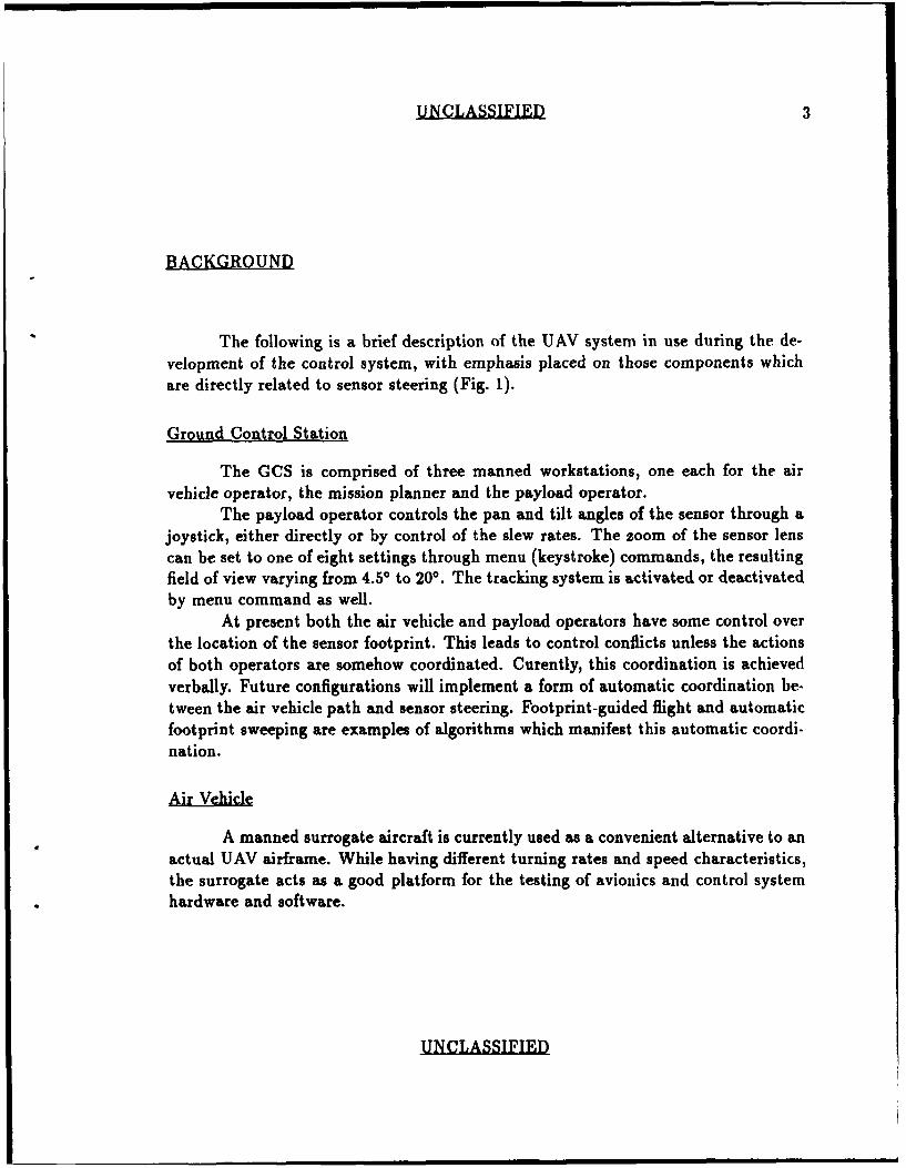
The following is a brief description of the UAV system in use during the de-velopment of the control system, with emphasis placed on those components whichare directly related to sensor steering (Fig. 1).
Ground Control Station
The GCS is comprised of three manned workstations, one each for the airvehicle operator, the mission planner and the payload operator.
The payload operator controls the pan and tilt angles of the sensor through ajoystick, either directly or by control of the slew rates. The zoom of the sensor lenscan be set to one of eight settings through menu (keystroke) commands, the resultingfield of view varying from 4.5* to 200. The tracking system is activated or deactivatedby menu command as well.
At present both the air vehicle and payload operators have some control overthe location of the sensor footprint. This leads to control conflicts unless the actionsof both operators are somehow coordinated. Curently, this coordination is achievedverbally. Future configurations will implement a form of automatic coordination be-tween the air vehicle path and sensor steering. Footprint-guided flight and automaticfootprint sweeping are examples of algorithms which manifest this automatic coordi-nation.
Air Vehicle
A manned surrogate aircraft is currently used as a convenient alternative to anactual UAV airframe. While having different turning rates and speed characteristics,the surrogate acts as a good platform for the testing of avionics and control systemhardware and software.
UNCLASSIFIED

UNCLASSIFIED 4
Command and Control System
The Pegasus autopilot [4] is bas( ' n an 8 bit micro'omputer operating at 1.2MHz; this is the only computing element present. It handles all of the computingtasks required by the UAV, such as AV stabilization in pitch and roll, telemetryencoding/decoding, sensor steering, engine control and navigation. All of the controllaws are updated at 30 Hz.
The primary sensors to the autopilot include a vertical gyro, a three-axis mag-netometer, static and dynamic pressure transducers.
Sensor Package
The sensor package consists of a shuttered B&W video camera with zoomlens attached to a mount having two degrees of freedom (Table I). As mentionedearlier, its maximum pan and tilt rates are not sufficient to maintain track while theAV is executing a sharp manoeuvre. In addition, the stringent rate and accelerationrequirements for stabilization necessitated the design of an improved mount, to bedescribed later in this report.
Travel Rate
Pan 3500 15 deg/sec
Tilt 100 ° 15 deg/sec
Table I: Mount Performance
Data Links
The uplink and downlink are both 9600 baud data streams consisting of 12 bitdata words; the uplink is composed of a 16 word frame repeating at 37.5 Hz, whilethe downlink is composed of a variable-size frame which allows for selectable updaterates ranging from 30 Hz to 0.5 Hz.
The position of the UAV is derived in the GCS from a complementary filter[5] which combines range and azimuth data from a tracking radar with speed andheading data from the UAV. An accurate estimate of the UAV's position is criticalfor accurate tracking as well as for targeting in general; this method provides datawhich is more precise than that which could be achieved by one method alone.
UNCLASSIFIED
UNCLASSIFIED 5
ALGORITHM
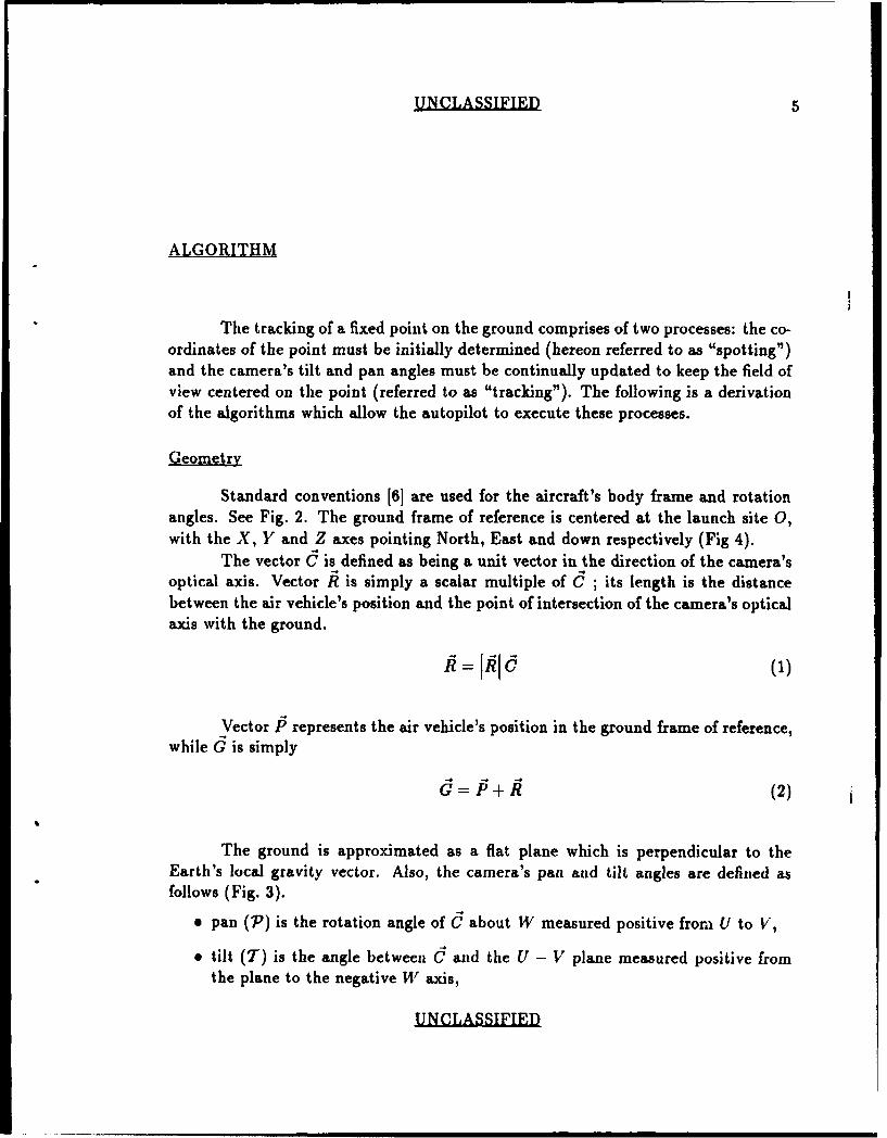
The tracking of a fixed point on the ground comprises of two processes: the co-ordinates of the point must be initially determined (hereon referred to as "spotting")and the camera's tilt and pan angles must be continually updated to keep the field ofview centered on the point (referred to as "tracking"). The following is a derivationof the algorithms which allow the autopilot to execute these processes.
Geometry
Standard conventions [6] are used for the aircraft's body frame and rotationangles. See Fig. 2. The ground frame of reference is centered at the launch site 0,with the X, Y and Z axes pointing North, East and down respectively (Fig 4).
The vector C is defined as being a unit vector in the direction of the camera'soptical axis. Vector .R is simply a scalar multiple of C ; its length is the distancebetween the air vehicle's position and the point of intersection of the camera's opticalaxis with the ground.
Vector P represents the air vehicle's position in the ground frame of reference,while d is simply
G=P±R (2)
The ground is approximated as a flat plane which is perpendicular to theEarth's local gravity vector. Also, the camera's pan and tilt angles are defined asfollows (Fig. 3).
@ pan (7') is the rotation angle of C about W measured positive from U to V,
* tilt (T) is the angle between d and the U - V plane measured positive fromthe plane to the negative W axis,
UNCLASSIFIED
UNCLASSIFIED 6
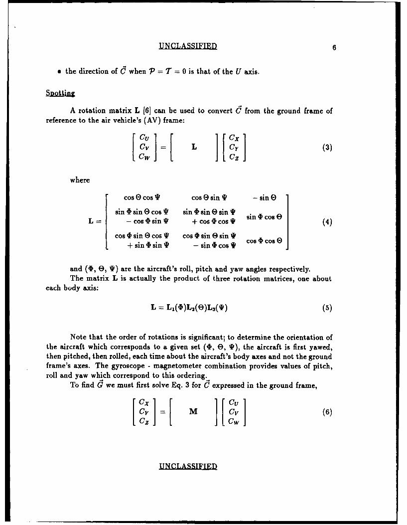
a the direction of d when P = T = 0 is that of the U axis.
A rotation matrix L [61 can be used to convert C from the ground frame ofreference to the air vehicle's (AV) frame:
I = L Cy (3)Cw Cz
where
cos 0 cos T cos O sin P -sinO
sin 4 sin 0 cos IF sin I sin ( sin I sL - cos O sin I + cos I cos I (4)
cos P sin 9 cos T cos I sin e sinT t+ sinI sin * - sin 4 cos oco
and (40, e, T) are the aircraft's roll, pitch and yaw angles respectively.The matrix L is actually the product of three rotation matrices, one about
each body axis:
L = L1($)L 2 (e)L3 (T) (5)
Note that the order of rotations is significant; to determine the orientation ofthe aircraft which corresponds to a given set (1, 0, T), the aircraft is first yawed,then pitched, then rolled, each time about the aircraft's body axes and not the groundframe's axes. The gyroscope - magnetometer combination provides values of pitch,roll and yaw which correspond to this ordering.,
To find G we must first solve Eq. 3 for C expressed in the ground frame,
CY CV (6)Cz Cw
UNCLASSIFIED

UNCLASSIFIED 7
where M is the inverse of L. Since L is a unitary matrix, its inverse is simplyits transpose:
sint sin cos I cos I sin 0 cos9-cos f sin*i + sin 4 sin
M = Cos 0 sin sin 4 sin 0 sin 1P cos I sin E sin (7)+ Cos I C os f - sin § cos T
-sin 0 sin I cos 0 cos I cos 0
For brevity, the entries of M will be abbreviated as follows:
a b c
M= d e f (8)
The vector C(AV) can be written in terms of the pan and tilt angles (Fig. 3).
[ E" = E T sin ] (9)CwI - sin T
Substituting Eq. 9 into Eq. 6 results in
Cx a(cosT cos P) + b(cos Tsin P) + c(- sinT)
C d(cos Tos P) + e(cosTsinP) + f(- sinT) (10)Cz I g(cos T cos P) + h(cos Tsin P) + i(- sinT) ]
From Eq. 1 one writes
RzCxRx= -- (11)
RzCy
R - Rz~y (12)
UNCLASSIFIED

UNCLASSIFIED 8
and from Eq. 2
Gx = Py + Rx
Gy = Py + Ry (13)
The spotting process is shown in Fig. 5. When evaluating the above equationsthe air vehicle's northings and eastings relative to the launch site 0 are used for PXand Py. The air vehicle's altitude is substituted for Rz, which is equal to Pz due tothe flat earth assumption.
Tracking
Eq. 11 can be expanded as follows:
Rx [g(cos T cos P) + h(cos T sin 7) - isinT] =
Rz [a(cos T cos P) + b(cos T sin P) - csin T] (14)
This can be rewritten as
tan T = cos 7 [Rxg - Rza] + sin 7 [Rx h - Rzb] (15)[Rxi - Rzc]
Likewise, Eq. 12 can be rewritten as
tan T = cos 7 [Ryg - RzA + sin 7' [Ryh - Rze] (16)[Ri- Rzf]
For brevity, Eq. 15 will be written as
A cos 7 + B sinP (17)tan T = 1)
C
and likewise for Eq. 16:
tanT = +Esin (18)F
UNCLASSIFIED

UNCLASSIFIED 9
By equating Eq. 17 and Eq. 18 we can write
7'=arctan - A) (19)
The final form of this equation has been written with only one division toaccommodate a rapid calculation by the autopilot. Once the pan angle has beencalculated by the above equation, the tilt angle can be found by returning to eitherEq. 17 or Eq. 18.
Solving the above equations results in two possible sets of (7, T): one whichcorresponds to 1?, the other which corresponds to -R. To determine the correctchoice, the component of R along the W axis is found.
If C is replaced with R in Eq. 3:
Rw = Rxc + Ryf + Rzi (20)
The decision as to which set to choose is made as follows:
1. if Rw is positive, choose the set with a negative tilt angle,
2. if Rw is negative, choose the set with a positive tilt angle. (As a positive tiltangle is physically impossible for the camera to realize, the tilt is in reality setto zero). This situation may conceivably arise if the target point is far fromthe aircraft and the aircraft is pitched or rolled in the direction of the targetpoint. The pan angle is nevertheless set correctly, which allows for a quickreacquisition once the target becomes "visible" again.
3. if Rw is close to zero, the choice as to which set to use would have to be basedon some other criteria. In this case R or -R is chosen according to 7; thatvector which results in a value of "P closest to the value computed during thelast update cycle is chosen.
Methods (i) and (ii) may produce incorrect results if T is small in magnitude:Rw will also be small in this case, and could potentially be of the wrong sign due tonoise or to the time lag of the overall system. Conversely, method (iii) may produceincorrect results if T is close to 900. In this case the rate of change of 7 can approachinfinity as C passes near this point, and a choice based on the smallest change of7 may be erroneous. For these reasons the threshold value of T used to determinewhich method is to be used can set arbitrarily to some value which is close to neither0° nor 900.
The tracking process is shown in Fig. 6.
UNCLASSIFIED

UNCLASSIFIED 10
IMPLEMENTATION
The above algorithms for spotting and tracking have been used in the writingof two sets of software; one includes the actual assembler code which is meant tobe integrated into the existing Pegasus software, along with test versions meant foremulation only. The other includes short PASCAL programs which aid in testingboth the validity of the algorithm and the more complex assembler code.
The remainder of this report describes the process of implementing this algo-rithm into our existing UAV system.
Speed Considerations
Due to the limited amount of processing power available in the autopilot, itwas necessary to update the tracking routine at 15Hz, instead of 30Hz as is the casewith the remainder of the functions executed.
The computations are performed in the large part with a 24 bit fixed pointnumerical format, allowing for very fast addition, subtraction and multiplication.In addition to the aforementioned, the only other operations required by the finalequations were those of division and arctangent, which were implemented as shownin the appendix. A listing of the execution times required by each operation whenrun on the Pegasus autopilot is shown in Table II.
Operation Execution Time
add / subtract 21.2 Asecmultiply 167.2 psecdivide 1.26 msecarctan 0.60 msec
Table II: Execution Times
UNCLASSIFIED

UNCLASSIFIED 11
Accuracy Considerations
The original performance goal was to achieve pointing accuracy within 10;while not overly stringent, this nevertheless required attention to certain error sourcesas listed below.
Numerical Format
As mentioned earlier, the computations are performed in a 24 bit fixed pointformat; this format represents a fractional value which varies from -1.0 to +1.0.Multiplications will therefore invariably produce results which have an accuracy whichis less than or equal to that of the multiplicands. To offset this trend, it is necessaryto shift the values, which is done only at certain locations in the software. This "semifloating point" operation is essentially a compromise between the accuracy of floatingpoint and the speed of fixed point operations.
A related problem was the evaluation of Eq. 17 or Eq. 18; both of thesewill approach the undefined value of 0/0 for certain aircraft and camera orientations.These equations do not both approach the singularity simultaneously, and the problemwas thus solved by allowing the software to chose the appropriate one when calculatingT.
Proper operation of the tracking system depends on the alignment of a subsetof the equipment onboard the AV, namely the magnetometer, the vertical gyroscopeand the camera mount. These devices can be thought of as each measuring a vector inspace (the local geomagnetic field, gravity and C respectively); these vectors must bemeasured in the same coordinate frame. If this cannot be easily accomplished throughthe construction of the mounting hardware, it can be done by rotating the data inthe autopilot software. This method is used in the case of the magnetometer, whichis mounted in the tip of a wing with a significant dihedral and sweep-back angle. Therotation angles needed were determined with precise surveying of the gyroscope andmagnetometer sites.
Note that the problem of wing flexure during flight had not been addressed.This flexure can be thought of as having two components: a fixed amount observedduring steady, level flight, and a variable component arising due to manoeuvres (bothbeing significant when using a surrogate aircraft). The rotation imparted to themagnetometer by the fixed component can in principle be deduced from data recordedduring flight. In practice this problem may not occur depending on the location ofthe magnetometer and on the type of aircraft used.
UNCLASSIFIED

UNCLASSIFIED 12
Sensor Errors
The specified performance of both the gyroscope and magnetometer used in-dicates that these sensors would not be the source of significant tracking errors.
The use of a static pressure transducer as an altimeter was originally intendedfor general flight control. In the case of tracking, the multiple inaccuracies inherentin this form of altimeter, some of which are listed below, can produce a significanttracking error:
e the temperature sensitivity of both the transducer and its reference voltage,
e local pressure changes at the static port due to the AV's aerodynamics,
* pressure changes due to changing meteorological conditions,
9 differences between the elevation of the UAV's launching point (the "flat earth"reference elevation) and that of G.
Some efforts were made to control the temperature sensitivity of the altimeter;other altimeter issues are discussed in the remainder of this report.
The positional errors inherent to the camera mount can be controlled duringits construction if attention is paid to the alignment of the pan and tilt axes, thealignment of the camera within the mount, the quality of the readout devices, etc.
Noise
To avoid gross errors in the estimate of R due to sporadic noise, an averagevalue is derived from multiple spottings. The number of spottings involves a trade-offbetween the noise-induced error and the error due to camera drift during the spottingseries.
The noise present on all of the many input signals to the tracking routinenecessitated the inclusion of filtering. First order pole filters (IIR) were applied tothe output of the track routine:
Y[n] = (1 - fi)Y[n - 11 + /X[n] (21)
where the time constant r is
-TT In(1-- ) (22)
UNCLASSIFIED

UNCLASSIFIED 13
Here T = 1/30 sec. and P = 1/8, resulting in a time constant of 0.25 sec.The time lag introduced by the large value of r is obviously a limiting factor in thetracking system's bandwidth. Reduction of the noise present on all input signalswould allow for a reduction in the amount of filtering in the tracking routine, whichin turn may increase the responsiveness of the overall system, depending on whichcomponent has the dominant time constant: filter, mount or otherwise.
An analysis of the sensitivity of the complete system to noise, both steady-state and time-varying, will not be presented here; suffice it to say the sensitivity isgenerally a non-linear function of a subset of the input values. Some of the moreimportant examples are listed below.
The tracking routine is most sensitive to noise in the following cases:
* When flying near G, the routine is sensitive to noise in all components of theestimate of the air vehicle's position (P).
* When flying directly above G or nearly so, the routine is sensitive to noise inthe estimation of the AV's northings and eastings (Px and Py), but only inthe calculation of ', which results in random image rotation. Nevertheless, theactual tracking accuracy is not affected.
The spotting routine is sensitive to noise in the estimates of both the airvehicle's attitude (1, E, %) and altitude (Pz) when either Rx or Ry are large incomparison to Rz.
I
UNCLASSIFIED

UNCLASSIFIED 14
TESTING
Bench Tests
The validity of the algorithm was first determined with simple simulations us-ing the PASCAL version. Here attention was paid to agreement between the spottingand tracking routines. The numerical accuracy of the assembly language version wasdetermined by comparing its results with that of the PASCAL version. Finally, theassembly language code was integrated into the Pegasus autopilot, which was testedwith simulated sensor data.
Flight Tests
The operation of the tracking system was observed to be essentially correctduring a seiies of flight trials. Nevertheless, the system was not used by GCS personnelduring Canadian Forces exercises in 1988 and 89, preferring instead the manual controlmode. The specific problems which were noted at the time include:
* The pointing accuracy was not sufficient to keep G in the field of view ( 4.50 )of the camera when high magnification was used. High magnification was usedby the payload operator when attempting to identify individual targets.
a Serious tracking errors would occur in the case of loss of air vehicle positiondata due to errors in the uplink telemetry.
e Difficulty was experienced by the payload operator when attempting to relocateG to another target. Once again this was done at high magnification, wherebythe small random motions of the air vehicle would cause large motions in theFoV. The tracking system was unable to compensate for these motions (withfrequencies above 2 Hz and amplitudes greater than 1).
Test Conclusions
The performance achieved by the tracking system was found to be very de-pendent on both i) the quality of the input data and ii) the ability of the sensor
UNCLASSIFIED

UNCLASSIFIED 15
mount to respond quickly to positioning commands. Both of these points are specificto the particular implementation, and as such are not due to the correctness of thealgorithm, nevertheless they must be addressed.
In addition, it may be possible to improve the usefulness of the tracking systemby modifying the algorithm such that user-commanded corrections can be appliedwithout the loss of stabilization.
Methods of improving i) and ii), as well as the modified tracking algorithmare discussed in the following chapter.
UNCLASSIFIED
UNCLASSIFIED 16
FUTURE WORK
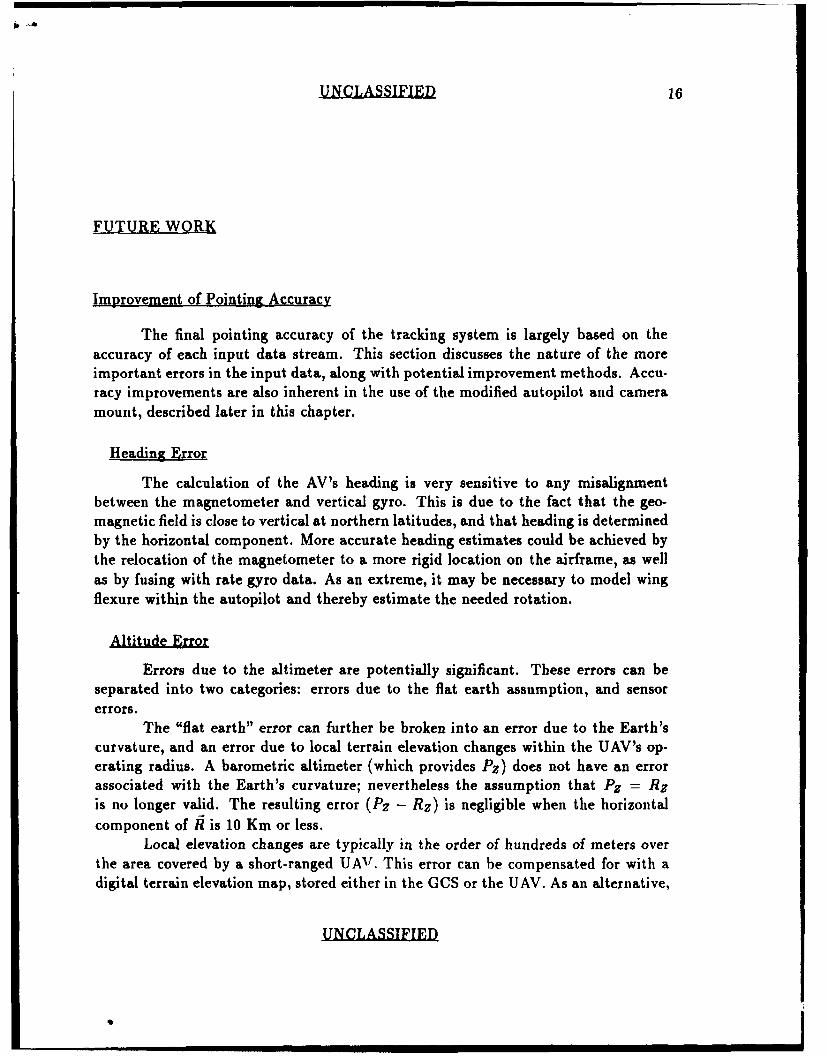
Improvement of Pointing Accuracy
The final pointing accuracy of the tracking system is largely based on theaccuracy of each input data stream. This section discusses the nature of the moreimportant errors in the input data, along with potential improvement methods. Accu-racy improvements are also inherent in the use of the modified autopilot and cameramount, described later in this chapter.
Heading Error
The calculation of the AV's heading is very sensitive to any misalignmentbetween the magnetometer and vertical gyro. This is due to the fact that the geo-magnetic field is close to vertical at northern latitudes, and that heading is determinedby the horizontal component. More accurate heading estimates could be achieved bythe relocation of the magnetometer to a more rigid location on the airframe, as wellas by fusing with rate gyro data. As an extreme, it may be necessary to model wingflexure within the autopilot and thereby estimate the needed rotation.
Errors due to the altimeter are potentially significant. These errors can beseparated into two categories: errors due to the flat earth assumption, and sensorerrors.
The "flat earth" error can further be broken into an error due to the Earth'scurvature, and an error due to local terrain elevation changes within the UAV's op-erating radius. A barometric altimeter (which provides PZ) does not have an errorassociated with the Earth's curvature; nevertheless the assumption that Pz = Rzis no longer valid. The resulting error (Pz - Rz) is negligible when the horizontalcomponent of / is 10 Km or less.
Local elevation changes are typically in the order of hundreds of meters overthe area covered by a short-ranged UAV. This error can be compensated for with adigital terrain elevation map, stored either in the GCS or the UAV. As an alternative,
UNCLASSIFIED
QI

UNCLASSIFIED 17
an active altimeter could be used, such as a radar altimeter or laser rangefinder. Inthe case of a radar altimeter or similar sensor, the altitude of the air vehicle over thelocal terrain would be known precisely, yet there would remain an unknown differencebetween the elevation of G and that of the terrain directly below the air vehicle (S).This error would tend to increase with the distance G - S. A laser rangefinder,mounted collinearly to the imaging sensor, would provide an accurate estimate ofeach component of fi. If the laser rangefinder was the only source of altitude data,it would be necessary to assume that tracking was precise, and that any changes in1191 were due changes in the AV's position. This could lead to an unstable trackingsystem.
If it is assumed that the barometric altimeter used is sufficiently accurate,weather-related changes in pressure become the primary sensor error for long durationflights. As with the magnetometer, it may be possible to improve the signal withcompensations, such as with barometric data measured at the GCS.
The best estimate of RZ would be obtained with a combination of sources,such as a radar altimeter used in conjunction with a terrain elevation map, or a laserrangefinder used with a barometric altimeter.
Air Vehicle Position and Attitude Error
As mentioned earlier, poor quality uplink can produce tracking errors, in thiscase by way of corrupted air vehicle position data. This and similar uplink problemscan be reduced with the use of an onboard model of the AV flight dynamics (essentiallya short term navigation system). The AV position as predicted by the model wouldbe used in the case that there is a large disagreement between it and the positiondata arriving on the uplink.
Work is currently underway at DRES to apply a differential Global PositioningSystem (DGPS) in a surveillance UAV [7]. Apart from benefits such as increasedAV range and autonomy, a DGPS system could provide navigation data includingaltitude, accurate to within 5 meters, which is an obvious improvement over thatavailable from tracking radars and our current altimeter. Work is also underway tointegrate a strapdown AHRS system into the avionics suite so as to achieve a moreprecise estimate of the AV's attitude.
Improved Camera Mount
The next flights will incorporate a modified camera mount. Its main improve-ments over the previous mount are:
e much improved slew rates in both axes (minimum 60 deg/sec),
UNCLASSIFIED
UNCLASSIFIED 18
" angular accelerations of 300 deg/sec2 ,
* continuous 3600 travel in pan,
" precise construction necessary to ensure proper alignment,
" accurate position encoders,
" the potential for conversion to fully digital control.
An overall betterment in the tracking accuracy should result, as well as im-proved stabilization. This mount is in the prototype stage and will require test flightsto ascertain its full usefulness.
regasus IB Autopilot
A modified version of the Pegasus autopilot is currently being developed toaddress the limitations of memory and computation capabilities which were encoun-tered during the development of the tracking algorithm' These modifications resultin:
" an increase in clock speed from 1.22 to 1.852 MHz, improvirlg computationalspeed by over 50 %,
" increased RAM (8 Kbytes) and EPROM (64 Kbytes),
* an improved stable reference voltage for use with the altimeter.
New Algorithm
It has been noted that the payload operator experiences difficulty when re-positioning the camera from one ground point to another, mainly due to the lack ofany stabilization during this transitic , A-s a result it would be desirable to implementan algorithm which provides stab;* ,ion continuously, and not only during trackingmode as has been the case. A - ,sible solution is outlined below:
1. Upon entry into the stabilization mode, use 1P, T and (1, E, P) to produce aunit vector C with respect to the ground frame of reference.
2. Use the pan command to modify the azimuth of C in the ground FoR; likewiseuse the tilt command to modify the elevation of C. The commanded valueswill be derived from the summation of two weighed components, one from thejoystick and the other from the tracking algorithm (if selected).
UN CLASSIFIED

UNCLASSIFIED 19
3. Use the newly modified C, as well as the present ( T, , ') to produce the panand tilt positioning commands for the camera mount.
4. Repeat (ii) through (iv).
This method involves the interpretation of joystick commands as movementsin the ground FoR instead of in the air vehicle FoR as before, which may prove moreintuitive to the payload operator. Secondly, the joystick commands can be thoughtof as corrections to the location of G; this would give the payload operator the abilityto select multiple targets in quick succession while retaining the benefits of tracking.
UNCLASSIFIED

UNCLASSIFIED 20
SUMMARY
An algorithm has been developed which allows for the automatic tracking of afixed ground point using our existing avionics suite and video camera payload. Thisalgorithm has been implemented in the Pegasus autopilot and tested during severalflights aboard a surrogate UAV. While the basic operation of the tracking mode wasobserved to be correct, the poor precision and speed of the system resulted in limitedusefulness. These problems will be addressed in the short term with an improvedcamera mount and autopilot, and in the long term with advanced navigation systemssuch as the Global Positioning System.
UNCLASSIFIED

UNCLASSIFIED 21
BIBLIOGRAPHY
[11 Weiler, D.R., Juneau, Capt. J.A.F.J., et al, "RPV Concept Evaluation - RPVsin RV 85 (U)", Suffield Memorandum 1156, February 1986. UNCLASSIFIED
[21 Chesney, R.H. and Henders, M.G., "Operational Tests of RPVs in Exercise RV87 (U)", Sufield Report 502, August 1988. UNCLASSIFIED
13] Amick, G.S., "Unmanned Air Vehicles Payloads and Sensors", Lockheed Missles& Space Company, Inc., Lockheed Austin Division, Austin Texas, presented atthe AGARD Guidance and Control Symposium, San Francisco, October 1988.
[4] Burton, S.K. and Weiler, D.R., "The Pegasus Autopilot for Remotely PilotedVehicles (U)", Suffield Memorandum No. 1167, April 1986. UNCLASSIFIED.
[5] Aitken, V., "A Complementary Tracking Filter for Remotely Piloted Aircraft(U)", Suffield Memorandum No. 1292, June 1989. UNCLASSIFIED.
[6] Etkin, B., Dynamics of Atmospheric Flight, John Wiley & Sons, Inc., New York,1972, Chapter 4.
[7] Ollevier, T.E., private communication.
I
UNCLASSIFIED
| | |

UNCLASSIFIED A-1
APPENDIX A
ARCTAN is implemented as the reverse look-up of a tangent table; a directlook-up of an arctangent table would not have been feasible as the high non-linearity of the function would have caused a loss of resolution in the table forsmall angles.
DIVX is implemented as two 16 bit integer divisions which, although not asprecise as a full 24 bit division, is much faster, due in great part to a 16 bittransfer instruction available to the 63701 microcomputer. The first division isquotient/divisor, which produces a remainder, the second is remainder/divisor.
Some further clarification is required to explain the two following operations:
- The 24 bit format is generally used to represent a signed fractional valuewhich varies from -1.0 to +1.0 - c, where c = 2-2 3 .
- This value may include an implied exponent which is some power of 2,depending on its use in the program.
- To produce an output which is precise to within 0.50, the arctangent func-tion need only accept arguments with a magnitude less than 127; argu-ments with implied exponents of 26 are thus properly formatted for thisfunction, being that they will have the greatest possible resolution whileencompassing the necessary range.
- The result of a division is always used as the argument for an arctangent,hence its result should have an implied exponent of 26.
UNCLASSIFIED
immmmm mm mm mmmmlmlmmmmmm llm

UNCLASSIFIED A-2
* DIVX
* THIS PROGRAM IS A DOUBLE 16-BIT DIVIDE* WHICH PRODUCES A 16-BIT RESULT. THIS RESULT* IS BOTH SHIFTED RIGHT 8 TIMES AND LIMITED* TO A VALUE OF 7F (127).
* syntax such as " value -> C " denotes the contents of a register,
* while " (value) -> C " also implies that the contents happen to* be inconsequential to the program.
LINEO BYE SKIPi is the divisor = 0 ?LDAA #OFFHSTAA DIVFLG yen, sent error flag and return.RTS
SKIPI CLR DIVFLG no, clear the error flag.CLR SIGN SIGN records the sign of the quotient.
TSTA is the divisor negative ?BPL LINEA if so, negate both the divisorCOMA and the sign flag.
COMB
ADDD #1
COx SIGN
LINE& STD DIVISORLDD VCCBPL LINEB is the dividend negative ?
COMA if so, negate both the dividend
COMB and the sign flag.
ADDD #1
COM SIGNLINEB JSR BROLLS do a 16 bit divide, V.ACC / DIVISOR.
TSTA
BPL LINES
ADDD DIVISOR adjust remainder (step 2, p. 267).
* this section limits the absolute value of the result to 7F (127);* i.e. a quotient greater than 127 is considered to be approx. 127.
LINES IGDI quot. -> D rem. -> X
UNCLASSIFIED

UNCLASSIFIED A-3
TSTIBEQ SKIP2 are 8 m.s. bits of quotient - 0 ?TST SIGN no, should the result be positive ?BPL LINECLDD #8000H no, sot V1ACC to -1.BRA LINED
LINEC LDD #7FFFH yes, set V.1CC to +1.LIKED STD V.1CC
CLR VACC+2RTS return to main program.
SKIP2 STAB V.1CC yes; store the 8 1.s. bits of the* quotient into V.1CC.
• this section shifts the remainder up by either 8 or 4 or not at• all, whichever is the highest possible. It then shifts the* divisor accordingly until it has boon shifted 8 bits down w.r.t• the remainder.
*************** *** ******* *** * *** ******** ******* ***********
1GDI (quot). -> I rem. -> D
BITA #OFOH can the remainder be shifted up by 4 '
BIE LINE6 no; ( shift divisor down 8 ).ASLD yes; shift 4.ASLDASLDASLDBITA tOFON can the remainder be shifted up again ?BNE LINE? no; ( shift the divisor down4 ).ASLD yes; shift 4 a second time.ASLDASLDASLDJSR BROLLS divide the remainder by DIVISOR.BRA LINE8
LINE6 IGDI (quot.) -> D rem. -> I (store rem.)LDD DIVISORLSRDLSRDLSRD shift divisor down 8,LSRDLSRDLSRD
UNCLASSIFIED

UNCLASSIFIED A-4
LSRD
LSRDADDD #i and round up.STD DIVISOR
XGDX (quot.) -> I rem. -> DJSR B_ROLLS divide the remainder by DIVISOR.
BRA LINE8
LIIE7 IGDI (quot.) -> D rem. -> I (store rem.)LDD DIVISOR
LSRD
LSRD shift divisor down 4,
LSRD
LSRD
ADDD #1 and round up.
STD DIVISOR
IGDI (quot.) -> I rem. -> DJSR BROLLS divide the remainder by DIVISOR.
LINE8 IGDI quot. -> D (rem.) -> ISTAB VACC+1 store 8 l.s. bits of the quotient
* into V-.CC+i. Note that the 8 m.s.
* bits will always be 0 in this case.
TST SIGN should the final result be negative ?BPL LINE9LDD V_.CCCOMA
COMB
ADDD #1
STD VACC yes; negate VACC, V_.CC+i.
LINE9 CLR VACC+2 always clesr VACC+2.
RTS
* the barrel roll subroutine assumes that the dividend is in* the D accumulator and divisor is in DIVISOR. It returns the
* quotient in the I register and the remainder in the D register.* See Computer Organization (McGraw Hill) p. 267 for details on
* the non-restoring integer division algorithm.
B_ROLLS IGDI dividend -> I (Q)
LDAA #16
STLA COUNT initialize count to 16 ( : # of bits).CLRA
UNCLASSIFIED

UNCLASSIFIED A-5
CLRB clear D register. (A)
LOOP TSTA is "A" positive ?BRI LINEI
XGDX yes; A -> I ->D
ASLD shift QXGDX A -> D q->I
ROLBROLA shift A
SUBD DIVISOR subtract M
BRA LINE2LINE1 XGDX no; A -> I Q ->D
ASLD shift QXGDX A -> D Q ->IROLB
BOLA shift AADDD DIVISOR add M
LINE2 TSTA is A positive ?BRI LINE3 yes;1GDX
ORAB #01H get Qo to 1.
ZGDXBRA LINE4
LINE3 XGDX no;AIDB lOFEH set Qo to 0.XGDX
LINE4 DEC COUNT decrement count.
BIE LOOP loop back.RTS
* ARCTAX
* ARCTAN IS A REVERSE LOOK-UP OF TAN TBL.
* IT RETURNS Al ANGLE BETWEEN -PI/2 AND* +PI/2, EXPRESSED If lADS/8. THE ARGUMENT
* OF THIS MACRO IS UNDERSTOOD AS HAVING AN* EXPONENT OF 2^8.
ATl LDD VACC
STD TAN
UNCLASSIFIED

UNCLASSIFIED A-6
BKI TN-.Q4BSR ITAO
RTSTN-0Q4 COMA
COMBADDD #1STD TINBSR ATANLDD V..ACCCOMACOMBADDD *1STD V-.ACCRTS
ATAN LDX #TAN-TBLSTX TN-.LASTXCLR RESULTLDAB #80H
ATANI STAB DELTAABI
ABILDAA TANCIPA OX1
BLO ATAN3RIi ATA12
PSEALDAA TAN+1CMPA 1.1PULABLO ATAN3
ITA12 STI TL-LASTXADDB RESULTSTAB RESULTBRA ATAJ4
ATAN3 LDX TN..LASTXATAN4 LDAB DELTA
LSRBBEQ DONE-ATIBRA ATAl
DONE..ATI LDAA RESULTCLRB
UNCLASSIFIEID

UNCQLASSTFTED A-7
LSRDLSRDSTD V-.ACCNULl P3927CSRTS
TAL-TBL 7DB 0000B,0001H,0002H,0002HD0003H,0004,00051110006HFDB 0006H,0007E.0008H,0009H,0009I,000AI,000BH.000CHFDB OOODH,OOODH,OOOEN,OOOFH,OOI*B0011B,0011B,00121FDB 00131,O~iH,0015H ,00151 ,0061 OT,071O181 ,001917DB 00191,00111O00iBH,001CH,OO1DHOOIEH,001E1,00171FDB 0020100O21H0022H,00231,0023H, 00241.0025H,0026H7DB 0027H,0028HD0029H,0029H,002LH,002B1.002C1. OO2DHFDB 002E1,002F1.0030H,00301.0031H,0032H,00331.0034K7DB 00351,0036H0037 1 003809009O3AIIO3B.OO3CHFDB 003D1, 003E1,003EH,003F1,00401,00411,0042H.0043HFDB 0044H,00451,00461,0047H,0049HOO4AHOO4BH,004C1FDB 004D1,004E1,004F1,0050H,0051H,00521,0053H,00541FDB 0056H,00571.008,009H A.05&BOOBH,OQ5DH.005E
7DB 00571,00601,0061i00O63,OOOIE0065H,0066H,00681
FDB 0069H,006A1, OOCH,006D1,006E1, 00701,00711.007317DB 0074H,00751,00771,00781,007A1,OO7BH,007D1,007E17DB 0080H,0082H,00831.008N0086H0088,08A,OOBHFDB OODR008SF10091,00931,00941,00961,00981,009A1FDB 009C1,OO9EHOOAOH,00A21.0014HOOA6HOOA8H,OOAAH7DB 001DB. OOAF1, OOB1H,00B31,0OBGI00OB81,OOBBB,OOBDBFDB OOCOR,00C2HOOCBH ,00C71,OOCAE,OOCDBOODOI, 00D317DB 00D61,00D91,OODC1,O0DFH,0012H,00161,00E91,0OECHFDB OOEF.0073HOOF7H,007AE,OOFEH,0102H,0106HP010AHFDB OIOFI, 0113H, 01171 ,011C1, 121H,0126H,012B1, 01301FDB 0135K,013kK,0140K,01461,014C1,0152K,0158K016FKFDB 01661016GDH,01741,017CE,0183HO1BCH,0194101i9DHFDB 01A61,01AF1,01B91,01C41.01CFN,O1DAI,01E61,0172H7DB 01F,020DH,021B1,022A1,023A1, 024B3H025D1,026FHFDB 0283H.02991,02A7H,02C810O2E21,02FE1.031CH,033CHFDB 035F1,0385H,03kUB,O3DCH,040E1104451,04821,04C717DB 0514H,056B1. OSCEI,06411,06C71,0766B,0823,O9CHFDB OA2DB, OBA21, 0D931OBI, 145E1, 1B291,28BE1,517C1
UNCLASSIFIED

UNCLASSIFIED S M 1321
Iz
0
C,
uJJ
z rzzLuI-
UNCLASIFIE

UNCLASSIFIED S M 1321
z0
-00
z
4C0
U.0
0
UNCLASSIFIED

UNCLASSIFIED S M 1321
tu(1)NIS
0z iru
0
p z
P uJ
' 0
u
UNCLASSIFIED

UNCLASSIFIED S M 1321
0 --0w
uu j
0 0i
cc 00 0
z N
UNCLASSIFIED

UNCLASSIFIED S M 1321
)00
0 a Z 0 0
C 0 0~ ]
0 C0
z 0D
0 U.
0U 0
0
T--
LJ 0cb C,
U 0
0 h02
UNCLASIFIE

UNCLASSIFIED SM 1321
I
C.-- ° IZ &+
040
Zw
LL 0
-Im (A P
0 <0
0 0
00
co CC)
N o C-,I AIz 4 MccD
cc 2
N Uw <- 0
LU 0
0 CL
0 L02icCD -J7
(L 4 4
CDC
UNCLASSIFIED

UNCLASSIFIEDSECURITY CLASSIFICATION OF FORM
(highest classification of Title. Abstract. Keywords)
DOCUMENT CONTROL DATA(Security classificetion of title, body of abstract and Indexing annotation must be entered when the overall document is classified)
1. ORIGINATOR (the name and address of the organization preparing the document 2. SECURITY CLASSIFICATIONOrganizations for whom the document was prepared. e.g. Establishment sponsoring (overall security classification of the documenta contractor s report. or tasking agency, are entered in section .)including special warning terms if applicable)
Unclassified
3. TITLE (the complete document title as indicated on the title page. Its classification should be indicated by the appropriateabbreviation (SC,R or U) in parentheses after the title.)
A Sensor Stabilization/Tracking System For Unmanned Air vehicles (U)
4. AUTHORS (Lost name, first name. middle initial. If military, show rank, e.g. Doe, Maj. John E.)
Decruyenaere, Jean-Paul R.
5. DATE OF PUBLICATION (month and year of publication of 6a. NO. OF PAGES (total 6b. NO. OF REFS (total cited indocument) containing information. Include document)
May 1990 Annexes, Appendices, etc.)
6. DESCRIPTIVE NOTES (the category of the document, e.g. technical report, technical note or memorandum. If appropriate, enter the type ofreport, e.g. interim, progress, summary, annual or final. Give the inclusive dates when a specific reporting period is covered.)
8. SPONSORING ACTIVITY (the name of the department project office or laboratory sponsoring the research and development. Include theaddress.)
9a. PROJECT OR GRANT NO. (if appropriate, the applicable research 9b. CONTRACT NO. (if appropriate, the applicable number underand development project or grant number under which the document which the document was written)was written. Please specify whether prolect or grant)
10a ORIGINATOR'S DOCUMENT NUMBER (the official document 10b. OTHER DOCUMENT NOS. (Any other numbers which maynumber by which the document is identified by the originating be assigned this document either by the originator or by theactivity. This number must be unique to this document.) sponsor)
1 1. DOCUMENT AVAILABILITY (any limitations on further dissemination of the document, other than those imposed by security classification)
X) Unlimited distributionI Distribution limited to defence departments and defence contractors; further distribution only as approved
I ) Distribution limited to defence departments and Canadan defence contractors: further distribution only as approvedI Distribution limited to government departments and agencies; further distribution only as approved) Distribution limited to defence departments; further distribution only as approved
I ) Other (please specify):
1 2. DOCUMENT ANNOUNCEMENT (any limitation to the bibliographic announcement of this document This will normally correspond tothe Document Availabilty 111). However. where further distribution (beyond the audience specified in 11) is possible. a widerannouncement audience may be selected.)
Unlimited
tINT.ARRIFT Ef
SECURITY CLASSIFICATION OF FORM
SECU1RITV CLASSIFICATION OF FORMJ
13. ABSTRACT Ia brief and faOuW swmuwy of thes documois It meay else appear elsewhere in t bodo of the document itself. It is highlydesirable that the abstract of classified documentst be uncsidfiedl. Each poayapt of the abstract shall begin with an indcation of tsecurity classification of thet informetw n t p- -pool, (ims die document itself is unclassified) represented as (S). (C). (111, or (U.it is not necessary to include here abstracts in be*h offIicali languages unless the text is bilinguall).
A control algorithm for the automatic steering of an imaging sensor hasbeen developed at DRES. Both the tracking of a fixed ground point arnd thestabilization of the sensor are addressed. This system has been implemented inlarge part with pre-existing hardware and software in our UAV system. This
veport describes the theoretical basis of the system as well as detailing thei:33:iue5 concerning the development of a working prototype.
14. KEYWORDS. DESCRIPTORS or ITIFIERS ftechnicelly meeaniogful terms or short phrases tha characterIte a document and could behelpful in cataloguing the documen They should be selected so that no security classification is required. Identifiers, such as equipment
J esignation. trade name, military project: code name. geographic location may also be included. If possible keywords should be selected-c- a published thesaurus. e.g. Thesaurus of Engineermil endf Scientific Terms (TST) andl that tearsinife.If is is not possible to
.e:ect indexing terms which wre Unclassified, t classification of each should be indicated as with the title.)
UAV
algor'ithm
tracking RPVJ ~~fZ.
UNCLASSIPIEDSECURITY CLASIICATIO Of FORM