universal avr controller · connector k2 exposes port a of the microcontroller. pins 1 and 2 are...
TRANSCRIPT

Universal AVR ControllerBoard
User Manual
May 2012

AxiTimer
Table of Contents1 Features 4
2 Technical Specifications 4
3 Interfacing 5Board Overview 5USB - POWER Connector (K1) 6
Power Supply 6USB Connection 6
PA Connector (K2) 7PC Connector (K3) 7PD Connector (K4) 8PWM 01-08 Connector (K5) 8PWM 09-16 Connector (K6) 9PWM 17-24 Connector (K7) 9PWM 25-32 Connector (K8) 10SPI-PRG Connector (K9) 10
SPI 11Serial Programming Interface 11
4 I2C Bus 11Slave Addresses 11Role of the Microcontroller 11External I2C Bus 11
5 Reset 12Power Up 12Reset Button 12FT232R 12SPI-PRG Connector 12
6 Analog Inputs 12
7 USB-Serial Interface 14
8 Real-time Clock 14
9 Temperature Sensor 14
10 LED Drivers 15
11 Default Configuration 15Firmware 15
2 User Manual

AxiTimer
Jumpers 15
12 Arduino 16
13 Disclaimer 16
14 Contact Information 16
Revision HistoryDate Authors Description
2012-05-31 Peter S'heeren Initial release.
User Manual 3

AxiTimer
1 Features Atmel ATmega1284P microcontroller
clocked at 16 MHz.
USB 2.0 Full-Speed serial interface.
2 LED drivers provide 32 pulse-width modulation (PWM) output channels.
2 audio input channels with switched-capacitor filters and trimmers for manual adjustment.
Ultra high accuracy digital temperature sensor.
Battery backed up real-time clock.
Expandable I2C bus.
2 USARTs.
24 general-purpose multifunctional I/O channels.
Arduino compatible.
Jumpers allow for configuration of various parts on the board.
2 Technical Specifications
Power supply 8..12V DC
Power consumption Approx. 85 mA
Dimensions 102 mm x 68 mm x 13 mm (W x D x H)
Weight 38 g (without battery)
RTC backup power 10 years
4 User Manual

AxiTimer
3 Interfacing
Board Overview
Mark Label Description
1 K1 / USB - POWER USB and power connector
2 K2 / PA ATmega644 pins A0-A7 connector
3 K3 / PC ATmega644 pins C0-C7 connector
4 K4 / PD ATmega644 pins D0-D7 connector
5 K5 / PWM 01-08 PCA9635 LED driver #1 pins LED0-LED7 connector
6 K6 / PWM 09-16 PCA9635 LED driver #1 pins LED8-LED15 connector
7 K7 / PWM 17-24 PCA9635 LED driver #2 pins LED0-LED7 connector
8 K8 / PWM 25-32 PCA9635 LED driver #2 pins LED8-LED15 connector
9 P1 Trimmer for adjusting the reference voltage of the A/D converter in the microcontroller (see microcontroller pin AREF)
10 P2 Trimmer for adjusting the volume of audio input channel #1
11 P3 Trimmer for adjusting the volume of audio input channel #2
12 K9 / SPI-PRG SPI-PRG connector
13 B1 RTC backup power battery, 3 V type CR2032
14 S1 Reset button
User Manual 5
1312
95 6 7 8
1 2 3 410 11
14

AxiTimer
USB - POWER Connector (K1)
Mark Description
1 GND
2 USB D+
3 GND
4 USB D-
5 USB VCC
6 3.3 V output
7 GND
8 N.C.
9 GND
10 8..12 V DC input
1
2
3
4
5
6 8 10
7 9
2 4 6 8 10
GND pins 1, 3, 7, and 9 are wired together.
Power Supply
Connect the 8..12V DC source to pin 10.
Connect the ground to one of the GND pins.
USB Connection
The board incorporates an FTDI FT232R USB-serial interface chip.
The serial interface of the FT232R is TTL. Pin DTR of the FT232R is connected to the reset circuit of the microcontroller, pins TXD and RXD are connected to the microcontroller pins PD0/RXD0 and PD1/RXD1 respectively. From a software viewpoint, the FT232R is connected to USART0.
The USB interface of the FT232R is Full-Speed (12 MHz) USB 2.0 compatible. Pins USBDP, USBDM, RESET, and 3V3OUT of the FT232R connect to K1's pins 2, 4, 5 and 6 respectively.
When mounting a USB B receptacle to K1, one must consider the proper wiring of the shield. The circuit depicted to the right provides the recommended connection between the shield of the USB B receptacle and the board's ground.
The capacitor must have a working voltage of 1000 V.
6 User Manual

AxiTimer
PA Connector (K2)
Mark Description
1 Microcontroller pin PA0[1]
2 Microcontroller pin PA1[2]
3 Microcontroller pin PA2
4 Microcontroller pin PA3
5 Microcontroller pin PA4
6 Microcontroller pin PA5
7 Microcontroller pin PA6
8 Microcontroller pin PA7
9 5 V
10 GND[1] J2 determines connection with PA0.[2] J3 determines connection with PA1.
1
2
3
4
5
6 8 10
7 9
2 4 6 8 10
Connector K2 exposes port A of the microcontroller.
Pins 1 and 2 are used in conjunction with the analog input circuits.
PC Connector (K3)
Mark Description
1 Microcontroller pin PC0
2 Microcontroller pin PC1
3 Microcontroller pin PC2
4 Microcontroller pin PC3
5 Microcontroller pin PC4
6 Microcontroller pin PC5
7 Microcontroller pin PC6
8 Microcontroller pin PC7
9 5 V
10 GND
1
2
3
4
5
6 8 10
7 9
2 4 6 8 10
Connector K3 exposes port C of the microcontroller.
Pins 1 and 2 provide the connection point for an external I2C bus.
User Manual 7

AxiTimer
PD Connector (K4)
Mark Description
1 Microcontroller pin PD0
2 Microcontroller pin PD1
3 Microcontroller pin PD2
4 Microcontroller pin PD3
5 Microcontroller pin PD4
6 Microcontroller pin PD5
7 Microcontroller pin PD6
8 Microcontroller pin PD7
9 5 V
10 GND
1
2
3
4
5
6 8 10
7 9
2 4 6 8 10
Connector K4 exposes port D of the microcontroller.
Pins 1 and 2 provide the connection point with USART0 of the microcontroller. These pins are also connected with the FT232R when jumpers J8 and J9 are closed.
Pins 3 and 4 provide the connection point with USART1 of the microcontroller.
PWM 01-08 Connector (K5)
Mark Description
1 LED driver #1 pin LED0
2 LED driver #1 pin LED1
3 LED driver #1 pin LED2
4 LED driver #1 pin LED3
5 LED driver #1 pin LED4
6 LED driver #1 pin LED5
7 LED driver #1 pin LED6
8 LED driver #1 pin LED7
9 5 V
10 GND
1
2
3
4
5
6 8 10
7 9
2 4 6 8 10
Connector K5 exposes the first eight LED outputs of LED driver #1.
8 User Manual

AxiTimer
PWM 09-16 Connector (K6)
Mark Description
1 LED driver #1 pin LED8
2 LED driver #1 pin LED9
3 LED driver #1 pin LED10
4 LED driver #1 pin LED11
5 LED driver #1 pin LED12
6 LED driver #1 pin LED13
7 LED driver #1 pin LED14
8 LED driver #1 pin LED15
9 5 V
10 GND
1
2
3
4
5
6 8 10
7 9
2 4 6 8 10
Connector K6 exposes the last eight LED outputs of LED driver #1.
PWM 17-24 Connector (K7)
Mark Description
1 LED driver #2 pin LED0
2 LED driver #2 pin LED1
3 LED driver #2 pin LED2
4 LED driver #2 pin LED3
5 LED driver #2 pin LED4
6 LED driver #2 pin LED5
7 LED driver #2 pin LED6
8 LED driver #2 pin LED7
9 5 V
10 GND
1
2
3
4
5
6 8 10
7 9
2 4 6 8 10
Connector K7 exposes the first eight LED outputs of LED driver #2.
User Manual 9

AxiTimer
PWM 25-32 Connector (K8)
Mark Description
1 LED driver #2 pin LED8
2 LED driver #2 pin LED9
3 LED driver #2 pin LED10
4 LED driver #2 pin LED11
5 LED driver #2 pin LED12
6 LED driver #2 pin LED13
7 LED driver #2 pin LED14
8 LED driver #2 pin LED15
9 5 V
10 GND
1
2
3
4
5
6 8 10
7 9
2 4 6 8 10
Connector K8 exposes the last eight LED outputs of LED driver #2.
SPI-PRG Connector (K9)
Mark Description
1 MOSI
2 VCC
3 SS
4 N.C.
5 RESET
6 N.C.
7 SCK
8 N.C.
9 MISO
10 GND
11 Polarity notch
910
1
57
3
6
2
8
4
11
Connector K9 provides a connection point to the SPI and the serial programming interface of the microcontroller. Only one of these interfaces can be used at a given time.
10 User Manual

AxiTimer
SPI
Pins 1, 3, 7, 9 and 10 provide a complete SPI bus. Pin 2 provides 5 V DC.
Serial Programming Interface
Pins 1, 5, 7, 9 and 10 provide the serial programming interface. Pin 2 provides 5 V DC.
4 I2C Bus
Slave AddressesThe I2C bus on the board interconnects the microcontroller with a set of I2C slave devices. Each slave device responds to one or more I2C addresses. The addresses are:
Address Slave Device
1001000b SE95 temperature sensor
1010001b PCF2129A real-time clock
0001000b PCA9635 LED driver #1
0001001b PCA9635 LED driver #2
1110000b PCA9635 all devices "LED All Call" address
0000011b PCA9635 all devices SWRST (software reset)
Role of the MicrocontrollerThe microcontroller can act as an I2C master, an I2C slave, or both. The microcontroller's two-wire serial interface is capable of both master and slave operations.
When the microcontroller is programmed to perform only as an I2C slave device, then there will be no I2C master present on the board. To take advantage of the I2C bus, an external I2C bus with at least one I2C master will have to be connected to the board.
External I2C BusThe I2C bus can be expanded with an external I2C bus. Pins 1 and 2 of connector K3 provide the connection point for an external I2C bus. These pins are connected to the 5 V supply using 10 kΩ pull-up resistors.
User Manual 11

AxiTimer
5 Reset
Power UpDuring a power up, the PCF2129A real-time clock will reset if no battery is present. All other chips will reset.
Refer to the corresponding datasheets for information about the initial state of the various chips.
Reset ButtonPressing the reset button (S1) will trigger a reset of the microcontroller. When the reset button is released, the microcontroller will leave the reset state and start executing the software.
FT232RThe DTR pin of the FT232R is connected to the reset circuit when jumper J10 2-3 is closed. A transition from logical one to logical zero of DTR will trigger a reset of the microncontroller.
SPI-PRG ConnectorPin RESET on the SPI-PRG connector (K9) is directly connected to the RESET pin on the microcontroller. A serial programmer will drive the RESET pin while performing its tasks.
6 Analog InputsThe board features two analog input circuits. Each circuit implements a MAX293CSA+ chip and a trimmer for adjusting the input volume.
Microcontroller pins PA0/ADC0 and PA1/ADC1 are assigned as the analog inputs. Jumpers allow to include or bypass each analog input circuit in the corresponding analog path.
Analog input circuit #1:
J2 J4 J5 Analog path
open closed closed K2 pin 1 analog input circuit microcontroller pin PA0/ADC0.
closed open open K2 pin 1 microcontroller pin PA0/ADC0.
Analog input circuit #2:
J3 J6 J7 Analog path
open closed closed K2 pin 2 analog input circuit microcontroller pin PA1/ADC1.
closed open open K2 pin 2 microcontroller pin PA1/ADC1.
The MAX293CSA+ chips require a clock signal for proper operation. The clock inputs of these chips are connected to pin PB3/OC0A of the microcontroller. Output OC0A is part of
12 User Manual

AxiTimer
timer/counter 0. Software must provide the clock signal when the analog inputs are required.
The cut-off frequency of the filter in the MAX293CSA+ is 1/100th of the provided clock signal frequency.
The following piece of AVR-GCC C code programs timer/counter 0 to generate a 1 MHz waveform:
// Settings: // - WGM[2..0]=010b: CTC mode, OCR0A defines the top value, no PWM // - COM0A[1..0]=01b: Toggle OC0A on Compare Match // - COM0B[1..0]=00b: Normal port operation, OC0B disconnected // - CS0[2..0]=001b: No prescaling hence 16 MHz -> enables the timer/counter // - OCR0A=16/2-1=7: Toggle at 2 MHz hence generating a 1 MHz block signal
DDRB |= 0b00001000; // OC0A: Set direction of pin PB3 to output OCR0A = 7; TCCR0A = 0b01000010; TCCR0B = 0b00000001; // Last step: enable the timer/counter
If you're running your software from the Arduino environment, keep in mind Arduino allocates timer/counter 0 for millisecond delay functions. The Arduino run-time sets up timer/counter 0 differently from the C code above. If you want to execute the C code, then you'll have to first stop timer/counter 0 as follows:
TCCR0B = 0b00000000; // Disables the timer/counter. TCCR0A = 0b00000000; // Set to zero before reprogramming TC0. If not, // the timer/counter will behave unpredictably.
After this, timer/counter 0 can be set up using the C code above.
Jumper J1 offers options for adjusting the voltage on the microcontroller AREF pin:
J1 1-2 J1 2-3 Description
closed open AREF input voltage is adjustable from 1.6 V to 3.2 V using P1.
open closed AREF input voltage is 5 V.
The first settings allows one to specify an AREF input voltage of around 2.5 V. As such the microcontroller's ADC function will produce signed integer values when sampling the analog input signal (0..5 V). This setting is intended for sampling audio signals.
The second setting is intended for measuring voltages (0..5 V). The microcontroller's ADC function will produce unsigned integer values when sampling the input voltage.
User Manual 13

AxiTimer
7 USB-Serial InterfaceBy default the serial data lines of the FT232R are connected to USART0 of the microcontroller. Jumpers J8 and J9 allow one to configure this connection:
J8 J9 Description
open open The FT232R's serial data lines are disconnected from the microcontroller.
closed closed The FT232R's serial data lines are connected to the microcontroller.
The FT232R features a DTR output pin. This pin is connected to the reset circuit when jumper J10 2-3 is closed. A transition from logical one to logical zero of DTR will trigger a reset of the microcontroller. The DTR pin may remain logical one after the reset, the microcontroller will start executing the software. A transition from logical one to logical zero of DTR has no effect.
Jumper J10 allows one to enable or disable this reset:
J10 1-2 J10 2-3 Description
closed open FT232R DTR reset is disabled.
closed closed FT232R DTR reset is enabled.
FT232R DTR reset is needed for Arduino.
8 Real-time ClockThe NXP PCF2129A is a real-time clock and calendar with an integrated temperature compensated crystal oscillator and a 32.768 kHz quartz crystal. The PCF2129A has a backup battery switch-over circuit, a programmable watchdog function, a timestamp function, and many other features.
The board has a holder for a CR2032 battery that functions as backup power for the PCF2129A.
9 Temperature SensorThe NXP SE95 is a temperature-to-digital converter using an on-chip band gap temperature sensor and sigma-delta analog-to-digital conversion. The SE95 is compatible with the LM75/LM75A.
The temperature sensor may pick up warmth from the board. If an accurate temperature measurement is needed then it's a good idea to keep the power supply voltage as low as possible (8 V).
14 User Manual
AxiTimer
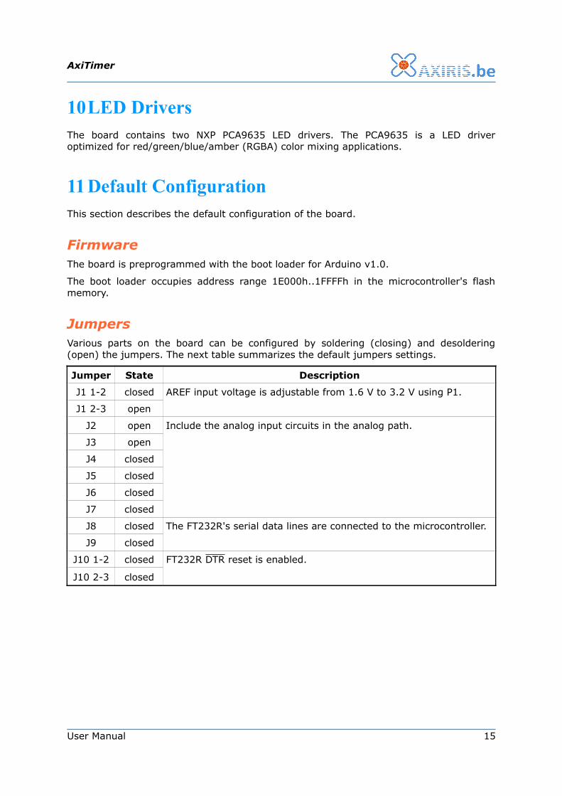
10LED DriversThe board contains two NXP PCA9635 LED drivers. The PCA9635 is a LED driver optimized for red/green/blue/amber (RGBA) color mixing applications.
11 Default ConfigurationThis section describes the default configuration of the board.
FirmwareThe board is preprogrammed with the boot loader for Arduino v1.0.
The boot loader occupies address range 1E000h..1FFFFh in the microcontroller's flash memory.
JumpersVarious parts on the board can be configured by soldering (closing) and desoldering (open) the jumpers. The next table summarizes the default jumpers settings.
Jumper State Description
J1 1-2 closed AREF input voltage is adjustable from 1.6 V to 3.2 V using P1.
J1 2-3 open
J2 open Include the analog input circuits in the analog path.
J3 open
J4 closed
J5 closed
J6 closed
J7 closed
J8 closed The FT232R's serial data lines are connected to the microcontroller.
J9 closed
J10 1-2 closed FT232R DTR reset is enabled.
J10 2-3 closed
User Manual 15

AxiTimer
12ArduinoThe board can be used with Arduino v1.0.
Be sure the FT232R DTR reset is enabled (see jumper J10). The Arduino environment uses this feature while uploading the program to the board.
The board is accompanied by a boot loader for Arduino. Use a serial programmer to load the boot loader is the microcontroller's flash memory.
13DisclaimerAxiris products are not designed, authorized or warranted to be suitable for use in space, nautical, space, military, medical, life-critical or safety-critical devices or equipment.
Axiris products are not designed, authorized or warranted to be suitable for use in applications where failure or malfunction of an Axiris product can result in personal injury, death, property damage or environmental damage.
Axiris accepts no liability for inclusion or use of Axiris products in such applications and such inclusion or use is at the customer's own risk. Should the customer use Axiris products for such application, the customer shall indemnify and hold Axiris harmless against all claims and damages.
14Contact InformationOfficial website: http://www.axiris.be/
16 User Manual