unit iii loaders and linkers - notes enginenotesengine.com/main/notes/it/5sem/ss/notes/unit iii...
TRANSCRIPT
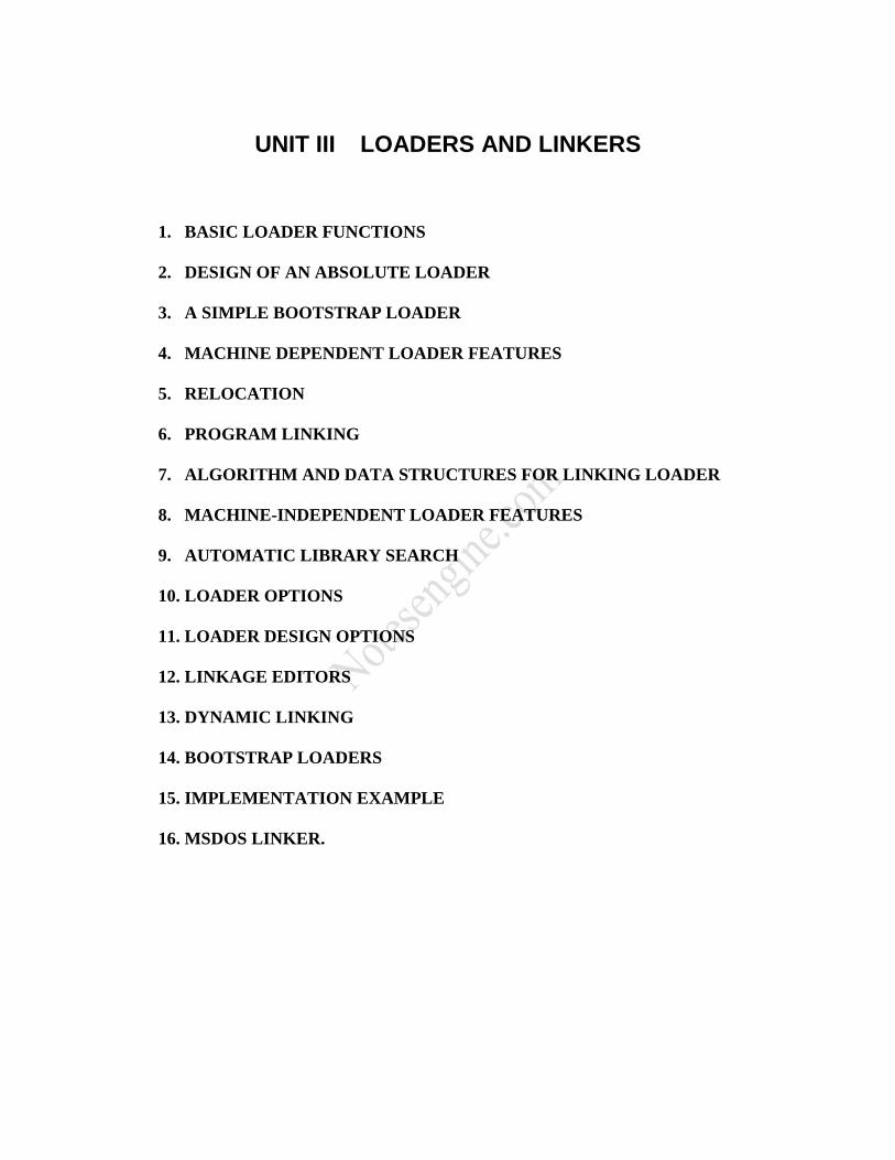
UNIT III LOADERS AND LINKERS
1. BASIC LOADER FUNCTIONS
2. DESIGN OF AN ABSOLUTE LOADER
3. A SIMPLE BOOTSTRAP LOADER
4. MACHINE DEPENDENT LOADER FEATURES
5. RELOCATION
6. PROGRAM LINKING
7. ALGORITHM AND DATA STRUCTURES FOR LINKING LOADER
8. MACHINE-INDEPENDENT LOADER FEATURES
9. AUTOMATIC LIBRARY SEARCH
10. LOADER OPTIONS
11. LOADER DESIGN OPTIONS
12. LINKAGE EDITORS
13. DYNAMIC LINKING
14. BOOTSTRAP LOADERS
15. IMPLEMENTATION EXAMPLE
16. MSDOS LINKER.

LINKERS AND LOADERS
1. Introduction
Installing a code in memory is called loading.
Memory
Assembler Loader
Obj. prog.
Source Object
program program
Figure 1. Loading an object code into memory
The task of integrating the program modules together is called linking.
relocatable
object
modules
Assembler Linker Loader
Module1
Module2
Source Linked
modules Object
Module 3
modules
Figure 2. Linking and loading as split processes

Linking and loading are frequently done at one time by a linking loader.
Module 1
Assembler Linking Loader Module 2
relocatable
Source object
modules modules object Module 3
modules
Figure 3. Linking loader
Types of loaders:
1. Absolute loaders
2. Relocating loaders
3. Linking loaders
2. Absolute Loaders
Assembler generates the code and writes instructions in a file together with their load
addresses.
The loader reads the file and places the code at the absolute address given in the file.
Example 1: Assume that the assembler generates the following code:
Address: instruction:
0100 F2 01 04
0103 47
0104 B5
… …
0200 05
0201 F2 02 00

The above code is written in the file as follows:
0100 location (2
bytes)
5 number of bytes
F2
01
04 code
47
B5
0200 location
4 number of bytes
05
F2 code
02
00
EOF

read 2 bytes
EOF Y
marker return
N
set LC to the byte read
read a byte and set NB to it
read a byte
place it into the memory location
pointed to by LC
NB = NB – 1 LC: Location
Counter
LC = LC + 1 NB: Number
of Bytes
N Y
NB>0
Figure 4. Absolute loader

3. Relocating Loader
independently
assembled modules
Assembler Relocating Loader
relocation information
Example 2: Assume that the following two relocatable codes and the associated DATs
are generated by the assembler:
Address: instruction:
0000 F2 00 04
0003 47
0004 B5
… …
DAT
0001
0000 05
0001 F2 00 00
… …
DAT
0002

The relocating loader adds the load-point of the code to all the references specified in
DAT. If the load-points of the above programs are 500 and 700, they are placed in the
memory as follows:
Memory
…
0500 3A
0501 05
0502 04
0503 47
0504 B5
…
0700 05
0701 F2
0702 07
0703 00
…

Get load-point
LC=0
Read a byte
EOF Y
marker return
N
Y LC is in N
DAT
Read next byte Place the byte at memory
location LC + Load Point
Add load point
LC = LC + 1
Place the bytes at memory
locations LC + Load Point
and LC + Load Point + 1
LC = LC + 2
Figure 5. Relocating loader

4. Linking Loader
Linking loaders perform four functions:
1. Allocation: allocating space in memory for programs
2. Linking: resolving external references between modules
3. Relocation: adjusting all address references
4. Loading: physically placing machine instructions and data in memory
Entry and External Points
When a statement in one module refers to a symbol in another module, it is called an
external reference (EXTREF).
Any symbol in a module that can be referred to from another module is called an
entry point (EXTDEF).
Module A Module B
EXTERNAL ALPHA, BETA ENTRY ALPHA, BETA
… …
LDA ALPHA
… ALPHA: …
LXI BETA …
… BETA: …

Example 3: The assembler has generated the object codes of the following source
programs where external references have not been resolved. These codes will be linked
and loaded into memory by a linking-loader.
Source programs Code generated by the assembler
H PROGA
R SIZE
R BUF
R SUM
PROGA: START 0 address
EXTREF SIZE, BUF, SUM
LDA #128 0000 29 01 28
STA SIZE 0003 0C __ __
LDA #1 0006 29 00 01
LDX #0 0009 05 00 00
L1: STA BUF, X 000C 0F __ __
ADD #1 000F 19 00 01
TIX SIZE 0012 2C __ __
JEQ L2 0015 30 00 1B (placed by the
assembler in pass 2)
J L1 0018 3C 00 0C (placed by the
assembler in pass 1)
L2: JSUB SUM 001B 48 __ __
RSUB 001E 4F 00 00
END DAT 0016
DAT 0019
M SIZE 0004
M BUF 000D
M SIZE 0013
M SUM 001B
H PROGB
D SUM 0000
R BUF
R SIZE
R TOT
PROGB: START 0
EXTDEF SUM
EXTREF SIZE, BUF, TOT
SUM: LDA #0 0000 29 00 00
LDX #0 0003 05 00 00
L3: ADD BUF, X 0006 1B __ __
TIX SIZE 0009 2C __ __
JEQ L4 000C 30 00 12 (placed by the
assembler in pass 2)
J L3 000F 3C 00 06 (placed by the
assembler in pass 1)

L4: STA TOT 0012 0C __ __
RSUB 0015 4F 00 00
END DAT 000D
DAT 0010
M BUF 0007
M SIZE 000A
M TOT 0013
H PROGC
D SIZE 0000
D TOT 0003
D BUF 0006
PROGC: START 0
EXTDEF SIZE, BUF, TOT
SIZE: RESW 1 0000 __ __ __
TOT: RESW 1 0003 __ __ __
BUF: RESW 200 0006 __ __ __
END 0009 __ __ __
000C __ __ __
… …
Relocatable machine codes
Assembler DATs Linker
H/D/R/M Information
The linker does two passes:
Pass1:
1. Gets load points of all programs.
2. Creates ESTAB table, using the information in D/R table. Calculates the absolute
address of each label in ESTAB as: load point + relative address.
Pass 2:
1. Using the M information and the absolute addresses in ESTAB, resolves the external
references in all programs.
2. Using the DAT information, adds load points to the local references.

ESTAB
program load point label absolute address
PROGA 1000
PROGB 2000
SUM 2000
PROGC 3000
SIZE 3000
TOT 3003
BUF 3006
Source programs Code generated Code generated
by the assembler at the end of linking
address address
PROGA: START 0
EXTREF SIZE, BUF, SUM
LDA #128 0000 29 01 28 0000 29 01 28
STA SIZE 0003 0C __ __ 0003 0C 30 00
LDA #1 0006 29 00 01 0006 29 00 01
LDX #0 0009 05 00 00 0009 05 00 00
L1: STA BUF, X 000C 0F __ __ 000C 0F 30
06
ADD #1 000F 19 00 01 000F 19 00 01
TIX SIZE 0012 2C __ __ 0012 2C 30 00
JEQ L2 0015 30 00 1B 0015 30 10 1B
J L1 0018 3C 00 0C 0018 3C 10 0C
L2: JSUB SUM 001B 48 __ __ 001B 48 20 00
RSUB 001E 4F 00 00 001E 4F 00 00
END
PROGB: START 0
EXTDEF SUM
EXTREF SIZE, BUF, TOT
SUM: LDA #0 0000 29 00 00 0000 29 00 00
LDX #0 0003 05 00 00 0003 05 00 00
L3: ADD BUF, X 0006 1B __ __ 0006 1B 30
06
TIX SIZE 0009 2C __ __ 0009 2C 30 00
JEQ L4 000C 30 00 12 000C 30 20 12
J L3 000F 3C 00 06 000F 3C 20 06
L4: STA TOT 0012 0C __ __ 0012 0C 30 03
RSUB 0015 4F 00 00 0015 4F 00 00
END

PROGC: START 0
EXTDEF SIZE, BUF, TOT
SIZE: RESW 1 0000 __ __ __ 0000 __ __ __
TOT: RESW 1 0003 __ __ __ 0003 __ __ __
BUF: RESW 200 0006 __ __ __ 0006 __ __ __
END 0009 __ __ __ 0009 __ __ __
000C __ __ __ 000C __ __ __
… … … …
Get Load Point
Read program name and
enter in ESTAB
Read a record
N
D record
Y
Enter symbol in ESTAB and
calculate absolute address
N end of
program
Y
N end of
all programs
Y
Pass 2
Figure 6. Pass 1 of the Linker

Get load point from ESTAB and
set LC to the load point
Read a record
Y
object code
Write it in the memory location N
pointed by LC
M record Y
N Find absolute address of the
symbol in ESTAB
and write it in memory location
pointed by
LC + relative location
Y
DAT record
Add load point to the value in memory N
location pointed by LC + DAT entry
Y more
records
N
Done
Figure 7. Pass 2 of the Linker

Linked codes are combined into a single file in the following format:
File format:
File name
File type Header
Number of
blocks
Load point (2
bytes)
Number of bytes
Code
Block 1
Checksum
…
…
…
Block N
Checksum:
To calculate checksum, add up all data in the block and take its low order byte.
When writing the code to the file, calculate checksum and write it at the end of each
block.
When installing the code in memory, recompute checksum and compare it with the
one read from the file.
Figure 8. Absolute loader, which reads the linked codes from a file and loads them into
the memory.

Return
Read header
NB = block count
Read load point
LC = load point
Read byte count
BC = byte count
Initialize checksum
Read a byte
Write the byte in memory
at location pointed to by LC
Add the byte to checksum
LC = LC + 1
BC = BC – 1
Y
BC>0
N
Read checksum byte
N
Checksum print error message
OK
Y
NB = NB – 1
NB: Number of blocks
Y LC: Location counter
NB > 0 BC: Byte count
N

5. Linking with Libraries
Library contains the relocatable image of each module. User programs are assembled
individually. The library routines used in user programs appear as external references.
Library routines
Relocatable DAT D/R/M
machine code Information
user Relocatable machine code
programs DAT Linker
D/R/M Information
Most linkers execute a default transparent search of a set of libraries that contain most
of the commonly called routines.
Searches are performed at the end of Pass 1
Library routines may have global symbols to be resolved, linker performs iterative
search until all symbols are resolved
Library files are designed to expedite the search. It is not necessary to go through the
whole file, instead, a library file header is reviewed, usually located at the beginning
of a file. The header contains all information.
Ex: Library file header
Routine Name Global Symbols Location in the File
… … …
… … …
Library routines are linked with user programs, between Pass 1 and Pass 2, while the
linker is resolving external references.

N Y
more Take an External reference
Pass 2 references
Resolve it
Entry
Y found for it in
user programs
N
Check all libraries (or only those specified by the user)
to find an Entry for it
N
found print error message
Y
Calculate a load point for the library routine
Configure direct addresses in the modules
Append the library routine to the user file
Merge the new D/R information to the
ESTAB
Figure 9. Linking the library routines with the user programs.

Dynamic Address Resolution
In dynamic linking, a subroutine is loaded and linked to the other programs when it is
first called during the execution. Dynamic linking allows several executing programs to
share the same copy of a subroutine. For example, a single copy of the routines in a
dynamic linking library (run-time library) can be loaded into the memory, and all
currently executing programs can be linked to this copy.
Dynamic linking provides the ability to load the routines only when they are needed. For
example, error correction routines are not need to be linked and loaded if no errors occur
during the program.
Dynamic linking also avoids the necessity of loading the entire library for each execution.
For example, a program may be calling a different routine depending on the input data.
Dynamic linking and loading has the following steps:
1. The user program makes a Load-and-Call request to the operating system
(dynamic loader).
2. The operating system examines its internal tables to determine whether or not the
routine is already loaded. If not, loads it into the memory. Then it transfers control
to the routine.
3. After the subroutine is processed, it returns control to the operating system.
4. The operating system returns control to the program that issued the request.
5. The subroutine may be retained in the memory for later use.
Machine Independent Loader Features
Automatic Library Search Automatic library call
The programmer does not need to take any action beyond mentioning the subroutine names as external references
Solution 1 Enter the symbols from each Refer record into ESTAB 2 When the definition is encountered (Define record), the address is assigned 3 At the end of Pass 1, the symbols in ESTAB that remain undefined represent
unresolved external references 4 The loader searches the specified (or standard) libraries for undefined
symbols or subroutines
The library search process may be repeated Since the subroutines fetched from a library may themselves contain
external references
Programmer defined subroutines have higher priority The programmer can override the standard subroutines in the library by
supplying their own routines
Library structures Assembled or compiled versions of the subroutines in a library can be

structured using a directory that gives the name of each routine and a pointer to its address within the library
Loader Options Many loaders have a special command language that is used to specify options. The
commands may be: In a separate input file In the source program Embedded in the primary input stream between programs
Command Language Specifying alternative sources of input
INCLUDE program-name(library-name)
Changing or deleting external reference DELETE name
CHANGE symbol1, symbol2
Controlling the automatic library search LIBRARY MYLIB
Specify that some references not be resolved NOCALL name
Specify the location at which execution is to begin
Example If we would like to evaluate the use of READ and WRITE instead of RDREC and
WRREC, for a temporary measure, we use the following loader commands INCLUDE READ(UTLIB)
INCLUDE WRITE(UTLIB)
DELETE RDREC, WRREC
CHANGE RDREC, READ
CHANGE WRREC, WRITE
If it is know that the statistical analysis is not to be performed in an execution NOCALL STDDEV, PLOT, CORREL
Loader Design Options Linkage Editors Definition
A linkage editor produces a linked version of the program (often called a load module or an executable image) which is written to a file or a library for later execution
Procedure A linkage editor performs relocation of all control sections relative to the
start of the linked program, resolves all external reference, and output a relocatable module for later execution
A simple relocating loader can be used to load the program into memory (one-pass without
external symbol table)
Linking Loader vs. Linkage Editors
Comparison Linking Loader: performs all linking and relocation operations, including library search if
specified, and loads the linked program directly into memory for execution Linkage Editors: produces a linked version of the program (often called a load module or
an executable image), which is written onto a file or library for later execution Resolution of external reference and library searching are only performed once for

linkage editor If a program is to be executed many times without being reassembled, the use of a linkage editor
substantially reduces the overhead required.
If a program is under development or is used infrequently, the use of a linking loader outperforms a
linkage editor
Dynamic Linking Comparison
Linkage editors perform linking operations before the program is loaded for execution
Linking loaders perform linking operations at load time Dynamic linking (dynamic loading, load on call) perform linking at execution
time Delayed Binding
Avoid the necessity of loading the entire library for each execution, i.e. load the routines only when they are needed
Allow several executing programs to share one copy of a subroutine or library (Dynamic Link Library, DLL)
Via an OS
Dynamic loader is one part of the OS Instead of executing a JSUB instruction that refers to an
external symbol, the program makes a load-and-call service request to the OS

Pass of control
User program OS
OS: load the subroutine
OS Subroutine
Subroutine OS
OS User program

Bootstrap loaders
When a computer is first turned on or restarted, bootstrap loader is executed. Bootstrap
loader is a simple absolute loader. Its function is to load the first system program to be
run by the computer, which is the operating system or a more complex loader that loads
the rest of the system.
Bootstrap loader is coded as a fixed-length record and added to the beginning of the
system programs that are to be loaded into an empty system. A built-in hardware or a
very simple program in ROM reads this record into the memory and transfers control to
it. When it is executed, it loads the following program, which is either the operating
system itself or other system programs to be run without the operating system.
MS DOS linker
• object file (.OBJ)
– generated by assembler (or compiler)
– format
THEADR name of this object module
PUBDEF external symbols defined in this module
EXTDEF external symbols used here
TYPDEF data types for pubdef and extdef
SEGDEF describes segments in this module
GRPDEF segment grouping
LNAMES name list indexed by segdef and grpdef
LEDATA binary image of code
LIDATA repeated data
FIXUPP modification record
MODEND end
• LINK
– pass 1:
» allocates segments defined in SEGDEF
» resolve external symbols
– pass 2:
» prepare memory image
• if needed, disk space is also used
» expand LIDATA
» relocations within segment
» write .EXE file