1 chapter 3 loaders and linkers source program assembler object code loader executable code linker
TRANSCRIPT
1
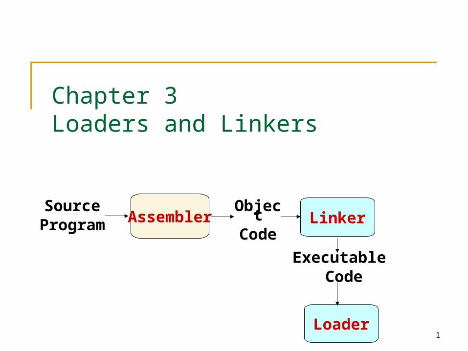
Chapter 3Loaders and Linkers
SourceProgra
mAssembler
Object
Code
Loader
Executable Code
Linker
2
3.1 Basic Loader Functions
In Chapter 2, we discussions Loading: brings the OP into memory for
execution Relocating: modifies the OP so that it can be
loaded at an address different form the location originally specified.
Linking: combines two or more separate OP In Chapter 3, we will discussion
A loader brings an object program into memory and starting its execution.
A linker performs the linking operations and a separate loader to handle relocation and loading.
3
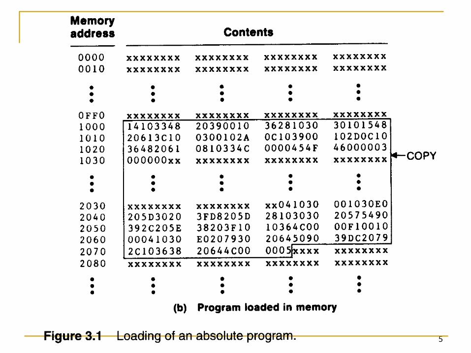
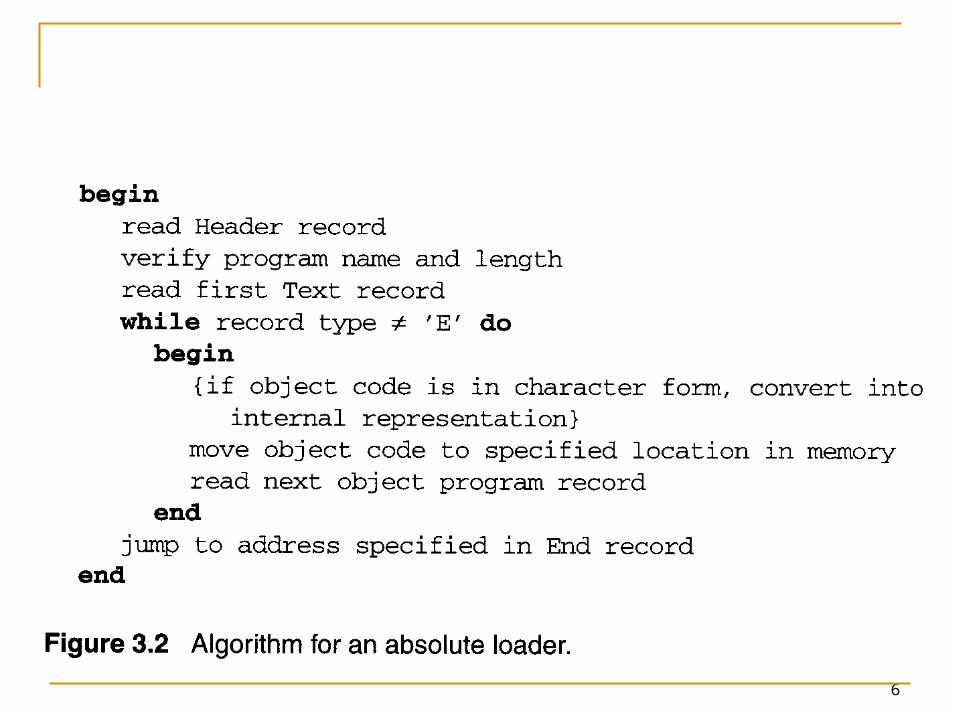
3.1 Basic Loader Functions 3.1.1 Design of an Absolute Loader
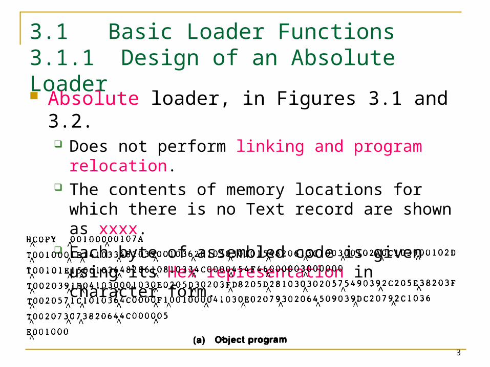
Absolute loader, in Figures 3.1 and 3.2. Does not perform linking and program
relocation. The contents of memory locations for which
there is no Text record are shown as xxxx. Each byte of assembled code is given using its
Hex representation in character form.
4
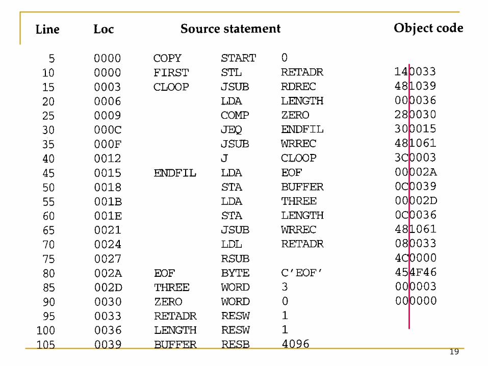
3.1.1 Design of an Absolute Loader
Absolute loader, in Figure 3.1 and 3.2. STL instruction, pair of characters 14, when
these are read by loader, they will occupy two bytes of memory.
14 (Hex 31 34) ----> 00010100 (one byte) For execution, the operation code must be
store in a single byte with hexadecimal value 14.
Each pair of bytes must be packed together into one byte.
Each printed character represents one half-byte.
5
6
7
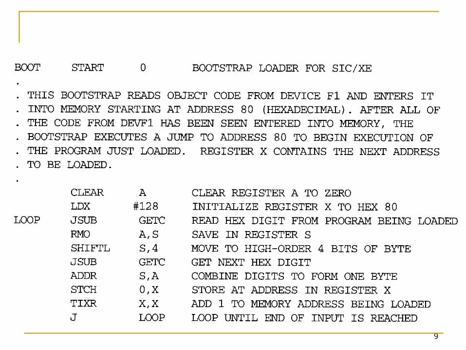
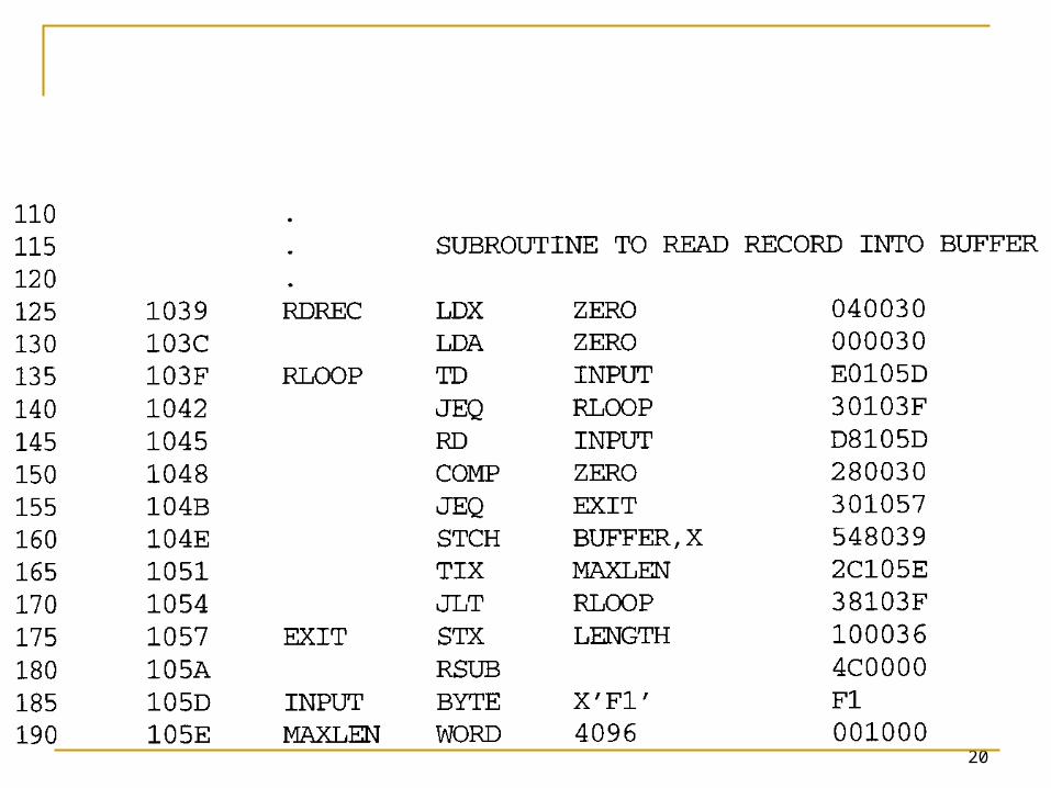
3.1.2 A Simple Bootstrap Loader
A bootstrap loader, Figure 3.3. Loads the first program to be run by the
computer--- usually an operating system. The bootstrap itself begins at address 0 in the
memory. It loads the OS or some other program starting
at address 80.
8
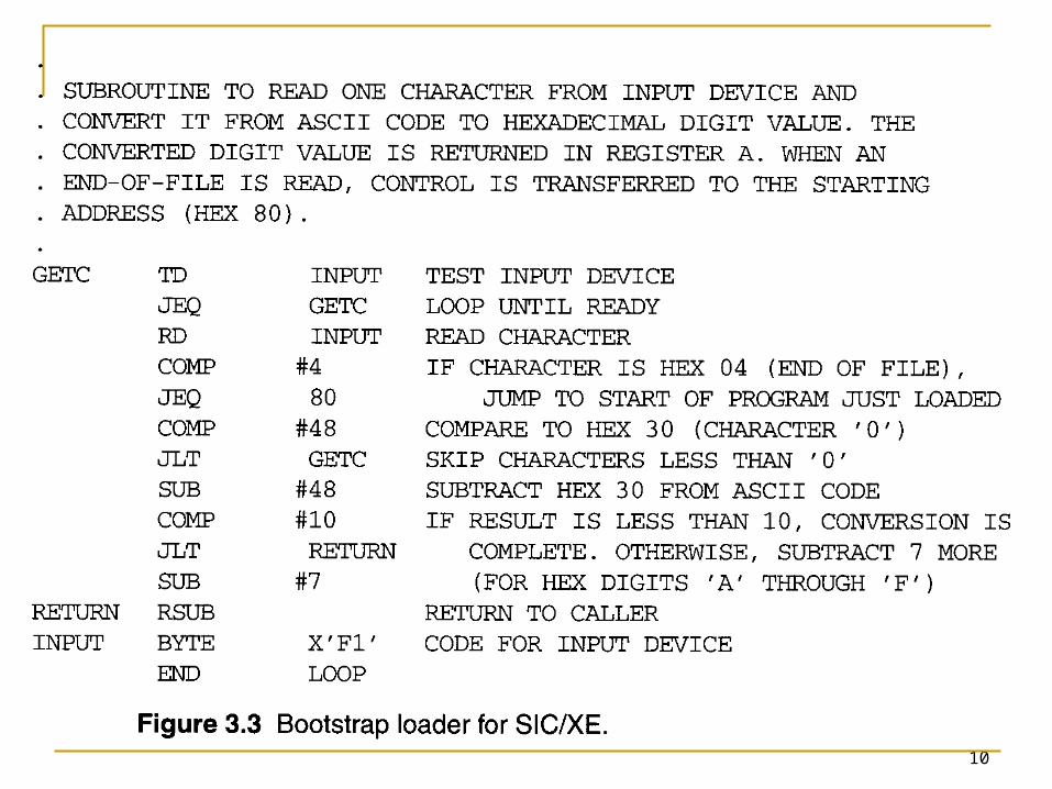
3.1.2 A Simple Bootstrap Loader
A bootstrap loader, Figure 3.3. Each byte of object code to be loaded is
represented on device F1 as two Hex digits (by GETC subroutines).
The ASCII code for the character 0 (Hex 30) is converted to the numeric value 0.
The object code from device F1 is always loaded into consecutive bytes of memory, starting at address 80.
9
10
11
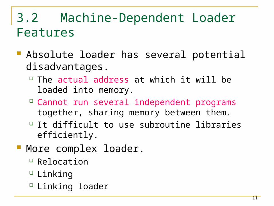
3.2 Machine-Dependent Loader Features
Absolute loader has several potential disadvantages. The actual address at which it will be loaded
into memory. Cannot run several independent programs
together, sharing memory between them. It difficult to use subroutine libraries efficiently.
More complex loader. Relocation Linking Linking loader
12
3.2.1 Relocation
Relocating loaders, two methods: Modification record (for SIC/XE) Relocation bit (for SIC)
13
14
15
16
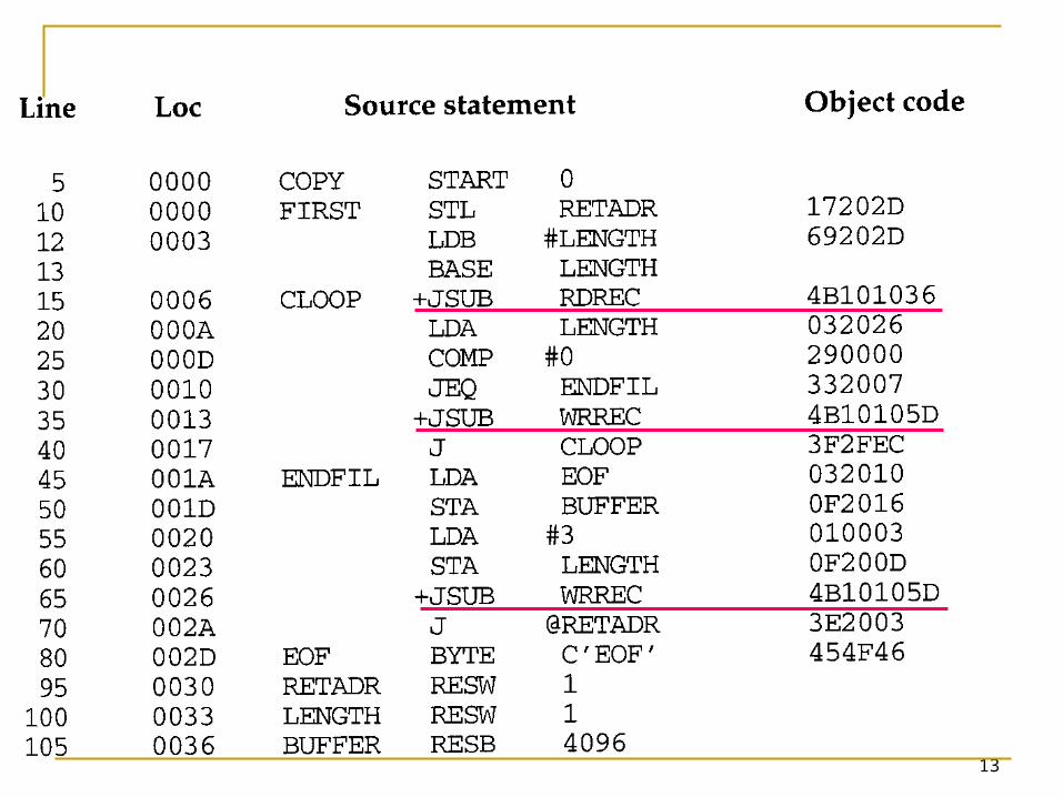
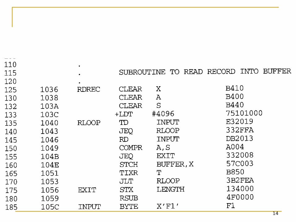
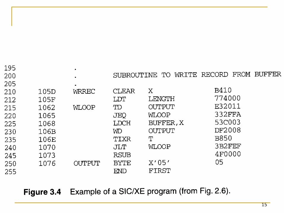
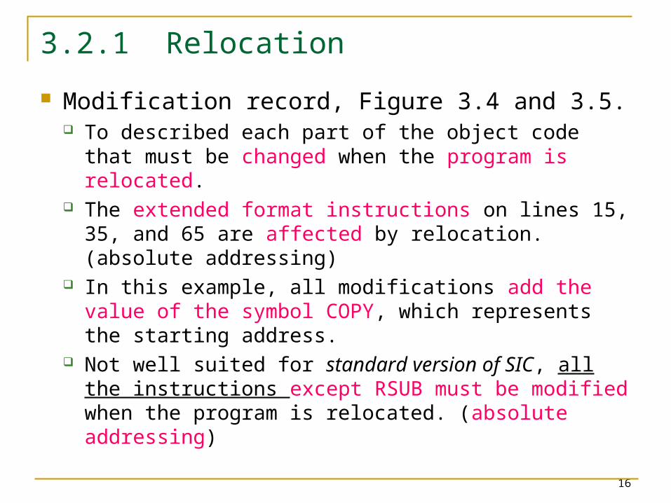
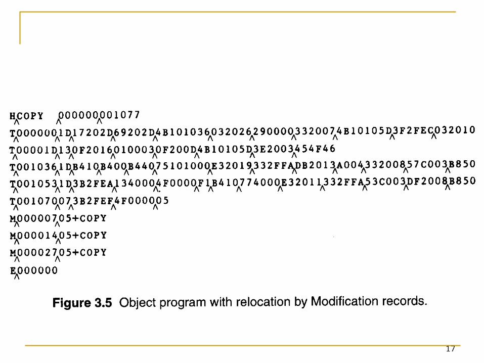
3.2.1 Relocation
Modification record, Figure 3.4 and 3.5. To described each part of the object code that
must be changed when the program is relocated. The extended format instructions on lines 15, 35,
and 65 are affected by relocation. (absolute addressing)
In this example, all modifications add the value of the symbol COPY, which represents the starting address.
Not well suited for standard version of SIC, all the instructions except RSUB must be modified when the program is relocated. (absolute addressing)
17
18
3.2.1 Relocation
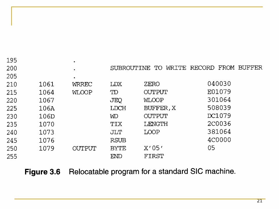
Figure 3.6 needs 31 Modification records. Relocation bit, Figure 3.6 and 3.7.
A relocation bit associated with each word of object code.
The relocation bits are gathered together into a bit mask following the length indicator in each Text record.
If bit=1, the corresponding word of object code is relocated.
19
20
21
22
3.2.1 Relocation
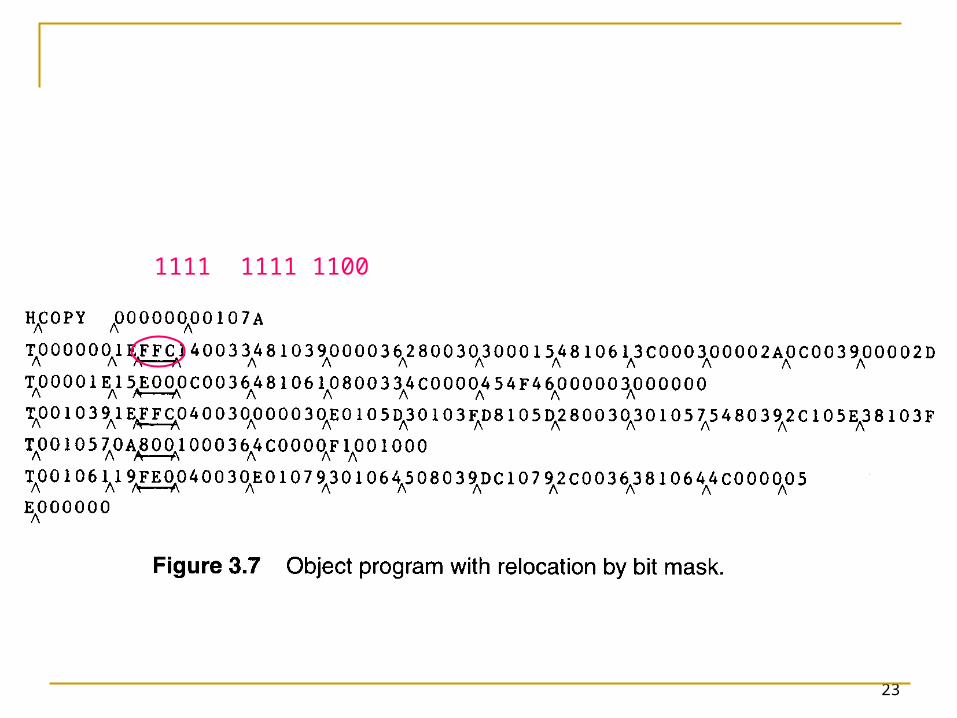
Relocation bit, Figure 3.6 and 3.7. In Figure 3.7, T000000^1E^FFC^
(111111111100) specifics that all 10 words of object code are to be modified.
On line 210 begins a new Text record even though there is room for it in the preceding record.
Any value that is to be modified during relocation must coincide with one of these 3-byte segments so that it corresponding to a relocation bit.
Because of the 1-byte data value generated form line 185, this instruction must begin a new Text record in object program.
23
1111 1111 1100
24
3.2.2 Program Linking
In Section 2.3.5 showed a program made up of three controls sections. Assembled together or assembled
independently.
25
3.2.2 Program Linking
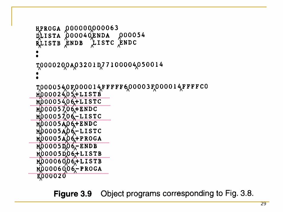
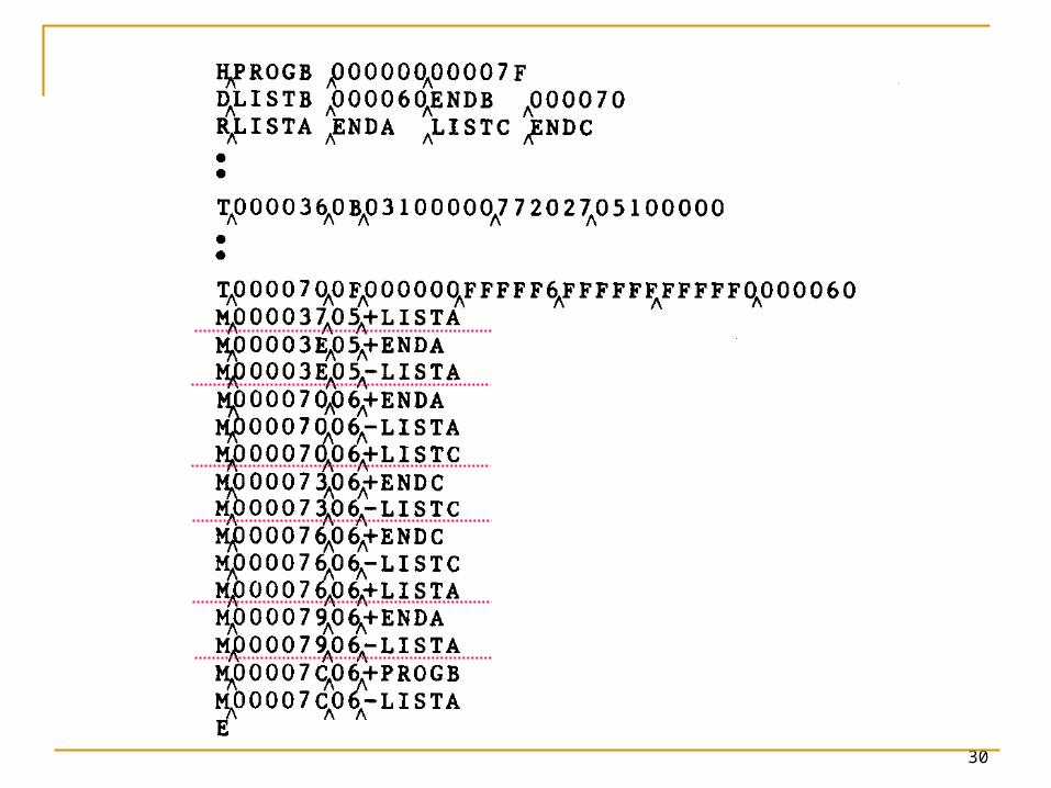
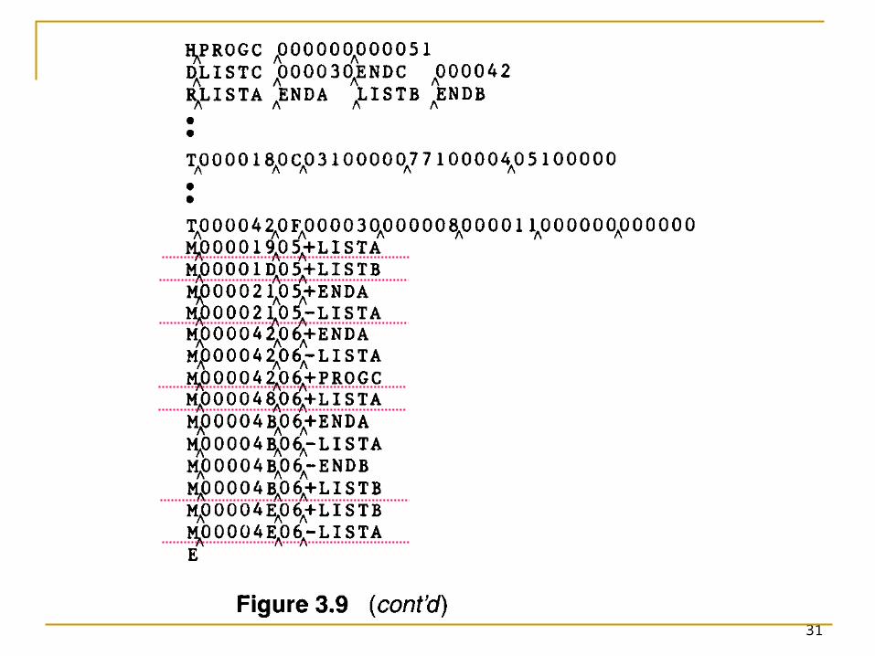
Consider the three programs in Fig. 3.8 and 3.9. Each of which consists of a single control
section. A list of items, LISTA---ENDA, LISTB---ENDB,
LISTC---ENDC. Note that each program contains exactly the
same set of references to these external symbols.
Instruction operands (REF1, REF2, REF3). The values of data words (REF4 through REF8). Not involved in the relocation and linking are
omitted.
26
27
28
29
30
31
32
3.2.2 Program Linking
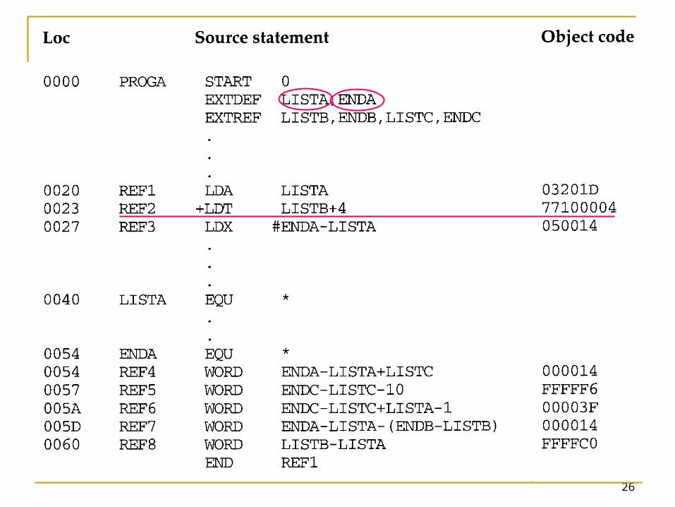
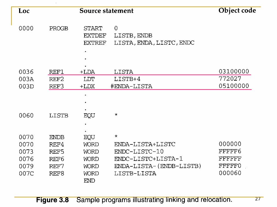
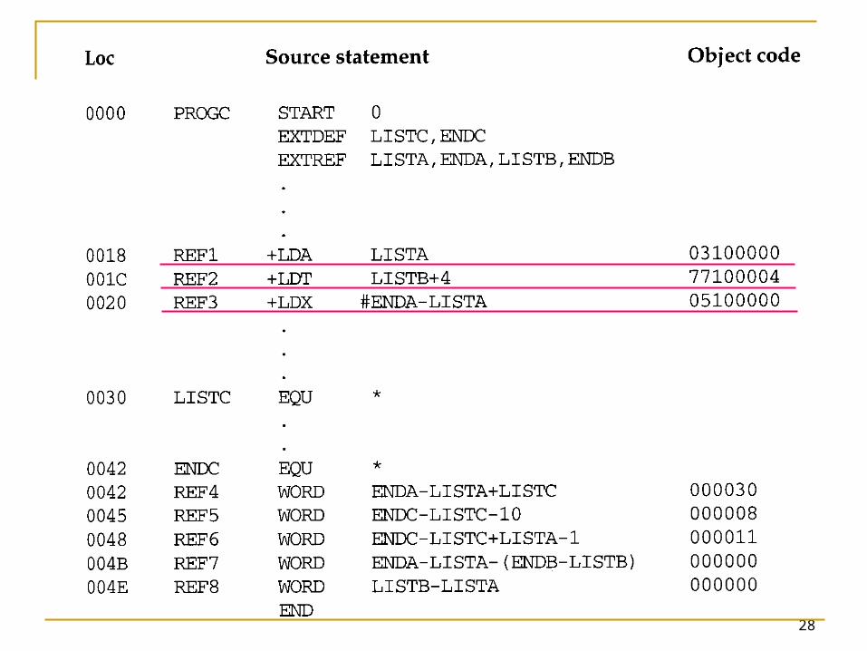
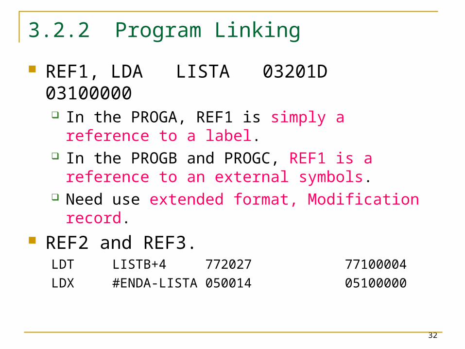
REF1, LDA LISTA 03201D 03100000 In the PROGA, REF1 is simply a reference to a
label. In the PROGB and PROGC, REF1 is a reference
to an external symbols. Need use extended format, Modification
record. REF2 and REF3.
LDT LISTB+4 772027 77100004LDX #ENDA-LISTA 050014 05100000
33
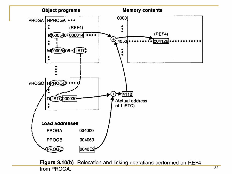
3.2.2 Program Linking
REF4 through REF8, WORD ENDA-LISTA+LISTC 000014+000000
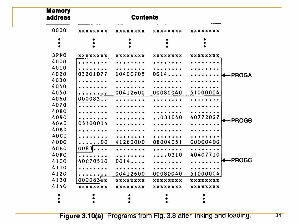
Figure 3.10(a) and 3.10(b) Shows these three programs as they might
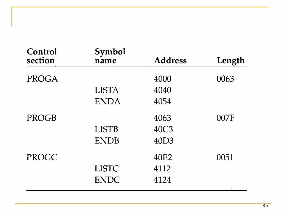
appear in memory after loading and linking. PROGA 004000, PROGB 004063, PROGC
0040E2. REF4 through REF8 in the same value. For the references that are instruction
operands, the calculated values after loading do not always appear to be equal.
Target address, REF1 4040.
34
35
36
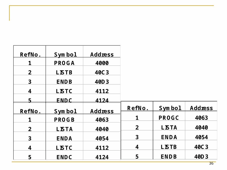
Ref No. Symbol Address
1 PROGC 4063
2 LISTA 4040
3 ENDA 4054
4 LISTB 40C3
5 ENDB 40D3
Ref No. Symbol Address
1 PROGA 4000
2 LISTB 40C3
3 ENDB 40D3
4 LISTC 4112
5 ENDC 4124
Ref No. Symbol Address
1 PROGB 4063
2 LISTA 4040
3 ENDA 4054
4 LISTC 4112
5 ENDC 4124
37
38
3.2.3 Algorithm and Data Structure for a Linking Loader
A linking loader usually makes two passes Pass 1 assigns addresses to all external
symbols. Pass 2 performs the actual loading, relocation,
and linking. The main data structure is ESTAB (hashing
table).
39
3.2.3 Algorithm and Data Structure for a Linking Loader
A linking loader usually makes two passes ESTAB is used to store the name and address of
each external symbol in the set of control sections being loaded.
Two variables PROGADDR and CSADDR. PROGADDR is the beginning address in memory
where the linked program is to be loaded. CSADDR contains the starting address assigned
to the control section currently being scanned by the loader.
40
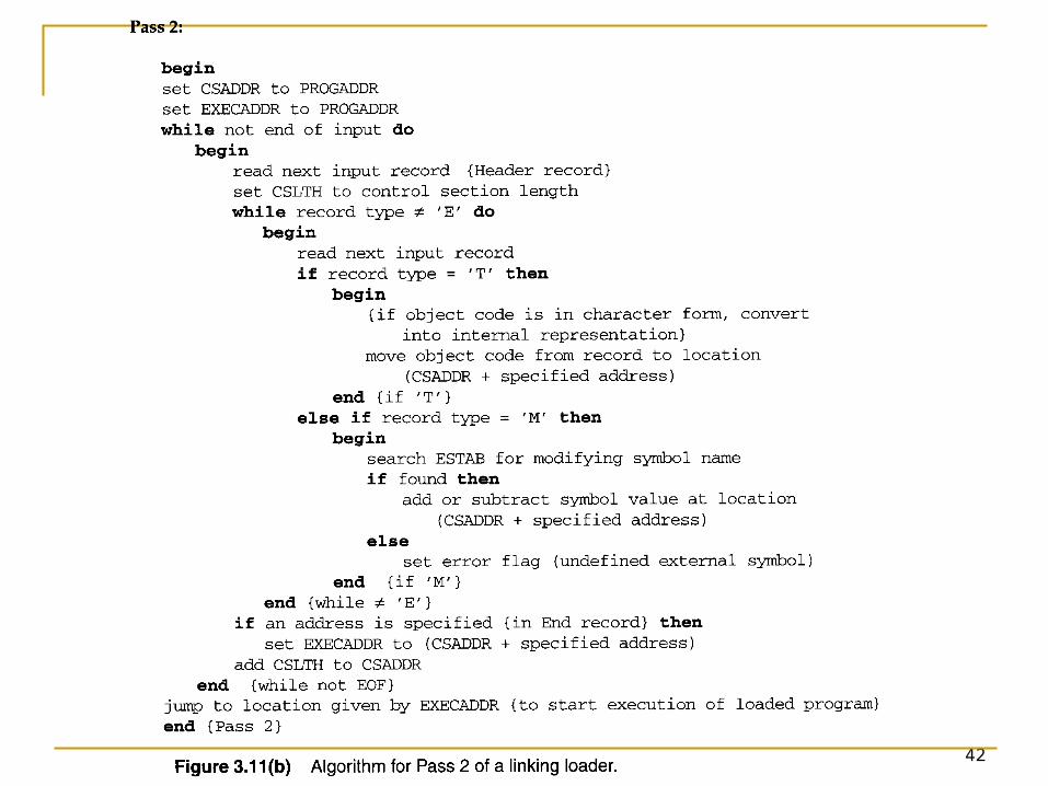
3.2.3 Algorithm and Data Structure for a Linking Loader The linking loader algorithm, Fig 3.11(a) & (b).
In Pass 1, concerned only Header and Defined records.
CSADDR+CSLTH = the next CSADDR. A load map is generated. In Pass 2, as each Text record is read, the object
code is moved to the specified address (plus the current value of CSADDR).
When a Modification record is encountered, the symbol whose value is to be used for modification is looked up in ESTAB.
This value is then added to or subtracted from the indicated location in memory.

41
42
43
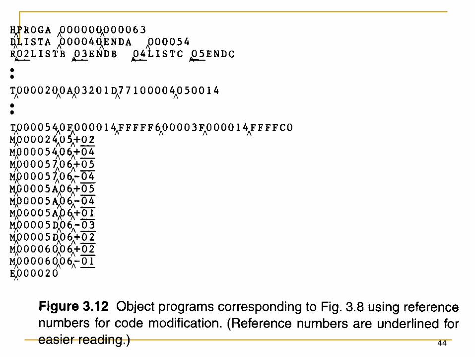
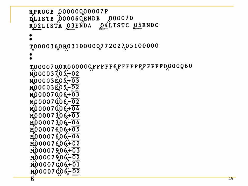
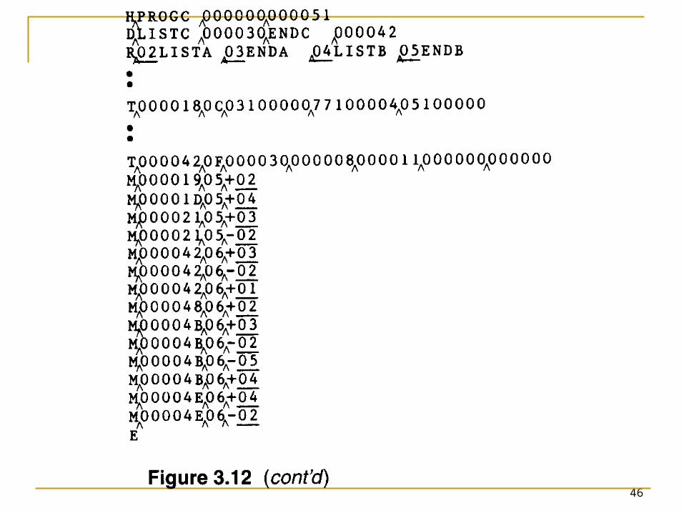
3.2.3 Algorithm and Data Structure for a Linking Loader
The algorithm can be made more efficient. A reference number, is used in Modification
records. The number 01 to the control section name. Figure 3.12, the main advantage of this
reference-number mechanism is that it avoids multiple searches of ESTAB for the same symbol during the loading of a control section.
44
45
46
47
3.3 Machine-Independent Loader Features3.3.1 Automatic Library Search
Many linking loaders Can automatically incorporate routines form a
subprogram library into the program being loaded.
A standard system library The subroutines called by the program begin
loaded are automatically fetched from the library, linked with the main program, and loaded.
48
3.3.1 Automatic Library Search
Automatic library call At the end of Pass 1, the symbols in ESTAB that
remain undefined represent unresolved external references.
The loader searches the library
49
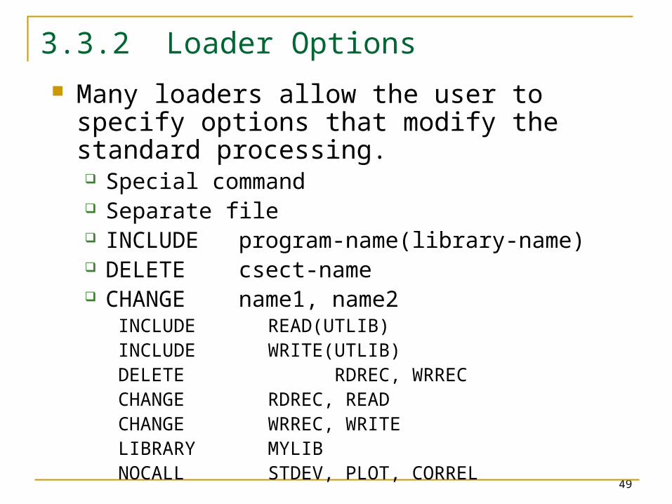
3.3.2 Loader Options
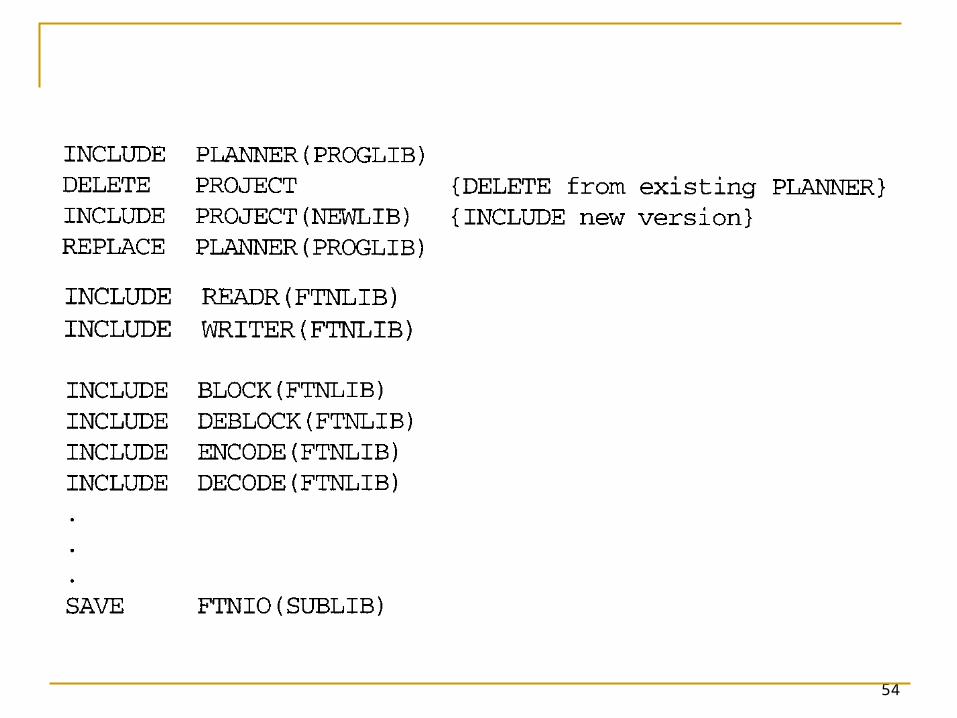
Many loaders allow the user to specify options that modify the standard processing. Special command Separate file INCLUDE program-name(library-name) DELETE csect-name CHANGE name1, name2
INCLUDE READ(UTLIB)INCLUDE WRITE(UTLIB)DELETE RDREC, WRRECCHANGE RDREC, READCHANGE WRREC, WRITELIBRARY MYLIBNOCALL STDEV, PLOT, CORREL
50
3.4 Loader Design Options3.4.1 Linkage Editors
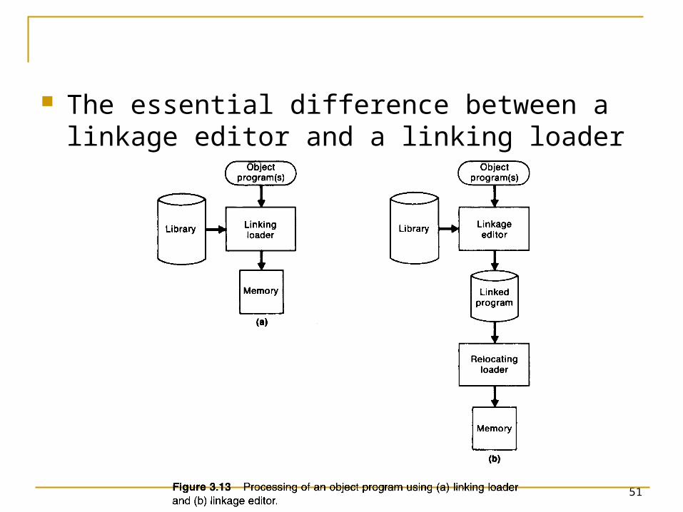
Fig 3.13 shows the difference between linking loader and linkage editor. The source program is first assembled or
compiled, producing an OP. Linking loader
A linking loader performs all linking and relocation operations, including automatic library search if specified, and loads the linked program directly into memory for execution.
51
The essential difference between a linkage editor and a linking loader
52
3.4.1 Linkage Editors
Linkage editor A linkage editor produces a linked version of the
program (load module or executable image), which is written to a file or library for later execution.
When the user is ready to run the linked program, a simple relocating loader can be used to load the program into memory.
The only object code modification necessary is the addition of an actual load address to relative values within the program.
The LE performs relocation of all control sections relative to the start of the linked program.
53
3.4.1 Linkage Editors
All items that need to be modified at load time have values that are relative to the start of the linked program.
If a program is to be executed many times without being reassembled, the use of a LE substantially reduces the overhead required.
LE can perform many useful functions besides simply preparing an OP for execution.
54
55
3.4.2 Dynamic Linking
Linking loaders perform these same operations at load time.
Linkage editors perform linking operations before the program is load for execution.
56
3.4.2 Dynamic Linking
Dynamic linking (dynamic loading, load on call) Postpones the linking function until execution
time. A subroutine is loaded and linked to the rest
the program when is first loaded. Dynamic linking is often used to allow several
executing program to share one copy of a subroutine or library. Run-time library (C language), dynamic link library A single copy of the routines in this library could be
loaded into the memory of the computer.
57
3.4.2 Dynamic Linking
Dynamic linking provides the ability to load the routines only when (and if) they are needed. For example, that a program contains
subroutines that correct or clearly diagnose error in the input data during execution.
If such error are rare, the correction and diagnostic routines may not be used at all during most execution of the program.
However, if the program were completely linked before execution, these subroutines need to be loaded and linked every time.
58
3.4.2 Dynamic Linking
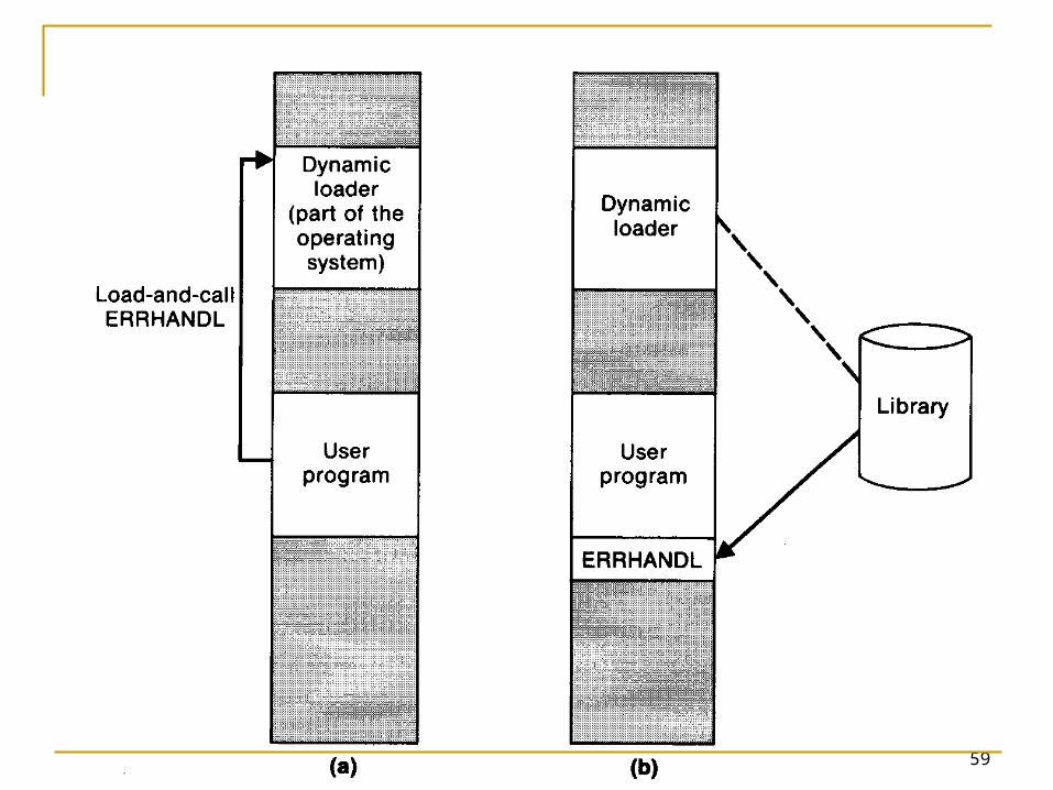
Dynamic linking avoids the necessity of loading the entire library for each execution.
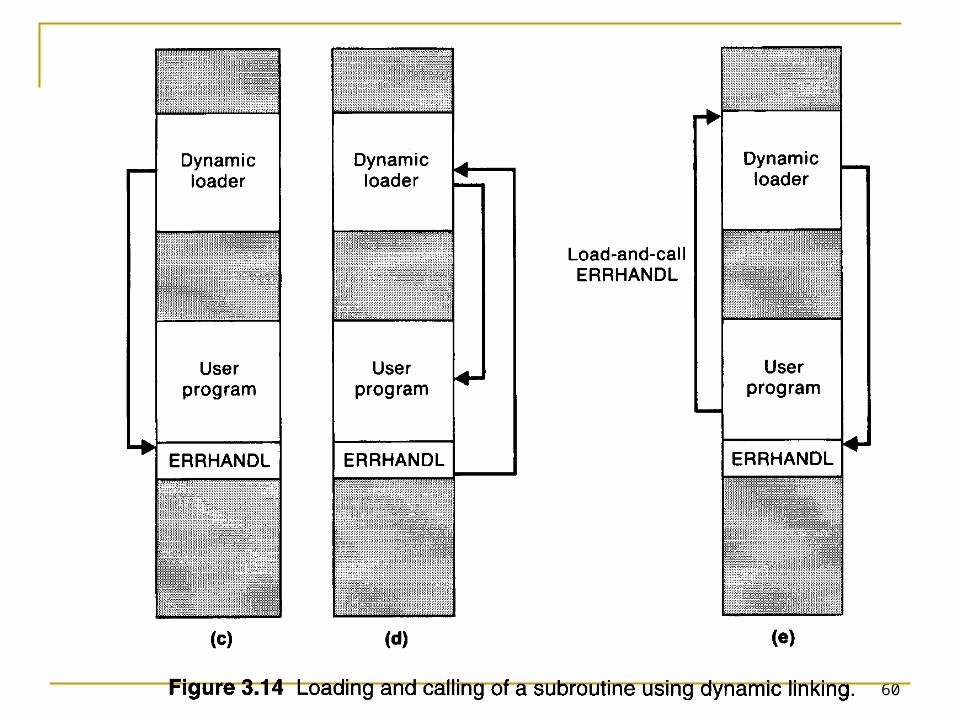
Fig. 3.14 illustrates a method in which routines that are to be dynamically loaded must be called via an operating system (OS) service request.
59
60
61
3.4.2 Dynamic Linking
The program makes a load-on-call service request to OS. The parameter of this request is the symbolic name of the routine to be loaded.
OS examines its internal tables to determine whether or not the routine is already loaded. If necessary, the routine is loaded form the specified user or system libraries.
Control id then passed form OS to the routine being called.
When the called subroutine completes its processing, OS then returns control to the program that issued the request.
If a subroutine is still in memory, a second call to it may not require another load operation.
62
3.4.3 Bootstrap Loaders
An absolute loader program is permanently resident in a read-only memory (ROM) Hardware signal occurs
The program is executed directly in the ROM
The program is copied from ROM to main memory and executed there.
63
3.4.3 Bootstrap Loaders
Bootstrap and bootstrap loader Reads a fixed-length record form some device
into memory at a fixed location. After the read operation is complete, control is
automatically transferred to the address in memory.
If the loading process requires more instructions than can be read in a single record, this first record causes the reading of others, and these in turn can cause the reading of more records.