unit ii signals & errors · bit rate it is the number of bits transmitted in one second. it is...
TRANSCRIPT

UNIT II SIGNALS & ERRORS
Analog and digital signals – Encoding and modulation – Parallel and serial transmission –
DTE/DCE – Types of errors – Error detection and correction – Data link control – Line
discipline – Flow control – Error control.
INTRODUCTION
Computer networks are designed to transfer data from one point to another. During
transit data is in the form of electromagnetic signals. Hence it is important to study data
and signals before we move to further concepts in data communication.
DATA & SIGNALS
To be transmitted, data must be transformed to
electromagnetic signals.
Signals Information can be in the form of data, voice, picture, and so on. To be transmitted,
information must be transformed into electromagnetic signals.
Data can be Analog or Digital.
1. Analog data refers to information that is continuous; ex.
sounds made by a human voice
2. Digital data refers to information that has discrete states.
Digital data take on discrete values.
For example, data are stored in computer memory in the form of Os and 1s
Signals can be of two types:
1. Analog Signal: They have infinite values in a range. 2. Digital Signal: They have limited number of defined
values
Figure: a. Analog Signal b. Digital Signal* Periodic & Non Periodic Signals
Signals which repeat itself after a fixed time period are called Periodic
Signals.Signals which do not repeat itself after a fixed time period are called
Non-Periodic Signals. In data communications, we commonly use
periodic analog signals and non-periodic digital signals.

ANALOG SIGNAL
An analog signal has infinitely many levels of intensity over a period of
time.
As the wave moves from value A to value B, it passes through and
includes an infinite number of values along its
path as it can be seen in the figure below.
A simple analog signal is a sine wave that cannot be further decomposed
into simpler signals.
Fig. Sine wave
A sine wave is characterized by three parameters: 1. Peak Amplitude 2. Frequency 3. Phase
Characteristics of an Analog Signal
Peak Amplitude
The amplitude of a signal is the absolute value of its intensity at time t
The peak amplitude of a signal is the absolute value of the highest intensity.
The amplitude of a signal is proportional to the energy carried by the signal
Fig. Amplitude of a sine wave
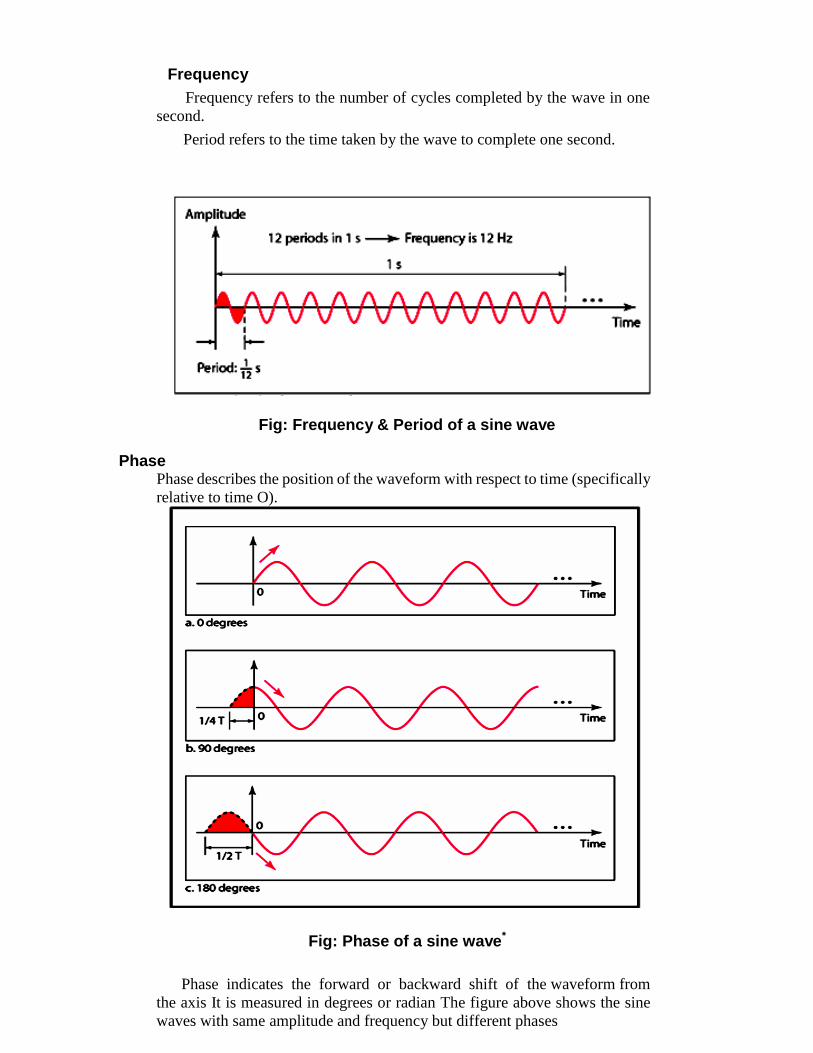
Frequency
Frequency refers to the number of cycles completed by the wave in one
second.
Period refers to the time taken by the wave to complete one second.
Fig: Frequency & Period of a sine wave
Phase Phase describes the position of the waveform with respect to time (specifically
relative to time O).
Fig: Phase of a sine wave*
Phase indicates the forward or backward shift of the waveform from
the axis It is measured in degrees or radian The figure above shows the sine
waves with same amplitude and frequency but different phases

Amplitude Change
Frequency Change
Phase Change

Composite signals
To decompose a composite signal into its components, Fourier analysis is needed.
Signal with DC Component
Bandwidth
Relation between Frequency & Period Frequency & Period are inverse of each other.
It is indicated by the following formula:
Example1. A wave has a frequency of 100hz. Its period(T) is given by
T = 1/ F = 1/ 100 = 0.01 sec
Example2. A wave completes its one cycle in 0.25 seconds. Its frequency is
given by
F = 1 / T = 1 / 0.25 = 4 Hz

Wavelength
The wavelength of a signal refers to the relationship between frequency
(or period) and propagation speed of the wave through a medium.
The wavelength is the distance a signal travels in one period.
It is given by
Wavelength = Propagation Speed X Period OR
Wavelength =Propagation Speed X 1 Frequency
It is represented by the symbol : λ (pronounced as lamda)
It is measured in micrometers
It varies from one medium to another.
Time Domain and Frequency domain representation of signals
A sine wave can be represented either in the time domain or frequency
domain.The time-domain plot shows changes in signal amplitude with
respect to time. It indicates time and amplitude relation of a signal.
The frequency-domain plot shows signal frequency and peak
amplitude. The figure below show time and frequency domain plots of
three sine waves.
Time and Frequency Domain
Time and frequency domains for different signals

Fig: Time domain and frequency domain plots of three sine waves*
A complete sine wave in the time domain can be represented by one
single spike in the frequency domain
Composite Signal
A composite signal is a combination of two or more simple sine waves
with different frequency, phase and amplitude.
If the composite signal is periodic, the decomposition gives a series of
signals with discrete frequencies; if the composite signal is non-periodic,
the decomposition gives a
combination of sine waves with continuous frequencies.

Fig: A Composite signal with three component signals
For data communication a simple sine wave is not useful, what is used is
a composite signal which is a combination of many simple sine waves.
According to French Mathematician, Jean Baptist, any composite
signal is a combination of simple sine waves with different amplitudes and
frequencies and phases.
Composite signals can be periodic or non periodic.
A periodic composite signal can be decomposed into a series of
signals with discrete frequencies.
A non-periodic signal when decomposed gives a combination
of sine waves with continuous frequencies.
Fig The time and frequency domains of a non-periodic composite analog signal
Composite Waveform

Digital Signal
Information can also be explained in the form of a digital signal.
A digital signal can be explained with the help of following points:
Definition:-
A digital is a signal that has discrete values.
The signal will have value that is not continuous.
LEVEL
Information in a digital signal can be represented in the form of voltage
levels.
Ex. In the signal shown below, a ‗1‘ is represented by a positive voltage
and a ‗0‘ is represented by a Zero voltage.
Fig: A digital signal with Two levels. „1‟ represented by a positive voltage and „0‟ represented by a negative voltage

A Signal can have more than two levels
11 10 01 00 00 01 10 10
LEVEL 4
LEVEL 3
LEVEL 2
LEVEL
1
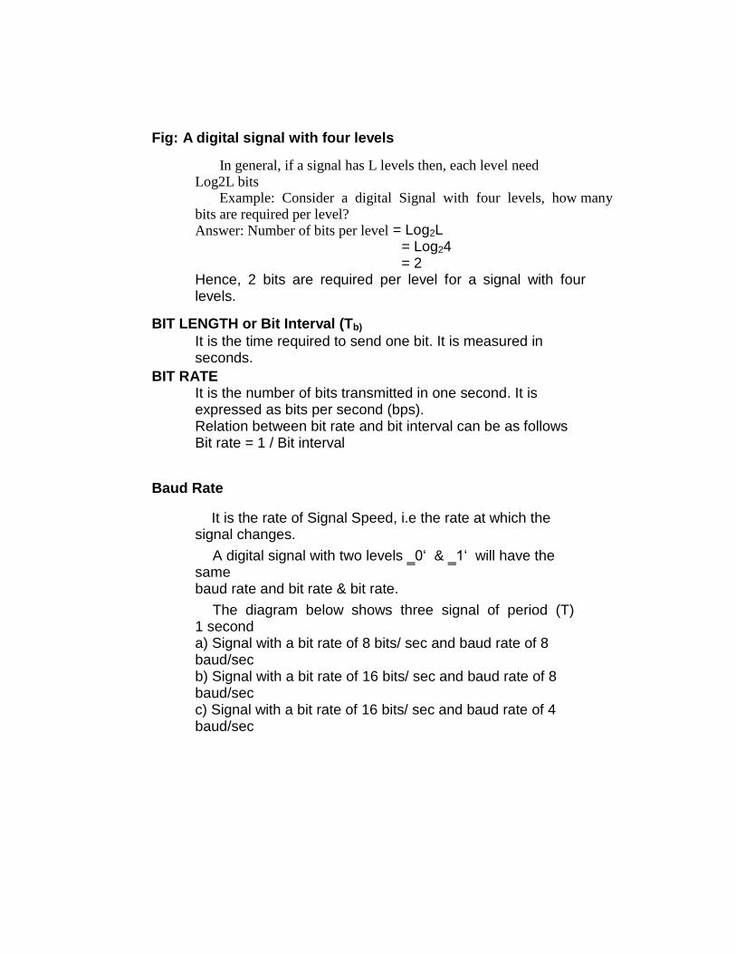
Fig: A digital signal with four levels
In general, if a signal has L levels then, each level need Log2L bits
Example: Consider a digital Signal with four levels, how many bits are required per level? Answer: Number of bits per level = Log2L
= Log24 = 2
Hence, 2 bits are required per level for a signal with four levels.
BIT LENGTH or Bit Interval (Tb)
It is the time required to send one bit. It is measured in seconds.
BIT RATE It is the number of bits transmitted in one second. It is expressed as bits per second (bps). Relation between bit rate and bit interval can be as follows Bit rate = 1 / Bit interval
Baud Rate
It is the rate of Signal Speed, i.e the rate at which the signal changes.
A digital signal with two levels ‗0‘ & ‗1‘ will have the same baud rate and bit rate & bit rate.
The diagram below shows three signal of period (T) 1 second a) Signal with a bit rate of 8 bits/ sec and baud rate of 8 baud/sec b) Signal with a bit rate of 16 bits/ sec and baud rate of 8 baud/sec c) Signal with a bit rate of 16 bits/ sec and baud rate of 4 baud/sec

Fig: Three signals with different bit rates and baud rates Bit Interval and Bit Rate
The bit interval is the time required to send one single bit. The bit rate is the
number of bit intervals per second.

Decomposition of a Digital Signal
A digital signal can be decomposed into an infinite number of sine waves
(harmonics).
Harmonics of a Digital Signal
Exact and Significant Spectrums
The significant spectrum of a digital signal is the portion of the signal’s spectrum
that can adequately reproduce the original signal.

Analog and Digital
Analog refers to something that is continuous-a set of specific points of data and all
possible points between. Digital refers to something that is discrete-a set of specific points
of data with no other points in between.
Analog and Digital Data
Data can be analog or digital. An example of analog data is the human voice. An
example of digital data is data stored , the memory of a computer in the form of 0s and 1s.
Analog and Digital Signals
Signals can be analog or digital. Analog signals can have any value in a range;
digital signals can have only a limited number of values.
Transformation of Information
to Signals
Analog and Digital Signals

Aperiodic and periodic signals
Aperiodic signals
An aperiodic, or nonperiodic, signal changes constantly without exhibiting a
pattern or cycle that repeats over time. An aperiodic, or nonperiodic, signal has no
repetitive pattern. An aperiodic signal can be decomposed into an infinite number
of periodic signals.
Periodic Signals
A signal is a periodic signal if it completes a pattern within a measurable
time frame, called a period, and repeats that pattern over identical subsequent
periods. The completion of one full pattern is called a cycle. A periodic signal
consists of a continuously repeated pattern. The period of a signal (T) is expressed
in seconds.
BANDWIDTH OF A SIGNAL
Bandwidth can be defined as the portion of the electromagnetic spectrum
occupied by the signal
It may also be defined as the frequency range over which a signal is
transmitted.
Different types of signals have different bandwidth. Ex. Voice signal, music
signal, etc

Bandwidth of analog and digital signals are calculated in separate ways; analog
signal bandwidth is measured in terms of its frequency (hz) but digital signal
bandwidth is measured in terms of bit rate (bits per second, bps)
Bandwidth of signal is different from bandwidth of the medium/channel
Bandwidth of an analog signal
Bandwidth of an analog signal is expressed in terms of its frequencies.
It is defined as the range of frequencies that the composite analog signal
carries.
It is calculated by the difference between the maximum frequency and the
minimum frequency.
Consider the signal shown in the diagram below:
Fig: Bandwidth of a signal in time domain and frequency domain
The signal shown in the diagram is an composite analog signal with many
component signals.
It has a minimum frequency of F1 = 30Hz and maximum frequency of F2 =
90Hz.
Hence the bandwidth is given by F2 – F1 = 90 – 30 = 60 Hz
Bandwidth of a digital signal
It is defined as the maximum bit rate of the signal to be transmitted.
It is measured in bits per second.

BANDWIDTH OF A CHANNEL
A channel is the medium through which the signal carrying information will be
passed.
In terms of analog signal, bandwidth of the channel is the range of frequencies
that the channel can carry.
In terms of digital signal, bandwidth of the channel is the maximum bit rate
supported by the channel. i.e. the maximum amount of data that the channel can
carry per second.
The bandwidth of the medium should always be greater than the bandwidth of
the signal to be transmitted else the transmitted signal will be either attenuated or
distorted or both leading in loss of information.
The channel bandwidth determines the type of signal to be transmitted i.e. analog
or digital.
THE MAXIMUM DATA RATE OF A CHANNEL
Data rate depends on three factors:
1. The bandwidth available
2. The level of the signals we use
3. The quality of the channel (the level of noise)
The quality of the channel indicates two types:
a) A Noiseless or Perfect Channel
An ideal channel with no noise.
The Nyquist Bit rate derived by Henry Nyquist gives the bit rate for a Noiseless
Channel.
b) A Noisy Channel
A realistic channel that has some noise.
The Shannon Capacity formulated by Claude
Shannon gives the bit rate for a Noisy Channel
Nyquist Bit Rate
The Nyquist bit rate formula defines the theoretical maximum bit rate for a noiseless
channel
Bitrate = 2 x Bandwidth x Log2 L

Where,
Bitrate is the bitrate of the channel in bits per second
Bandwidth is the bandwidth of the channel
L is the number of signal levels.
Example
What is the maximum bit rate of a noiseless channel with a bandwidth of 5000 Hz
transmitting a signal with two signal levels.
Solution:
The bit rate for a noiseless channel according to Nyquist Bit rate can be calculated as
follows:
BitRate = 2 x Bandwidth x Log2 L
= 2 x 5000 x log2 2 =10000 bps
Shannon Capacity
The Shannon Capacity defines the theoretical maximum bit rate for a noisy channel
Capacity=bandwidth X log2 (1 +SNR)
Where,
Capacity is the capacity of the channel in bits per second
Bandwidth is the bandwidth of the channel
SNR is the Signal to Noise Ratio
Shannon Capacity for calculating the maximum bit rate for a noisy channel does not
consider the number of levels of the signals being transmitted as done in the Nyquist
bit rate. Example:
Calculate the bit rate for a noisy channel with SNR 300 and bandwidth of
3000Hz
Solution:
The bit rate for a noisy channel according to Shannon
Capacity can be calculated as follows:
C
a
p
a
c
i
t
y
=
b
a
n
d
w
i
d
t
3
0
0
0
x log2 (1
+ 300) = 3
0
0
0
x log2 (
301) = 3
0
0
0
x 8.23
= 24,690bps

Encoding and Modulating
We must transform data into signals to send them from one place to another.
Different Conversion Schemes
Digital to Digital Conversion
Types of Digital to Digital Encoding
Digital Data to Digital Signal
Coding methods Coding methods are used to convert digital
data into digital signals.
There are two types of coding methods: 1 Line Coding 2 Block Coding
Scrambling is also one of the ways to convert digital data to digital signals but is not used.
8.3.1 Line Encoding
It is the process of converting Digital data into digital signal. In other words, it is
converting of binary data(i.e. A sequence of bits) into digital signal (i.e. a sequence of
discrete, discontinuous voltage pulses)
Figure: Line Coding

8.3.2 Classification of Line Codes The following figure shows the classification of Line coding schemes:
Figure : Classification of line coding schemes
Unipolar Encoding
One voltage level is used.
Polar Encoding
Polar encoding uses two levels (positive and negative) of amplitude.
Types of Polar Encoding

NRZ-L and NRZ-I Encoding
In NRZ-L the level of the signal is dependent upon the state of the bit. A positive
voltage usually means the bit is a 0 and a negative voltage means the bit is a 1.
In NRZ-I the signal is inverted if a 1 is encountered. An inversion of the voltage
level represents a bit 1.A 0 bit is represented by no change.
RZ Encoding
In RZ, the signal changes not between bits but during each bit. A 1 bit is actually
represented by positive-to-zero and a 0 bit by negative-to-zero. The main disadvantage of
RZ encoding is that it requires two signal changes to encode one bit and therefore occupies
more bandwidth.
Biphase
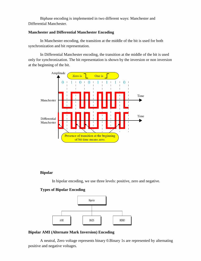
Biphase encoding is implemented in two different ways: Manchester and
Differential Manchester.
Manchester and Differential Manchester Encoding
In Manchester encoding, the transition at the middle of the bit is used for both
synchronization and bit representation.
In Differential Manchester encoding, the transition at the middle of the bit is used
only for synchronization. The bit representation is shown by the inversion or non inversion
at the beginning of the bit.
Bipolar
In bipolar encoding, we use three levels: positive, zero and negative.
Types of Bipolar Encoding
Bipolar AMI (Alternate Mark Inversion) Encoding
A neutral, Zero voltage represents binary 0.Binary 1s are represented by alternating
positive and negative voltages.

(Bipolar 8-Zero Substitution) B8ZS Encoding
In B8ZS if eight 0s come one after another, we change the pattern in one of two
ways based on the polarity of the previous 1.
(High-Density Bipolar 3) HDB3 Encoding
In HDB3 if four 0s come one after another, we change the pattern in one of four
ways based on the polarity of the previous 1 and the number of 1s since the last
substitution.
Example 5.1
Using B8ZS, encode the bit stream 10000000000100.Assume that the
polarity of the first 1 is positive.

Solution to Example 5.1
Example 5.2 Using HDB3, encode the bit stream 10000000000100.Assume that the
number of 1s so far is odd and the first 1 is positive.
Solution to Example 5.2
5.2 Analog to Digital Conversion
Pulse Amplitude Modulation (PAM)
The first step in analog to digital conversion is called Pulse Amplitude Modulation
(PAM).In PAM, the original signal is sampled at equal intervals.
Pulse Code Modulation (PCM)
PCM modifies the pulses created by PAM to create a completely digital signal.
Quantized PAM Signal

Quantization is a method of assigning integral values in a specific range to sampled
instances.

Quantizing Using Sign and Magnitude
Sampling Rate According to the Nyquist theorem, the sampling rate must be at least two times the
highest frequency.
PCM
From Analog signal to PCM digital code
Nyquist Theorem

5.3 Digital to Analog Conversion
This is the process of changing one of the characteristics of an Analog signal based
on the information in a digital signal (0s and 1s).
Type of Digital to Analog modulation

Aspect sof Digital to Analog conversion
Two basic issues must be define: bit/baud rate and carrie signal
Bitrate is the number of bits per second. Baud rate is the number of signal units per
second. baud rate is less than or equal to bit rate.
Amplitude Shift Keying (ASK)
In ASK the strengh of the carrier signal is varied to represent the binary 1 or 0. Both
frequency and phase remains constant, while the amplitude changes
A popular ASK technique is called on-off Keying (OOK) . In OOK one of the bit values
is represented by no voltage. Advantage is a reduction in the amount of energy required to
transmit information.
Bandwidth for ASK
Frequency Shift Keying (FSK)
In FSK the frequency of the carrier signal is varied to represent the binary 1 or 0. Both
Amplitude and phase remain constant, while the frequency changes. FSK avoids most of
the noise problems of PSK.

Bandwidth for FSK

Phase Shift Keying (PSK)
In PSK the phase of the carrier is varied to represent binary 1 or 0. Both peak amplitude
and frequency remains constant as the phase changes
The above method is often called 2-PSK or binary PSK, because two different phases (0
and 180 Degrees) are used
PSK Constellation
4-PSK
This Technique is also called Q-PSK . The pair of bits represented by each phase is
called a di bit. We can also extend this idea to 8-PSK. The constellation diagram for the
signal in shown in following figures:

4-PSK Characteristics
8 -PSK Characteristics
PSK Bandwidth
Quadrature Amplitude Modulation (QAM)

QAM means combining ASK and PSK in such a way that we have maximum contrast
between each bit, dibit, tribit, quadbit and so on. the following are the two possible
configuration :
4-QAM and 8-QAM Constellations
8-QAM Signal
16-QAM Constellation
Bit Rate and Baud Rate


Analog to Analog Conversion
Is the representation of analog information by an analog signal.
Types of Analog-to-analog modulation
Amplitude Modulation(AM)
AM Bandwidth

AM Band Allocation
Frequency Modulation(FM)
FM Bandwidth

FM Band Allocation
Phase Modulation(PM)
Due to simpler hardware requirements, phase modulation(PM) is used in some
systems as an alternative to frequency modulation.
Digital Data Transmission
Data transmission
Data needs to be transmitted between devices in a computer system.
Data is transmitted in the form of bits.
Data transmission refers to the movement of data in form of bits between two
or more digital devices.
DATA TRANSMISSION TYPES
1. Parallel
2. Serial
(i) Synchronous (ii) Asynchronous
PARALLEL TRANSMISSION
• In parallel transmission, all the bits of data are transmitted simultaneously on
separate communication lines.
• Parallel transmission is used for short distance communication.
• In order to transmit n bit , n wires or lines are used.

• More costly.
• Faster than serial transmission.
• Data can be transmitted in less time.
SERIAL TRANSMISSION
• In serial transmission , the various bits of data are transmitted serially one
after the other.
• It requires only one communication line rather than n lines to transmit data
from sender to receiver.
• Thus all the bits of data are transmitted
• on single lines in serial fashion.
• Less costly.
• Long distance transmission.
SYNCHRONOUS TRANSMISSION
• Data sent at one time multiple bytes.
• Start and stop bit not used.
• Gap between data units not present.
• Data transmission speed fast.
• Cost high.
• Transfer of data between two computer.
• Synchronization between sender and receiver required.
ASYNCHORONOUS TRANSMISSION
• Sends only one character at a time (one byte of data at a time)
• Synchronize two devices using Start Bit and Stop Bit.
• Start bit refers to the start of the data. Usually 0 is used for start bit.
• Stop bit indicates the end of data. More than one bit can be used for end.

Data Transmission
ParallelSerial
Cost
Speed
Transmission
Amount
Transmission
Lines
Transmission
Distance
Example
Cheap
Slow
Single bit
One line to transmit
one to receive
Long distance
Modem
Expensive
Fast
8 bits (8 data lines)
Transmitter & Receiver
8 lines for simultaneous
transmission
Short distance
(synchronization)
Printer Connection
ERRORS, DETECTION & CORRECTION
Errors in the data are basically caused due to the various impairments that occur during the
process of transmission.When there is an imperfect medium or environment exists in the
transmission it prone to errors in the original data.
Transmission errors are usually detected at the physical layer of the OSI model.
Transmission errors are usually corrected at the data link layer of the OSI model.
Types of Errors
Single-bit: In a single-bit error, only one bit in the data unit has changed.
Burst :A burst error means that two or more bits in the data unit have changed.

Single-bit error
Burst error
DETECTION
Redundancy-is one error detection mechanism. Redundancy is the concept of addition of
extra bits to a message for error detection. In order to detect and correct the errors in the data
communication we add some extra bits to the original data. These extra bits are nothing but
the redundant bits which will be removed by the receiver after receiving the data.
Their presence allows the receiver to detect or correct corrupted bits. Instead of repeating the
entire data stream, a short group of bits may be attached to the entire data stream.This
technique is called redundancy because the extra bits are redundant to the information:
they are discarded as soon as the accuracy of the transmission has been determined.
Fig: Redundancy
Four types of redundancy checks follows:
a)Vertical redundancy check(VRC)

b)Longitudinal redundancy check(LRC)
c)Cyclic redundancy check(CRC)
d)Checksum
Fig: Redundancy
Vertical redundancy check(VRC) In this technique, a redundant bit ,called a parity bit is added to every data unit so that the
total number of 1s becomes even.
Performance:VRC can detect only an odd numbers of errors; it cannot detect an even
number of errors.
Example: Imagine the sender wants to send the word "world.”
In ASCII the five characters are coded as
<--------1110111 1101111 1110010 1101100 1100100
w o r l d
Each of the first four characters has an even numbers of 1s,so the parity bit is a 0.The last
character(“d”),however, has three 1s(an odd number),so the parity bit is a 1 to make the
total number of 1s even. The following shows the actual bits sent(the parity bits are
underlined)
<-------11101110 11011110 11100100 11011000 11001001
w o r l d

Example: Now suppose the word “world” in the previous example is received by the
receiver but corrupted during transmission.
<------11111110 11011110 11101100 11011000 11001001
w o r l d
The receiver counts the 1s in each character and comes up with even and odd
numbers(7,6,5,4,4.)The receiver knows that the data are corrupted, discard them, and ask
for retransmission.
Longitudinal redundancy check(LRC)
In LRC,a block of bits is organized in a table(rows and columns)
For example, instead of sending a block of 32 bits, we organize them in a table made of
four rows and eight columns. We then calculate the parity bit for each column and create a
new row of eight bits.
Example: Suppose the following block is sent
<----- 10101001 00111001 11011101 11100111 10101010
(LRC)
However, it is hit by a burst noise of length eight and some bits are corrupted.
<----- 10100011 10001001 11011101 11100111 10101010
(LRC)
When the receiver checks the LRC,some of the bits do not follow the even-parity rule and
the whole block is discarded(the nonmatching bits are shown in bold.
<----- 10100011 10001001 11011101 11100111 10101010
(LRC)
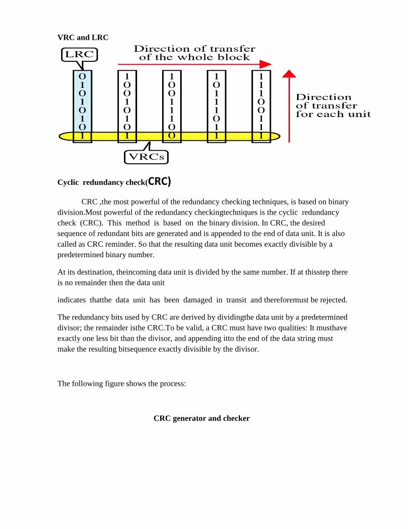
VRC and LRC
Cyclic redundancy check(CRC)
CRC ,the most powerful of the redundancy checking techniques, is based on binary
division.Most powerful of the redundancy checkingtechniques is the cyclic redundancy
check (CRC). This method is based on the binary division. In CRC, the desired
sequence of redundant bits are generated and is appended to the end of data unit. It is also
called as CRC reminder. So that the resulting data unit becomes exactly divisible by a
predetermined binary number.
At its destination, theincoming data unit is divided by the same number. If at thisstep there
is no remainder then the data unit
indicates thatthe data unit has been damaged in transit and thereforemust be rejected.
The redundancy bits used by CRC are derived by dividingthe data unit by a predetermined
divisor; the remainder isthe CRC.To be valid, a CRC must have two qualities: It musthave
exactly one less bit than the divisor, and appending itto the end of the data string must
make the resulting bitsequence exactly divisible by the divisor.
The following figure shows the process:
CRC generator and checker

Step1: A string of 0‘s is appended to the data unit. It is n bits long. The number n is 1 less if-
number of bits in the predetermined divisor which is n + 1 bits.
Step 2: The newly generated data unit is divided by the divisor, using a process called as
binary division. The remainder resulting from this division is the CRC.
Step 3: the CRC of n bits derived in step 2 replaces the appended 0‘s at the data unit. Note
that the CRC may consist of all 0‘s.
The data unit arrives at the receiver data first, followed by the CRC. The receiver treats the
whole string as a unit and divides it by the same divisor that was used the CRC remainder.
If the string arrives without error, the CRC checker yields a remainder of zero, the data unit
passes. If the string has been changed in transit, the division yields zero remainder and the
data unit does not pass.
A CRC checker functions does exactly as the generator does. After receiving the data
appended with the CRC, it does the samemodulo-2 division. If the remainder is all 0‘s, the

CRC isdropped and the data is accepted: otherwise, the receivedstream of bits is discarded
and data is resent.
Performance:
CRC is a very effective error detection method. If the divisoris chosen according to the
previously mentioned rules,
1.CRC can detect all burst errors that affect an odd numberof bits.
2.CRC can detect all burst errors of length less than or equalto the degree of the polynomial
3.CRC can detect, with a very high probability, burst errorsof length greater than the degree
of the polynomial.
Checksum
A checksum is fixed length data that is the result of performing certain operations on the data
to be sent from sender to the receiver. The sender runs the appropriate checksum algorithm
to compute the checksum of the data, appends it as a field in the packet that contains the
data to be sent, as well as various headers.
When the receiver receives the data, the receiver runs the same checksum algorithm to
compute a fresh checksum. The receiver compares this freshly computed checksum with
the checksum that was computed by the sender. If the two checksum matches, the receiver
of the data is assured that the data has not changed during the transit.
checksum is used by the higher-layer protocols(TCP/IP) for error detection.
To calculate a checksum:
a. Divide the data into sections.
b. Add the sections together using one's complement arithmetic.
c. Take the complement of the final sum; this is the checksum

Data Unit and Checksum

Error Correction
Data and Redundancy bits
Positions of redundancy bits in Hamming Code
The combinations used to calculate each of the four r values for a seven-bit data sequence
are as follows:
r1 : bits 1,3,5,7,9,11
r2 : bits 2,3,6,7,10,11
r3 : bits 4,5,6,7
r4 : bits 8,9,10,11
Redundancy bit calculation

Example of redundancy bit calculation


Single-bit error
Burst Error Detection
Hamming Code:
The Hamming code can be applied to data units of any length and uses the relationship
between data and redundancy bits discussed above. For example, a 7-bit ASCII code
requires 4 redundancy bits that can be added 10 the end of the data unit or interspersed
with the original data bits. In following Figure,these bits are placed in positions 1, 2,4, and
8 (the positions in an 11-bit sequence that are powers of 2). For clarity in the examples
below, we refer to these bits as r1, r2, r4, and r8.
11 10 9 8 7 6 5 4 3 2 1
d d d r8 d d d r4 d r2 r1
In the Hamming code, each r bit is the parity bit for onecombination of data bits, is shown below:

r1 : bits 1,3,5,7,9,11 r2 : bits 2,3,6,7,10,11 r3 : bits 4,5,6,7 r4 : bits 8,9,10,11
r1will be assigned to these bits position: 11 9 7 5 3
d d d r8 d d d r4 d r2 r1
1r2will be assigned to these bits position: 11 10 7 6 3 2
d d d r8 d d d r4 d r2 r1
r4will be assigned to these bits position: 7 6 5 4
d d d r8 d d d r4 d r2 r1
r8will be assigned to these bits position: 11 10 9 8
d d d r8 d d d r4 d r2 r1
Now suppose we have 1001101 data to be sent, then the redundant bits are calculated by the following method:
Data is: 1 0 0 1 1 0 1
11 10 9 8 7 6 5 4 3 2 1
1 0 0 1 1 0 1
Adding r1: 11 10 9 8 7 6 5 4 3 2 1
1 0 0 1 1 0 1 1
Adding r2: 11 10 9 8 7 6 5 4 3 2 1
1 0 0 1 1 0 1 0 1
Adding r4:

11 10 9 8 7 6 5 4 3 2 1
1 0 0 1 1 0 0 1 0 1
Adding r8: 11 10 9 8 7 6 5 4 3 2 1
1 0 0 1 1 1 0 0 1 0 1
Code: 10011100101 Now imagine that by the time the above transmission isreceived, the number 7 bit has been
changed from 1 to 0.The receiver takes the transmission and recalculates 4 newparity bits,
using the same sets of bits used by the senderplus the relevant parity r bit for each set (see
following Fig.). Thenit assembles the new parity values into a binary number inorder of r
position (r8 r4, r2, r1). In our example, this stepgives us the binary number 0111 (7 in
decimal), which is theprecise location of the bit in error.
Corrupted bit
1 0 0 1 0 1 0 0 1 0 1
1 0 0 1 0 1 0 0 1 0 1
1 0 0 1 0 1 0 0 1 0 1
1 0 0 1 0 1 0 0 1 0 1
Error bit position 7 : 01 1 1 Once the bit is identified, the receiver can reverse itsvalue and correct the error. The beauty
of the technique isthat it can easily be implemented in hardware and the codeis corrected
before the receiver knows about it.

Polynomial
Polynomial and Divisor
Standard Polynomials
TRANSMISSION MODES
Data is transmitted between two digital devices on the network in the form of bits.
Transmission mode refers to the mode used for transmitting the data. The transmission
medium may be capable of sending only a single bit in unit time or multiple bits in unit time
When a single bit is transmitted in unit time the transmission mode used is Serial
Transmission and when multiple bits are sent in unit time the transmission mode used
is called Parallel transmission.
Types of Transmission Modes:
There are two basic types of transmission modes Serial and Parallel as shown in the
figure below.
Serial transmission is further categorized into Synchronous and
Asynchronous Serial transmission.

Fig. Types of Transmission Modes Parallel Transmission
It involves simultaneous transmission of N bits over N different channels Parallel
Transmission increases transmission speed by a factor of N over serial transmission
Disadvantage of parallel transmission is the cost involved, N channels have to be used,
hence, it can be used for short distance communication only.
Fig. Parallel Transmission of Data over N = 8 channels
Example of Parallel Transmission is the communication between CPU and the
Projector.
Serial Transmission
In Serial Transmission, as the name suggests data is transmitted serially, i.e. bit by
bit, one bit at a time. Since only one bit has to be sent in unit time only a single channel is
required.

Fig. Serial Transmission of Data over N = 8 channels
Types of Serial Transmission:
Depending upon the timing of transmission of data there are two types of serial transmission
as described below
ASynchronous Transmission
In asynchronous serial transmission the sender and receiver are not synchronized.The data
is sent in group of 8 bits i.e. in bytes. The sender can start data transmission at any time
instant without informing the receiver. To avoid confusing the receiver while receiving the
data, ―start‖ and ―stop‖ bits are inserted before and after every
group of 8 bits as shown below
0 1 BYTE 1
Fig: Start and Bit before and after every data byte
The start bit is indicated by0‖ and stop bit is indicated by1‖. The sender and receiver may
not be synchronized as seen above but at the bit level they have to be synchronized i.e. the
duration of one bit needs to be same for both sender and receiver for accurate data
transmission. There may be gaps in between the data transmission indication that there
is no data being transmitted from sender. Ex. Assume a user typing at uneven speeds,
attimes there is no data being transmitted from Keyboard to the CPU.Following is
the Diagram for Asynchronous Serial
Transmission.
Fig: Asynchronous Serial Transmission

Advantages 1. Cheap and Effective implementation 2. Can be used for low speed communication
Disadvantages Insertion of start bits, stop bits and gaps make asynchronous transmission slow.
Application Keyboard
Synchronous Transmission
In Synchronous Serial Transmission, the sender and receiver are highly
synchronized.No start, stop bits are used. Instead a common master clock is used for
reference. The sender simply send stream of data bits in group of 8 bits to the receiver without
any start or stop bit. It is the responsibility of the receiver to regroup the bits into units of 8
bits once they are received.When no data is being transmitted a sequence of 0‘s and 1‘s
indicating IDLE is put on the transmission medium by the sender.
Fig: Asynchronous Serial Transmission
Advantage 1. There are no start bits, stop bits or gaps between data
units 2. Since the above are absent data transmission is
faster. 3. Due to synchronization there are no timing errors.

9.2.2.3 Comparison of serial and parallel transmission
Sr.no Parameter Parallel transmission
Serial transmission
1 Number of wire required to transmit N bits
N wire 1 wire
2 Number of bits transmitted simultaneously
N bits 1 bit
3 Speed of data transfer
False Slow
4 Cost Higher due to more number of conductor
Low, since only one wire is used
5 Application Short distance communication such as computer to printer communication
Long distance computer to computer communication.
Data-Link Protocols
Data-Link Protocol Functions
Line discipline – coordinates hop-to-hop data delivery where a hop is a computer, a
network controller, or some type of network-connecting device, such as router
It determines which device is transmitting and which is receiving at any point in time
Flow control – the rate at which data is transported over a link
--provides an acknowledgement mechanism that data is received at the destination
--regulate flow of data from sender to receiver
Error control – detects and corrects transmission errors
Framing – recognizing beginning and end of frames (blocks, packets)

Communications requires at least two devices, one to send and one to receive. If both
devices are ready to send some information and put their signals on the link then the two
signals collides each other and became nothing. To avoid such a situation the data link
layer use a mechanism called line discipline.
Line discipline coordinates the link system. It determines which device can send and
when it can send. It answers then question, who should send now?
Line discipline can serve in two ways:
1. enquiry / acknowledgement (ENQ / ACK)
2. poll / select (POLL / SELECT)
ENQ / ACK:
This method is used in peer to peer communications. That is where there is a dedicated
link between two devices. The initiator first transmits a frame called an enquiry (ENQ)
asking I the receiver is available to receive data. The receiver must answer either with an
acknowledgement (ACK) frame if it ready to accept or with a negative acknowledgement
(NAK) frame if it is not ready. If the response is positive, the initiator is free to send its
data. Otherwise it waits, and try again. Once all its data have been transmitted, the
sending system finishes with an end of transmission (EOT) frame.Line discipline
Example of ENQ/ACK line discipline
POLL/SELECT:

Example of poll/select line discipline
Flow control
Stop-and-Wait flow control
• Source transmits frame • Destination receives frame and replies with acknowledgement • Source waits for ACK before sending next frame • Destination can stop flow by not send ACK • Works well for a few large frames

Example of Stop-and-Wait flow control
Sliding Window flow control
Error Control
Detection and correction of errors
Lost frames
Damaged frames
Techniques for error control (Automatic repeat request)
--Error detection
--Positive acknowledgment
--Retransmission after timeout
--Negative acknowledgement and retransmission

FLOW CONTROL AND ERROR CONTROL
FLOW CONTROL
It refers to a set of procedures used to restrict the amount of data flow between
sending and receiving stations. It tells the sender how much data it can transmit before it
must wait for an acknowledgement from the receiver. There are two methods are used. They are,
1. stop and wait
2. sliding window
STOP AND WAIT:
In this method the sender waits for acknowledgment after every frame it sends.
Only after an acknowledgment has been received, then the sender sends the next frame.

The advantage is simplicity. The disadvantage is inefficiencySLIDING
WINDOW:
In this method, the sender can transmit several frames before needing an
acknowledgment. The receiver acknowledges only some of the frames, using a single ACK
to confirm the receipt of multiple data frames.
The sliding window refers to imaginary boxes at both the sender and receiver. This
window provides the upper limit on the number of frames that can be transmitted before
requiring an acknowledgement. To identify each frame the sliding window scheme
introduces the sequence number. The frames are numbered as 0 to n-1. And the size of the
window is n-1. Here the size of the window is 7 and the frames are numbered as
0,1,2,3,4,5,6,7.
SENDER WINDOW:
At the beginning the sender‟s window contains n-1 frames. As frames are sent
out the left boundary of the window moves inward, shrinking the size of the window.
Once an ACK receives the window expands at the right side boundary to allow in a
number of new frames equal to number of frames acknowledged by that ACK.

EXAMPLE:
ERROR CONTROL
Error control is implemented in such a way that every time an error is detected, a
negative acknowledgement is returned and the specified frame is retransmitted. This
process is called automatic repeat request (ARQ).
The error control is implemented with the flow control mechanism. So there are

two types in error control. They are,
1. stop and wait ARQ
2. sliding window ARQ
STOP AND WAIT ARQ:
It is a form of stop and wait flow control, extended to include retransmission of
data in case of lost or damaged frames.

DAMAGED FRAME:
When a frame is discovered by the receiver to contain an error, it returns a
NAK frame and the sender retransmits the last frame.
LOST DATA FRAME:
The sender is equipped with a timer that starts every time a data frame is
transmitted. If the frame lost in transmission the receiver can never acknowledge it. The
sending device waits for an ACK or NAK frame until its timer goes off, then it tries again.
It retransmits the last data frame.

LOST ACKNOWLEDGEMENT:
The data frame was received by the receiver but the acknowledgement was lost in
transmission. The sender waits until the timer goes off, then it retransmits the data frame.
The receiver gets a duplicated copy of the data frame. So it knows the acknowledgement
was lost so it discards the second copy.
SLIDING WINDOW ARQ
It is used to send multiple frames per time. The number of frame is according to the
window size. The sliding window is an imaginary box which is reside on both sender and
receiver side.
It has two types. They are,
1. go-back-n ARQ
2. selective reject ARQ
GO-BACK-N ARQ:
In this method, if one frame is lost or damaged, all frames sent since the last
frame acknowledged or retransmitted.
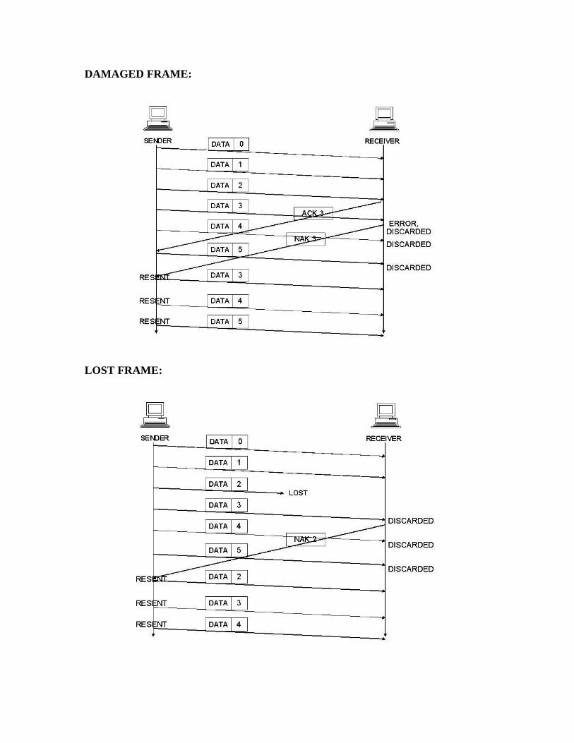
DAMAGED FRAME: LOST FRAME:
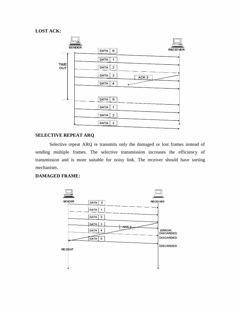
LOST ACK: SELECTIVE REPEAT ARQ
Selective repeat ARQ re transmits only the damaged or lost frames instead of
sending multiple frames. The selective transmission increases the efficiency of
transmission and is more suitable for noisy link. The receiver should have sorting
mechanism. DAMAGED FRAME:

LOST FRAME LOST ACK
------------------------------------------------------------------------------------------------------------

1. What do you mean by Automatic Repeat Request (ARQ)?
ARQ means retransmission of data in three cases:
Damaged Frame
Lost Frame
Lost Acknowledge
2. What are the responsibilities of Data Link Layer?
The Data Link Layer transforms the physical layer, a raw transmission facility, to a
reliable link and is responsible for node-node delivery.
Framing
Physical Addressing
Flow Control
Error Control
Access Control
3. What are the three protocols used for noisy channels?
The three protocols used for noisy channels
Stop – and – Wait ARQ
Go – back – N ARQ
Selective Repeat ARQ
4. What is CSMA/CD?
Carrier Sense Multiple Access with Collision Detection is a protocol used to sense
whether a medium is busy before transmission and it also has the ability to detect whether
the packets has collided with another
5. What are the various types of connecting devices?
There are five types of connecting devices
Repeaters
Hubs
Bridges
Routers
Switches.

6. Define Flow control
It refers to a set of procedures used to restrict the amount of data the sender
can sent before waiting for an acknowledgement
7. What are the categories of Flow control?
The categories of Flow control are
Stop& wait
Sliding Window
8. Mention the disadvantages of stop& wait.
Inefficiency
Slow process
9. What are the functions of data link layer?
The functions of data link layer are
Flow control
Error control
10. Define Link Discipline
send.
It coordinates the link system. It determines which device can send and when it can
11. What do you mean by polling?
When the primary device is ready to receive data, it asks the secondary to send data.
This is called polling.
12.What are the various controlled access methods?
The various controlled access methods are
Reservation
Token passing
Polling
13 What are the various Random access methods?\
The various Random access methods are
Slotted ALOHA
CSMA
CSMA/CD,CSMA/CA

14. Define Piconet
A Bluetooth network is called Piconet .It can have up to eight stations one of which is
called the master and the rest are called slaves,
15. What is the frequency range of Bluetooth devices?
The frequency range of Bluetooth device is 2.4 GHZ
16. What is the need of connecting devices?
To connect LANs or segments of LAN we use connecting devices. These devices
can operate in different layers of internet model.
17. What type of address a data link layer is using?
The data link layer is using a physical address
18. What do you mean by Backbone networks?
It allows several LANs to be connected. The architecture used are Star and Bus
19. What is the need of frame relay?
It is a Virtual circuit wide area network that was designed to respond to demands
for a new type of WAN.
20. What is the maximum length of a datagram?
The maximum length of a datagram is 65,535 bytes.
21. What are the key functions of error control techniques?
Ans: There are basically two types of errors, namely, (a) Damaged Frame (b) Lost Frame. The key
functions for error control techniques are as follows:
Error detection
Sending of positive acknowledgement (ACK) by the receiver for no error
Sending of negative acknowledgement (NAK) by the receiver for error
Setting of timer for lost frame
Numbering of frames
22. Why is flow control needed?
Ans: In case of data communication between a sender and a receiver, it may so happen that the rate
at which data is transmitted by a fast sender is not acceptable by a slow receiver. IN such a situation,
there is a need of flow control so that a fast transmitter does not overwhelm a slow receiver.

23. Mention key advantages and disadvantages of stop-and-wait ARQ technique?
Ans: Advantages of stop-and-wait ARQ are:
a. Simple to implement
b. Frame numbering is modulo-2, i.e. only 1 bit is required.
The main disadvantage of stop-and-wait ARQ is that when the propagation delay is long, it is extremely
inefficient.
24. Consider the use of 10 K-bit size frames on a 10 Mbps satellite channel with 270 ms delay.
What is the link utilization for stop-and-wait ARQ technique assuming P = 10-3?
Ans: Link utilization = (1-P) / (1+2a)
Where a = (Propagation Time) / (Transmission Time)
Propagation time = 270 msec
Transmission time = (frame length) / (data rate)
= (10 K-bit) / (10 Mbps)
= 1 msec
Hence, a = 270/1 = 270
Link utilization = 0.999/(1+2*270) ≈0.0018 =0.18%
25. What is the channel utilization for the go-back-N protocol with window size of 7 for the
problem 3? Ans: Channel utilization for go-back-N
= N(1 – P) / (1 + 2a)(1-P+NP)
P = probability of single frame error ≈ 10-3
Channel utilization ≈ 0.01285 = 1.285%
26. In what way selective-repeat is better than go-back-N ARQ technique? Ans : In selective-repeat scheme only the frame in error is retransmitted rather than transmitting all
the subsequent frames. Hence it is more efficient than go-back-N ARQ technique.
27. In what situation Stop-and-Wait protocol works efficiently?
Ans: In case of Stop-and-Wait protocol, the transmitter after sending a frame waits for the
acknowledgement from the receiver before sending the next frame. This protocol works efficiently
for long frames, where propagation time is small compared to the transmission time of the frame.
28. How the inefficiency of Stop-and-Wait protocol is overcome in sliding window protocol?
Ans: The Stop-and-Wait protocol is inefficient when large numbers of small packets are send by the
transmitter since the transmitter has to wait for the acknowledgement of each individual packet
before sending the next one. This problem can be overcome by sliding window protocol. In sliding
window protocol multiple frames (up to a fixed number of frames) are send before receiving an
acknowledgement from the receiver.
30. What is piggybacking? What is its advantage?

Ans: In practice, the link between receiver and transmitter is full duplex and usually both transmitter
and receiver stations send data to each over. So, instead of sending separate acknowledgement
packets, a portion (few bits) of the data frames can be used for acknowledgement. This phenomenon
is known as piggybacking.
The piggybacking helps in better channel utilization. Further, multi-frame acknowledgement can be
done.
31. For a k-bit numbering scheme, what is the range of sequence numbers used in sliding
window protocol?
Ans: For k-bit numbering scheme, the total number of frames, N, in the sliding window can be given
as follows (using modulo-k).
N = 2k – 1
Hence the range of sequence numbers is: 0, 1, 2, and 3 … 2k – 1
Version
32. Why do you need error detection?
Ans: As the signal is transmitted through a media, the signal gets corrupted because of noise and
distortion. In other words, the media is not reliable. To achieve a reliable communication through this
unreliable media, there is need for detecting the error in the signal so that suitable mechanism can be
devised to take corrective actions.
33. How does NRZ-L differ from NRZ-I?
In the NRZ-L sequence, positive and negative voltages have specific meanings: positive for 0 and
negative for 1. in the NRZ-I sequence, the voltages are meaningless.
Instead, the receiver looks for changes from one level to another as its basis for recognition of 1s.
34. What are the responsibilities of data link layer?
Specific responsibilities of data link layer include the following. a) Framing b) Physical addressing
c) Flow control d) Error control e) Access control.
35. What are the ways to address the framing problem?
Byte-Oriented Protocols(PPP)
Bit-Oriented Protocols(HDLC)
Clock-Based Framing(SONET) 36.What is the purpose of hamming code?

A hamming code can be designed to correct burst errors of certain lengths. So the simple
strategy used by the hamming code to correct single bit errors must be redesigned to be
applicable for multiple bit correction.
37.What is redundancy?
It is the error detecting mechanism, which means a shorter group of bits or extra bits may be
appended at the destination of each unit.
38.Define flow control?
Flow control refers to a set of procedures used to restrict the amount of data. The sender can
send before waiting for acknowledgment.
39.Mention the categories of flow control? There are 2 methods have been developed to control flow of data across communication links. a) Stop
and wait- send one from at a time. b) Sliding window- send several frames at a time.
40.What is a buffer?
Each receiving device has a block of memory called a buffer, reserved for storing incoming data
until they are processed.