unclassified - defense technical information center database approach to communication in vlsi...
TRANSCRIPT

UNCLASSIFIEDSECURITY CLASSIFICATION OF T" S PAGE (When 7r'. Enttemd)
REPORTREAD INSTRUCTIONS_____ REPORT___DOCUMENTATION ____PAGE BEFORE COMPLETING FORM
1. REPORT NUMBER 2. GOVT ACCESSION NO 3. RECIPIENT'S CATALOG NUMBER
STAN-CS-80-826 V4. TITLE (end Subtitle) TYPE OF REPORT & PERIOD COVERED
A DATABASE APPROACH TO COMMUNICATION INVLSI DESIGN
6. PERFORMING ORG. REPORT NUMBER
. 17. AUTHOR(s) 6. CONTRACT OR GRANT NUMBER(@)
Gio Wiederhold, Anne Beetem, Garrett Short N3980C0132
9. PERFORMING ORGANIZATION NAME AND ADDRESS 10. PROGRAM ELEMENT. PROJECT, TASK
Stanford University AREA & WORK UNIT NUMBERS
Department of Computer Science
AO 3889
11. CONTROLLING OFFICE NAME AND ADDRESS 12. REPORT DATEOct 1980
Defense Advanced Research Projects Agency 13. NUMBEROFPAGES
1400 Wilson Blvd., Arlington, VA 22209 14
14. MONITORING AGENCY NAME & ADDRESS(If different from Controlling Office) 15. SECURITY CLASS. (of this report)
NESC UnclassifiedIS. DECLASSI FICATION/DOWNGRADING
SCHEDULE
16. DISTRIBUTION STATEMENT (of this Report)
APPROVED FOR PUBLIC RELEASE. DISTRIBUTION UNLIMITED
17. DISTRIBUTION STATEMENT (of the abstract entered in Block 20, If different from Report)
IS. SUPPLEMENTARY NOTES
19. KEY WORDS (Continue on reverse aide if nocesaary and identify by block number)
Database Commercial databases
Communication Macro Expansion
Hierarchial DesignDBMS-20Engineering Change Orders
20. ABSTRACT (Continue an reverse sideF It necessary arnd Identify by block Maribor)
(U)-This paper describes recent and planned work at Stanford in applying database technology to
the problems of" VI.SI design. In particular, it addresses the issue of communication within adesign's different representations and hierarchical levels in a multiple designer environment. We
demonstrate the heretofore questioned utility of using commercial database systems, at least whiledeveloping a versatile, flexible, and generally efficient model and its associated communicationpaths. Completed work and results from initial work using DEC DBMS-20 is presented, includingmacro expansion within the database, and signalling of changes to higher structural levels.Considerable discussion regarding overall philosophy for continued work is also included. 4,
DO I FA%" 1473 EOTIO Of NOV 65 S OSOLEE UNCLASSIFIED
SECURITY CLASSIFICATION OF THIS PAGE (Wen Data tngtered)


A Database Approach to Communication in VLSI Design
Gio Wiederhold, Anne Beetem, and Garrett ShortStunford University
Dept. ofComnputer ScienceOctober, 1980
1. Introduction
The design of a VLSI device involves the manipulation of a large Volume of diverse intcrrclated
data. For a given design task, such as simulation or layout, some data may be generated through
either computation or through recording of interactively made human designer decisions. In current
design methodologies, these design tasks operate on different representational levels of the same
device, ranging from overall functional or logical descriptions 11il1180i down to the physics of
individual s'-.itching cells. A single task may carry out verification within one level, may generate
lower level units by expansion of more abstract definitions, or otherwise necessitate movement
between different representational levels. In addition, if complex designs are to be produced in a
tolerable time frame, then several design specialists must be allowed to work concurrently on
distinct sections or at distinct levels. All this causes the management of the design data to become
increasingly difficult since not only will data requirements overlap, but one design task will often be
dependent on the data being manipulated in another area. This data communication effort probably
contributes significantly to the increase in effort from 4 to 30 man-years for microprocessor designs,
and makes single-designer oriented methodologies infeasible [Sch791. The exponential growth of
design cost while production costs diminish - as stated by -aggin and Moore in IRoh)801 - is
changing the outlook of the microprocessor industry, pointing to the need for more effective
handling of design data.
)atabase technology has dealt with both the management of large volumes of data and the
problems caused by concurrency of data access. Many existing database systems support inter-area
communication functions; instances are found of systems dealing with inventories, where productionand sales issues interface, or patient management, where individual care and global health care
concerns come together. Databases are used as well to resolve the multidisciplinary design issues in
aircraft design [Ft,180 and to manage die problems of engineering changes in computing systems
[Sie8O]. Given this background, we foresee that databases may provide tools to serve the VI.SI
designers; however, the tool is complex and will not be effective unless well understood and
adapted to the demands of this application.
We have identified several issues that have to be addressed if databases are to become el'fective
tools in VLSI design. (The interested reader may wish to compare these to 1I.ey79] which has a
somewhat different approach.)
IIIIIIIIIII-011.

-r
2
1.) The database system must support a variety of design methodologies. The support of a top-
down approach is most easily achieved, but processes at a lower levcl may contribute information to
higher levels. Also, a designcr may necd to make changes at any lcvcl, which have to be reflected
throughout the design levels. An example of the first exception to a pure top-down method is thehandling of timing data than can be produced only after a detailed layout is available, while gateshave been dimensioned using simple assumptions of intergate transit times. A second case arises
when a particular gate of a series is changed to satisfy special interface demands or terminating
conditions.
2.) I:xplicit storage for all attributes of all elements at lower levels must be avoided in order to
permit effective management of change emanating at a higher level. Excessive replication of lowerlevel elements vitiates the benefits of hierarchical design methods, and creates excessive storagedemands. '[his implies that the database system must be able to fetch actually instantiated data orcon)u1te potential, non-instantiated data using stored algorithms.
3.) The database must be able to provide a convenient interface to a wide and changing variety ofprograms. [his interface should not change as the database is developed and extended.
4.) The performance of the database system has to be such that the degradation of performancerelative to an isolated design file operation is proportional to the benefits gained.
IL. \lp roach
[he approach we are using in OUr work includes the use of commercial database systems to;te ." the general suitability of database approaches to-VI.Sl design data. One objective is todcterlmine whether commercial database systems, used knowledgeably , can perform adequately, orit they do not, where the bottlenecks arc. The current set of experiments uses a network system,
)1'( "s I)IMS-20. This is a system based on the published COI)ASYi database definition, which
hmsa ,trong orientation to well-understood business applications, such as inventory management.'lhe dalabase designer can, through schema specification, select which of the logically appropriatelinkages should be implemented [WFM80J. As a successor experiment in this area we plan toinVestigate use of a relational database system, RIMS, with strong automatic query optimiation
c;ip.hilitics [Sire80].
After having demonstrated replacement of a custom design by an equivalent database
rWpresenltaion, we explored implementation of novel data management facilities not provided byspeciali/cd design files. Specifically, as is necessary in order to operate in the mode for die VILSIdesign enviromnent, the database system has to be augmented with communication paths between
Ice ls. These paths may ultimately be oriented in any combination of directions. We areinc,;tig.ting the constituent directions, viz. down hierarchical level, up to higher level units, and
sidcways.
1

3
In the downward direction, a method must exist to create the effect of lower level instantiation
using procedures and higher level descriptions. It is desirable that the query interfaces which accessthe lower levels do not have to distinguish between actual or computed data elements. Along these
same lines, we intend to look at the issues and possibilities of when and how we wish to storeredundant or computed data.
Communication in the upward direction relates detail to more abstract specifications. 'lle
creation or modification of lower level instances has to be bound to the appropriate higher level
elements. An initial approach we consider promising and have implemented is signalling suchchanges to the next levels up in the hierarchy. Multiple structures may become involved I)ecause anelement may be defined by an association of several higher level entities [Wic771: a simple exampleis an element that is defined from the expansion of a functional component and a librarydescription. The signal creates an exception flag at tile higher structures. At a later time, when thelevel to which the signal was directed is acc. -d by its owner, the system can provide a 'arning.An appropriate action could then be taken; for example, verification of continued correctness of thedesign at that level, or the introduction of a new version of :" component, or a new parameterizationof the library descriptions. With experience, selected types of changes could trigger automaticupdates.
While the need and techniques for up and down passing of information are relatively clear,travel in the orthogonal direction is not nearly so, yet may be essential in the Future design system.To explain the need consider the following scenario. Suppose we are designing a microcomputer
chip with an Al.U composed primarily of registers , dense RAM and ROM, a finite state PI.Acontroller, some random logic, etc. l)esigning this chip with only one methodology would be a.
terrific waste of time and energy as, although there are design tools which can fairly efficientlymodel, for example, random logic, it would v'ery inefficient to design a regular structure like aPLA using random logic techniques. It would be far More efetctive to allow a sub-module to bedesigned or simulated in its most appropriate manlier. Allowing for generalized sideways
communication could then greatly increase the overall flexibility and efficiency of a design system.
Current working design systems give no consideration to this sideways communication issue, but theresearch has begun (see [Be801 for example) . We hope to learn from it and incorporate these new
ideas into our database system.
III. Current Work and Results
Before we to discuss what actual work we have done, it must be noted that due to availability
of data, programs, and otherwise existing material at hand, we are using data from conventional
circuit board design to model the VLSI design process. Iven so, man) of the problems are similarand as such, we believe that the results are validly applicable to the VI.SI design process as well.More importantly, by using this data, we were able to mike benchmark compairisons with existing
8*

4
specialized design files and programs on the same data. This is essential for measuring the relative
performance of commercial database systems. We feel that we have gained insight into the problems
involved in a database oriented design system, and in particular, have demonstrated the viability and
efficiency of using commercial database systems at least until the complete model of the design
process and its communication requirements is well understood. So, without further ado let us
describe exactly what we have done so far.
Reading from a Database
First, an evalution was made of )EC's l)lBMS-20 performance on data retrieval times.
Specialized design files of circuit information were used as the control to the experiment. The userbegins with his design written in SI)i. (Structural Design L.anguage JvC791 ), a straightforward
hierarchical description language. The SDI. de,;cription is input to the SI)I. compiler, which then
produces a dump file containing the logical description of each component decribed in the design.'[his design methodogy is strictly hierarchical: the logical description of one component is described
in terms of smaller lower level components. [or example, gates arc described in terms of transistors,
flip-flops arc described in term of gates, registers arc described in terms of flip-flops, etc. Each
description level is given an unique name in the design file. Figure 1 shows the hierarchical
structure of the Pl)l-I 1 processor, as described in SDI. [SI.79]. The dump file from the compiler isloaded into the SPRINT database [Ste79], the specialized control subject, via a 'hardwired' schema.
L.evel ('omponents
cpu PI)P- I 1reg BLI.EG, PROCOUNT, BUSCOUNI', RAM16XI6, ALU, STATUS, AMUX
rfl PRIOARB. TIMER
rf2 TCFF2, RAMI6. 40181, 40182
ff TCFF, 1.116, I)1T4, IIUSI)I6, MUX16, RAMgate 1)1'1", [f:F XOR, lluSI), MUX
trans TRANSP, INV, NANI), 3NANI), 4NANI), NOR, 3NOR, 4NOR
bottom TN, TP, PLA-SMAI.., PIA-MEI), PLA-LARGE
Figure 1
Initially the COI)ASYI. schema was modeled very closely to the SPRINT schema, and due to
SIRIN'I"s hierarchical structure, COI)ASYI. network capabilities were not utilized in the firstiteration. later the schema was modified to take advantage of network structures: this effort
provided linked access to the library file of componenis. A loader program was then written to load
the same dump file produced by the SI)I. compiler into the l)IIMS-20 database. Comparison of
loading times showed the SPRINT database to bc quicker, as expected, but I)BMS times were quite

acceptable. The initial loading of the PDP-11 example took SPRINT about one minute andrequired about four minutes for I)BMS-20.
For the actual test of the retrieval times, a macroexpander program [Pay80] was used. Thisprogram reads the logical description of a high level component from the database. 'The user thenspecifies the levels to be expanded. Thus, if the user specified the program to expand all levelsdown to the trar.;istor, then the resulting output will be the logical description of the originalcomponent described totally in terms of transistors. This form of description may not be very usefulto the designer, but could be the input to, for example, a simulator program. Also, in the VLSIenvironment, this could be the first step in producing the layout diagram.
The macroexpander program needs to do a tremendous amount of random read operations,especially if the component that is being expanded is large and described at a high level. Thefollowing are the results of expanding the AI.U and the PDII-11:
SPRINT DB S-20 records read words read
ALU 10 time 21 s 33 s 1514 7754
CPU time 30 45
POP-lI 10 time 66 115 5925 2850!
CPU time 120 190
'Iliese results show less than a factor of two degradation in performance of the I)BMS-20. This is anacceptable trade-off for the increased flexibility and generality of COI)ASYI., and disputes theoriginal theories that there would be at least an order of magnitude difference in performance.
Writing into the DatabaseWe next evaluated DBMS-20 performance in writing back into the database. In order to
simulate a real application of VLSI design, we considered how the database would handleinstantiations. Seeing how this might be done requires a closer look at the schema. Figure 2 showsa subset of the network diagram of the schema. This is a version of the SPRINT schema, with a fewchanges to more closely model VLSI design. For each component dscribed in the database there isa ILogical I)escription record containing its name. This field is used as the key to find the recorddirectly via a hashing function. Records are connected to related records through three distinctrings of pointers, forming a complex network. One of the rings off of the Logical I)escriptionrecord describes each external pin, with a unique name and its function (i.e. input, output, tristate).The equivalent-group ring describes the equivalence bhtween pins and sets of pins. The remainingring off of the logical description record supplies the internal description of the part. For eachInternal )escription record, a General Information record is kept describing general characteristics.The attribute fields, creator, a time stamp, level, purpose, and version number are meant to fully

Logical Description
Equivalent-groups
! __ InameLogical Pin type
name
type
Equivalent-Elements
elementInternal Description type
General Information Net Componentcreator name nametime - I logical type
level external
purposeverson -vcomponent
pin net
E pin
Figure 2
l ,, , 9_ _ _ _ _ _ _ _ - -- ~

6
describe the corresponding internal description.
In order to exercise the representation, the macroexpandcr program was modified so that itcould write back into the database. When working in this mode, after the program expands a
component, it stores the new representation as another internal description along with a generalinformation record with the appropriate data. In the design atmosphere, suppose one is working on
a component at another level or perhaps at the same levol. The user makes some changes from theoriginal description and stores his version into the database. This may be done to several or all thecomponents. Now when a higher level componcnt is expanded, the program can selectively choose
the appropriate internal description to use. The above scenario was tested on the AlU with
following results:
upper level desription of the A[U contains the following pieces and levels:40181 rf240181 rf2
MUX gateXOR gateINV transNAND trans4NANI) trans
NOR trans4NOR trans
The following is some of the data on expanding the pieces of the ALU:
40181: Total read time = 17.4 seconds.record name quantity
net 152component 127
comp-pin 564Total read 843 (4432 words)
Total write time = 41.3 seconds.
record name quantitynet 154
net-pin 898
component 293
comp-pin 898Total written 2243 (10136 words)
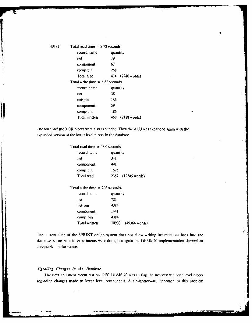
40182: Total read time = 8.78 seconds
record name quantity
Pet 79
component 67
comp-pin 268Total read 414 (2240 words)
Total write time = 8.82 seconds
record name quantity
net 38
net-pin 186
component 59
comp-pin 186
Total written 469 (2128 words)
'lhe nioix anO the XOR pieces were also expanded. Then the A[U was expanded again with the
expanded 'ersion of the lower level pieces in the database.
lotal read time = 48.0 seconds.record name quantity
net 341
component 441
comp-pin 1575lotal read 2357 (12745 words)
Total write time = 203 seconds.
record name quantity
net 721net-pin 4384
component 1441
comp-pin 4384
Total written 10930 (49364 words)
[he eni ient state of the SPRINT design system does not allow writing instantiations back into the
d~la~ii,,c, so no parallel experiments were done, but again the )IBMS-20 implementation showed an
,iccepi~ihk lerforniance.
Signalling Changes in the DatabaseThe next and most recent test on I)C )I)MS-20 was to flag the neccessary upper level pieces
regarding changes made to lower level components. A straightforward approach to this problem
I .. . .. ,. ... - .'T- - - - ... -ii lrI"-::' ="-
' ' ""

would be to have each component keep track of the upper level parts that use that component. To
implement this in CODASYL, we would like to have each Logical Description record own other
Logical Description records in a owners set, as such:
Logical Description ownersname linksetchanged
Besides causing cyclic errors, this structure is not allowed in the COl)ASYi. definition. The
technique used was to add another record off the logical description to indirectly find the owners,
illustrated below.
ILogical Description
namechanged
pieces ownerslinkset linkset
PointerBox
marked
The following example illustrates how upper level pieces are warned of lower level changes.
Suppose the multiplexer (MUX) has been changed and we wish to flag all the components that use
the multiplexer. In the database there are several parts that use the multiplexer, and for each one of
these there is a PointerBox record in the multiplexer's ow¥ners linkset. Some of these include the
ALU, status register, and a 16-input multiplexer (MUX16), see figure 1. These same PointerBox
records are in the pieces linkset of the parts that use the multiplexer. The multiplexer itself is made
up of inverters and transistor pairs (TRANSP). Thus there are two PointerBox records in the pieces
linkset of the multiplexer. The flagging process begins by marking the first record of the ownerslinkset, in this case say it is the ALU. Here the field marked of the PointerBox is incremented.
Next. the owner record of the pieces linksct of the current PointcrBox is found. lach Pointerliox
record has a pointer directly to the owner record of both the pieces linkset and the owners linkset.
At this time, the logical description record of the Al U is located and the field change is
incremented. Flagging continues from the Al.U in a recursive manner. When a logical descriptionrecord with a empty owners linkset is found, the upper most level has been reached. The flagging
must then move back to the previous level by finding the next PointcerBox record of the owners
linkset.
Ib
9
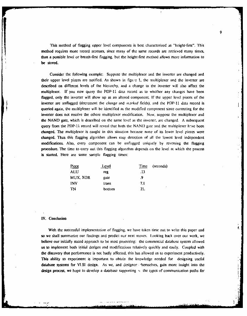
"is method of flagging upper level components is best characterized as "height-first". Ibismethod requires more record accesses, since many of the same records are retrieved many times,than a possible level or breath-first flagging, but the height-first method allows more information to
be stored.
Consider the following example: Suppose the multiplexer and the inverter are changed andtheir tipper level pieces are notified. As shown in figt.e 1, the multiplexer and the inverter aredescribed on different levels of the hierarchy, and a change to the inverter will also affect themultiplexer. If you now query the PDP-11 data record as to whether any changes have beenflagged, only the inverter will show up as an altered component. If the upper level pieces of theinverter are unflagged (decrement the change and marked fields), and the PDP-11 data record isqueried again, the multiplexer will be identified as the modified component since correcting for theinverter does not resolve the othere multiplexer modification. Now, suppose the multiplexer andthe NAND gate, which is described on the same level as the inverter, are changed. A subsequentquery from the PDP-l record will reveal that both the NANI) gate and the multiplexer h.we beenchanged. The multiplexer is caught in this situation because none of its lower level pieces werechanged. Thus this flagging algorithm allows easy detection of all the lowest level independentmodifications. Also, every component can be unflagged uniquely by reversing the flaggingprocedure. The time to carry out this flagging algorithm depends on the level at which the processis started. Here are some sample flagging times:
Piece Level Time (seconds)ALU reg .13MUX, XOR gate .9INV trans 7.1TN bottom 21.
IV. Conclusion
With the successful implementation of flagging, we have taken time out to write this paper andso we shall summarize our findings and predict our next moves. Looking back over our work, webelieve our initially stated approach to be most promising: the commercial database system allowedus to implement both initial designs and modifications relatively quickly and easily. Coupled withthe discovery that performance is not badly affected, this has allowed us to experiment productively.This ability to experiment is important to obtain the knowledge needed for designing usefuldatabase systems for VLSI design. As we, and designer. 'hemselves, gain more insight into thedesign process, we hope to develop a database supporting < the types of communication paths for
iI

~10
many different kinds of interlocking design tasks. The final long rangc goal is, of coursc, a usable,
flexible, expandable, and efficient database oriented VLSI design system.
Further experiments arc in progress to completc the tasks outlincd in Section II. The
immediate task is to manage queries that access girtially instantiated and partially computablc
elements. Work by others is in progress on the relational database approach and a comparison will
provide further insights and directions for future work.|I
I'P . 1-~ T~.."

11
References
0Be801 Beetem, John: "Structured Design Using Isomorphic and Non-Isomorphic Multiple
Representations", Stanford University, Electrical Engineering Department, CIS (Center for
Integrated Systems), August, 1980.
[Fui80 Fulton, Robert E., "National Meeting to Review IPA) Status and Goals", Astronautics and
,eronaulics, July/August 1980.
[Hill801 [lill, Dwight: ADLIB User's Manual, Stanford CSL Technical Report No. 177, August
1979.
[Ley79] I.eyking, L.W.: "Database Considerations for VLSI", Proceedings of the Caltech Conferenceon Very Large Scale Integration. pp. 275-301, January 1979.
[Pay801 Payne, Thomas: Pascal macroexpander program, Stanford University, Electrical Engineering
)epartment, CSL (Computer Systems Laboratory), CIS, 1980.
[Rob80] Robinson, Arthur L.: "Giant Corporations from Tiny Chips Grow", Science,vol. 208, no.
4443, pp. 480-484, May 2, 1980.
[Sch791 Scheffer, Lou: "Database Considerations for VLSI Design", Design Automation at Stanford
ed. IV. vanCleemput, Stanford University, CSI., CIS, 1979.
[M;ilSOJ Mallmann, Felix P., '"Ibe Management of Engineering Changes Using the Primus System",
The Seventeenth Design Automnation Conj/'rcnce Proceedings, pp. 348-366, June 1980.
[SiST1801 Simpson, J. et al: User's Aanual for the Rins/FPIDB System: Science Applications Inc. Palo
Alto, CA., March 1980.
[SI.791 Slutz, Eric: Si)L description of DEC PDP-I1, Stanford University, CSI., CIS, 1979.
[Stc79] Stcvens, K., vanClcemput, W.: Design File Organization in the SPRINT System, Stanford
CSI. Technical Report No. 133, 1979.
vC-791 ,,anCiemput, W.: SI,: A Slructural De'.iga language fir ('omputer Ai k'i Design f DigitalS. vtcmv. Stanford CSI. Technical Report No. 136, 1979.
[WEM79I Wiederhold, Gio and EI-Masri. Rames: "'lie Structural Model for )atabase I)esign";
Proceedings of the International Conference on EntitoRelationships Approach to .S),stemns Analysis
and Design, pp. 247-267. December 1979.
IWic771 Wiederhold, Gio : Database Design, McGraw-Hill, 1977.