type se30 data sheet | ii 1 g/d - ii 3 gd
TRANSCRIPT

Ex
1/11
SE30
can be combined with…Type SE30
The flow transmitter SE30 Ex for continuous flow measurement is especially designed for use in neutral, slightly aggressive, solid-free liquids, in hazardous environments.
The complete flowmeter is made up of an electronic module and a measuring ele-ment, either a sensor fitting S030 with PVDF paddle-wheel or a sensor fitting S077, quickly and easily connected together by a Quarter-Turn.
The electronic module detects the paddle-wheel (S030) or oval gear (S077) rotation, modulates the current of the power supply line according to NAMUR standard or pro-duces an NPN/PNP output signal (depends
on model). To operate the NAMUR signal, an intrinsic safety barrier should be connected to the flowmeter SE30 Ex. The connection to another device in the safe area depends on the used flowmeter model.
• Flowmeter with NAMUR or NPN/PNP output signal
• Mounting, dismounting of electronics by a Quarter-Turn
• Protection- : - Intrinsically safe (ignition protection type i) certified NAMURversion for use in Zone 0, 1, 2 - Gas (G) or 20, 21, 22 - Dust (D) - non-sparking (ignition protection type nA) certified NPN/PNP
version for use in Zone 2 - Gas (G) or 22 - Dust (D)
Flow transmitter to use on Inline sensor-fitting for hazardous areas II 1 G/D - II 3 GD
multiCELL - transmitter/controller
Type 8619eCONTROL -
Universal controller
Type 8611Flow transmitter or
remote batch controller
Type 8025
General dataCompatibility1) with sensor fittings S030 or S077 (see corresponding data
sheet)
MaterialsHousing, cover
Cable plug
Wetted parts materials
Sensor fitting S0301) Body Paddle-wheel Axis and bearings Seal
Sensor fitting S0771) Body Rotor Shaft Seal
PC (NPN/PNP version) PPS (NAMUR version) glass fibre reinforced PA with silicone seal (NAMUR version), NBR seal (NPN/PNP version)Sensor fitting using restriction see “Safety instructions - Notice of ATEX instructions”, page 6
Brass, stainless steel, PVDF PVDF Ceramics FKM
Aluminium, stainless steel PPS, aluminium, stainless steel Stainless steel FKM (EPDM or PTFE on request)
Electrical connectionNAMUR version NPN/PNP version
Cable plug Form A acc. to EN 175301-803 (supplied) Cable plug Form A acc. to EN 175301-803 with 5 or 12 m cable (not supplied)
Voltage supply cable 0.5…1.5 mm² cross section, 5…8 mm diameter; shielded, max. 50 m length; line impedance < 50 Ω
EnvironmentAmbient temperature 0…+60 °C (+5 °F…+140 °F) (operating and storage)
Relative humidity ≤ 80 %, without condensation1) Refer to the rubric “Safety instructions - Notice of ATEX instructions”, page 6 to choose the appropriate
sensor fitting for the area of application
with NAMUR inputIntrinsic safety barrier

SE30Ex
2/11
Electrical dataPower supply2) 8…15 V DC (NAMUR version, from connected intrinsic safety bar-
rier)12…36 V DC (NPN/PNP version)
Current consumption with sensor
max. 7 mA (NAMUR version); 30 mA (NPN/PNP version)
Output Depends on the device model and application area: - 2-wire current modulation according to NAMUR (0.5 or 2.5 mA)- NPN/PNP (Imax < 100 mA max., 0…300 Hz, duty cycle ½)
Reversed polarity of DC ProtectedComplete device data (sensor fitting + electronic module)
Pipe diameterS030 sensor fitting S077 sensor fitting
DN06…DN65 DN15…DN50
Measuring rangeS030 sensor fitting S077 sensor fitting
0.5…1200 l/min (velocity 0.3…10 m/s) 2…350 l/min (viscosity > 5 cps) 3…300 l/min (viscosity < 5 cps)
Fluid temperature max. 80 °C (176 °F)
Fluid pressure max.S030 sensor fitting S077 sensor fitting
PN10 (PVDF), PN16 (stainless steel, brass - PN40 on request)55 bar (for DN15…DN25) / 18 bar (for DN40…DN50) / 10 bar (for flange version)
ViscosityS030 sensor fitting S077 sensor fitting
300 cSt. max / 1 % max. pollution 1 Pa.s max (higher on request)
Measurement deviation3)
S030 + Electronics SE30 Ex Teach-In (via remote transmitter) Standard K factor
S077+ Electronics SE30 Ex
±1 % of Reading4) (at the teach flow rate value) ±2.5 % of Reading4) ±0.5 % of Reading
Linearity ±0.5 % of F.S.*Repeatability
S030 sensor fitting S077 sensor fitting
±0.4 % of Reading4) ±0.3 % of Reading4)
Standards, directives and certificationsProtection class (according to EN 60529)
IP67 with connector plugged-in and tightened
Standards and directives
Pressure
ATEX
NAMUR
The applied standards, which verify conformity with the EU Directives, can be found on the EU Type Examina-tion Certificate and/or the EU Declaration of conformity (if applicable) Complying with Article 4, Paragraph 1 of 2014/68/EU directive**
see “Safety instructions - Notice of ATEX instructions”, page 6 EN 60947-5-6
2) Refer to the rubric “Safety instructions - Notice of ATEX instructions”, page 6 to choose the supply adapted to the area of application
3) = “measurement bias” as defined in the standard JCGM 200:20124) Under reference conditions i.e. measuring fluid = water, ambient and water temperature = 20 °C (68 °F), while
maintaining the minimum inlet and outlet distances and the appropriate internal diameter of the pipes.* F.S. = Full scale (10 m/s)
** The device conforms to Article 4, Paragraph 1 of the Pressure Equipment Directive 2014/68/EU under the following conditions: Device used on a pipe (PS = maximum admissible pressure; DN = nominal diameter of the pipe).
Type of fluid Conditions
Fluid group 1, Article 4, Paragraph 1.c.i DN ≤ 25
Fluid group 2, Article 4, Paragraph 1.c.i
DN ≤ 32 or PS*DN ≤ 1000
Fluid group 1, Article 4, Paragraph 1.c.ii
DN ≤ 25 or PS*DN ≤ 2000
Fluid group 2, Article 4, Paragraph 1.c.ii
DN ≤ 200 or PS ≤ 10 or PS*DN ≤ 5000
This table is independent of the chemical com-patibility of the material and fluid. Please make sure the device materials are compatible with the fluid.

SE30Ex
3/11
Design and principle of operation
The flowmeter is built up with an electronic module SE30 Ex associated to a sensor fitting S030 or S077 respectively with integrated measure-ment paddle-wheel or oval gear. This connection is made by means of a Quarter-Turn.
When liquid flows through the pipe, the paddle-wheel or of the oval gear of the sensor-fitting turns. This rotation produces a measuring signal in the electronic module. For the NAMUR version, the electronic module modulates the current of the 2-wire supply line according to NAMUR standard. The modulated frequency of this signal is proportional to the flow rate. This signal is converted, by the connected type NAMUR intrinsic safety barrier, into a frequency signal on its open collector output. The electrical connection of the flowmeter is made via a cable plug (Type 2508 - supplied).For the NPN/PNP version, the generating signal, which frequency is proportional to the flow rate, can be displayed or processed directly. The electrical connection of the flowmeter is made via a cable plug with 5 or 12 m cable (Type 2513 - not supplied, has to be ordered separately)
A conversion coefficient (K factor, available in the instruction manual of the sensor fitting S030 or S077), specific to each pipe (size and material) enables the con-version of this frequency into a flow rate.
ElectronicsSE30 Ex
Sensor fitting S030
Sensor fitting S077
Quarter-Turn Technology
Installation into S030 sensor fitting
The SE30 Ex electronics can easily be installed into any Bürkert Inline sensor fitting system S030 with integrated PVDF paddle-wheel.
Minimum straight upstream and downstream distances must be observed. According to the pipe’s design, necessary dis-tances can be bigger or use a flow conditioner to obtain the best accuracy. For more information, please refer to EN ISO 5167-1.
EN ISO 5167-1 prescribes the straight inlet and outlet distances that must be complied with when installing fittings in pipe lines in order to achieve calm flow conditions. The most important layouts that could lead to turbulence in the flow are shown below, together with the associ-ated prescribed minimum inlet and outlet distances. These ensure calm, problem-free measurement conditions at the measurement point.
50 x DN 5 x DN
40 x DN 5 x DN
25 x DN 5 x DN
20 x DN 5 x DN
18 x DN 5 x DN
15 x DN 5 x DN
50 x DN 5 x DN
40 x DN 5 x DN
25 x DN 5 x DN
20 x DN 5 x DN
18 x DN 5 x DN
15 x DN 5 x DN
50 x DN 5 x DN
40 x DN 5 x DN
25 x DN 5 x DN
20 x DN 5 x DN
18 x DN 5 x DN
15 x DN 5 x DN
Regulating valve*
2 × 90° elbow joint3 dimensional
90° elbow jointor T-piece
Expansion**
Reduction
2 × 90° elbow joint
DN = Orifice Fluid direction
* If the valve cannot be mounted after the measuring device, the minimal distances have to be respected.** If an expansion cannot be avoided, the minimal distances have to be respected.
The device can be installed into either horizontal or vertical pipes. Important criteria for this are; ensure that the measurement pipe is fully filled and that the measurement pipe is air bubble free.
FLOWFLOW
FLOW
FLOW
FLOW
FLO
W
FLOW FLOW
Correct
Correct
Correct
Correct
Incorrect
Incorrect
Incorrect
Incorrect
Pressure and temperature ratings must be respected according to the selected fitting material. The suitable pipe size is selected using the diagram Flow rate/Velocity/DN. The flowmeter is not designed for gas and steam flow measurement.

SE30Ex
4/11
Diagram flow rate/velocity/DN
Example: • Flow rate: 10 m3/h• Ideal flow velocity: 1…3 m/s
For these specifications, the diagram indicates a pipe size of DN40 [or DN50 for (*) mentioned sen-
sor fittings]
DN65
DN50 (DN65)*
DN40 (DN50)*
DN32 (DN40)*
DN25 (DN32)*
DN20 (DN25)*
DN15 (DN15 orDN20)*
DN08
DN06
0.1 0.3 0.5 1 3 5 100.01
0.02
0.05
0.1
0.2
0.5
1
2
5
10
20
50
100
m3/h
0.2
0.5
1
2
5
10
20
50
100
200
500
1000
2000
l/min
0.3 0.5 1 3 5 10 30
m/s
fps
US gpm
0.05
0.1
0.2
0.5
1
2
5
10
20
50
100
200
500
Flow
rat
e of
flui
d
Flow velocity
20030001000
Not recommended
* for following fittings with:‑ external threads acc. to SMS 1145‑ weld ends acc. to SMS 3008, BS 4825‑1/ASME BPE/DIN 11866 series C or
DIN 11850 series 2/DIN 11866 series A/DIN EN 10357 series A‑ Clamp acc. to SMS 3017, BS 4825‑3/ASME BPE or DIN 32676 series A
Installation into S077 sensor fitting
The sensor fitting can be installed in any orientation as long as the rotor shafts are always in a horizontal plane (see figures opposite).
The pipe must be filled with liquid and free from air bubbles. Avoid air purge of the system which would cause damages and to prevent damage from dirt or foreign matter, we strongly recommend the installation of a 250 µm strainer as close as possible to the inlet side of the meter.
Correct installation Incorrect installation

SE30Ex
5/11
Overview of hazardous areas depending on SE30 Ex flowmeter models (according to ATEX)
This equipment can be in-stalled in some potentially explosive atmospheres (sur-face industries) and is in com-pliance with the 2014/34/EU ATEX directives.
Equipment for explosive atmospheres (surface industries) ‑ GROUP II
Very high level of protection High level of protection Normal level of protection
GasZone 0
DustZone 20
GasZone 1
DustZone 21
GasZone 2
DustZone 22
Explosive at-mospheres pre-sent continuous-ly, long periods
or frequently
Explosive at-mospheres pre-sent continuous-ly, long periods
or frequently
Explosive at-mospheres are likely to occur
Explosive at-mospheres are likely to occur
Explosive at-mospheres are
unlikely to occur or present only infrequently and for a short pe-
riod only
Explosive at-mospheres are
unlikely to occur or present only infrequently and for a short pe-
riod onlyCATEGORY 1
SE30 Ex ‑ NAMUR II 1 G/D (Article no. 552901)
EEx ia IIC T6 - IP6X T80 °C associated with PVDF, brass, stainless steel or aluminium sensor fittings
to use with intrinsic safety barrier with NAMUR input*
CATEGORY 3
SE30 Ex ‑ II 3 GD ‑ NPN/PNP (Article no. 552353)
Ex nA IIC T4 Gc Ex tc IIIC T135 °C Dc IP6X associated with PVDF, brass, stainless steel or aluminium sensor fittings
Not to be used Not to be used to use with a 12…36 V supply source
* Note: The open circuit voltage for the NAMUR input must be included between 8 and 15 V.
SE30Ex
6/11
Safety instructions - Notice of ATEX instructions
The appropriate SE30 Ex model is dependent of the installation environment.
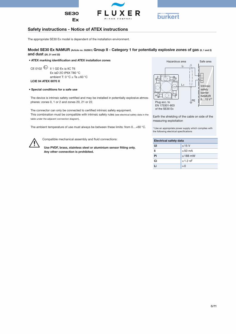
Model SE30 Ex NAMUR (Article no. 552901) Group II ‑ Category 1 for potentially explosive zones of gas (0, 1 and 2)
and dust (20, 21 and 22)
• ATEX marking identification and ATEX installation zones
CE 0102 II 1 GD Ex ia IIC T6 Ex iaD 2O IP6X T80 °C ambient T: 0 °C ≤ Ta ≤ 60 °C
LCIE 04 ATEX 6070 X
• Special conditions for a safe use
The device is intrinsic safety certified and may be installed in potentially explosive atmos-pheres: zones 0, 1 or 2 and zones 20, 21 or 22.
The connector can only be connected to certified intrinsic safety equipment. This combination must be compatible with intrinsic safety rules (see electrical safety data in the
table under the adjacent connection diagram).
The ambient temperature of use must always be between these limits: from 0…+60 °C.
1
3 2+
-
L+
L-
PE
Hazardous area Safe area
IntrinsicsafetybarrierNAMUR8…15 V¹⁾
Plug acc. toEN 175301-803of the SE30 Ex
Earth the shielding of the cable on side of the measuring exploitation
1) Use an appropriate power supply which complies with the following electrical specifications
Compatible mechanical assembly and fluid connections:
Use PVDF, brass, stainless steel or aluminium sensor fitting only. Any other connection is prohibited.
Electrical safety data
Ui ≤ 15 V
li ≤ 50 mA
Pi ≤ 188 mW
Ci ≤ 1.2 nF
Li ≈ 0
SE30Ex
7/11
Safety instructions - Notice of ATEX instructions
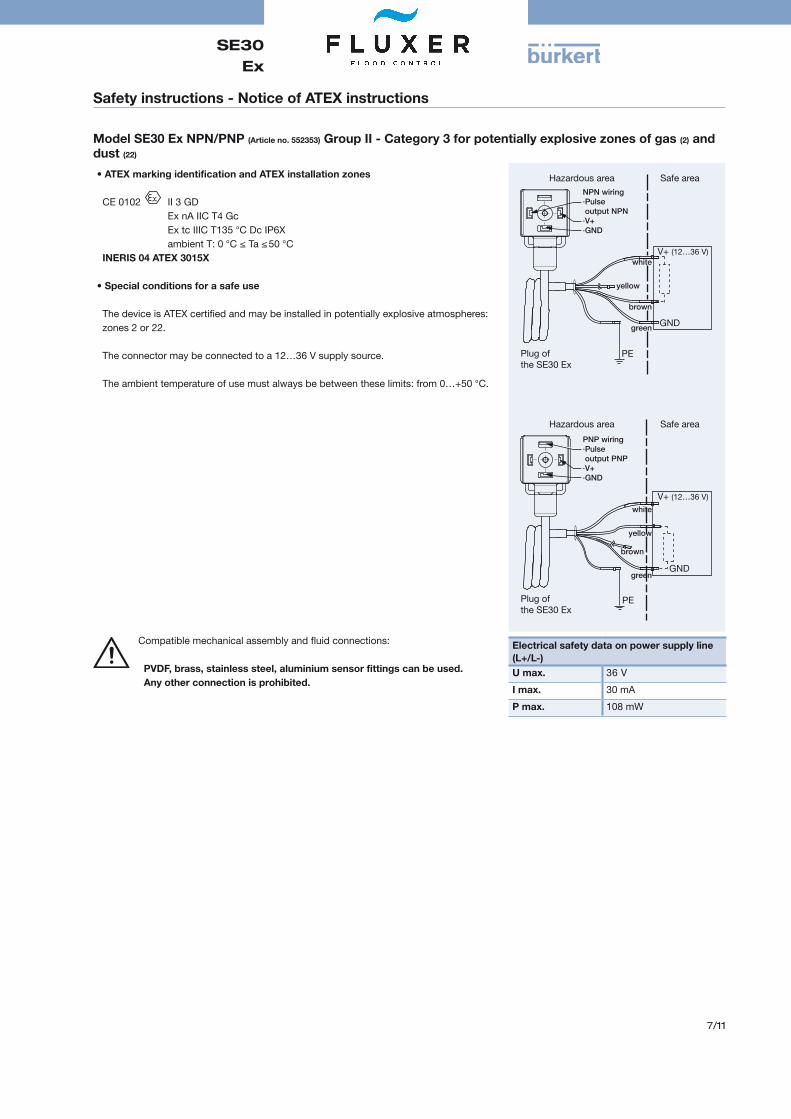
Model SE30 Ex NPN/PNP (Article no. 552353) Group II - Category 3 for potentially explosive zones of gas (2) and dust (22)
• ATEX marking identification and ATEX installation zones
CE 0102 II 3 GD Ex nA IIC T4 Gc Ex tc IIIC T135 °C Dc IP6X ambient T: 0 °C ≤ Ta ≤ 50 °C
INERIS 04 ATEX 3015X
• Special conditions for a safe use
The device is ATEX certified and may be installed in potentially explosive atmospheres: zones 2 or 22.
The connector may be connected to a 12…36 V supply source.
The ambient temperature of use must always be between these limits: from 0…+50 °C.
GND
PE
PE
GND
Hazardous area Safe area
Plug of the SE30 Ex
V+ (12…36 V)
V+ (12…36 V)
Hazardous area Safe area
Plug of the SE30 Ex
NPN wiring·Pulse output NPN·V+·GND
white
yellow
brown
green
PNP wiring·Pulse output PNP·V+·GND
white
yellow
brown
green
Compatible mechanical assembly and fluid connections:
PVDF, brass, stainless steel, aluminium sensor fittings can be used. Any other connection is prohibited.
Electrical safety data on power supply line (L+/L‑)U max. 36 V
I max. 30 mA
P max. 108 mW

SE30Ex
8/11
Dimensions [mm]
Electronics SE30 Ex ‑ Version NAMUR with cable plug (supplied)
40
66
9
54
44
32
Mounted on S030 sensor fitting DN H 06 9608 9615 10120 9825 9832 10240 10650 11265 112
HMounted on S077 sensor fitting
DN H15 8725 9640 10850 11880 168100 184
Threaded connection
Flanged connection
DN15 DN25 DN40 DN50 DN80
DN15 DN25 DN40 DN50 DN80
H
Electronics SE30 Ex ‑ Version NPN/PNP with cable plug* with 5 or 12 m cable (not supplied))
4066
9
54
54
44
Mounted on S030 sensor fitting DN H 06 9608 9615 10120 9825 9832 10240 10650 11265 112
H
Mounted on S077 sensor fitting DN H15 8725 9640 10850 11880 168100 184
Threaded connection
Flanged connection
DN15 DN25 DN40 DN50 DN80
DN15 DN25 DN40 DN50 DN80
H
* NOTE: Cable plug Type 2513 has to be ordered separately. The cable output is always oriented perpendicularly to the pipe.
SE30Ex
9/11
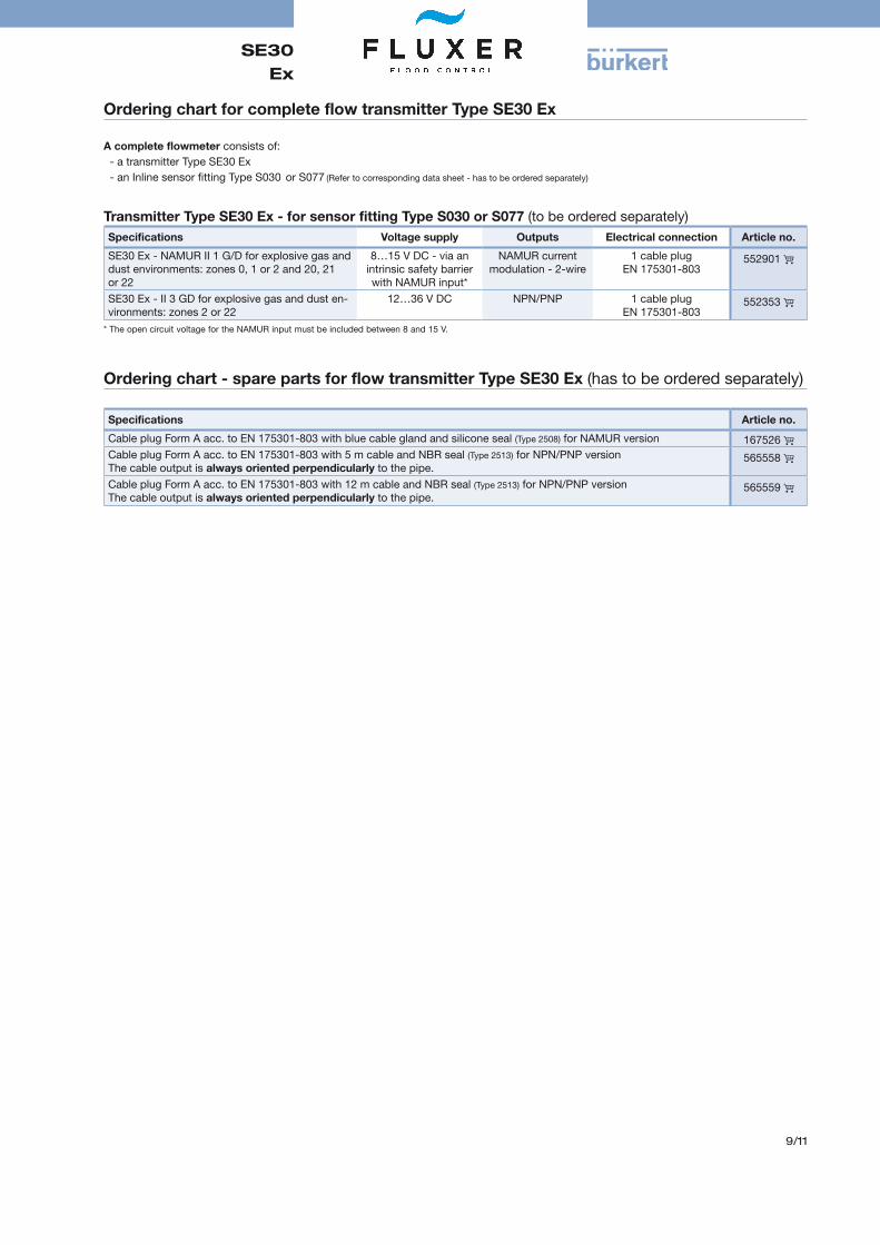
Ordering chart for complete flow transmitter Type SE30 Ex
A complete flowmeter consists of: - a transmitter Type SE30 Ex- an Inline sensor fitting Type S030 or S077 (Refer to corresponding data sheet - has to be ordered separately)
Transmitter Type SE30 Ex ‑ for sensor fitting Type S030 or S077 (to be ordered separately)Specifications Voltage supply Outputs Electrical connection Article no.
SE30 Ex - NAMUR II 1 G/D for explosive gas and dust environments: zones 0, 1 or 2 and 20, 21 or 22
8…15 V DC - via an intrinsic safety barrier with NAMUR input*
NAMUR current modulation - 2-wire
1 cable plug EN 175301-803
552901
SE30 Ex - II 3 GD for explosive gas and dust en-vironments: zones 2 or 22
12…36 V DC NPN/PNP 1 cable plug EN 175301-803
552353
* The open circuit voltage for the NAMUR input must be included between 8 and 15 V.
Ordering chart ‑ spare parts for flow transmitter Type SE30 Ex (has to be ordered separately)
Specifications Article no.
Cable plug Form A acc. to EN 175301-803 with blue cable gland and silicone seal (Type 2508) for NAMUR version 167526 Cable plug Form A acc. to EN 175301-803 with 5 m cable and NBR seal (Type 2513) for NPN/PNP version The cable output is always oriented perpendicularly to the pipe.
565558
Cable plug Form A acc. to EN 175301-803 with 12 m cable and NBR seal (Type 2513) for NPN/PNP version The cable output is always oriented perpendicularly to the pipe.
565559

SE30Ex
10/11
Safety barrier
• 2 or 4 channels, intrinsic safety digital inputs: proximitydetectors NAMUR, contacts…
• Rail mount on hat profile 35 mm
• All connections by removable screw terminals
Specifications
Digital inputs Each of the 4 x intrinsic safety inputs can be configured independently for a contact or a proximity detector NAMUR as per DIN 19234
Intrinsic safety inputs Proximity detector NAMUR as per DIN 19234 or free potential contacts, relays, pressure or temperature switches or push buttons in hazard-ous area.
Non intrinsic safetyrecopy outputs
Collector cut-off power
According to the type of sensor and the chosen logic: a green LED on the front panel displays a free-potential contact for each channel without common wire. 15 V - 60 mA - 0.9 VA - 350 Hz
Selection of the sensor type
Inductive / capacitive intrinsic safety certified NAMUR proximity detector or free-potential contacts.
Selection of the logic By a mini-DIP choice of active proxim-ity switches or when contact is NO (Normally Open) or NC (Normally Closed).
Fault detector For all inputs configured as NAMUR, all models are provided with fault de-tector (broken line or short-circuit). In faulty case, the green front LED switches off, the contact of the defective channel opens and the red LED cor-responding to the defective channel switches on. Other channels are not affected.
Power supply 24 V DC ±10 % 230 V AC ±10 % 1 front panel yellow LED is “ON” when supply is active
Consumption 5 VA
Specifications (continued)
Connections All connections by removable screw terminals. Supply distribution by means of a flat cable from one unit to the next one.
Classification for explo-sive areas
Intrinsic safety associated apparatus. It must be installed in safe area and connected to materials installed
in zone 0, 1 or 2 - Gas (G) or in zone 20, 21 or 22 - Dust (D)
Classification according to 2014/34/EU ATEX directives:
I/II (M1)/(1) G/D [EEx ia] IIC Safety parameters see EC-type certifi-cate LCIE 00ATEX 6034X
Ambient TemperatureOperating
Storage
-20…+60 °C-20…+50 °C (recommended)-40…+80 °C
Dimensional and me-chanical
Housing for symmetrical DIN rail (hat profile 35 mm as per standard NFC63015 / EN50022)Depth:120 mm ; Height: 90…145 mm overall including space for cables; Width on rail: 29.5 mm.; minimal dis-tance between rails: 180 mm.
Installations conditionsMounting on DIN rail:
Mounting inside a cabi-net:
must take into account thermal dis-sipation and risk of overheating gen-erated by housings installed side by side. In case of a high concentration inherent safety barrier, we recommend to leave a free space of 10 mm be-tween each group of 8 units (horizontal rail) and between each group of 4 units (vertical rail). It is recommended to close the electri-cal cabinet and to ensure a circulation of fresh air even by means of an air conditioner to keep the inside temper-ature at the level compatible with the recommended operating temperature among the units.
Ordering chart intrinsic safety barrier
Classifications for explosive areas Voltage supply Outputs Number of channels Article no.
2014/34/EU ATEX directives I/II (M1)/(1) G/D [EEx ia] IIC
24 V DC open collector, 15 V, 60 mA 2, with NAMUR input 553456 open collector, 15 V, 60 mA 4, with NAMUR input 553457
230 V AC open collector, 15 V, 60 mA 2, with NAMUR input 553458 open collector, 15 V, 60 mA 4, with NAMUR input 553459

SE30Ex
11/11
Interconnection possibilities of the complete flowmeter Type SE30 Ex with other Bürkert products
Type 8619multiCELL Transmitter/Controller
Type SE30 Ex Electronics + S030
Potentially Explosive ZoneIntrinsic safety barrier with NAMUR input
Type 8025 ‑ Batch transmitter wall-mounted or panel-mounted version
Type 8025 ‑Universal transmitter wall-mounted or pan-el-mounted version
Type 8032 ‑ Flow transmitter wall-mounted version
SE30 Ex with marking II 1 G/D (NAMUR version)
PLC
Type SE30 Ex Electronics + S077
SE30 Ex with marking II 3 GD (NPN/PNP version)
Potentially Explosive Zone Type 8025 ‑ Batch transmitter wall-mounted or panel-mounted version Type 8032 ‑
Flow transmitter wall-mounted version
Type 8025 ‑Universal transmit-ter wall-mounted or panel-mounted version
PLC
Type 8619multiCELL Transmitter/Controller
Type SE30 Ex Electronics + S077
Type SE30 Ex Electronics + S030