twinstar arf helicopter - centuryhelimedia.com · remote fueling valve (cnt4444) ... using a...
TRANSCRIPT
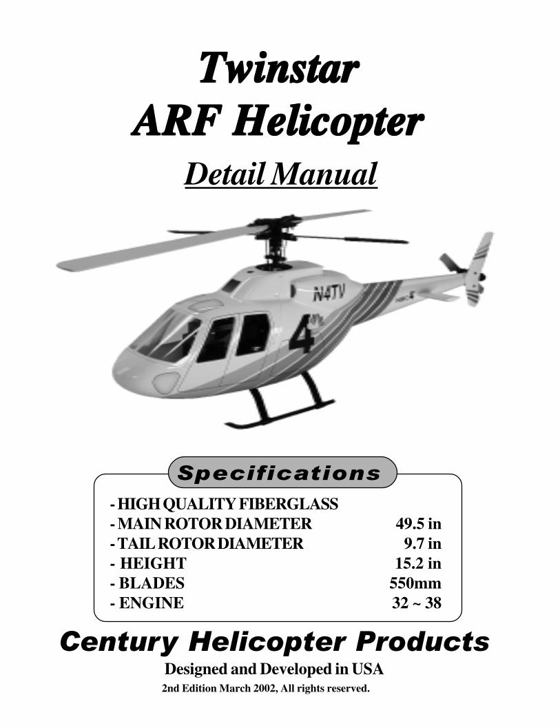
TwinstarTwinstarTwinstarTwinstarTwinstarARF HelicopterARF HelicopterARF HelicopterARF HelicopterARF Helicopter
Detail Manual
- HIGH QUALITY FIBERGLASS- MAIN ROTOR DIAMETER 49.5 in- TAIL ROTOR DIAMETER 9.7 in- HEIGHT 15.2 in- BLADES 550mm- ENGINE 32 ~ 38
Century Helicopter ProductsDesigned and Developed in USA2nd Edition March 2002, All rights reserved.
Specifications
2
Congratulations on your purchase of Century Helicopters Product’s Twinstar scale helicopter kit. TheARF helicopter is the beginning of a new breed of AAAAAlmost RRRRReady to FFFFFly pre-painted scale helicopters thatare simpler to build, easier to see and look fantastic. For those that have the complete kit version,you have great flexibility to make choices when installing the mechanics and apply an awesomepaint design of your own. Whether you are just beginning in helicopters, wanting to start in scaleor an accomplished pilot, Century offers a helicopter to fulfill your dreams in scale. Century hascombined their world class helicopter mechanics with awesome ARF fiberglass fuselages designedto mount directly inside without modifications.
Building Instructions for:
CN1075 Twinstar Scale Helicopter KitCN1075A Twinstar Painted Scale Helicopter w/ ARF Mechanics
IntroductionIntroductionIntroductionIntroductionIntroduction
WarningWarningWarningWarningWarning
The Twinstar scale helicopter kit must be assembled and installed in accordance with these instructions.Failure to do so could cause failures in the fuselage or the helicopter mechanics. Such failures could resultin serious injuries. It is strongly recommended that if you are in doubt of your abilities, you should seekthe assistance from experienced radio control modelers and associations. As manufacturer, we assume noliability for the use of this product.
Pre-assembly InformationPre-assembly InformationPre-assembly InformationPre-assembly InformationPre-assembly Information
Upon opening the Twinstar scale helicopter, you will find the major fiberglass and clear component partsand hardware bags. Hardware is identified by the size of the fastener or part. This is done for ease ofassembly. Be careful when opening bags as not to lose any hardware, whenever possible, keep all screwsin a container until you use them up through the assembly process. Care has been taken in the filling andpackaging of each bag. However, mistakes do happen. If there is a shortage or missing hardware, pleasecontact us at:
Century Helicopter Products523 Sinclair Frontage Road
Milpitas, CA 95035Fax:408-942-9524
www.centuryheli.com

3
Detail Instructions:Detail Instructions:Detail Instructions:Detail Instructions:Detail Instructions:This manual has been written to cover the assembly of the Twinstar scale helicopter kit and the ARF Paintedversion. This is the detail construction of the Twinstar fuselage components that work in cooperation with thescale mechanics instruction manual. For modelers building the kit version, all mechanics fitting (landing gear,muffler exhaust, tail gearbox, fuel system components and radio mounting) must be completed before the fuselageis painted as this will reveal any addition access holes that need to be cut-out. This is much simpler before paintingis complete.
Building Level:Building Level:Building Level:Building Level:Building Level:Level 1. Beginners will follow all steps and sections in order as they are laid out, this is a longer process that
involves building the mechanics completely, running-in the engine and then disassembling the helicopter toinstall into the completed fuselage.
Level 2. Intermediate to expert modelers can complete the fuselage and build & install the helicopter simulta-neously using a previously run-in engine.
Instructional InformationInstructional InformationInstructional InformationInstructional InformationInstructional InformationEvery attempt has been made to ease the assembly of your helicopter, at each step where there are complexassemblies, there are detailed drawings, photos and written instructions to walk you through each step. Rememberto take a few minutes before each step to carefully examine the instructions in order to become familiar with theparts and assembly sequence before beginning that step.
Twinstar Detail Construction Manual
Symbols used to help assist you in building:
Apply“Goop”
SpecialAttention
Repeat Stepas Specified
ApplyThreadlock
PartiallyTighten
PurchasedSeparately
HelpfulTip
Cut awayShaded Portion
Hardware Description and Identification: M3x6 = 3 x 6mm and can refer to screws or fasteners:
Required Items to complete the Twinstar Fuselage kit: Recommended Tools & Accessories:
Pencil & Ruler Clear Fuel Proof PaintSlow CA Glue 1/4” Paintbrush1/16”, 1/8” Drill Bit ScissorsRegular Hand Tools Paint, primer and filler*Masking Tape 320 Grit SandpaperLead Weight 30 Minute EpoxyFoam Rubber Sanding Blocks*Permanent Marker Locktite (liquid thread lock)Rubbing Alcohol Disposable epoxy brushes
Moto Tool w/ sanding accessoriesRemote Glow Plug Connector (CN2222)Remote Fueling Valve (CNT4444)5.0mm Open End Wrench5.5mm Open End Wrench7.0mm Open End Wrench
* For unassembled fuselage kit version.
M3x6 Self Tapping ScrewM - metric3 - diameter6 - length
M3x10 Socket Cap ScrewM - metric3 - diameter6 - length
4
The mechanics (completely built helicopter without body) should be flight ready. At this point the helicoptershould essentially be together without the fuselage, this can be accomplished with the scale mechanics instructionmanual that comes with the kit and ARF versions. For the kit version, complete all the fitting before painting.
The final items that need to be finished are:1. The battery pack and the receiver (wrapped in foam) are installed in front or below the battery tray. If mounting
infront for balance, suitable anchoring need to be fabricated to securely hold the items.2. The antenna needs to be routed to the tail gearbox with out contacting any metal or wiring. Optional short whip
antennas are great but either method needs to be routed correctly.3. Remote glow plug adapter and fueling system needs to be installed (purchased separately).4. The engine Run-in will require 2-4 tanks of fuel to get the engine running smoothly (with main blades).5. Rudder pushrod length needs to be shortened and adjusted based on the rudder setup instructions.6. During the Run-in, cycle the throttle to lift-off and trim the rudder while setting up the gyro.
Do not fly the helicopter at this stage, the mechanics are designed for the scale fuselage and is not balanced forextended hovering or forward flight. Also note that the is no tail support strut or tail fins (apart of the fuselage)for stability.
Section Two: Fuselage PreparationSection Two: Fuselage PreparationSection Two: Fuselage PreparationSection Two: Fuselage PreparationSection Two: Fuselage Preparation
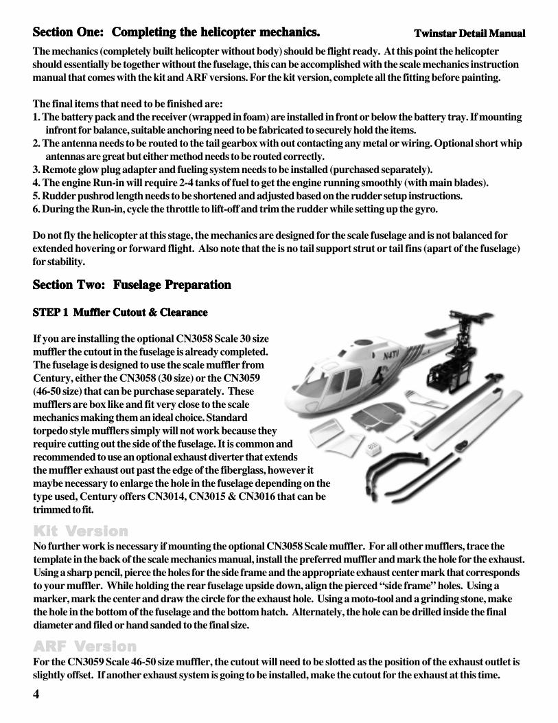
STEP 1 Muffler Cutout & ClearanceSTEP 1 Muffler Cutout & ClearanceSTEP 1 Muffler Cutout & ClearanceSTEP 1 Muffler Cutout & ClearanceSTEP 1 Muffler Cutout & Clearance
If you are installing the optional CN3058 Scale 30 sizemuffler the cutout in the fuselage is already completed.The fuselage is designed to use the scale muffler fromCentury, either the CN3058 (30 size) or the CN3059(46-50 size) that can be purchase separately. Thesemufflers are box like and fit very close to the scalemechanics making them an ideal choice. Standardtorpedo style mufflers simply will not work because theyrequire cutting out the side of the fuselage. It is common andrecommended to use an optional exhaust diverter that extendsthe muffler exhaust out past the edge of the fiberglass, however itmaybe necessary to enlarge the hole in the fuselage depending on thetype used, Century offers CN3014, CN3015 & CN3016 that can betrimmed to fit.
Section One: Completing the helicopter mechanics.Section One: Completing the helicopter mechanics.Section One: Completing the helicopter mechanics.Section One: Completing the helicopter mechanics.Section One: Completing the helicopter mechanics.
ARFARFARFARFARF VVVVVererererersionsionsionsionsionFor the CN3059 Scale 46-50 size muffler, the cutout will need to be slotted as the position of the exhaust outlet isslightly offset. If another exhaust system is going to be installed, make the cutout for the exhaust at this time.
KitKitKitKitKit VVVVVererererersionsionsionsionsionNo further work is necessary if mounting the optional CN3058 Scale muffler. For all other mufflers, trace thetemplate in the back of the scale mechanics manual, install the preferred muffler and mark the hole for the exhaust.Using a sharp pencil, pierce the holes for the side frame and the appropriate exhaust center mark that correspondsto your muffler. While holding the rear fuselage upside down, align the pierced “side frame” holes. Using amarker, mark the center and draw the circle for the exhaust hole. Using a moto-tool and a grinding stone, makethe hole in the bottom of the fuselage and the bottom hatch. Alternately, the hole can be drilled inside the finaldiameter and filed or hand sanded to the final size.
Twinstar Detail Manual Twinstar Detail Manual Twinstar Detail Manual Twinstar Detail Manual Twinstar Detail Manual
5
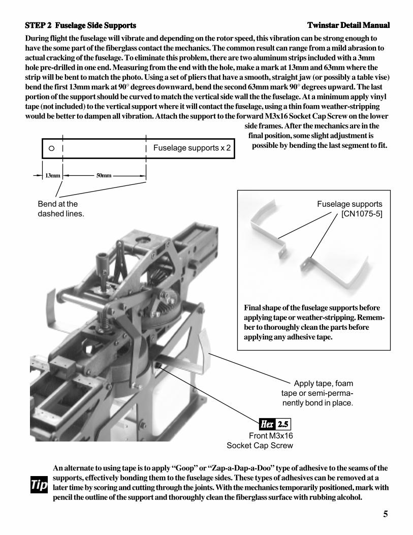
During flight the fuselage will vibrate and depending on the rotor speed, this vibration can be strong enough tohave the some part of the fiberglass contact the mechanics. The common result can range from a mild abrasion toactual cracking of the fuselage. To eliminate this problem, there are two aluminum strips included with a 3mmhole pre-drilled in one end. Measuring from the end with the hole, make a mark at 13mm and 63mm where thestrip will be bent to match the photo. Using a set of pliers that have a smooth, straight jaw (or possibly a table vise)bend the first 13mm mark at 90° degrees downward, bend the second 63mm mark 90° degrees upward. The lastportion of the support should be curved to match the vertical side wall the the fuselage. At a minimum apply vinyltape (not included) to the vertical support where it will contact the fuselage, using a thin foam weather-strippingwould be better to dampen all vibration. Attach the support to the forward M3x16 Socket Cap Screw on the lower
side frames. After the mechanics are in thefinal position, some slight adjustment ispossible by bending the last segment to fit.
STEP 2 Fuselage Side SupportsSTEP 2 Fuselage Side SupportsSTEP 2 Fuselage Side SupportsSTEP 2 Fuselage Side SupportsSTEP 2 Fuselage Side Supports
Final shape of the fuselage supports beforeapplying tape or weather-stripping. Remem-ber to thoroughly clean the parts beforeapplying any adhesive tape.
Fuselage supports[CN1075-5]
An alternate to using tape is to apply “Goop” or “Zap-a-Dap-a-Doo” type of adhesive to the seams of thesupports, effectively bonding them to the fuselage sides. These types of adhesives can be removed at alater time by scoring and cutting through the joints. With the mechanics temporarily positioned, mark withpencil the outline of the support and thoroughly clean the fiberglass surface with rubbing alcohol.
Apply tape, foamtape or semi-perma-nently bond in place.
Front M3x16Socket Cap Screw
2.52.52.52.52.5HexHexHexHexHex
13mm 50mm
Bend at thedashed lines.
Fuselage supports x 2
Twinstar Detail Manual Twinstar Detail Manual Twinstar Detail Manual Twinstar Detail Manual Twinstar Detail Manual

6
Insert the main mechanics (with the main shaft removed) with the completed rudder pushrod guides permanentlyinstalled, insert the mechanics past the pre-drilled landing gear holes until the end of the tail boomextends past the fiberglass by 1/2” [12mm], be carefull not to pull out the tail drive shaft with thebearings as the forward joint can be disengaged, requiring disassembly to re-attach. As-semble the tail gear box with the tail blade assembly onto the right side (as viewedfrom behind) over the tail boom, aligning the tail input gear into the matingrecesses in the gearbox. Liberally apply grease to the tail gears and close thetail gearbox with left side, securing them together with two M3x12, oneM3x10 Socket Cap screws and three M3 Locknuts. Insert twoM3x20 Socket Cap screws from the right side of the gearbox andattach two 10mm threaded fin mounts using threadlock. The finmounts will need to be held with smooth jaw pliers to be suffi-ciently tightened.Cut a piece of 1/4” radio foam 1/2” wide by 2” long (same asused to isolate receiver and battery from vibration), whilemoving the mechanics to align to the landing gear holes, insertthe foam in-between the metal tail boom and the fiberglass tailsection, this will cushion the tail boom but make disassemblysimple.
Twinstar Detail Manual Twinstar Detail Manual Twinstar Detail Manual Twinstar Detail Manual Twinstar Detail Manual
Before the tail gear box can be assembled onto thetail boom, the tail boom must be secured tothe mechanics, the tail pushrod must beinstalled and the tail pushrod guidesmust be close to their final posi-tions, however there is no accessafter the mechanics are installed.Attach the tail boom with thedrive shaft assembly and ensurethe drive shaft is engaged in thetransmission drive shaft. Slide thethree tail pushrod guides onto thetail boom and roughly position them equally spaced along the tail boom. Insert the long rudder pushrod from theend of the tail boom but do not attach the plastic pushrod coupler. Complete the remainder of Step 4-9 in themechanics manual, including attaching the rudder ball link to the tail pitch lever but do not grease the gears in thegearbox. Slide the pushrod back and forth to get the best positioning for the tail guides. Once smooth operation isattained, tape each guide to the tail boom. Following the rudder setup instructions, shorten the threaded sectionclosest the plastic coupler, there is enough thread to remove 5-6mm from each end to position the tail bellcrank atthe correct angle. Now remove the tail gearbox and take the entire main mechanics (removing the main shaft & muffler makesthis easier) with tailboom and insert into the rear fuselage and observe where the pushrod exists the end of thefiberglass tail boom. Make a pencil mark where the tail pushrod exits the fiberglass, this should be directly under-neath the tail boom. The rearmost guide may need to be moved forward to properly fit inside the fiberglass tailboom and a 3/32” [2.5mm] slot cut into the bottom of the tail boom to get proper clearance and free movement. Ifneeded, cut the slot with a moto-tool or razor saw and file the edges smooth. A “trim and test” procedure maybenecessary to repeat until the slot is long enough. Once completed, glue the pushrod guides onto the tail boom withslow-CA (only a few drops around the outside are needed to sufficiently attach the guides.
STEP 3 Attaching the Tail Boom & Tail PushrodSTEP 3 Attaching the Tail Boom & Tail PushrodSTEP 3 Attaching the Tail Boom & Tail PushrodSTEP 3 Attaching the Tail Boom & Tail PushrodSTEP 3 Attaching the Tail Boom & Tail Pushrod
In addition toStep 4-9 in
Scale Manual
STEP 4 Tail Gearbox Assembly & Vertical Fin MountsSTEP 4 Tail Gearbox Assembly & Vertical Fin MountsSTEP 4 Tail Gearbox Assembly & Vertical Fin MountsSTEP 4 Tail Gearbox Assembly & Vertical Fin MountsSTEP 4 Tail Gearbox Assembly & Vertical Fin Mounts
M3x20 SHCS x 2Threaded Fin
Mounts x 2[CN1075-5]

7
STEP 5 Vertical Tail FinSTEP 5 Vertical Tail FinSTEP 5 Vertical Tail FinSTEP 5 Vertical Tail FinSTEP 5 Vertical Tail Fin
The vertical tail fin is attached with the short portion on the bottom. Slideone M3 Washer onto one M3x12 Socket Cap screw and insert throughthe pre-drilled hole in the vertical fin, repeat for the second hole. Applythread lock to the exposed threads and thread into the vertical fin mountsalready installed on the tail gearbox. Be careful, tighten until snug andthen only a 1/16” of a turn more. Warning, these fasteners only hold thefin in place, overtightening will crush the fin.
KitKitKitKitKit VVVVVererererersionsionsionsionsionThe edges of the fin need to be sanded before the paint in applied.After painting, the holes for the screws will need to be re-drilled toremove any paint that accumulated in the holes.
M3x12 SHCS x 2M3 Flat Washer x 2
[CN1075-5]
STEP 6 Landing Gear & Muffler AttachmentSTEP 6 Landing Gear & Muffler AttachmentSTEP 6 Landing Gear & Muffler AttachmentSTEP 6 Landing Gear & Muffler AttachmentSTEP 6 Landing Gear & Muffler Attachment
Vertical Fin(unfinished)[CN1075-3]
As there is enough space to attach the 30 size muffler after the mechanics are secured tothe landing gear, remove it for now. If you have chosen to install the 46-50 size engine, itis very important that the muffler screws are installed loosely in the engine before the sideframes are attached, if this is not the case, do it now. Place the mechanics and the rear fuselage on top of theassembled landing gear. Slide one M3 Flat Washer onto one M3x15 Socket Cap screw and insert from the bottomof the front landing strut, through the fiberglass floor and the align to the front hole of the mechanics. Attach oneM3 Locknut on the inside using pliers to hold the nut while the bolt is tightened from below. Repeat for the otherside. To attach the rear strut, repeat the same procedure but tip the mechanics over the side of a table. Using a5.5mm nut driver, place a drop of grease on the top of the locknut and insert into the nut driver (this will hold thenut from falling out) and carefully insert the nut driver between the side of the mechanics and the fuselage. Youwill need to maneuver past the angle supports but with patients and keeping the nut driver horizontal, the rearlocknuts can be secured. This can also be accomplished with the muffler installed but more patience is needed asyou are unable to see the bolt. Repeat for the other side,this time with the fuel tank as the challenge.
It is assumed that the muffler holes have beencut for the muffler to be installed, the edge ofthe hole should be fuel proofed with a Polyure-thane paint or simple clear nail polish to sealthe paint finish to the fiberglass. There isenough room to use a long allen key or hexscrewdriver to access the muffler bolts. Ifyou have been test flying the mechanics,clean the muffler bolts, the muffler threadsand the through holes on the engine withrubbing alcohol before assembling. Makean aluminum gasket if none is providedwith the muffler, after tightening the bolts,torque an additional 1/16” of a turn.Finally, run the pressure line back to thefuel tank and arrange any other fuel linesfor optional filler valves or fittings.
M3Locknuton top.
M3x15 SHCS x 4M3 Flat Washer x 4M3 Locknut x 4
Rear Body withBottom Hatch
(unfinished)[CN1075-2]
Twinstar Detail Manual Twinstar Detail Manual Twinstar Detail Manual Twinstar Detail Manual Twinstar Detail Manual
8
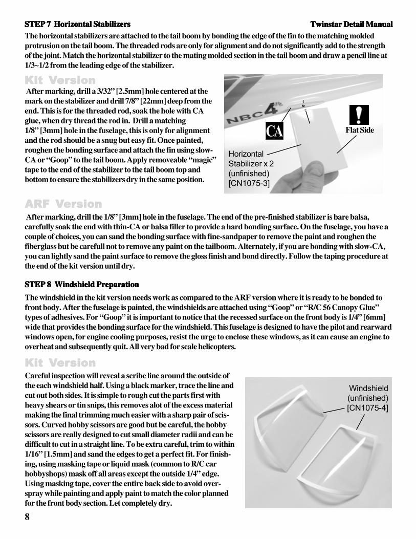
The windshield in the kit version needs work as compared to the ARF version where it is ready to be bonded tofront body. After the fuselage is painted, the windshields are attached using “Goop” or “R/C 56 Canopy Glue”types of adhesives. For “Goop” it is important to notice that the recessed surface on the front body is 1/4” [6mm]wide that provides the bonding surface for the windshield. This fuselage is designed to have the pilot and rearwardwindows open, for engine cooling purposes, resist the urge to enclose these windows, as it can cause an engine tooverheat and subsequently quit. All very bad for scale helicopters.
STEP 7 Horizontal StabilizersSTEP 7 Horizontal StabilizersSTEP 7 Horizontal StabilizersSTEP 7 Horizontal StabilizersSTEP 7 Horizontal Stabilizers
After marking, drill a 3/32” [2.5mm] hole centered at themark on the stabilizer and drill 7/8” [22mm] deep from theend. This is for the threaded rod, soak the hole with CAglue, when dry thread the rod in. Drill a matching1/8” [3mm] hole in the fuselage, this is only for alignmentand the rod should be a snug but easy fit. Once painted,roughen the bonding surface and attach the fin using slow-CA or “Goop” to the tail boom. Apply removeable “magic”tape to the end of the stabilizer to the tail boom top andbottom to ensure the stabilizers dry in the same position.
After marking, drill the 1/8” [3mm] hole in the fuselage. The end of the pre-finished stabilizer is bare balsa,carefully soak the end with thin-CA or balsa filler to provide a hard bonding surface. On the fuselage, you have acouple of choices, you can sand the bonding surface with fine-sandpaper to remove the paint and roughen thefiberglass but be carefull not to remove any paint on the tailboom. Alternately, if you are bonding with slow-CA,you can lightly sand the paint surface to remove the gloss finish and bond directly. Follow the taping procedure atthe end of the kit version until dry.
The horizontal stabilizers are attached to the tail boom by bonding the edge of the fin to the matching moldedprotrusion on the tail boom. The threaded rods are only for alignment and do not significantly add to the strengthof the joint. Match the horizontal stabilizer to the mating molded section in the tail boom and draw a pencil line at1/3~1/2 from the leading edge of the stabilizer.
ARFARFARFARFARF VVVVVererererersionsionsionsionsion
KitKitKitKitKit VVVVVererererersionsionsionsionsion
HorizontalStabilizer x 2(unfinished)[CN1075-3]
STEP 8 Windshield PreparationSTEP 8 Windshield PreparationSTEP 8 Windshield PreparationSTEP 8 Windshield PreparationSTEP 8 Windshield Preparation
Careful inspection will reveal a scribe line around the outside ofthe each windshield half. Using a black marker, trace the line andcut out both sides. It is simple to rough cut the parts first withheavy shears or tin snips, this removes alot of the excess materialmaking the final trimming much easier with a sharp pair of scis-sors. Curved hobby scissors are good but be careful, the hobbyscissors are really designed to cut small diameter radii and can bedifficult to cut in a straight line. To be extra careful, trim to within1/16” [1.5mm] and sand the edges to get a perfect fit. For finish-ing, using masking tape or liquid mask (common to R/C carhobbyshops) mask off all areas except the outside 1/4” edge.Using masking tape, cover the entire back side to avoid over-spray while painting and apply paint to match the color plannedfor the front body section. Let completely dry.
KitKitKitKitKit VVVVVererererersionsionsionsionsion
Windshield(unfinished)[CN1075-4]
Flat Side
Twinstar Detail ManualTwinstar Detail ManualTwinstar Detail ManualTwinstar Detail ManualTwinstar Detail Manual
CA

9
STEP 9 Attach the Main Rotor HeadSTEP 9 Attach the Main Rotor HeadSTEP 9 Attach the Main Rotor HeadSTEP 9 Attach the Main Rotor HeadSTEP 9 Attach the Main Rotor Head
Now the rotor head assembly must be re-attached, insert the mainshaft through the top bearing, the mast stopper and insert theM3x16 Socket Cap screw below the main gear at a 45° angle.Once through the auto-hub use a 2.5hex key to turn the boltwhile holding the M3 Locknut with pliers from the other sideat 45° degree angle. Access to the set screws in the maststopper is possible through the elevator lever assembly(disconnect the lever to do this) but remember to pull upon the main shaft first, tighten one set screw then removethe second to apply threadlock. Finally, remove the first,apply threadlock and tighten in place. If using theslipper unit, access is possible between the startershaft and the side frames from the front.
STEP 10 Front NoseSTEP 10 Front NoseSTEP 10 Front NoseSTEP 10 Front NoseSTEP 10 Front Nose
The front nose is attached with four M3x8 Phillips Self Tapping screws from each side. Bonded to the inside aresmall 3/8” plywood squares that the hold the screws in place. Take the time now to mount the gyro, receiver andbattery pack (wrapped in foam) inside the front nose if it wasn’t already done for testflying. The location for the gyro is on the battery tray beside the collectiveand throttle servos. Having completed the mechanics, lift thehelicopter by the flybar held perpendicular to thelength of the helicopter and continue tomove the battery pack forward untilbalance is achieved. It maybe necessaryto construct an anchor, like a fewsimple metal hooks bonded to theinside of the nose to hold rubberbands securing the battery pack. Ifmore weight is necessary, addingweight is acceptable but becautious to the amount, if lead isbeing used, bond it as far forwardas possible. See Step 14.
KitKitKitKitKit VVVVVererererersionsionsionsionsionFront Body(unfinished)[CN1075-1]
M3x8 Self TappingScrews x 8
[CN1075-5]
Mark the four screw locationson the each side of the frontnose with a pencil. Using tape,attach the front to the rear body and slowly drill each of the eight holes using a 3/32” [2.5mm] drill bit. Removethe front nose and roughen one side of the eight plywood blocks and the area around the inside hole on the rearbody. Remember that the fiberglass parts are molded using Polyester resin and as a result, “Epoxy” type of gluewill not bond to the fiberglass. Any time two components are bonded to the fiberglass, slow to medium speed CA(cyanoacrylate) adhesive is necessary. Using slow-CA bond each plywood block in place, clamp until dry. Redrilleach hole in the rear body through the plywood blocks and using one M3x8 Phillips Self Tapping screw, insertand form the threads. After the fuselage is painted the front nose can be attached, remember to paint the screws tomatch the color scheme.
Twinstar Detail ManualTwinstar Detail ManualTwinstar Detail ManualTwinstar Detail ManualTwinstar Detail Manual

10
STEP 11 Bottom HatchSTEP 11 Bottom HatchSTEP 11 Bottom HatchSTEP 11 Bottom HatchSTEP 11 Bottom Hatch
STEP 12 Attaching the WindshieldsSTEP 12 Attaching the WindshieldsSTEP 12 Attaching the WindshieldsSTEP 12 Attaching the WindshieldsSTEP 12 Attaching the Windshields
If an exhaust diverter is to be used, installbefore the bottom hatch is attached. Thebottom hatch is already cut to fit the landinggear on the scale mechanics. Start by insert-ing the rear cutouts and gently flexing theears to engage the rear struts, next grasp thehatch with both hands, fingers on the sideedges and thumbs centered at the front andgently bend the hatch in a “U” shape to allowthe front lip of the hatch to be inserted underthe edge of the front nose. Secure the hatchusing six M3x8 Phillips Self Tapping Screws.
Rear Bodywith Bottom
Hatch(unfinished)[CN1075-2]M3x8 Self
TappingScrews x 6
[CN1075-5]
KitKitKitKitKit VVVVVererererersionsionsionsionsionMark the six screw locations on the hatch with apencil. Using tape, attach the hatch to the rear bodyand slowly drill each of the six holes using a3/32” [2.5mm] drill bit. Remove the hatch and roughen one side of the six plywood blocks and the area aroundthe inside hole on the rear body. Using slow-CA bond each plywood block in place, clamp until dry. Redrill eachhole in the rear body through the plywood blocks and using one M3x8 Phillips Self Tapping screw, insert andform the threads. After the fuselage is painted the hatch can be attached, remember to paint the screws to match thecolor scheme.
Twinstar Detail ManualTwinstar Detail ManualTwinstar Detail ManualTwinstar Detail ManualTwinstar Detail Manual
Apply a thin 1/16” [1.5mm] bead of adhesive centered in the recessedsurface. Pick up the windshield by the edges only, remember “Goop” or“Goop Fingerprints” cannot be removed if they touch a clear part.Using single-use “Hobby grease syringes” are great and reallymake this a simple task as the adhesive width and amountcan be easily controlled. Let dry for 24 hours. Anexcellent alternative is to use “R/C 56 CanopyGlue” from any airplane hobbyshop. This adhesiveremains white until fully curred in 24-48 hours(slow but very good) but can be cleaned up using acloth and will not damage or scuff clear parts. Whendry, it is very strong. After bonding, apply “magic”tape to secure the windshield halves until dry.
STEP 13 Fueling, Glow Plug Extension and Antenna RoutingSTEP 13 Fueling, Glow Plug Extension and Antenna RoutingSTEP 13 Fueling, Glow Plug Extension and Antenna RoutingSTEP 13 Fueling, Glow Plug Extension and Antenna RoutingSTEP 13 Fueling, Glow Plug Extension and Antenna Routing
If you have not already considered these items, now is the time. Most scale helicopter present new challenges tosimply change the glow plug when shrouded inside the fuselage. Century makes most items to solve these asfollows: CN2054 Universal Glow Wrench (check for compatibitity), CN2222 Remote Glow Plug Adapter -absolutely essential for all model helicopters and CNT4444 In-line fueling valve with filter and filler - avoidspulling the fuel line from the carburator to fuel the helicopter. The antenna wire needs to be routed in a path thatavoids the wire from touching any metal surfaces or servo wires. It is best that all the servo leads be collected andsecured on one side of the mechanics leaving the opposite side for the antenna. Whether you prefer the originalwire or use a “mini-whip” antenna, make sure that anytime the wire needs to cross any metal, use a short 1/2”[12mm] length of fuel tubing to insulate the wire and attach with a tie wrap. Clean installations always work best.

11
Congratulations, you have a fine looking scale Twinstar helicopter kit.The final work is in the balancing of the helicopterbefore flying. With the main blades and tailblades installed, pickup by the flybar with yourfingers and look to see how level the helicop-ter hangs in the fore-aft direction. If neces-sary, add nose weight to the to very frontof the fuselage. This can be glued insidethe front fuselage section infront of thebattery pack. Generally, 4-6 ounces isthe maximum weight that should beadded to the nose if you are using a30 size engine.
Do not be concerned that the flybarcomes close to the top of the fuselage.While working on the helicopter theangle of the flybar to the main shaft in notrealistic and when in flight, the flybar willnot deflect half the distance possible.
Happy flying with your gorgeous Twinstar fuselage.
STEP 14 Final BalancingSTEP 14 Final BalancingSTEP 14 Final BalancingSTEP 14 Final BalancingSTEP 14 Final Balancing Twinstar Detail ManualTwinstar Detail ManualTwinstar Detail ManualTwinstar Detail ManualTwinstar Detail Manual
STEP 15 DecalsSTEP 15 DecalsSTEP 15 DecalsSTEP 15 DecalsSTEP 15 Decals
For best results, apply the decals after the paint work is started and all the colors have been applied but before anyclear topcoat has been applied. Following this method will allow the decals to be sandwiched in the finish forgreatest appearance and longevity.
For the kit version, the next couple of pages describe the basic procedure to prepare and paint the fuselage.
Text, Logos &Grill Decals[CN1075-5]

12
This section is written to cover painting and detailing of fiberglass components using in Century’s scale helicopterkits. Some included references may describe components of different kits, not exclusive to this detail instructionmanual.
Introduction to FiberglassIntroduction to FiberglassIntroduction to FiberglassIntroduction to FiberglassIntroduction to FiberglassWhen considering the strength compared to the space age canopies that are common on most pod and boomhelicopters there is no contest. This plastic material is virtually indestructible at the penalty of being virtuallyun-paintable without specialized and expensive automotive primers and paints, there is also a very limited rangeof color available. The reason you are reading this page is that you have come to your senses and wanted to flya model that looks and holds all the prestige of a real helicopter.
FlexibilityFlexibilityFlexibilityFlexibilityFlexibilityA wonderful attribute of fiberglass is in its flexibility. Century and Funkey take care and pride in craftsmanshipthat goes into every fuselage. However, fiberglass parts will migrate (change shape) while inside the shippingbox. When two mating components are brought together and they do not align or mate, the culprit is a warpedpart. Many become upset and wish to lay blame but dealing with this is very simple when explained a simpleprocedure. Using a heat gun set at the high setting at a distance of 1-2 feet away, evenly heat the warped part untilthe outside surface is hot to the touch and the part has become pliable (flexible). Using adhesive tape, mate thetwo fiberglass parts together and let both parts sit until both parts have reached room temperature. Remove thetape and now both parts are stable and match one another. In some instances, depending on the location of thewarp, the part may need to be held in an overextended position to achieve the proper shape when the part isfinished.
Working with FiberglassWorking with FiberglassWorking with FiberglassWorking with FiberglassWorking with FiberglassDifficult to work with, we disagree. Fiberglass is easier to repair than you think. Using today’s CA type ofadhesives, a severe crack in a fuselage can be simply fixed and the repaired section is much stronger than in itsoriginal state. Add touchup paint and no one would ever know it had been damaged. There is a limit to this typeof thinking where purchasing the replacement fiberglass part is simply cheaper and less work than performingmajor reconstructive surgery.
The Paint Job.The Paint Job.The Paint Job.The Paint Job.The Paint Job.There is no magic to a good paint job, the true secret is time, patience and common sense. A beginner whothinks that they can throw paint onto a fuselage Friday night before flying on Sunday is dreaming, the helicopterwould be flyable but even that is a stretch. The average beginner will spend the better part of a month to applya good clean paint job.
Preparing the fuselage for painting.Preparing the fuselage for painting.Preparing the fuselage for painting.Preparing the fuselage for painting.Preparing the fuselage for painting.After opening the kit version of the fuselage, examine all the fiberglass components to see where work needs tobe done to allow a simple "bring up" of the fuselage. "Bring up" describes the necessary steps to complete allthe jobs in order to start priming the fiberglass parts. Typical work that is done at this stage is rough sanding onseams and jointed components, filling of surface imperfections, adding panel lines and rivets, cutting requiredholes and preparation for priming.
1. Start by thoroughly washing all fiberglass parts in mild detergent and warm water, this will remove anyresidue remaining from the molding process. Next wipe down all the parts with Acetone (from the hardwarestore). The Acetone will remove all traces of oil or grease that will affect the adhesion of two fiberglass parts orbetween the paint and the fiberglass. Now using fine steel wool or an abrasive pad commonly used for scrub-bing dishes, scuff all surfaces that will be joined or receiving paint. What is important to note here is that weare breaking through the topmost resin surface and creating the best surface for adhesive or primer to adhere to.
Section Three: Preparing and painting the kit version.Section Three: Preparing and painting the kit version.Section Three: Preparing and painting the kit version.Section Three: Preparing and painting the kit version.Section Three: Preparing and painting the kit version.

13
The prepared finish will have very fine score marks usually seen when the part is held to the light at a slight angle.
2. This is the time to rough sand any accessories or small parts, using the 320 grit sandpaper, that will be as-sembled and attached at different positions on the fuselage. These can be marking lights, engine exhausts, scalefuel tanks, horizontal and vertical stabilizers, guns, antenna or any scale details being bonded to the fuselage.These accessories should be test assembled to make sure that all parts are prepared, and you will be able to see anyproblems that may arise in trying to paint these parts. Some thought should be put into how to hold the part as it isbeing painted. Go ahead and bond these parts at this time using the slow CA glue. A quick note on adhesives, asthe fuselage resin is polyester, do not use any regular 5-30 minute epoxies to bonddo not use any regular 5-30 minute epoxies to bonddo not use any regular 5-30 minute epoxies to bonddo not use any regular 5-30 minute epoxies to bonddo not use any regular 5-30 minute epoxies to bond two fiberglass componentstogether. Stabilit is specially formulated for this purpose and excellent for fillets. Epoxy and polyester will notbond properly to one another, but epoxy is good to bond unlike substances like wood or metal to themselves orother parts.
3. Once the detail parts have been built into sub assemblies, they are ready to paint, use a filler in sections thathave gaps or slight surface imperfections, occasionally there are voids (air bubbles in the resin) that occur near thesurface that need to be filled. There are alot of good fiberglass fillers on the market, it is best to check with yourlocal hobby shop to get a recommended product. Try to stay away from porous fillers designed for wood as theywill shrink and are not a good choice for large areas.
4. Most major windows and accessory holes have been precut by Century, leaving only those that have a userdependency like the type of exhaust system used on the helicopter or the exact exit position for the cooling fanshroud. For these fuselages that have been explicitly designed for the Century’s scale mechanics, almost all ofthese concerns have been considered and finished at the factory. This leaves the hole for the exhaust, if you areusing the recommended scale muffler (CN3058 .32-.38 or CN3059 .46-.50) then these dimensions have beenincluded on a template in the Scale Mechanics Manual for the 30 size engine, the 46-50 requires a slight adjust-ment.
4a. When making cutouts or holes in the surface of the fiberglass the best procedure is to drill a pilot hole using a1/16" drill bit at corners or along a curve. Start with a permanent marker to draw the opening or window. Thepilot holes serve to avoid leaving sharp corners which given the nature of a model helicopter will be the focalpoint for stress cracking originating from corners. Once the holes have been made, use the moto-tool for all otherroughing cuts. The cut off wheel is the best for straight lines and either the sanding drum or the curved stone isused for smoothing edges. If the cut out is a window, do not use the moto-tool for the final work. Switch to asanding blocks, square blocks of various sizes for straight edges and round dowels for rounded corners.
4b. In the case of the exhaust opening, it should end up being 1/8" larger across the outside diameter of theexhaust pipe that extends below the bottom of the fuselage. After drawing the circle, use grinding stone and movein small circles until the hole is at the size wanted.
5. Priming the fuselage accomplishes two tasks: firstly, the primer paint is designed to aggressively adhere tothe surface being painted and provide the best surface for the colored paint to adhere to; secondly, all surfaceimperfections will become visible. Depending on the particular imperfection, light sanding with number 600 or800 sand paper and the second priming will take care of 90% of the highly visible problems. The remaining10% need to be filled, let dry, sanded again and then sprayed with the second coat of primer. The primer pro-cess will be repeated until the surface is as perfect as your patience and time permit.
6. Select your paint color and follow the directions on the particular brand of paint being used as each manufac-turer has different requirements.

Century Helicopter Products523 Sinclair Frontage Rd., Milpitas, CA 95035 USA
Fax:1-408-942-9524www.centuryheli.com email: [email protected]
Common Replacement Parts:CN1075-1 Front Body (unpainted) ........................................................................................... 1CN1075-2 Rear Body with Bottom Hatch (unpainted) ............................................................. 1CN1075-3 Tail Fin Set (unpainted) ........................................................................................... 1CN1075-4 Windshield (unfinished) ........................................................................................... 1CN1075-5 Hardware Set & Decal (logos & text only) .............................................................. 1CN1075-6 Detail & Scale Mechanics Manual........................................................................... 1CN2322 ARF Main Rotor Blades (550mm) Pair ................................................................... 1HI3122 Landing Struts (Twinstar) ........................................................................................ 2HW3123 Landing Skids (Twinstar) ........................................................................................ 2HW3062R Tail boom (Red anodized is for Twinstar & Long Ranger) ...................................... 1HW3064C Tail Pitch Control Rod Set need trim 10 or 20mm (for all) ...................................... 1
Optional Parts:CN0427 Hex one way start extension .................................................................................... 1CN2054 Universal Glow Plug Wrench.................................................................................. 1CN2222 Remote Glow Plug Connector................................................................................. 1CN3014 Exhaust Diverter 30 size, 45° Degree ...................................................................... 1CN3015 Exhaust Diverter 40-60 size, 90° Degree................................................................. 1CN3016 Exhaust Diverter 40-60 size, 45° Degree................................................................. 1CN3058 32-38 Scale Muffler (optional)................................................................................. 1CN3059 46-50 Scale Muffler (optional)................................................................................. 1CNT4444 Branch Valve w/Filter & Filling Nozzle Set............................................................. 1
CN1075-1Front Body(unpainted)
CN1075-2 Rear Bodywith Bottom Hatch(unpainted)
CN1075-3 Tail Fin Set(unpainted)
CN1075-4Windshield(unfinished)
CN2322 ARFMain Blade
HW3123 Landing Skids
HI3122 Landing Struts
HW3062R TailBoom (Red)
Twinstar Replacement PartsTwinstar Replacement PartsTwinstar Replacement PartsTwinstar Replacement PartsTwinstar Replacement Parts
CN1075-5 Hardware Set& Decal (not pictured)