turning the tide towards a low carbon future: a novel new ... · pdf filecross-section through...
TRANSCRIPT

Turning The Tide Towards a Low Carbon Future:
A Novel New Design for The Severn Barrage
Rod Rainey
Director, Rod Rainey & Associates Ltd., www.RRandA.co.uk
Rod Rainey & Associates Ltd

What is the most important principle in Engineering?• Newton’s laws of motion
• First law of thermodynamics
• Navier-Stokes equation
• Second law of thermodynamics
• Maxwell’s equations
Rod Rainey & Associates Ltd

None of the above!
The most important principle in Engineering is:
“If it ain’t broke, don’t fix it”
Engineering, like medicine, proceeds mainly by trial-and-error – the role of engineers in society is mainly to remember what worked last time, and keep doing it.
Rod Rainey & Associates Ltd

La Rance: the tidal barrage that worked last time Rod Rainey & Associates Ltd

Cross-section through La Rance barrage Rod Rainey & Associates Ltd

Features of La Rance design
• Size of entry/exit ports maximised to minimise kinetic energy loss in exit jet
• Taper of ducts limited to preserve duct flow
• Hence large barrage size, to minimise turbine size
• Concrete construction has advantage of maximising weight, which is helpful to foundations
Rod Rainey & Associates Ltd

But for the Severn, the La Rance design is “broke”, for 2 reasons
• Uneconomic. 2010 DECC Report found cost to be 30p/kWh, compared with 10p/kWh for offshore wind
• Tidal range upstream reduced by factor of 2, reducing inter-tidal habitat by a much larger factor, because of concave estuary cross-section. Very bad for migrating birds. Also some shipping relies on high tides.
So, under the First Principle of Engineering, we can try to “fix it”
Rod Rainey & Associates Ltd

Theory of tidal power barragesGarrett and Cummins (2004) consider a small bay of area A:
and vary the flow resistance of turbines to maximise the average power, which they show to be:
¼ρgAωa2
Rod Rainey & Associates Ltd
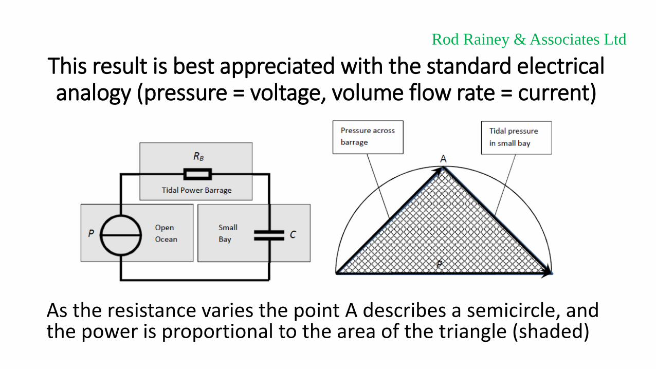
This result is best appreciated with the standard electrical analogy (pressure = voltage, volume flow rate = current)
As the resistance varies the point A describes a semicircle, and the power is proportional to the area of the triangle (shaded)
Rod Rainey & Associates Ltd
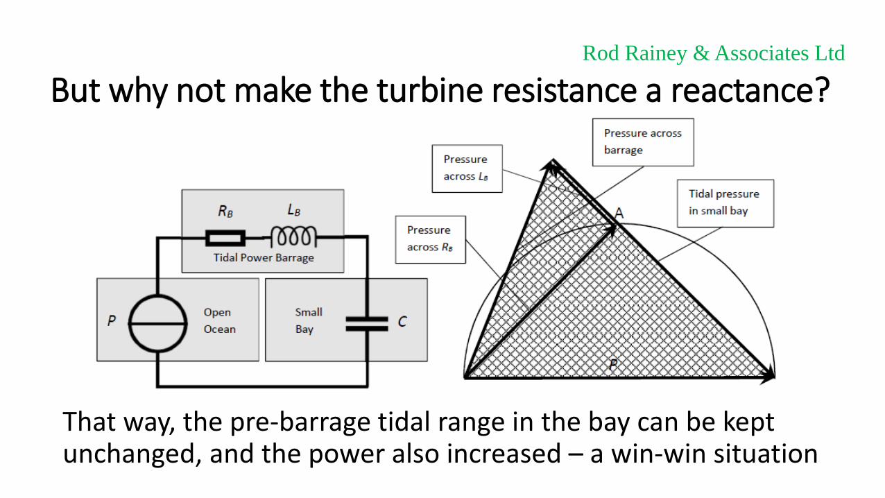
But why not make the turbine resistance a reactance?
That way, the pre-barrage tidal range in the bay can be kept unchanged, and the power also increased – a win-win situation
Rod Rainey & Associates Ltd

Required pressure-flow characteristic of turbine
Characteristic of resistive component (yellow), inductive component (blue) and combined characteristic (red/green). Red = pumping.
Rod Rainey & Associates Ltd

Power output (before conversion losses) over tidal cycle
The pumping power is surprisingly small – less than 4% of the generated power. The pumping energy is even less – only 0.65%
Rod Rainey & Associates Ltd

The breast-shot water wheel
The blades act like the vanes in a vane pump, not the paddles in a paddle-steamer. Unlike a turbine, when the wheel stops, so does the flow, as required at points “B” in the characteristic.
Rod Rainey & Associates Ltd

A 200-year-old concept, e.g. Claverton Pumping Station
Rod Rainey & Associates Ltd
Photos courtesy www..claverton.org

Recent application is small-scale hydropower in developing countries. Tests show high efficiency.
Rod Rainey & Associates Ltd
From G. Muller et.al., ICE J. Engineering Sustainability, Vol 157, paper 13806

Power take-off at Claverton Pumping Station
Rod Rainey & Associates Ltd

Gear drive, as in (most) wind turbines
Rod Rainey & Associates Ltd

Hydraulic power take-off for Severn Barrage
• A hydraulic power take-off, used on construction machinery and some wind turbines, functions like a gearbox with infinitely-adjustable gear ratio.
• Coupled to a synchronous generator/motor which runs at constant speed, it allows us to set any flow rate and hence follow the required elliptical characteristic
• No hydraulic motors exist for our size, so twin hydraulic rams with brake calipers can be used, alternately gripping a brake disc, like a strand jack.
Rod Rainey & Associates Ltd

For the Severn we need extra elements in the circuit
The reservoir has a resistance added to model seabed friction, giving it an overall impedance Z1, and the imperfect access to the open ocean gives it a source impedance Z2
Rod Rainey & Associates Ltd

Z1 and Z2 can be calculated from G. I. Taylor’s 1921 model
Rod Rainey & Associates Ltd
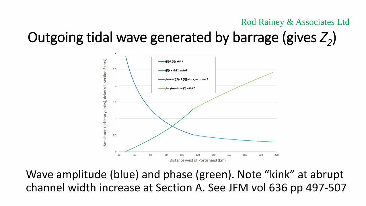
Outgoing tidal wave generated by barrage (gives Z2)
Wave amplitude (blue) and phase (green). Note “kink” at abrupt channel width increase at Section A. See JFM vol 636 pp 497-507
Rod Rainey & Associates Ltd

Annual-average power, before conversion losses
For a site between C and D, power = 6GW, or 4GW after conversion losses
Rod Rainey & Associates Ltd

Environmental impact, with head across barrage 0.6 ×pre-barrage tidal amplitude (range/2), see last slide
Rod Rainey & Associates Ltd

Young mammal in inter-tidal zone west of barrage Rod Rainey & Associates Ltd

Nash Point and 18 km line of barrage Rod Rainey & Associates Ltd
Nash PointHurlstone Point
Porlock

Hurlstone Point seen from above PorlockRod Rainey & Associates Ltd
Hurlstone Point

Jurassic Limestone (Lias) cliffs at Nash Point Rod Rainey & Associates Ltd
This formation extends under the sea almost to Hurlstone Point, as level bare rock ideal for piled foundations
Rod Rainey & Associates Ltd
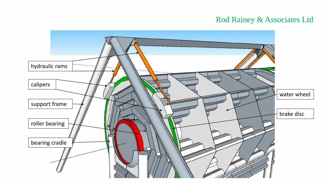
hydraulic rams
calipers
support frame
roller bearing
bearing cradle
water wheel
brake disc

Rod Rainey & Associates Ltd
cradle piles
support frame piles

Rod Rainey & Associates Ltd
SEA BED

Rod Rainey & Associates Ltd
SEA BEDLOW TIDE

Rod Rainey & Associates Ltd
HIGH TIDE

Barrage construction, installation, maintenance
• Plated steel construction, like a ship. Extensive use of corrugated plate, like the bulkheads in a modern tanker, to minimise fabrication cost. Wheel can also be rotated for fabrication, to avoid working at height.
• Wheel and cradle will float, to ease installation. Cradle piles fit into holes in rock seabed, pre-drilled through a template. Similar limestone is drilled in quarries for explosives, at rates of 10m/hr.
• All machinery in air and accessible by road, for ease of maintenance. Wheel, with bearings, can be floated out for maintenance
Rod Rainey & Associates Ltd
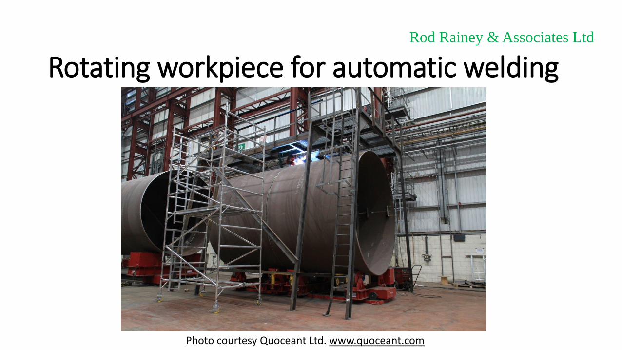
Rotating workpiece for automatic weldingRod Rainey & Associates Ltd
Photo courtesy Quoceant Ltd. www.quoceant.com

Rod Rainey & Associates Ltd
HIGH TIDE
Water wheel can be floated out and removed by an anchor-handling tug

Rod Rainey & Associates Ltd
HIGH TIDE
15mm plate. Drum used for buoyancy during float-out
50 m
30 m
20 mm plate

Stresses in water wheel bladesAssume corrugated wheel blades 10m wide with 1.111m wide corrugations in 15mm thick steel plate, and 2.5m head (0.025 MPa) pressure loading:
• Local bending stress in face = (0.025×1.1112/12)×0.0075/(0.0153/12) = 69 MPa
• Bending of 10m long corrugation = {(0.025×3×1.111×102/12)×1.111×√3/4}/
{2×1.111×0.015×(1.111×√3/4)2×(4/3)} = 32 MPa
• This compares with a Code fatigue stress range (at 108 cycles ≈ 200 years) of 70 MPa for plain steel, 30 MPa for Class E welded joint
Rod Rainey & Associates Ltd

Stresses around calipers
• Torque on water wheel at 2.5m head (0.025 MPa) = 0.025×10×50×10 = 125 MN-m
• Force on each caliper = (125/2)/15 = 4.2 MN
• Assuming 5m long caliper and 20mm thick disc, stress = 4.2/(5×0.02) = 42 MPa
Rod Rainey & Associates Ltd

Weight of steel in water wheel• Blades: 8×50×10×(4/3)×0.015×7.85 = 628 tonnes
• Drum: 50×10π×0.015×7.85 = 185 tonnes
• Internal bulkheads: 4×302×(π/4)×0.015×7.85 = 332 tonnes
• End bulkheads: 2×302×(π/4)×2×0.02×7.85 = 444 tonnes
• Total = 628+185+332+444 = 1600 tonnes
Rod Rainey & Associates Ltd

Rod Rainey & Associates Ltd
10mm plate 20mm (?) plate
30mm wall thickness piles

Rod Rainey & Associates Ltd
Plating continued underneath, for torsional strength, and also to allow cradle to be floated out as a barge, and then ballasted down into holes pre-drilled on the seabed through a template
10mm plate

Stresses in cradle platingAssume corrugated panels 10.5m wide with 0.8m wide corrugations in 10mm thick steel plate, and 2.5m head (0.025 MPa) pressure loading:
• Local bending stress in face = (0.025×0.82/12)×0.005/(0.013/12) = 80 MPa
• Bending of 10m long corrugation = {(0.025×3×0.8×10.52/12)×0.8×√3/4}/
{2×0.8×0.01×(0.8×√3/4)2×(4/3)} = 75 MPa
• This compares with a yield strength of 355 MPa – the large margin is typical of prudent conceptual design practice.
Rod Rainey & Associates Ltd

Weight of steel in cradle and support structure• Plating: {55×(13+5)+11×20}×2×(4/3)×0.01×7.85 = 253 tonnes
• Piles: {2×70+4×30}×2π×0.03×7.85 = 385 tonnes
• Cross-beam: 60×(2×2+2×√2)×0.02×7.85 = 64 tonnes
• Breast and filler plates: (55×13×0.02+10×30π×0.01)×7.85 = 186 tonnes
• Total = 253+385+64+186 = 900 tonnes
Rod Rainey & Associates Ltd

Comparison with Beatrice offshore wind farm
• Beatrice wind turbines are 7MW max, so about 3MW annual-average. By comparison, annual-average power of single waterwheel is 4,000/250 = 16 MW.
• Beatrice wind turbines weigh about 300 tonnes, and have 865 tonne substructures, anchored by 500 tonnes of piles. So 1650 tonnes in all. By comparison, water wheels weigh 1600+900 = 2500 tonnes.
• So Severn Barrage is less than one third the steel weight, per unit energy. Installation and maintenance also easier – no cranes needed.
Rod Rainey & Associates Ltd

Thank you for listening
Rod Rainey & Associates Ltd