trimod besta level switch types xa… and xb… with microswitch · page 2 of 8 ltb001en / 2011.12...
TRANSCRIPT

www.besta.ch Page 1 of 8 LTB001EN / 2011.12
Operating instruction LTB001EN
Trimod Besta Level Switch types XA… and XB… with microswitch for use in potentially explosive atmospheres acc. t o directive 94/9/EC
Contents 1. Safety instructions 2. Conformity of standards 3. Technical data 4. Installation and initial start-up 5. Maintenance 6. Replacing the switch insert 7. Fire protection 8. Disposal 9. EC-Declaration of conformity Legend
Information: Application hints and important information. To be followed for optimal function. Attention: Requirements and prohibitions to prevent damages, especially to material and the environment. Danger: Dangerous situation that can lead to injury and death if instructions are not followed.

www.besta.ch Page 2 of 8 LTB001EN / 2011.12
1. Safety instructions The operating manual must be read and understood before installation. If you are uncertain on any point, please contact Besta AG, Switzerland. The electrical connection may only be carried out by qualified personnel who have been authorised by the operator. All attached cables and cable bushings must comply with the requirements of EN 60079-0 Appendix A: explosion-proof cables and cable entries. The supply voltage may only be applied after the cover has been closed. Please ensure that you always observe the special regulations concerning work on explosion-proof devices and during work in potentially explosive atmospheres at the operators site. Every Trimod Besta level switch must be selected by qualified, trained personnel in accordance with the specifications stipulated by the customer. These specifications must be kept by the operator in a safe place, together with the operating manual, the customer-specific designation and the type number (see type plate). In the event of any deviation of the physical quantities (pressure, temperature, density, etc.) from the original specification, the suitability of the level switch must be checked again by qualified, trained personnel or by the manufacturer, with regard to the new specifications. Process vessels / float chambers must be brought to atmospheric pressure before work is carried out and must be appropriately vented. The devices may, under no circumstances, be used as a support aid or as a security fixture for equipment structures or for persons.
2. Conformity of standards Trimod Besta level switches conform with the requirements of Type XA… EN 60079-0, EN 60079-1, EN 60079-7, EN 60079-26 Type XB… EN 60079-0, EN 60079-1, EN 60079-11, EN 60079-26
3. Technical data Electrical connection The electrical connection should be carried out in accordance with the regulations for explosion proof devices. Not suitable for the switching of motor loads and incandescent lamp loads. The device is not protected against excess current.
Type XA… Explosion protection [Ex] II 1/2 G Ex de IIC T6 EC Type-examination EPS 09 ATEX 1238 X CE designation CE 0081 Supply voltage type XA… max. 5A / 250VAC 50 / 60Hz 0,25A / 250VDC Switching capacity type XA… with AC (Alternating cu rrent)
Max. switching current
Resistive load Max. switching current
Inductive load
250 V AC 5 A 5 A
30 V AC 5 A 5 A

www.besta.ch Page 3 of 8 LTB001EN / 2011.12
Switching capacity type XA… with DC (Direct curren t)
Max. switching current
Resistive load Max. switching current
Inductive load
250 V DC 0,25 A 0,03 A
125 V DC 0,5 A 0,06 A
75 V DC 1 A 1 A
30 V DC 5 A 5 A
Type XB… Explosion protection [Ex] II 1/2 G Ex ia d IIC T6 EC Type-examination EPS 09 ATEX 1238 X CE designation CE 0081 Supply voltage type XB… For use in intrinsically-safe circuits only! Maximum values Ii = 0.5 A Ci, Li ≈ 0 nF, 0 µH The product of current and voltage should not exceed 0.12 VA, otherwise the gold contacts could be permanently damaged. Special conditions for safe use min./max. ambient temperature TA (acc. to EN 60079-0 : -20°C to 40°C)
XA… / X2A… / X5A… XAA… / X2AA… / X5AA…
XB… / X2B… / X5B… XBB… / X2BB… / X5BB…
XU…A… / X5U…A… XU…AA… / X5U…AA…
XU…B… / X5U…B… XU…BB… / X5U…BB…
Temperature range ambient TA -40°C … 80°C -30°C … 80°C
min./max. operating / medium temperature T0
XA… / X2A… / X5A… XAA… / X2AA… / X5AA…
XB… / X2B… / X5B… XBB… / X2BB… / X5BB…
XU…A… / X5U…A… XU…AA… / X5U…AA…
XU…B… / X5U…B… XU…BB… / X5U…BB…
Temperature range medium T0 -40°C … 330°C -30°C … 80°C
Temperature range medium T0 with float module FEP coated
-40°C … 200°C -30°C … 80°C
The rated cross-section of the conductor to be considered here must be at least 0,5 mm². Connection cables may not be bared for a distance of more than 3 mm from the terminal screw. Wire end ferrules must always be used. The cable gland is not a component of the supply, except for types XU…

www.besta.ch Page 4 of 8 LTB001EN / 2011.12
4. Installation and initial start-up During installation, the correct operating position must be observed.
The float must be able to move freely over the whole range of movement and must not be restricted by the tanks walls or by fittings in the tank. Installation positions that are subject to turbulence impair the function and should always be avoided. Process connection flange - Industrial range For switches in the industrial range with flanges according to DIN, ANSI, etc., the seals (¹) and connecting studs (¹) that are used must correspond to the industry standard for material, pressure class and type of seal and must be tightened to the corresponding tightening torques. (¹) not a component of the supply. In case of uncertainty on any point, refer to the corresponding standard or consult the manufacturer. Process connection flange - Standard range For switches of the standard range PN 25 (360 psi), corresponding seals are supplied with the unit. Minimum tightening torques and tightening sequence:
Flange
D
Seal
Stud Carbon steel
Stud Stainless steel
01 / 011 92 mm Garlock Blue Gard 3000 18 Nm (²) 22 Nm (²)
(²) Data refer to lubricated studs Connecting 1. Loosen the cover screws, remove the protective plug from the cable entry and fit the cable gland. 2. Insert the cable and connect to the wires according to the connection diagram (see inside the
housing cover and instructions). All terminal connections are self-opening. Connect the earth A inside the housing) and equipotential bonding B (external, near to cable entry).
3. First close the cover and then apply the supply voltage!

www.besta.ch Page 5 of 8 LTB001EN / 2011.12
Connection diagram
Type Function Connection diagram
XA…, XB… X2A…, X2B… X5A…, X5B… XU…A…, XU…B… X5U…A…, X5U…B…
1 piece 1-pole
changeover switch (SPDT)
XAA…, XBB… X2AA…, X2BB… X5AA…, X5BB… XU…AA…, XU…BB… X5U…AA…, X5U…BB…
2 pieces 1-pole
changeover switch (2x SPDT)
5. Maintenance
Level switches must be periodically tested and cleaned, at least once annually.
Procedure: 1. Before opening the housing, disconnect the supply voltage; electric shocks can be life threatening. 2. Process vessels / float chambers must be brought to atmospheric pressure before work is
carried out and must be appropriately vented. If necessary, lower the fill level. If the switch is mounted in a chamber, close the corresponding shut-off valves and, depending on the requirement, empty or vent the chamber.
3. Loosen the flange connection and remove the switch. 4. Check the float and mechanism for damage and contamination. 5. Remove deposits and metal particles by means of suitable and approved methods. Care must be
taken to ensure that no mechanical damage occurs as a result of the cleaning. 6. In the case of floats with protective bellows, the bellows must be removed before cleaning and
should be cleaned separately, both internally and externally. 7. Check the float and mechanism for complete deflection, as well as for smooth and unrestricted
operation. 8. In the event that it becomes necessary to replace individual components, please note that only
original spare parts, split pins, float, switch module, etc. may be installed. 9. After completion of the cleaning / inspection work, the switch module must be checked for
correct function by means of an acoustic continuity tester or similar device with simultaneous deflection of the float, followed by recording in the inspection log book.
10. In order to guarantee the absence of leaks between process vessel / float chamber, the flange
seal must be replaced after each dismantling. 11. After carrying out the inspection work, the device is re-fitted at the intended location.
2a
1a 1n
2n
A
3n 3a
B

www.besta.ch Page 6 of 8 LTB001EN / 2011.12
6. Replacing the switch insert Defective switch elements must be replaced by new, works-tested units. The case of uncertainty on any point, please contact the local Trimod Besta agent or the manufacturer. Replacing the switch insert Important notes: The switch does not have to be removed from the process vessel in order to replace the switch element. Repairs to explosion-proof level switches may only be carried out by specialists who have been approved by the relevant local authorities. The replacement of a switch insert must be recorded accordingly. Procedure: 1. Observe chapter 1 „Safety instructions“ 2. Follow the installation instruction LTI005EN «Replacement switch insert type X…»
7. Fire protection Trimod Besta level switches must be protected against external fires.
8. Disposal Trimod Besta level switches are free of asbestos or otherwise hazardous materials. Disposal to be carried out according to environmental and local regulations.
9. EC-Declaration of conformity EC-Declaration of conformity acc. to directive 94/9/EC for Trimod Besta Level Switch type XA… see page 7 EC-Declaration of conformity acc. to directive 94/9/EC for Trimod Besta Level Switch type XB… see page 8
Ackerstrasse 45 | CH-8610 Uster | Switzerland Phone +41 43 399 15 15 | Fax +41 43 399 15 00 Subject to technical modification
EG-Konform ATEX XA_Dez11_ohne Logo.doc
EG-Konformitätserklärung gemäss den Bestimmungen der Richtlinien 94/9/EG
EC-Declaration of Conformity following the provisions of directives 94/9/EC
Wir, die nachstehend genannte Firma We, the company specified below
Besta AG, Ackerstrasse 45, CH-8610 Uster, Schweiz / Switzerland erklären in alleiniger Verantwortung, dass das nachfolgend erwähnte Produkt declare under its sole responsibility that the product
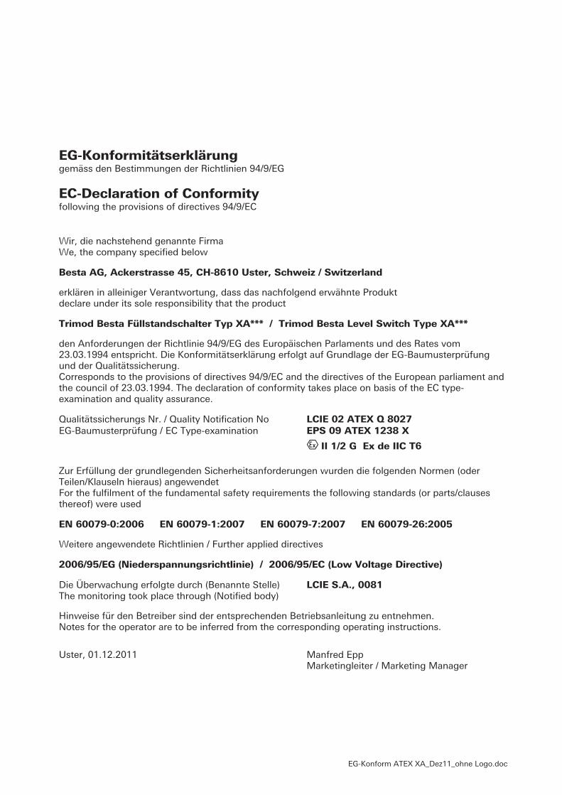
Trimod Besta Füllstandschalter Typ XA*** / Trimod Besta Level Switch Type XA*** den Anforderungen der Richtlinie 94/9/EG des Europäischen Parlaments und des Rates vom 23.03.1994 entspricht. Die Konformitätserklärung erfolgt auf Grundlage der EG-Baumusterprüfung und der Qualitätssicherung. Corresponds to the provisions of directives 94/9/EC and the directives of the European parliament and the council of 23.03.1994. The declaration of conformity takes place on basis of the EC type-examination and quality assurance.
Qualitätssicherungs Nr. / Quality Notification No LCIE 02 ATEX Q 8027 EG-Baumusterprüfung / EC Type-examination EPS 09 ATEX 1238 X
� II 1/2 G Ex de IIC T6
Zur Erfüllung der grundlegenden Sicherheitsanforderungen wurden die folgenden Normen (oder Teilen/Klauseln hieraus) angewendet For the fulfilment of the fundamental safety requirements the following standards (or parts/clauses thereof) were used
EN 60079-0:2006 EN 60079-1:2007 EN 60079-7:2007 EN 60079-26:2005 Weitere angewendete Richtlinien / Further applied directives
2006/95/EG (Niederspannungsrichtlinie) / 2006/95/EC (Low Voltage Directive)
Die Überwachung erfolgte durch (Benannte Stelle) LCIE S.A., 0081 The monitoring took place through (Notified body) Hinweise für den Betreiber sind der entsprechenden Betriebsanleitung zu entnehmen. Notes for the operator are to be inferred from the corresponding operating instructions.
Uster, 01.12.2011 Manfred Epp Marketingleiter / Marketing Manager

EG-Konform ATEX XB-XI_Dez11_ohne Logo.doc
EG-Konformitätserklärung gemäss den Bestimmungen der Richtlinien 94/9/EG
EC-Declaration of Conformity following the provisions of directives 94/9/EC
Wir, die nachstehend genannte Firma We, the company specified below
Besta AG, Ackerstrasse 45, CH-8610 Uster, Schweiz / Switzerland erklären in alleiniger Verantwortung, dass das nachfolgend erwähnte Produkt declare under its sole responsibility that the product
Trimod Besta Füllstandschalter Typ XB*** und XI*** Trimod Besta Level Switch Type XB*** and XI*** den Anforderungen der Richtlinie 94/9/EG des Europäischen Parlaments und des Rates vom 23.03.1994 entspricht. Die Konformitätserklärung erfolgt auf Grundlage der EG-Baumusterprüfung und der Qualitätssicherung. Corresponds to the provisions of directives 94/9/EC and the directives of the European parliament and the council of 23.03.1994. The declaration of conformity takes place on basis of the EC type-examination and quality assurance.
Qualitätssicherungs Nr. / Quality Notification No LCIE 02 ATEX Q 8027 EG-Baumusterprüfung / EC Type-examination EPS 09 ATEX 1238 X
� II 1/2 G Ex ia d IIC T6…T2
Zur Erfüllung der grundlegenden Sicherheitsanforderungen wurden die folgenden Normen (oder Teilen/Klauseln hieraus) angewendet For the fulfilment of the fundamental safety requirements the following standards (or parts/clauses thereof) were used
EN 60079-0:2006 EN 60079-1:2007 EN 60079-11:2007 EN 60079-26:2005 Weitere angewendete Richtlinien / Further applied directives
2006/95/EG (Niederspannungsrichtlinie) / 2006/95/EC (Low Voltage Directive) 2004/108/EG (EMV-Richtlinie) / 2004/108/EC (EMC Directive)
Die Überwachung erfolgte durch (Benannte Stelle) LCIE S.A., 0081 The monitoring took place through (Notified body) Hinweise für den Betreiber sind der entsprechenden Betriebsanleitung zu entnehmen. Notes for the operator are to be inferred from the corresponding operating instructions.
Uster, 01.12.2011 Manfred Epp Marketingleiter / Marketing Manager