trianco - boiler manuals · there is no manual adjustment. note: the phial is to be located in a...
TRANSCRIPT

To be retained by householder
USER, INSTALLATIONCOMMISSIONING & SERVICING
INSTRUCTIONS
BALANCED FLUEOIL FIRED CENTRAL HEATING BOILERS
TRIANCOEuroStar WM 50/65In The Wall Boiler
BED 92/42 EECEMC 89/336 EEC

HEALTH AND SAFETY
INFORMATION FOR THE INSTALLER AND SERVICE ENGINEERS
Under the Consumer Protection Act 1987 and the Health and Safety at Work Act 1974, it is arequirement to provide information on substances hazardous to health (COSHH Regulations1988).
The Company takes every reasonable care to ensure that these products are designed and con-structed to meet these general safety requirements, when properly used and installed.
To fulfil this requirement products are comprehensively tested and examined before despatch.
This appliance may contain some of the items below.
When working on the appliance it is the Users/Engineers responsibility to ensure that any neces-sary personal protective clothing or equipment is worn appropriate to parts that could be consid-ered as being hazardous to health and safety.
INSULATION AND SEALS
Glass Rope, Mineral Wool, Insulation Pads, Ceramic Fibre, Glass Insulation.
May be harmful if inhaled. May be irritating to the skin, eyes, nose or throat. When handling avoidinhalation and contact with eyes. Use (disposable) gloves, face masks and eye protection.
After handling wash hands and other exposed parts. When disposing, reduce dust with waterspray, ensure parts are securely wrapped.
GLUES, SEALANTS & PAINT
Glues, Sealants and Paints are used in the product and present no known hazards when used inthe manner for which they are intended.
KEROSENE & GAS OIL FUELS (MINERAL OILS)
1. The effect of mineral oils on the skin vary according to the duration of exposure.
2. The lighter fractions also remove the protective grease normally present on the surface of theskin rendering the skin dry, liable to crack and more prone to damage caused by cuts and abrasions.
3. Skin rashes (oil acne). Seek immediate medical attention for any rash, wart or sore developing on any part of the body, particularly the scrotum.
4. Avoid as far as possible any skin contact with mineral oil or with clothing contaminated with mineral oil.
5. Never breathe any mineral oil vapours. Do not fire the Burner in the open i.e. out of the Boileras a misfire will cause unburnt oil vapours.
6. Barrier cream containing lanolin such as Rosalex Antisolv, is highly recommended together with a strict routine of personal cleaning.
7. Under no circumstances should mineral oils be taken internally.
CONTENTSPAGE
1. USER INSTRUCTIONS 1/2After sales service information 3
2. INTRODUCTION 4
3. TECHNICAL INFORMATION 5
4. INSTALLATION 6Regulations 6Health and Safety 6Siting the Boiler 6/7
5. OIL SUPPLY 9Oil storage tank - Steel and Plastic 9Oil supply line 9Single pipe oil supply 9Two pipe oil supply 9Oil De-aerator - Single pipe supply 9
6. ELECTRICAL 13
7. SERVICING 16Oil Tanks 16Line Filters 16Boiler 16
8. COMMISSIONING 17Procedure 17Handing over 17
9. FAULT FINDING 18/19
10. SPARES 20/21

1
FIG. 1
HIGH LIMIT THERMOSTAT
INDICATOR LIGHTS
OVERHEAT (RED)
MAINS ON (GREEN)
BOILER CONTROL THERMOSTAT
The boiler control thermostat enables you to select thetemperature of the water leaving the boiler. It is calibrat-ed between High and Low in five intermediate settings,corresponding to a temperature range of 82° C (high) to55° C (low).
Set the temperature by turning the knob to the requiredtemperature. However, the installer should take into con-sideration that the return water temperature must notdrop below 56.2° C when the appliance is up to full oper-ating temperature.
The thermostat is switched off when the knob is turnedfully anti-clockwise with pointer opposite ‘O’
HIGH LIMIT THERMOSTAT(Hand Reset)
The high limit thermostat is factory set and requires noadjustment. Should the boiler thermostat malfunction,the limit thermostat will take over and shut down the boiler,thus leaving the overheat neon light illuminated (see Fig1 for position).
If the limit thermostat operates frequently, consult yourService Engineer as there may be a fault in the system.
To reset the limit thermostat, remove all the inside doorpanel and push reset button.
Note: The limit thermostat can only be reset when thewater temperature has dropped at least 20°C.
SYSTEM CONTROLS
ROOM THERMOSTAT
The room thermostat should not be positioned near asource of heat such as a radiator or exposed to the sunas this will cause the central heating to switch off beforethe room is up to temperature. Follow the manufacturer’sinstructions for best siting position for the thermostat.
1 USERS INSTRUCTIONSAll boiler controls are located behind the front casingdoor panel. This is opened by pulling the bottomedge towards you.
The Trianco EuroStar WM 50/65 In The Wall Boilers havebeen designed and constructed to give years of troublefree service and these instructions are provided to assistyou in obtaining the best performance with the least trou-ble and cost.
The boiler is fully automatic in operation and requireslittle attention other than the setting of the thermostat andany system controls such as a room thermostat andtime-switch.
TO FIRE THE BOILER
1 Before firing the boiler, ensure the system is full ofwater, there is sufficient oil in the storage tank and allvalves are open.
2 Check that the Time-switch/Programmer (if fitted) isON and the room thermostat is calling for heat.
3 Set the boiler thermostat to the desired temperature.
4 Switch on the electrical supply to the boiler and theburner should fire after a few seconds of fan prepurge.
5 Set the Time-switch/Programmer (if fitted) to the timesand programme required.
6 The boiler will now operate automatically, cutting inand out according to the heat demand.
TO STOP THE BURNER
The burner may be stopped by turning the Boiler ControlThermostat fully anti-clockwise to the OFF position ‘0’.
If the boiler is to be off for a long time, it is recommendedthat the mains supply to the boiler is switched off or theTime-switch/Programmer (if fitted) is switched to the OFFposition.
BOILER CONTROLTHERMOSTAT
CONTROLS LOCATED BEHINDFRONT FASCIA PANEL

2
Boiler Model
Serial Number
Fuel Type
Oil Tank Capacity
Oil Supplier 1
Oil Supplier 2
TIME-SWITCH PROGRAMMER
When choosing the operating times for your boiler, it isuseful to remember that central heating usually takesbetween half an hour before is becomes effective.
It is suggested that the Time-switch/Programmer is set tobring on the heating about an hour before heating isrequired.
It is also worth noting that the heating system will usuallyremain effective for up to half an hour after boiler shut-down. The timer can therefore be switched off earlier asan economy measure.
FROST PROTECTION
The boiler is fitted with a frost thermostat, which will acti-vate the burner should ambient temperature fall to 5° C,the thermostat will automatically cut off on temperaturerise. There is no manual adjustment.
Note: The phial is to be located in a clip provided on therear of the boiler mounting plate.
If the system is shut down for a long period during verycold weather, it is advisable to completely drain the system.However, frequent draining should be avoided, especiallyin hard water areas, as this could lead to scaling of theboiler waterways.
SHUTTING DOWN FOR THE SUMMER
If the boiler is shut down for the summer months, it isadvisable to have it serviced and thoroughly cleaned assoon as possible to minimise corrosion of the heatingsurfaces.
OIL
The recommended oil for your boiler is 28 sec. Kerosene(BS 2869: Class C2)
OIL TANK
Always ensure the tank is topped up at regular intervals,do not wait until the tank is nearly empty before refilling,
otherwise sludge and water could be sucked into the oilpipe to affect the burner’s operation and reduce pump life.
After a delivery of oil, it is recommended that the oil isallowed to settle in the tank for about half an hour beforerestarting the burner.
Sludge and water caused by condensation should bedrawn off at the drain-cock annually.
SIMPLE FAULT FINDING
If the burner fails to start for no apparent reason, makethe following checks before calling your ServiceEngineer.
1 Check for failure in the electrical supply, e.g a power cut.
2 Check that there is adequate oil in the tank and theshut-off valves are open.
Note: If the boiler has been off as a result of a powerfailure, it will probably be necessary to re-set the Time-switch/Programmer to the correct time unless it has abuilt-in power reserve.
SERVICING
To ensure efficient and reliable operation of the boiler, itis essential that the oil burner is initially commissioned byan OFTEC trained and registered engineer and anannual service is given thereafter.
Notes:ELECTRICAL SAFETY CHECKS SHOULD BECARRIED OUT BY A QUALIFIED ELECTRICALENGINEER
(a) It is the responsibility of the Installer to ensureproper commissioning is carried out.
(b) It is a requirement of the boiler’s guarantee andany extended warranty that an annual serviceis carried out by a qualified engineer.
Commissioning Engineer’sSignature...........................................................................
Company Name................................................................
..........................................................................................
Address.............................................................................
..........................................................................................
..........................................................................................
Tel No:...............................................................................

TRIANCOCUSTOMER AFTER SALES SERVICE INFORMATION
SERVICE CENTRETel: 0114 257 2300
Service Desk Ext. 232Customer Services Manager Ext. 232
TECHNICAL SUPPORTTechnical Helpline
Direct Line 0114 257 2301Hours of business Monday to Friday 8.30am-5.00pm
3
NOTE: Burner nozzles are currently guaranteeduntil the first service.
Over 50% of all service calls made arefound to have no appliance fault.
What to do in the event of an appliancefault or breakdown:
Step 1: Always contact your installer or commissioning engineer in the first instance, who mustthoroughly check all his work PRIOR torequesting a service visit from Trianco.
Step 2: If your appliance has developed an in-guaranteefault your installer should contact TriancoService Centre for assistance.
What happens if my installer/engineer isunavailable?
Step 3: Contact Trianco Direct. We will provide you withthe name and telephone number of our ServiceAgent. However, a charge may apply if the faultis not covered by the appliance guarantee (payment will be requested on site by our independent Service Agent).
PLEASE NOTE:Unauthorised invoices for attendance and repair workcarried out on this appliance by any third party will not beaccepted by Trianco.
A step by step guide to reporting a faultwith your appliance
A qualified field SERVICE ENGINEER is available toattend a breakdown or manufacturing fault occurringwhilst the appliance is under guarantee.
A charge will be made where:
• Our Field Service Engineer finds no fault with theappliance
or
• The cause of a breakdown is due to other parts of theplumbing/heating system (including oil line/lack ofoil), or with equipment not supplied by Trianco.
or
• Where the appliance falls outside the 12 month guarantee period (see terms and conditions enclosed).
or
• The appliance has not been correctly installed,commissioned or serviced as recommended (seecommissioning, installation and servicinginstructions)
or
• The breakdown occurs immediately following anannual service visit. In this instance your appointed Service Agent must check all his work PRIOR torequesting Trianco to attend.

2 INTRODUCTIONTrianco EuroStar WM 50/65 In The Wall Boilers aredesigned to operate with high efficiency and clean com-bustion on open vent fully pumped systems and sealedsystems.
Models are supplied as standard to use kerosene 28 sec-ond class C2 fuel only.
IMPORTANT SAFETY NOTES
Read these instructions before installing your boiler.
The heating system must comply with the latest editionsof British Standards 5410 and The Building Regulation,and Electrical Wiring Regulations BS 7671.
Please note: It is essential in the interest of boiler effi-ciency and reliable performance that once the boiler hasbeen installed it is first commissioned by an OFTECregistered engineer. It is the responsibility of the installerto ensure that the boiler is commissioned.
Always switch off the electrical supply before removingany of the covers for cleaning.
If any part of the boiler of its flue is modified, then theguarantee/warranty will be invalidated.
We recommend that you keep these instructions in aplace near your appliance for easy reference.
Important Notice:To comply with regulations in force, your new boiler must be installed and commissioned
by an OFTEC-registered engineer. The installation must also comply with currentBuilding Regulations, Part L.
Failure to meet the terms of these requirements may invalidate your guarantee.
The Trianco EuroStar WM 50/65 In The Wall Boilers have been designed to conform to European Directive/Standards BED 92/42 EEC, LVD EN 60335-1 EMC 89/336/EEC
THE PERSON(S) WHO INSTALLS THIS APPLIANCE, COMMISSIONS, SERVICES OR CARRIES OUTANY REMEDIAL WORK, I.E. ELECTRICAL FAULT FINDING, MUST HAVE SUITABLE
ENGINEERING QUALIFICATIONS.
4

3 TECHNICAL INFORMATION
Technical Specifications
EuroStar Boiler Models WM 50 WM65
Rated Input (Btu/h) 56,200 73,610(kW) 16.4 21.6
Rated Output (Btu/h) 50,000 65,800(kW) 14.7 19
Oil Burner Model See burner details leaflet See burner details leaflet
Weight (empty) (kg) 49 49 (lb) 108 108
Water content (litre) 17 17(gal) 3.75 3.75
Flow & return sockets (in.) 22 Compression 22 Compression
Flue Gas Temp. °C 200 200
Max. operating pressure (bar) 3 3(psi) 43.5 43.5
Test Pressure (bar) 4.5 4.5(psi) 65.3 65.3
Water side resistance10° (mbar) 23 23
(in. w.g.) 9.2 9.220° (mbar) 6.4 6.4
(in. w.g.) 2.5 2.5
Starting Current (amp) 3.5 3.5
Running Current (amp) 0.77 0.77
Control Thermostat - Adjustable between 55 °C and 82 °C
Limit Thermostat - (Hand reset)
Frost Thermostat -Standard
Casing Finish -Internal - Stove enamelled white, with coloured fascia trim
Casing Finish -External Stove enamelled black
Thermal Insulation Insulated with fibre glass, reinforced with aluminium foil
Optional Extras Terminal Grille KitDecor Mounting Panel
Electrical Supply - 230v ~ 50 Hz
Electrical Rating 1PX3
Current 5 Amp
5

Clearance and Service Access
When siting the boiler, ensure adequate clearance isallowed internally and externally for future servicing.
Unpacking the Boiler
a) Remove the front door (white painted) and move toa safe place to avoid damage.
b) Remove the outer ducting door, (black painted),remove packages within ducting chamber containing:
1. Flue pipe assembly
2. Control panel front and rear
3. Oil line kit
4. Screw pack and gasket
5. Boiler top front bottom insulation (one piece)
All items should be stored in a safe place
Remove baffle cassette and internal baffle - see Fig. 12,together with burner. Store carefully to avoid damage.
c) Wall duct assembly can now be removed inpreparation for fitment into wall (assembly includesinner wall plate)
All other components can be left on the pallet untilrequired.
Assembly Procedure
The maximum wall thickness for the boiler is 20'' (508mm)and minimum 4 1/2'' (114mm)
General:
The external Eurostar must be installed in the correctorder.
Please study the instructions before commencing.
The wall to be used for mounting must be a load bearingexternal. Surfaces, both external and internal should beeven so as to ensure a flush fit of the inner wall duct assembly.
4. INSTALLATIONRegulation
Installation of the boiler must comply with the followingBritish Standards and Regulations:
BS 5410: Part 1 - Code of Practice for Oil Firing
BS 5449 - Forced Circulation Hot Water Central HeatingSystems.
The Building Regulations; Part ‘J’ (England and Wales)Part ‘F’ Section 111 (Scotland) Part ‘L’.
The Control of Pollution (Oil) RegulationsCurrent I.E.E. RegulationsLocal Water Undertakings By-lawsOFTEC Installation Requirements for Oil Fired Boilersand Oil Storage Tanks
Health And Safety At Work Act
The installer should be aware of his responsibilities underthe Act and provide, where necessary, appropriateprotection for persons carrying out the installation.
In the interest of safety, the boiler should be installed andcommissioned by an OFTEC trained and registeredengineer.
ELECTRICAL WORK SHOULD BE CARRIED OUT BY AQUALIFIED ELECTRICAL ENGINEER
A useful guide to Safe Working Practices for Oil FiringTechnicians is published by OFTEC.
Siting The Boiler
Sound Levels
The following aspects should be considered beforeinstalling:
a) Some people are particularly sensitive to even lownoise levels so this aspect should be discussed withthe householder.
b) Low level terminals produce some exhaust noise,so care should be taken when siting adjacent to neighbouring property.
6
EXTERNAL DIMENSIONS INTERNAL DIMENSIONSTHROUGH THE WALLDIMENSIONS
65 Min
65 Min
45
4522mm FlowReturn
400
200 Ctrs.
Mains Cable Entry
Mains Cable Entry
300114 (41/2'')508 (20'')
1000
MIN
715
585
460
370
673
130
FIG. 2 ALL DIMENSIONS IN MM UNLESS OTHERWISE STATED
40

When locating the boiler, care should be taken in respectof the flue terminal which should be within the parameterslaid down within Fig 3
Due care and attention is required when siting the boilernot only during installation but for subsequent servicing.The black outside casing of the boiler shall not be lessthan 1 metre form the ground. A sensible maximumheight for installation is 2.5 metre from the terminal.Boilers installed above this height must have provisionmade for the health and safety of the service engineer.
Modern boilers are designed to operate at low noise levels.However, when positioning your boiler it is notrecommended to have the terminal facing a neighbour’sproperty or patio etc. It should be positioned to avoidproducts of combustion entering the building. See fig. 3
a) With the template provided, mark out the proposed hole in the chosen wall. The dimensions allow for atolerance of 5mm all round. It is recommended thata cutting disc is used to remove surplus brick andblockwork; this will ensure a uniformed apertureopening. Care should also be taken to ensure thatthe prepared aperture is parallel.
b) Insert inner wall duct together with internal mountingplate through aperture in wall, hold centre and markfixing points (8) through holes in boiler mountingplate, drill (DIA 12 x 50 DEEP) and plug using screwssupplied. Affix assembly to wall, leaving screw looseto allow fitment of external duct.
c) Insert external duct over internal duct, holes to bottom.Adjust from wall thickness ensuring a minimum of40mm from wall face to front of sleeve; this is toallow for the fitment of oil line bulkhead fittings,valves and combustion air valves. On completion,secure all screws. Slide trim over sleeve, mark anddrill holes. 3-holes 12 Dia x 50mm deepdeep. Before fixing trim to wall, ensure wall is madegood and finally secure trim to wall. Silicone shouldalso be applied to area. See Fig. 2
CAUTION:
The heat exchanger weighs 49kg max, and requirestwo people to lift into position.
When fitted, the heat exchanger is secured in place by 3 x M8 flange nuts.
Water Connection
The boiler has two 22mm compression connections iden-tified on wall frame (supplied with nut and olive). Lefthand return right hand flow (viewed form inside building/dwelling).
There is also a 1/2'' BSP drain cock tapping located onthe bottom front of heat exchanger (viewed from outsidebuilding/dwelling).
The boiler must be used on a fully pumpedsystem only.
7
Note (1) The terminal should be positioned so as to avoid products of combustion entering the building.
Note (2) If the terminal is less than 2 metres above the ground level, balcony or place to which anyperson has access, the terminal must be protected by a guard.
Note (3) If the terminal is fitted within 850mm of plastic or painted gutter or within 450mm of painted eaves a heat protection shield should be fitted to the underside of the gutter of eaves.
Note (4) The flue must be positioned so that it does not cause nuisance and permits the dispersal of combustion products.
RECOMMENDED MINIMUM DISTANCESFOR TERMINAL POSITION
FIG. 3 TERMINAL POSITION
Location Minimum Distance (mm)
A Directly below an opening, window or air brick 1000B Horizontally to an opening, window, door air brick 1000C Below a gutter, drainpipe, eaves or balcony 600D From internal or external corners 600E Above ground level 1500F Vertically from a terminal on the same wall 1500G Horizontally from terminals on the same wall 750H From a vertical drain pipe 600J From a surface facing the terminal 3000K From a terminal facing the terminal 3000

FIG. 4 OIL LINE DETAILS
External
Baffles should be re-fitted ensuring correct position ofbaffle prior to inserting baffle cassette which is retainedby 4 x M6 wing nuts (see diagram, Fig 12).
External oil line connections should be made using theholes provided in base of outer sleeve.
Kit consists of:
2 x 1/4'' BSP Lock Nut1 x Female/Female Elbow 1/4'' BSP1 x 3/8'' x 1/4'' bulkhead fitting1 x 3/8'' None Return Valve
The boiler is factory fitted for 1 pipe oil line or de-aeration.Should it be necessary to employ a two-pipe system, seediagram on data sheet.
Important:
The isolating valve should be fitted on the flow pipe (seeoil line details, Fig 4) Fire valve sensing phial should belocated into clip provided above burner.
Burner can now be fitted prior to commissioning.
Ensure electrical lead from burner is plugged into thesocket connector on control panel.
When fitting the flue terminal, the actual terminal shouldprotrude through the external door a minimum of 65mm.Once the dimensions have been determined the flueshould be siliconed into position. NB The boiler can betest fired and subsequently commissioned with theexternal door removed.
8
FLEXIBLE OIL LINE
NONE RETURN VALVE
INNER DUCT ASSEMBLY
1/4'' BSP ELBOW

5 OIL SUPPLY
Oil
The oil burner is factory set to burn 28 sec. Kerosene toBS 2869.
Note: Only kerosene is permitted for low level fluedischarge.
Oil Storage Tank
Size and Location of Tanks
The tank should be large enough to allow for economicdeliveries and be located in the most unobtrusiveposition, having regard to the need of safety, filling, maintenance (if steel tank) and the head of oil required.
Whilst it is highly unlikely that a fire could start from a oiltank, it does however need to be protected from a fire thatmay originate in a nearby building. The tank should therefore not be located nearer than 1.8 metres, thebuilding wall must not have any openings other thansmall ventilation openings. The wall shall have a halfhour resistance to an internal fire and extend 1.8 metresfrom any part of the tank.
Alternatively, a non-combustible radiation barrier must beprovided which meets the requirements of BS 5410. Thisstandard applies to tanks up to a capacity of 3,400 litres.
Steel Tanks
Steel tanks should comply with the requirements ofBS799, Pt.5 and mounted on brick or block piers with awaterproof membrane between the piers and tank.
The tank should be fitted with the fill and vent connection(weather protected), a drain-off cock, shut off valve andan oil level indicator.
Plastic Tanks
Polyethylene tanks are now widely used because of theiradvantages over traditional steel tanks:
a) They do not need pier supports and can be mounteddirectly on any flat surface giving uniform support forthe tank base
b) They do not corrode and therefore never need painting.
c) They are easier to handle because of their weight.
d) They have a 10 year manufacturer’s guarantee.
Plastic tanks should be fitted with similar components tothose used with steel tanks.
Oil Supply Line
One long life flexible oil hose, filter and shut-off valve aresupplied with the boiler.
The oil shut-off valve should be fitted as shown to enablethe burner to be disconnected without undue loss of oil.The filter must be connected in the oil supply pipe and positioned outside the building. (Fig.4)
Fire Valve
a fire-valve must be fitted in the oil line outside the buildingwith its sensing phial positioned within the burnercompartments. clip is provided for retaining the phial above the burner.
All oil joints must be completely sealed and the total piperun thoroughly flushed out before connecting to the burner.No soldered joints are permitted in the oil line.The oil lines are fed into the boiler through pre-punchedholes in the bottom edge of the outer wall duct. An oil lineconnection kit is provided (see Fig 4)
Two pipe Oil Supply (Fig 5)
Where the bottom of the oil storage tank is below theburner, a two-pipe suction lift system may be necessary.
A spring loaded non-return valve must be fitted in thesuction line to stop the oil running back to the tank. A filter,shut-off valve and fire valve must be fitted in the line.
No valves are permitted in the return line which mustremain unobstructed at all times.
Notes:
The pump suction should not exceed 0.4 bar, otherwisedissolved gas will be released form the oil to affectcombustion.
The return pipe must end at the same level as the suctionoutlet to prevent loss of prime.
The outlet form the tank should be approximately 75mm(3 in) above the bottom to prevent sediment and waterbeing drawn into the supply pipe.
Oil De-aerator- Single Pipe Supply (Fig.6)
Where a two-pipe suction lift system is required , but thereturn pipe is too long, or impractical to run., a de-aeratorcan be used. The burner is piped as for a two-pipe systemup to the De-aerator but only a single pipe is required tobe run back to the oil storage tank. A non-return valve isnot required with this system. The burner is factory setfor two pipe systems.
The De-aerator, which should be fitted close to the boilerexternally, is available from most Builders Merchants andsome Oil Tank manufacturers.
Single Pipe oil Supply (Fig 7)
When the bottom of the oil supply tank is above the burner,a single pipe gravity system can be used. The oil supplypipe must be connected to the suction port on the burnerpump via the flexible hose. The return port must beblanked off with plug supplied and the C washer fitted(refer to burner instruction leaflet for more information).
When the tank is below the burner a none return valvemust be fitted, see Fig. 4
9
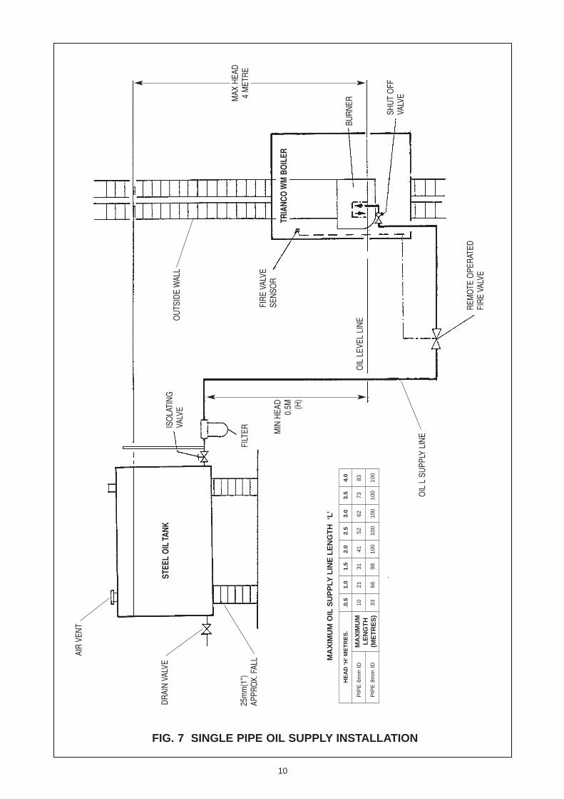
FIG. 7 SINGLE PIPE OIL SUPPLY INSTALLATION
HE
AD
‘H’M
ET
RE
S.
.0.5
1.0
1.5
2.0
2.5
3.0
3.5
4.0
PIP
E 6
mm
ID
1021
3141
5262
7383
PIP
E 8
mm
ID
3366
9810
010
010
010
010
0
MA
XIM
UM
OIL
SU
PP
LYL
INE
LE
NG
TH
‘L’
MA
XIM
UM
LE
NG
TH
(ME
TR
ES
)
10
AIR
VEN
T
DR
AIN
VAL
VEIS
OLA
TIN
GVA
LVE
FIR
E VA
LVE
SEN
SOR
REM
OTE
OPE
RAT
EDFI
RE
VALV
E
SHU
T O
FFVA
LVE
25m
m(1
'')AP
PRO
X.FA
LL
MIN
HEA
D0.
5M (H)
MAX
HEA
D4
MET
RE
BUR
NER
OIL
LEV
EL L
INEO
UTS
IDE
WAL
L
OIL
L S
UPP
LY L
INE
FILT
ER
TRIA
NCO
WM
BO
ILER
STEE
L O
IL T
ANK

FIG. 5 TWO PIPE OIL SUPPLY INSTALLATION
LIF
T ‘L
’ME
TR
ES
..0
.51.
01.
52.
02.
53.
03.
54.
0
PIP
E 6
mm
ID
4842
3630
2418
115
PIP
E 8
mm
ID10
010
010
094
7555
3616
PIP
E 1
0MM
ID
100
100
100
100
100
100
8840
MA
XIM
UM
OIL
SU
PP
LYL
INE
LE
NG
TH
‘L’
MA
XIM
UM
LE
NG
TH
(ME
TR
ES
)
11
SHU
T-O
FFVA
LVE
(ON
OIL
FLO
WLI
NE)
REM
OTE
OPE
RAT
EDFI
RE
VALV
E
NO
N R
ETU
RN
VAL
VEFI
TTED
IN V
ERTI
CAL
RU
N P
IPE
BUR
NER
OU
TER
WAL
LO
F H
OU
SE
FIR
E VA
LVE
SEN
SOR
OIL
LEV
EL
GAU
GE
DR
AIN
VA
LVE50
mm
(2'')
DIA
AIR
VEN
T
SAW
CU
T PI
PE (I
NSI
DE
TAN
K)TO
PR
EVEN
T SY
PHO
N
25m
m (1
'')AP
PRO
X.FA
LLFI
LTER
100
OIL
LIN
E
STEE
L ST
OR
AGE
TAN
K
H
OIL
RET
UR
N L
INE
L

FIG. 6 DE-AERATED OIL SUPPLY INSTALLATION
12
SHU
T-O
FFVA
LVE
(ON
OIL
FLO
WLI
NE)
BUR
NER
OU
TER
WAL
LO
F H
OU
SE
LEVE
L G
AUG
EVA
LVE
OIL
FIL
TER
DR
AIN
CO
CK
50m
m (2
'') D
IAAI
R V
ENT
OIL
STO
RAG
E TA
NK(P
LAST
IC T
ANK
SHO
WN)
SHU
T O
FF V
ALVE
DR
AIN
CO
CK
FIR
E VA
LVE
SEN
SOR
REM
OTE
OPE
RAT
EDFI
RE
VALV
E O
UTS
IDE
BUIL
DIN
G
NOTE
OIL
DE-
AER
ATO
R M
UST
BE
INST
ALLE
D U
PRIG
HT.
IT M
AY B
E AB
OVE
OR
BELO
W B
UR
NER
,O
UTS
IDE
BUIL
DIN
G
REFE
R TO
MAN
UFAC
TURE
RSIN
STRU
CTIO
NS F
OR
‘OIL
DE-
AERA
TOR’
INST
ALLA
TIO
N DE
TAIL
S

6. ELECTRICAL
Electrical Supply230V 1 Phase 50 Hz (Fused 5 Amp)
NOTE:THIS APPLIANCE MUST BE EARTHED
All electrical wiring must be carried out by a qualifiedelectrician in accordance with current I.E.E. Regulationsand any Local Regulations that may apply
The 230v - 50Hz electrical supply must be fused by adouble pole switch with a contact separation of at least3mm in both poles, and shuttered socket outlet (bothcomplying with the requirements of BS 1363) adjacent tothe boiler. Fuse supply at 5A. The minimum requirementfor the power supply cable should be a PVC sheathedflexible cord, at least 0.75mm (24 x 0.2mm) (code designation H05 W-F or H05 WH2-F) as specified in table16 of BS 6500.
This appliance MUST be earthed and electrical supplyearth cable must be of greater length than the currentcarrying conductor cables (i.e., live and neutral supplycables).
All external cables entering the control box must besecured in position by strain relief bushes supplied (seediagram on how to secure cable Fig.8)
Terminal connections are also provided in the controlpanel for ancillary controls.
See wiring diagram Fig 9
Warning - High and Low Voltage
In certain parts of the country, where there is known riskof high or low voltage fluctuations, the oil burner shall beprevented form starting by the use of a voltage sensitivedevice if the voltage drops or increases sufficiently toendanger the installation.
When the water connections have been completed andtested, the control panel rear can be wired and the whitecasing fitted.
a series of 3 holes are provided at the bottom of the wallmounting plate for cable entry. Live, neutral and earth areconnected in the main terminal block in the control panel rear (see wiring diagram, Fig 9).
Cable connections from the RCD should be passedthrough the RH oval cable aperture in the internal mountingplate and connected as per diagram, Fig 9.
WHITE CABLE MAINS IN BLACK CABLE MAINS OUT Earthing of the boiler should be in accordance with currentRegulations.
When all the electrical connections have been made, thecontrol panel rear can be fitted by inserting the assemblyunder the boiler; it can then be fixed in position against the wall mounting plate using the 2 M5 x 10 screws supplied.
The control panel ‘front’ can now be fitted. Connect 6-way plug from rear harness to front harness.Prior to securing the control panel front, care should betaken to insert the boiler thermostat capillaries into thephial pockets which are located on the top RH side of theboiler. The frost stat capillary should be fitted onto the rearboiler mounting plate using the plastic clip provided to
secure it in position. The control panel front can now besecured in position using the two self tapping screwsprovided.
The thermostats are identified as follows:-
Boiler thermostat GreenBoiler Limit YellowFrost Thermostat Silver Capillary
Capillaries are located within the side casing.
FIXING OFSTRAIN RELIEFBUSHES
FIG. 8
13
ANY ELECTRICAL CONTROL OR APPARATUSFITTED MUST NOT EXCEED THE APPLIANCERATING

E E E
E
{
PER
MAN
ENT
MAI
NS
SUPP
LY23
0V 5
0 H
zD
/P S
WIT
CH
TO
SU
IT L
.A.
FUSE
D 5
AM
P
SWIT
CH
ED L
IVE
FRO
M E
XTER
NAL
CO
NTR
OLS
MAI
NS IN
MAI
NS O
UT
RESI
DUAL
CURR
ENT
DEVI
CE(R
CD U
NIT)
3 CORE CABLE WHITE SLEEVED
3 CO
RE C
ABLE
BLAC
K SL
EEVE
D
3 -P
IN M
AINS
SO
CKET
SERV
ICE
SWIT
CH1
23
45
6
3 CORE CABLE BLACK SLEEVED
BURN
ER
FRO
STTH
ERM
OST
AT
LIM
ITTH
ERM
OST
ATBO
ILER
CO
NTRO
LTH
ERM
OST
ATRE
DG
REEN
{ 6-W
AY P
LUG
{ BURN
ERPL
UG
12
LN
SL3
4
GRE
EN/Y
ELLO
W
BLUE
BRO
WN
GRE
EN/Y
ELLO
W
GRE
EN/Y
ELLO
W
BLUE
BROWN
BROWN
BRO
WN
ORA
NGE
RED
BLUE
RED
BLAC
K
BROWN
RED
PURPLE
GRE
EN/Y
ELLO
W
BLUE
PURP
LE RED
GRE
EN/Y
ELLO
WBL
UE
GRE
EN/Y
ELLO
W
RED
BRO
WN
GRE
EN/Y
ELLO
W
ORA
NGE
BROWN
GREEN/YELLOW
BLUE
BROWN
BLUE
2 3
3 2
13
24
BLUE
BRO
WN
GRE
EN /
YELL
OW
BLUE
BRO
WN
BLAC
K
BLACK
14
FIG. 9 BOILER WIRING DIAGRAM

15

7. SERVICING
To maintain the boiler’s high thermal efficiency andreliable operation, it should be serviced annually by a qualified engineer preferable OFTEC trained andregistered.
Electrical work should be carried out by a qualifiedelectrical engineer
Note: It is a requirement of the boiler’s guarantee that anannual service is carried out by a qualified engineer.
If the boiler is used to provide central heating and hotwater all year round, the best time for its annual serviceis just before the start of the heating season.
Oil Tank
Open tank drain-cock to draw off any accumulated waterand sludge.
Line Filters
Turn off oil supply and remove filter bowl. Wash filter ele-ment clean with kerosene.
Electric Cables
Check for breaks in the insulation and replace if worn.
Servicing the burner
Note: When servicing the boiler it is recommended this isundertaken in dry conditions and that all safety rules areobserved.
1) Remove external cover (item 13) by removing (a) 4plastic plugs and (b) 4 self tapping screws
2) Isolate electricity by means of service switch
3) Turn off oil by means of isolation valve fitted to the oilsupply line.
4) Remove 4mm screw retaining burner to blast tubeassembly, withdraw burner. Refer to burner details.
5) Remove and fit new nozzle to same specification; donot attempt to clean or dismantle nozzle.
6) Clean ignition electrode, examine porcelain insulators,replace electrodes if there are any cracks or signs ofcrazing. Finally, adjust and set electrodes in accordancewith instructions given in burner details leaflet.
7) Remove photo cell and carefully clean glass face.
8) Clean deposits form impellor blades and checkimpellor is tight on motor shaft.
9) Check conditions of pump dog and motor dog andcoupling, replace if necessary
10) Clean area around air intake and air slide, checksetting and free movement of air band (4mm allen key)
11) Prior to refitting burner, remove head from boiler (singlescrew retains head to mounting,) clean and replaceafter checking condition of gasket.
12) Prior to replacing burner remove cap form oil pump(4 x 4 mm allen screws), clean filter and reassemble.Note: we recommend the burner be fitted after thebaffles have been checked and replaced.
13) Reassemble burner after checking condition of gasketbetween burner and head assembly, replace asnecessary
14) Check condition of flexible oil hose(s) for oil leaksand replace with a similar long life hose supplied withthe boiler
Service the boiler Burner removed
1 Remove baffle cassette (retained by 4xM6 wingnuts),clean by removing any light deposits.
NB Flue terminal is attached to cassette , if the boileris installed to its maximum extension it may benecessary to remove the terminal assembly.Store carefully to avoid damage.
2. Brush all deposits form Flue baffle and internalsurfaces of the boiler.
3 Remove flue deposits form the combustion chamberusing a vacuum cleaner.
NoteProvided within the wall duct is a 3 pin socket, this isfused 5 amp and must only be used for vacuumcleaner or inspection lamp.
4 Replace flue baffle in position as shown (Fig 12) refitbaffle cassette after checking seal, fully tighten wingnuts and replace flue terminal if removed, checkgasket prior to refitting.
After fitting complete assembly check that terminalprotrudes 65mm minimum through the front accesscover. (item 13)
5 Refit burner to boiler, check position of gasket (nottrapped).
6 Turn oil supply on.
7 Switch on electricity via service switch.
8 The burner can now be checked in respect ofcombustion setting (see separate burner data sheetfor combustion settings).In order to undertake theabove checks the service switch must be in theSERVICE position, on completion of the service theswitch is returned to the RUN position.
9 When the service switch is in the service position, thewater circulator does not run.
10 Replace outer cover (item 13) after checking seal,replace self tapping screws and plastic cover (item14 + 15), recheck flue terminal position, should bemin 65mm form face of outer cover item 13.
16

8. COMMISSIONING
It is the responsibility of the installer to ensure the boileris properly commissioned, failure to do so will make theboiler’s guarantee and any extended warranty null and void.
Although all burners are factory tested beforedespatch, it is recommended that the boiler iscommissioned in accordance with the data providedin the separate burner data sheet.
Procedure
1 Switch off electricity supply to boiler by means of theboiler service switch. It is however recommendedthat the electrical supply be totally isolated whilst theinitial commissioning checks are made. Duringcommissioning the boiler can be operated via theservice switch in the Service Mode. Once thecommissioning has been completed this switchshould be returned to the RUN position prior tohanding over.
2 Ensure boiler is full of water and all valves are open.
3 Remove flue-cover and check that flue-baffle iscorrectly positioned (see Diagram for bafflearrangement)
4 Disconnect oil hose form burner, open shut-off valveand run off a quantity of oil into a container to checkfor a clean air free supply then reconnect the hose.(This applies to a single pipe gravity system only).
5 Check that the time-switch (if fitted) is in the ON positionand room and boiler thermostats are calling for heat.
6 Switch on electrical supply and the burner shouldstart. (See item 1) Note : The burner may lock-outon first firing due to air in the pump, if this happens,wait about a minute before pressing reset button torestart burner. If a further lock-out occurs, the airshould be bled form the pump pressure gaugeconnection.
7 Cycle the burner two or three times until the flamecuts off sharply - this indicates any remaining air hasbeen dispersed.
8 Allow the burner to run for about 15 minutes, thentake a CO2 reading form the end of the terminalsilencer. Compare the reading with that given under‘Burner Settings’ and adjust the air settings ifnecessary to achieve the required CO2%. Also,check the smoke and flue gas temperature.
Air Adjustment
The air damper is factory set at a nominal position to suittypical balanced flue conditions. However because ofvariations in the site location, it will be necessary to slightlyadjust the air damper in order to achieve the CO2 levelindicated on ‘Burner Leaflet’
The adjustment can be carried out by removing the endcover form the burner and using a 4mm Allen Key rotatescrew 16 - clockwise to increase air lowering the CO2
and anti clockwise to raise CO2.
Handing Over
After completing the boiler installation, the installedshould make a thorough check of the system to ensure itis completely satisfactory and demonstrate to the userthe operation of the boiler and any system controls.
All instructions should be handed to the user for retentionand advice given regarding the need for annual servicing.
17
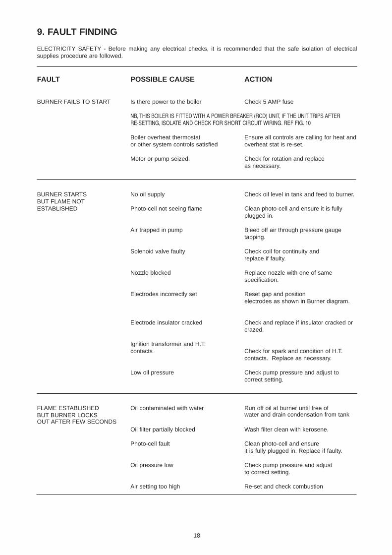
9. FAULT FINDING
ELECTRICITY SAFETY - Before making any electrical checks, it is recommended that the safe isolation of electricalsupplies procedure are followed.
FAULT POSSIBLE CAUSE ACTION
BURNER FAILS TO START Is there power to the boiler Check 5 AMP fuse
NB, THIS BOILER IS FITTED WITH A POWER BREAKER (RCD) UNIT, IF THE UNIT TRIPS AFTERRE-SETTING, ISOLATE AND CHECK FOR SHORT CIRCUIT WIRING. REF FIG. 10
Boiler overheat thermostat Ensure all controls are calling for heat andor other system controls satisfied overheat stat is re-set.
Motor or pump seized. Check for rotation and replaceas necessary.
BURNER STARTS No oil supply Check oil level in tank and feed to burner.BUT FLAME NOTESTABLISHED Photo-cell not seeing flame Clean photo-cell and ensure it is fully
plugged in.
Air trapped in pump Bleed off air through pressure gauge tapping.
Solenoid valve faulty Check coil for continuity andreplace if faulty.
Nozzle blocked Replace nozzle with one of same specification.
Electrodes incorrectly set Reset gap and position electrodes as shown in Burner diagram.
Electrode insulator cracked Check and replace if insulator cracked or crazed.
Ignition transformer and H.T. contacts Check for spark and condition of H.T.
contacts. Replace as necessary.
Low oil pressure Check pump pressure and adjust to correct setting.
FLAME ESTABLISHED Oil contaminated with water Run off oil at burner until free of BUT BURNER LOCKS water and drain condensation from tankOUT AFTER FEW SECONDS
Oil filter partially blocked Wash filter clean with kerosene.
Photo-cell fault Clean photo-cell and ensure it is fully plugged in. Replace if faulty.
Oil pressure low Check pump pressure and adjustto correct setting.
Air setting too high Re-set and check combustion
18

FAULT FINDING (Cont’d)
FAULT POSSIBLE CAUSE ACTION
POOR FLAME CUT-OFF Air in pump or at back of nozzle Bleed pump through pressure gauge port, also check for leaks in oil line if 2-pipe system.
Oil contaminated with water Run off oil at burner until free of water and drain condensation from tank.
Dirt in solenoid valve Clean or replace valve.
Pump shut-off piston sticking Replace pump.
MORNING START LOCK-OUT Faulty non-return valve or air leak Replace non-return valve and cure leak.in two pipe system
Low voltage Check with local Electricity Board.
Combustion readings incorrect Check combustion under normal running conditions and compare readings with those given under ‘Burner Settings’.
Oil level in tank falling below burner Raise tank or fit a 2-pipe system.
DELAYED IGNITION - Nozzle partially blocked Replace nozzleBURNER PULSATES ONSTART UP Oil pressure too low Check and recommission
Air setting too high Re-set and check combustion
Flue blocked or damaged Check and rectify
Fan slipping on shaft Check and retighten
Pump coupling loose or worn Check and replace
BURNER STARTS Delayed ignition Check electrode setting and adjust toVIOLENTLY correct gap
Check electrodes for damage
Check H.T. leads for damage andpositive connection
19

Item Description No. Off Part No.
1 Boiler Body WV - Painted - 65,000 1 2096102 Top Front & Bottom Insulation 1 2096953 Door Casing Assembly 1 2223614 Boiler Casing Assembly 1 2223665 Boiler Mounting Plate Assembly 1 2097106 Inner Duct Assembly 1 2097017 Fascia Panel Assembly 1 2223638 Acoustic Cassette Assembly 1 2096309 Power Breaker (RCD) 1 22159810 RCD Mounting Bracket 1 22159711 65,000 Burner Assembly 1 22342412 65,000 Bottom Plate Baffle 1 20964513 Outer Door Casing Painted 1 22172914 Grommet - Black 4 9525015 No 6x25 Flange HD Pozi sts screws 4 916131617 No 12 Woodscrew 11 9143718 Extension duct, Painted 1 20970419 Outer Sleeve 1 20970220 No 12x50 Rawlplug 11 9973721 Limit Thermostat - Yellow 1 20689222 Boiler Thermostat - Green 1 20689623 Frost Thermostat 1 20973524 Red - Neon Light 1 9645525 Green - Neon Light 1 9645726 3 Posn Switch 1 50532627 Control Panel Front 1 20968028 Control Panel Rear - Complete Assembly 1 20972929 Wiring harness - Rear 1 20974130 Wiring Harness - Front 1 20974031 Burner Plate Socket 1 20973332 Grovit (Strain Relief Bush) 5 9322933 M5x10 Pan HD Pozi Setscrew 2 9118434 Thermostat Knob 1 20689735 Flue Silencer Assembly 1 2097503637 Terminal Sealing Gasket 1 2097583839 M5x10 Pan HD Pozi Setscrew 4 91184
10 SPARES
20
FIG. 116 5 1 2 3
7

FIG. 12
FIG. 13
21
FIG. 14
13 14 15
8
810
11
12
17 18 19 20
23 26 31 33 32
21 30 29
32 28
27 34 24 25 22
35
36
3739

22
ADDITIONAL BRACKET FITTING INSTRUCTIONS
Additional bracket for fixing mountingplate to wall is required, should the cut-out have been made too large.2 off/per
See drawing 209717(contained in screw pack)
91437 No 12 X 50 SCREW(contained in screw pack)

23
DECOR PANEL FITTING INSTRUCTIONS(this item is available as an optional extra)
1. To fit decor panel to existing cupboard door firstlyremove boiler door casing as this is not required.
2. Cut away boiler insulation as shown in Fig 1, onlyremove hatched area.
3. Tape raw edges of insulation to boiler face using tapeprovided.
4. Fit insulation supplied to hatched area.
5. Fit decor panel to rear of cupboard ensuring the ballstuds are at the bottom.
6. When fitting the decor panel between units ‘X’ and ‘Y’dimensions need to be taken into account to determinethe position of the decor panel on the rear of the cup-board door. (See Fig 1).The decor panel is always fitted flush with the top edge
of the cupboard door if the boiler is fitted flush with thetop of the cupboards.If the boiler is lower than the level of the cupboardsthen it will be necessary to measure from the top of theboiler to the top of the cupboard and offset the decorpanel on the cupboard door by the measurement taken.
NOTE:THE DECOR PANEL CAN BE FITTED DIRECTLY TOTHE BOILER FOR PEOPLE WHO REQUIRE THECUPBOARD DOOR TO REMAIN HINGED. TO DOTHIS THEN FOLLOW STEPS 1 TO 4 AND THEN FITDECOR PANEL IN THE SAME WAY AS THE BOILERDOOR CASING.
To order a decor panel kit quote Part No 209790.
Fig 1

FUNCTIONAL FLOW DIAGRAM
GREEN LIGHT MAINS ON
BOILER THERMOSTAT
LIMITTHERMOSTAT
BURNER
SERVICE SWITCH
CENTRE OFFRUN PROG
N
24
EXTERNALCONTROLS
RCDTRIP
FUSED SPUR5 AMP
FROSTTHERMOSTAT
•• •

Printed by WFO Press Ltd. (01709) 740078 June 2005 Item No. 209787 Issue No. 2
TRIANCO LIMITEDThorncliffe, Chapeltown, Sheffield S35 2PH
Tel: Sheffield (0114) 257 2300
Fax: (0114) 245 1419
www.trianco.co.uk
© Trianco Limited, Copyright in this brochure and the drawings or illustrations contained in it is vested in Trianco Limited and neitherthe brochure or any part thereof may be reproduced without prior written consent.
Trianco Limited’s policy is one of continuous research and development. This may necessitate alterations to this specification.
By appointment to H.M. Queen ElizabethThe Queen Mother
Manufacturers of Domestic Boilers