exercise 2: 0l[hu dqg 5) 3rzhu $psol¿hu - lab-volt · student manual facet by lab-volt 211 analog...
TRANSCRIPT

Student Manual
210 FACET by Lab-Volt
SSB Transmission Analog Communications
Exercise 2:
EXERCISE OBJECTIVE
When you have completed this exercise, you will be able to describe the operation of a balanced mixer,
and understand the advantages of SSB transmission. You will use an oscilloscope to make signal
measurements.
DISCUSSION
The second section of the SSB transmitter frequency-translates the 455 kHz SSB to a 1000 kHz SSB and
then increases the power of that signal before the antenna transmits the signal.
The process of increasing the frequency of the 455 kHz SSB to a higher frequency for transmission is an
up-conversion.
The mixer, which is a balanced modulator, performs the up-conversion.
The mixer combines the 455 kHz SSB signal with a 1455 kHz VCO-HI signal from an oscillator to produce
a 1000 kHz SSB.
How do you suppress the 1455 kHz VCO-HI frequency in the output of the mixer?
a. by adjusting the null potentiometer until the output signal at pin 6 becomes a DSB
b.

Student Manual
FACET by Lab-Volt 211
Analog Communications SSB Transmission
An LC network that is tuned for 1000 kHz connects to the mixer’s pin 12.
frequencies.
With the 455 kHz SSB message and 1455 kHz VCO-HI inputs to the balanced mixer, the LC network
a. the 1000 kHz (difference) frequency
b. the 455 kHz (input) and 1910 kHz (sum) frequencies
SSB signal radiated by the antenna (R5).
transmission.
Student Manual
212 FACET by Lab-Volt
SSB Transmission Analog Communications
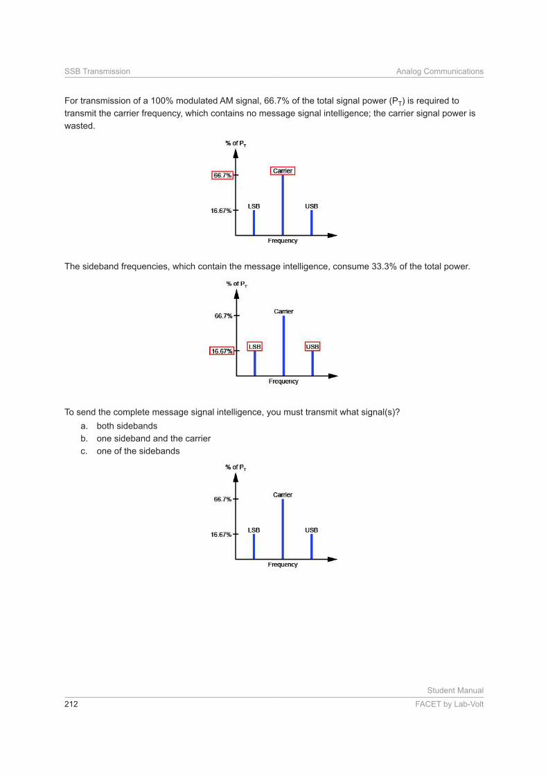
For transmission of a 100% modulated AM signal, 66.7% of the total signal power (PT) is required to
transmit the carrier frequency, which contains no message signal intelligence; the carrier signal power is
wasted.
The sideband frequencies, which contain the message intelligence, consume 33.3% of the total power.
To send the complete message signal intelligence, you must transmit what signal(s)?
a. both sidebands
b. one sideband and the carrier
c. one of the sidebands

Student Manual
FACET by Lab-Volt 213
Analog Communications SSB Transmission
Removing the carrier frequency and one of the sideband frequencies from a 100% modulated signal
conserves what percentage of the total power (PT) of a 100% modulated AM signal?
% of PT = percent (Recall Value 1)
An SSB signal’s bandwidth is no more than 50% of an AM signal or a DSB signal.
These smaller transmission bandwidths are a big advantage because the radio frequency spectrum
(airwaves) is becoming more congested every day.
Advantages of SSB Transmission Over AM Transmission:
• Only 16.67% of the total 100% modulated AM signal power is required because the carrier and one of
the sidebands are not present.
• The SSB bandwidth is less than half the AM bandwidth.
Disadvantages of SSB Transmission Over AM Transmission:
• Because more electronic components are required, cost increases and reliability may decrease.
PROCEDURE
The following procedure is divided into three sections.
• Adjust the Circuit for a 455 kHz SSB to the Mixer
• Mixer: Convert the 455 kHz SSB to a 1000 kHz SSB
•
Each section starts with an explanation of the signals that you will observe and the parameters that you
will measure and calculate.

Student Manual
214 FACET by Lab-Volt
SSB Transmission Analog Communications
Adjust the Circuit for a 455 kHz SSB to the Mixer
In this PROCEDURE section, you will adjust the balanced modulator for a 455 kHz SSB signal to the
mixer.
If you must restart this section at a later time, setup the circuit by completing the steps in the Adjust
Transmitter Circuit for a 455 kHz SSB to Mixer section in the Resources of this manual. Circuit setup
guides and the switch function guide are also located in the Resources.
When S1 is on, the modulator is automatically balanced to output a DSB signal; the null potentiometer is
disconnected from the modulator circuit.
You will adjust the carrier signal frequency for 452 kHz to obtain an SSB to the mixer.
connect the circuit shown. Be sure to place a two-post connector in the 452 kHz position on
the VCO-LO circuit block. The LSB FILTER connects to the MODULATOR with another two-
post connector.
Connect the oscilloscope channel 1 probe to the MODULATOR’s M input. While observing
the signal on channel 1, adjust the signal generator for a 300 mVpk-pk, 3 kHz sine wave
(message signal) at M.

Student Manual
FACET by Lab-Volt 215
Analog Communications SSB Transmission
Turn the NEGATIVE SUPPLY knob on the left side of the base unit fully CCW to set the
VCO-LO frequency less than 452 kHz.
Connect the channel 2 probe to the MODULATOR’s C input.
While observing the signal on channel 2, adjust the amplitude knob on VCO-LO for a
100 mVpk-pk carrier signal at C.

Student Manual
216 FACET by Lab-Volt
SSB Transmission Analog Communications
Set switch S1 to ON to automatically output a DSB from the MODULATOR.
Set S2 and S3 to OFF.
Connect the channel 2 probe to the M input of the MIXER.

Student Manual
FACET by Lab-Volt 217
Analog Communications SSB Transmission
A trace appears at the LSB FILTER output on channel 2 (display A).
Slowly increase the VCO-LO’s frequency to the MODULATOR by turning the NEGATIVE
SUPPLY knob CW until the LSB FILTER’s output amplitude is maximum (display B). This output
is an SSB signal.
Mixer: Convert the 455 kHz SSB to a 1000 kHz SSB
In this PROCEDURE section, you will balance the mixer for a DSB signal at pin 6 and an SSB signal at
pin 12.
If you are not proceeding directly from the Adjust the Circuit for a 455 kHz SSB to the Mixer portion of this
procedure or if you must restart this section at a later time, setup the circuit by completing the steps in
the Adjust Transmitter Circuit for a 455 kHz SSB to Mixer section in the Resources of this manual. Circuit
setup guides and the switch function guide are also located in the Resources.
The inputs to the mixer are the 455 kHz SSB from the LSB FILTER and a 1455 kHz signal from VCO-HI.

Student Manual
218 FACET by Lab-Volt
SSB Transmission Analog Communications
The MIXER is a balanced modulator that frequency-translates the 455 kHz SSB input to a 1000 kHz SSB
There are two mixer output terminals. Output pin 12 (the negative [ ] output) connects to the RF power
Output pin 6 (the positive [+] output) connects to VCC through a resistor.
signal at pin 6.

Student Manual
FACET by Lab-Volt 219
Analog Communications SSB Transmission
Is the 1000 kHz SSB signal at pin 12 the mixer’s difference frequency or sum frequency?
a. difference
b. sum
Connect the output of the VCO-HI circuit block to input C of the MIXER.
Set S1 to ON to automatically output a DSB from the MODULATOR.
Set S2 and S3 to OFF.

Student Manual
220 FACET by Lab-Volt
SSB Transmission Analog Communications
Connect the channel 2 probe to the MIXER’s C input. Adjust the VCO-HI signal to
100 mVpk-pk with the VCO-HI potentiometer knob.
Set the VCO-HI frequency to approximately 1455 kHz by adjusting the POSITIVE SUPPLY
knob on the base unit.

Student Manual
FACET by Lab-Volt 221
Analog Communications SSB Transmission
Connect channel 2 to the MIXER’s pin 6 output. Adjust the MIXER’s potentiometer knob for
a DSB signal at pin 6. The DSB waveform at pin 6 is shown below.
Connect channel 2 to the MIXER’s pin 12 output. Fine tune the 1455 kHz VCO-HI frequency
by adjusting the POSITIVE SUPPLY knob on the base unit for the maximum SSB signal at
pin 12. The SSB waveform at pin 12 is shown below.

Student Manual
222 FACET by Lab-Volt
SSB Transmission Analog Communications
Trigger on channel 2. Set the oscilloscope sweep to 0.5
appear as shown. If it does not, slightly adjust the MIXER’s potentiometer knob so that the
signal appears as shown.
Measure the period (T) between peaks of the waveform. Each horizontal division is 0.5 s.
T = s (Recall Value 1)
From the period (T), calculate the frequency of the SSB at pin 12 of the MIXER.
T = s (Step 9, Recall Value 1)
kHz (Recall Value 2)

Student Manual
FACET by Lab-Volt 223
Analog Communications SSB Transmission
While observing the 1000 kHz SSB signal at the MIXER’s pin 12, vary the amplitude of the 3
kHz message signal to the MODULATOR by varying the AF LEVEL knob on the SIGNAL
GENERATOR. Does the amplitude of the 1000 kHz signal at pin 12 vary with the changing
amplitude of the 3 kHz message signal?
a. yes
b. no
Connect the channel 2 probe to M of the MODULATOR, and adjust the SIGNAL
GENERATOR for a 300 mVpk-pk, 3 kHz message signal (the original setting).
input and output voltages, calculate the power gain, and compare the SSB signal power and bandwidth to
the power and bandwidth of a 100% modulated AM signal.
If you are not proceeding directly from the Adjust the Circuit for a 455 kHz SSB to the Mixer or Mixer:
Convert the 455 kHz SSB to 1000 kHz SSB portions of this procedure, or if you must restart this section
at a later time, setup the circuit by completing the steps in the Adjust Transmitter Circuit for a 455 kHz
SSB to Mixer and Adjust Transmitter Circuit for a 1000 kHz SSB from Mixer sections in the Resources of
this manual. Circuit setup guides and the switch function guide are also located in the Resources.
used for AM transmission.
When S3 is on, the antenna matching network impedance is automatically set for 330 .

Student Manual
224 FACET by Lab-Volt
SSB Transmission Analog Communications
Pi = Vi x Ii.
The output power at the antenna matching circuit equals the R5 rms voltage squared, divided by the R5
resistance: PO = VO2 .
When your measured peak-to-peak voltages are recalled, they will automatically be converted to rms
voltages for current and power calculations.
In a 100% modulated AM signal, each sideband contains 16.67% of the total signal power (PT); the
sideband power is 50% of the carrier power.
The carrier contains 66.7% of PT.
If the total power of a 100% modulated AM signal is 100 W, what is the power of the USB signal portion
(PUSB)?
PUSB = W (Recall Value 1)

Student Manual
FACET by Lab-Volt 225
Analog Communications SSB Transmission
The bandwidth of an SSB is the difference between the highest and lowest frequencies in the message
signal.
The bandwidth of an AM signal is two times the highest frequency in the message signal; the SSB
bandwidth is either half or less than half of the AM signal bandwidth.
For example, if the message signal was between 0.3 kHz and 5 kHz, the AM signal bandwidth would be
10 kHz (2 x 5 kHz). What would be the SSB bandwidth?
B = kHz (Recall Value 2)
With two-post connectors, connect the RF POWER AMPLIFIER to the MIXER and the
ANTENNA MATCHING NETWORK.
Set S1, S2, and S3 to ON.
When S1 and S2 are on, they automatically balance the MODULATOR and MIXER, respectively,
for DSB signals. When S3 is on, the ANTENNA MATCHING NETWORK impedance is
automatically set to 330 .

Student Manual
226 FACET by Lab-Volt
SSB Transmission Analog Communications
Connect the channel 1 probe to the input of the RF POWER AMPLIFIER. Measure the peak-
to-peak voltage (Vi).
Vi = mVpk-pk (Recall Value 3)
With the existing circuit conditions, the input current (Ii) to the RF POWER AMPLIFIER is
about 26 Arms. Convert the Vi value to rms voltage and use it to calculate the input power.
Vi = [(Step 3, Recall Value 3 rms
Pi = Vi x Ii
Pi = W (Recall Value 4)

Student Manual
FACET by Lab-Volt 227
Analog Communications SSB Transmission
Connect the channel 2 probe to the output of the ANTENNA MATCHING NETWORK.
Measure the peak-to-peak output voltage across R5 (VO). This resistor simulates the
impedance of the transmitting antenna.
VO = mVpk-pk (Recall Value 5)
VO = [(Step 5, Recall Value 5 rms
R5 = 51
Calculate the rms power dissipated by R5 (PO).
PO = VO2 = W (Recall Value 6)
Calculate the power gain (Ap) across the RF POWER AMPLIFIER and the ANTENNA
MATCHING NETWORK (Pi = W [Step 4, Recall Value 4] and PO = W
[Step 6, Recall Value 6]).
Ap = PO i
= (Recall Value 7)

Student Manual
228 FACET by Lab-Volt
SSB Transmission Analog Communications
In a 100% modulated AM signal, the USB accounts for 16.67% of the total signal power.
If the SSB power (PO = W [Step 6, Recall Value 6]) that you measured across R5 was
part of the 100% modulated AM signal’s power, what is the total signal power (PT) of the 100%
modulated AM signal?
PT = PO
= W (Recall Value 8)
If you were using a message signal that contained frequencies from 1 kHz to 3 kHz, the SSB
signal would have a 2 kHz bandwidth (from 1001 kHz to 1003 kHz).
What is the bandwidth (B) of a 100% modulated signal containing a message signal with
frequencies between 1 kHz and 3 kHz?
B = kHz (Recall Value 9)
CONCLUSION
• A mixer, which is a balanced modulator on your circuit board, up-converts the 455 kHz SSB to a 1000
kHz SSB.
•
•
the 1000 kHz SSB before transmission by the antenna.
• An SSB signal requires only 16.67% of the total power required for a 100% modulated AM signal.
• The bandwidth of an SSB is either half or less than half the bandwidth of an AM signal.

Student Manual
FACET by Lab-Volt 229
Analog Communications SSB Transmission
REVIEW QUESTIONS
1. Why does the mixer on your circuit board have to be a balanced modulator to convert the 455 kHz
SSB to a 1000 kHz SSB?
a. to prevent the 1455 kHz VCO-HI signal from being suppressed in the output signal
b. because the mixer output signal has to be 100% modulated
c. because it is necessary to suppress the 1455 kHz VCO-HI signal with the balanced modulator’s
null potentiometer circuit
d. to prevent a DSB signal at the output
2.
3000 kHz, what is the VCO-HI signal’s frequency to the mixer?
a. 2400 kHz
b. 3455 kHz
c. 3000 kHz
d. 2255 kHz
3.
a.
b. to provide a low antenna impedance, which is necessary for radiating the SSB signal
c.
d.

Student Manual
230 FACET by Lab-Volt
SSB Transmission Analog Communications
4. An SSB contains what percentage of the total power of a 100% modulated AM signal?
a. 66.7%
b. 33.3%
c. 16.67%
d. 25.0%
5. If the LC circuit shown is tuned for 5000 kHz and has a bandwidth of 4 kHz, what is the frequency
a. 5002 kHz to 5004 kHz
b. 4998 kHz to 5002 kHz
c. 4996 kHz to 5004 kHz
d. 4996 kHz to 4998 kHz