tracker system specification - university of wisconsin ... · tracker system specification...
TRANSCRIPT

Tracker System Specification
SALT-1510AS0001Draft Page 1 of 65
APPROVAL SHEET
TITLE : TRACKER SYSTEM SPECIFICATION
DOCUMENT NUMBER : 1510AS0001 ISSUE : Draft
SYNOPSIS : This document describes the technical requirementsor the Tracker subsystem of the Southern AfricanLarge Telescope (SALT).
KEYWORDS : Tracker, Payload Alignment, Closed Loop Tracking,Open Loop Tracking
PRPEPARED BY : Leon Nel Manager: Tracker, Payload and TCS
APPROVED : Gerhard Swart SALT System Engineer
: Kobus Meiring SALT Project Manager
DATE : August 2000
This issue is only valid when the above signatures are present.

Tracker System Specification
SALT-1510AS0001Draft Page 2 of 65
ACRONYMS AND ABBREVIATIONS
mm micronarcsec Seconds of arcCCAS Centre-of-Curvature Alignment SensorCCD Charge-coupled Device (Camera)COTS Commercial off the shelfEE(50) Enclosed Energy is 50% of total energyFoV Filed-of-ViewFWHM Full Width Half MaximumHET Hobby-Eberly TelescopeHRS High-resolution SpectrographI/O Input/Output (Device)ICD Interface Control DossierIR InfraredLRS Low-resolution SpectrographMMI Man-Machine InterfaceMTBF Mean Time Between FailuresMTTR Mean Time to Repairnm nano-metreOEM Original Equipment ManufacturerPC Personal ComputerPFIS Prime Focus Imaging SpectrographPFP Prime Focus PlatformPI Principal Investigator (Astronomer)RA, DEC Right Ascension and DeclinationRMS Root Mean SquareSA SALT AstronomerSAC Spherical Aberration CorrectorSALT Southern African Large TelescopeSO SALT OperatorSW SoftwareTAC Time Assignment CommitteeTBC To Be ConfirmedTBD To Be DeterminedTCS Telescope Control SystemUPS Uninterruptible Power SupplyUV Ultraviolet (light)XL Lower X-driveXU Upper X-drive

Tracker System Specification
SALT-1510AS0001Draft Page 3 of 65
DEFINITIONS
Acquisition time This is the length of time required to put the target at adesired position (a bore-sight), within the offsetpointing requirement, from end-of-slew, until start ofthe integration
Offset accuracy This is the ability to place a given point in the sky onthe bore-sight once the telescope has acquired anobject in the FoV.
Target This is a point in the sky. If the target is not visible tothe acquisition imager, then the target is defined asan offset from a visible star that is within the focalplane field of view.
Technical Baseline This is the design baseline that is required to fulfil therequirements of the SALT Observatory ScienceRequirements, Issue 7.1, and is the topic of thisSpecification.
Tracker System Specification
SALT-1510AS0001Draft Page 4 of 65
TABLE OF CONTENTS
1 Scope.................................................................................................. 101.1 Identification........................................................................................................................101.2 System overview ...............................................................................................................10
2 Referenced documents..................................................................... 123 Customer Furnished Equipment and Responsibilities.................. 144 Functional Requirements ................................................................. 154.1 Main purpose......................................................................................................................154.2 Functional definition ..........................................................................................................164.3 Major Control Functions ...................................................................................................174.3.1 Subsystem modes, States and Events............................................................................174.3.2 Functional Flow Diagram..................................................................................................204.3.3 Function descriptions.......................................................................................................21
4.3.3.1 TCS Communication......................................................................................................214.3.3.2 Payload Computer Communication ...............................................................................224.3.3.3 Axes Controllers Communication .................................................................................224.3.3.4 Payload Alignment Communication...............................................................................224.3.3.5 Thermal Control Communication ...................................................................................234.3.3.6 Power Switches Communication .................................................................................234.3.3.7 Time Synchronization Input ..........................................................................................234.3.3.8 Tracker Algorithms.......................................................................................................23
4.3.3.8.1 Power Up..............................................................................................................234.3.3.8.2 Shut Down............................................................................................................234.3.3.8.3 Time Synchronization............................................................................................234.3.3.8.4 Tracker Mount Model.............................................................................................244.3.3.8.5 Guidance Corrections...........................................................................................244.3.3.8.6 Orthogonality Corrections.....................................................................................244.3.3.8.7 Axes Command Generator ...................................................................................244.3.3.8.8 Thermal loop..........................................................................................................244.3.3.8.9 Mode and State Control.........................................................................................244.3.3.8.10 Diagnostics & Safety............................................................................................244.3.3.8.11 Software Set up & Maintenance..........................................................................24
4.3.3.9 Tracker Man-Machine-Interface (MMI) .........................................................................254.3.3.10 Axes Control.............................................................................................................254.3.3.11 Payload Alignment Sensors......................................................................................254.3.3.12 Thermal Control.........................................................................................................254.3.3.13 Power Switches.......................................................................................................254.3.3.14 Gravity Compensation ..............................................................................................254.3.3.15 Structural Support ....................................................................................................25
4.3.4 Operational Concept ........................................................................................................25
5 Tracker Technical Requirements ..................................................... 285.1 Schematic diagram ............................................................................................................285.2 SALT Tracker Interfaces...................................................................................................285.2.1 SALT Tracker External Interfaces ...................................................................................28

Tracker System Specification
SALT-1510AS0001Draft Page 5 of 65
5.2.2 SALT Tracker Internal Interfaces.....................................................................................315.3 SALT Tracker Characteristics .........................................................................................325.3.1 Performance Characteristics...........................................................................................32
5.3.1.1 Motion Ranges..............................................................................................................335.3.1.2 Motion Symmetry..........................................................................................................335.3.1.3 Speed...........................................................................................................................345.3.1.4 Accuracy (TBC9) ........................................................................................................345.3.1.5 Thermal Control Accuracy and Heat Dumping .............................................................355.3.1.6 Control loop Requirements ...........................................................................................365.3.1.7 Safety...........................................................................................................................365.3.1.8 Structural Frequencies (TBC10)..................................................................................365.3.1.9 Static Structural Deflections (TBC11)..........................................................................375.3.1.10 Dynamic Structural Deflections ................................................................................375.3.1.11 Orthogonality of Axes : (TBC13) .............................................................................375.3.1.12 Rotation position of Payload (TBC14) ......................................................................385.3.1.13 Maximum Acceleration and Jerk...............................................................................385.3.1.14 Additional search Speeds ........................................................................................385.3.1.15 Forces in Hexapod Struts.........................................................................................385.3.1.16 Travel limits...............................................................................................................395.3.1.17 Payload Alignment ....................................................................................................395.3.1.18 Tracker MMI ..............................................................................................................39
5.3.2 Physical Characteristics ..................................................................................................395.3.2.1 Obscuration..................................................................................................................395.3.2.2 Mass.............................................................................................................................395.3.2.3 Maximum surface temperatures...................................................................................39
5.3.2.3.1 Objects in the optical path.....................................................................................395.3.2.3.2 Objects outside the optical path............................................................................40
5.3.2.4 Minimum surface temperatures....................................................................................405.3.2.4.1 Objects in the optical path.....................................................................................405.3.2.4.2 Objects outside the optical path............................................................................40
5.3.2.5 Component/module replacement ..................................................................................415.3.2.6 Payload Clearance and Envelope.................................................................................41
5.3.3 Environmental Requirements............................................................................................415.3.3.1 Normal Operational Environment ..................................................................................415.3.3.2 Marginal Operational Environment................................................................................415.3.3.3 Survival Environment....................................................................................................42
5.4 Operation and Maintenance Requirements..................................................................425.4.1 Packaging, handling, storage...........................................................................................425.4.2 Product Documentation....................................................................................................425.4.3 Personnel and Training ....................................................................................................43
5.4.3.1 Operation......................................................................................................................435.4.3.2 Maintenance.................................................................................................................43
5.4.4 Availability........................................................................................................................435.4.4.1 Science Efficiency .......................................................................................................43
5.4.4.1.1 Reliability ...............................................................................................................445.4.4.1.2 Tracker Maintainability...........................................................................................44
Tracker System Specification
SALT-1510AS0001Draft Page 6 of 65
5.4.4.2 Measures to achieve efficiency...................................................................................445.5 Design and Construction constraints............................................................................455.5.1 General design guidelines and constraints......................................................................455.5.2 Materials, Processes and Parts.......................................................................................465.5.3 Electromagnetic Radiation................................................................................................465.5.4 Workmanship ...................................................................................................................465.5.5 Interchangeability.............................................................................................................465.5.6 Safety ..............................................................................................................................47
5.5.6.1 Safety-critical failures..................................................................................................475.5.6.2 Software safety...........................................................................................................475.5.6.3 Safe initialisation...........................................................................................................475.5.6.4 Local electric operation................................................................................................47
5.5.7 Ergonomics ......................................................................................................................475.5.8 Special commissioning requirements...............................................................................47
5.5.8.1 Subsystem MMI’s..........................................................................................................475.5.8.2 Test Points....................................................................................................................485.5.8.3 Test Data......................................................................................................................485.5.8.4 Spotter Telescope........................................................................................................48
5.5.9 Software..........................................................................................................................485.5.10 Computer Hardware ........................................................................................................485.5.11 Electrical Design...............................................................................................................48
5.5.11.1 UPS...........................................................................................................................485.5.11.1.1 Installed Capacity .................................................................................................495.5.11.1.2 Use of UPS power ...............................................................................................495.5.11.1.3 General UPS Requirements..................................................................................49
5.5.11.2 Standby Power generators......................................................................................495.5.11.2.1 Use of Emergency Power....................................................................................495.5.11.2.2 General Emergency Power Requirements...........................................................49
5.5.11.3 Cable sizing ..............................................................................................................495.5.11.4 General Electrical Requirements...............................................................................50
5.5.12 Future growth..................................................................................................................505.5.12.1 Remote Observing....................................................................................................50
6 Subsystem technical requirements ................................................. 516.1 Major Component List ......................................................................................................516.2 Major Component Characteristics .................................................................................516.2.1 Tracker Computer System ...............................................................................................52
6.2.1.1 Computer Hardware:...................................................................................................526.2.1.2 Software Suite.............................................................................................................526.2.1.3 Power Switches ..........................................................................................................52
6.2.2 Beam................................................................................................................................536.2.3 Carriage ...........................................................................................................................536.2.4 Hexapod System..............................................................................................................546.2.5 Linear Drive Systems.......................................................................................................546.2.6 Rho-Drive System............................................................................................................556.2.7 Payload Alignment System...............................................................................................566.2.8 Thermal Control System...................................................................................................56

Tracker System Specification
SALT-1510AS0001Draft Page 7 of 65
6.2.9 Cable & Tube Handlers and Enclosures ..........................................................................56
7 Test Requirements ............................................................................ 567.1 Verification cross-reference Matrix...............................................................................567.2 Detailed Test Methods......................................................................................................57
8 Notes................................................................................................... 57APPENDIX A: TIMELINESAPPENDIX B: LIST OF TBC’S AND TBD’S

Tracker System Specification
SALT-1510AS0001Draft Page 8 of 65
TABLE OF FIGURES
Figure 1. SALT Subsystems................................................................................................... 10Figure 2. SALT Pier, structure, primary mirror and tracker ............................................... 11Figure 3. Facility and Dome.................................................................................................... 12Figure 4. Tracker on Top Hex................................................................................................. 16Figure 5. Tracker Coordinate System (ITF) ......................................................................... 16Figure 6. System modes......................................................................................................... 18Figure 7. Tracker Functional Flow Diagram........................................................................ 21Figure 8. Major Components of Tracker Subsystem and Communication interfaces28Figure 9. Schematic showing SALT Tracker External Interfaces .................................... 29Figure 10. Interfaces............................................................................................................... 32Figure 11. View of tracker on upper hex.............................................................................. 33Figure 12. Detail of beam...................................................................................................... 53Figure 13. Conceptual illustration of the overall Carriage............................................... 54Figure 14. Linear Dual Drive system................................................................................... 55Figure 15. Cable and Tube Handlers ................................................................................. 56

Tracker System Specification
SALT-1510AS0001Draft Page 9 of 65
LIST OF TABLES
Table 1 Description of System Modes................................................................................... 18Table 2 Description of Mode Transition Events................................................................... 19Table 3 Degrees of freedom ................................................................................................... 21Table 4 Closed loop tracking .................................................................................................. 25Table 5 Open Loop Tracking................................................................................................... 26Table 6 Positioning. .................................................................................................................. 27Table 7 Tracker external interfaces........................................................................................ 29Table 8 Tracker to Optical Payload interfaces (refer Figure 10) ....................................... 30Table 9 Internal Interfaces ....................................................................................................... 32Table 10 Coordinate system.................................................................................................. 33Table 11 Maximum errors....................................................................................................... 33Table 12 Tracker speed.......................................................................................................... 34Table 13 Tracker accuracy...................................................................................................... 34Table 14 Structural dynamics ................................................................................................ 36Table 15 Structural deflections: static .................................................................................. 37Table 16 Structural deflections: dynamic............................................................................. 37Table 17 Orthogonality of Axes : After correction by mount model.................................. 38Table 18 Orthogonality of Axes : Manufacturing.................................................................. 38Table 19 Normal Operational Environment ........................................................................ 41Table 20 Marginal Operational Environment ...................................................................... 41Table 21 SALT Survival Operating Environment................................................................. 42Table 22 : SALT Efficiency....................................................................................................... 44Table 23 Part identification..................................................................................................... 46Table 24 Tracker major components................................................................................... 51Table 25 Verification cross-reference Matrix (TBD21)....................................................... 57

Tracker System Specification
SALT-1510AS0001Draft Page 10 of 65
1 Scope
1.1 Identification
This document specifies the requirements for the Tracker system of the Southern African LargeTelescope. Where applicable, the possible growth paths for later upgrades have been identified.
In general, the word “shall” is used to indicate mandatory requirements w hile descriptive statementsare used to provide non-mandatory information
1.2 System overview
The purpose of SALT is to collect light from astronomical objects, accurately focus it onto thetelescope focal plane from where it will proceed into an optical instrument while tracking the relativemovement of the target across the sky to maximise exposure time. The SALT system comprises ofthe subsystems as depicted in Figure 1 below:
Figure 1. SALT Subsystems
This specification will focus on the Tracker as numbered 1510 in the breakdown of Figure 1.
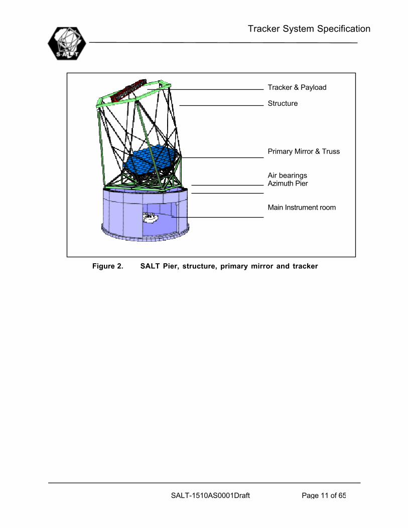
Figure 2 and Figure 3 below are schematic representations of the internal layout of the telescope, the facility and dome
1000TelescopeSystem
1100Facility
1200TelescopeStructure
1300Dome
1400Primary Mirror
1500Tracker &Payload
1600Commissioning Instrument
1700TCS
1510Tracker
1520Payload
Tracker System Specification
SALT-1510AS0001Draft Page 11 of 65
Figure 2. SALT Pier, structure, primary mirror and tracker
Tracker & Payload
Structure
Primary Mirror & Truss
Air bearingsAzimuth Pier
Main Instrument room

Tracker System Specification
SALT-1510AS0001Draft Page 12 of 65
Figure 3. Facility and Dome
2 Referenced documents
SALT DB000531 SALT Observatory Science Requirements, Issue 7.1, D.A.H. Buckley,dd. 31 May 2000
LWR95055 Hobby-Eberly Telescope Operations Requirements Document, L.W.Ramsey, dd. 27/11/95, edited by D Buckley
HET Tech Report #67 Statement of Work – HET Tracker, October 1994HET Tech Report #44 HET Error Budget, April 94
Keck Visit ReportScience with SALT, DAH Buckley, March 1998SPIE proceedings (various)
SALT-1000AS0028 Specification for the SALT Fibre-Feed System (TBC1)SALT-1000AS0029 Specification for the SALT Prime Focus Instrument (TBC1)SALT-1000AS0027 SALT External Interface Control Dossier (TBC1)SALT-1000AS0013 SALT Electrical Interface Control Dossier (TBC1)SALT-1000AS0014 SALT Physical Interface Control Dossier (TBC1)SALT-1000AA0030 SALT Safety Analysis (TBC1)SALT-1000AS0031 SALT Axes and Calibration definition (TBC1)SALT-1000AA0017 SALT Error Budget (TBC1)SALT-1000BS0021 SALT Requirements for Built-in Testing (TBC1)SALT-1000BS0010 SALT Software Standard (TBC1)SALT-1000BS0011 SALT Computer Standard (TBC1)

Tracker System Specification
SALT-1510AS0001Draft Page 13 of 65
SALT-1000AS0032 SALT Electrical Requirements (TBC1)SALT Report of Interim Project Team, April 1999
SALT-1000AS0033 SALT Support Requirements (TBC1)Applicable South African Building and Construction StandardsApplicable South African Legal Requirements (TBC1)Safety, Health and Environment Act

Tracker System Specification
SALT-1510AS0001Draft Page 14 of 65
3 Customer Furnished Equipment and Responsibilities
There shall be no customer furnished equipment in the tracker system
Tracker System Specification
SALT-1510AS0001Draft Page 15 of 65
4 Functional Requirements
4.1 Main purpose
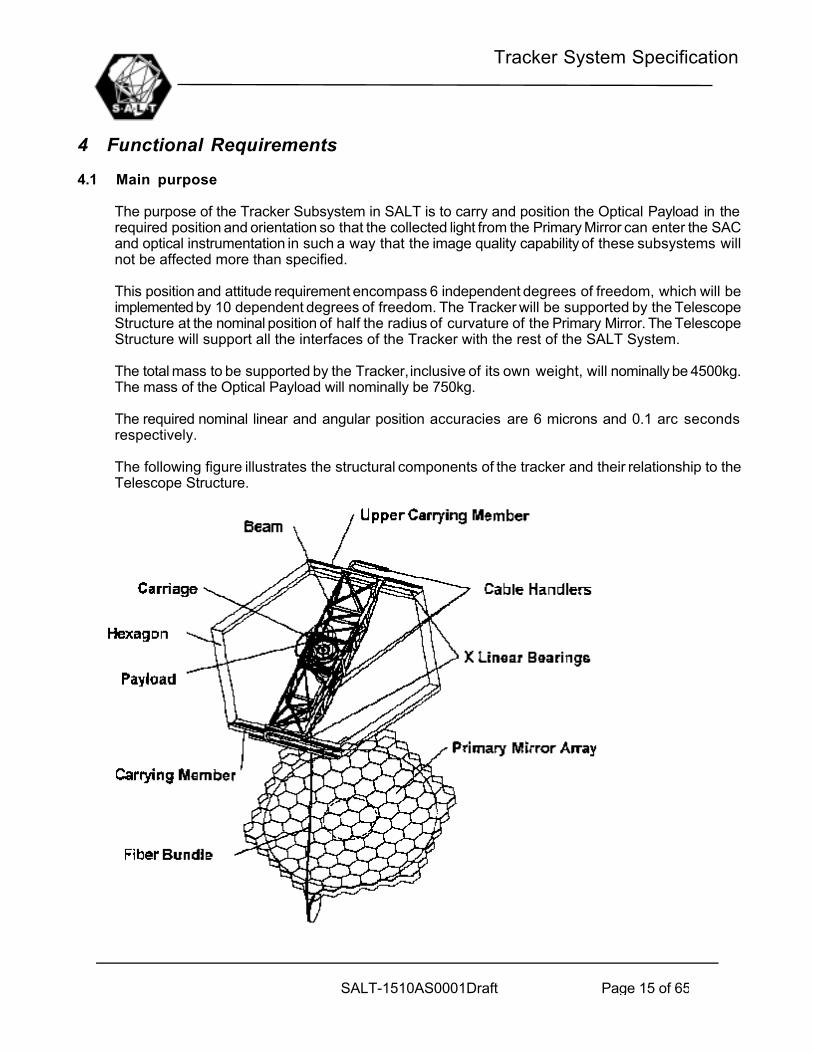
The purpose of the Tracker Subsystem in SALT is to carry and position the Optical Payload in therequired position and orientation so that the collected light from the Primary Mirror can enter the SACand optical instrumentation in such a way that the image quality capability of these subsystems willnot be affected more than specified.
This position and attitude requirement encompass 6 independent degrees of freedom, which will beimplemented by 10 dependent degrees of freedom. The Tracker will be supported by the TelescopeStructure at the nominal position of half the radius of curvature of the Primary Mirror. The TelescopeStructure will support all the interfaces of the Tracker with the rest of the SALT System.
The total mass to be supported by the Tracker, inclusive of its own weight, will nominally be 4500kg.The mass of the Optical Payload will nominally be 750kg.
The required nominal linear and angular position accuracies are 6 microns and 0.1 arc secondsrespectively.
The following figure illustrates the structural components of the tracker and their relationship to theTelescope Structure.

Tracker System Specification
SALT-1510AS0001Draft Page 16 of 65
Figure 4. Tracker on Top Hex
The coordinate system in which the tracker motions are described is called the Ideal Tracker Frame(ITF) and is defined in Figure 5 below. A detailed description of all coordinate systems is given inSALT-1000AS0031: SALT Axes and Calibration definition, listed in Section 2.
Figure 5. Tracker Coordinate System (ITF)
In operation on SALT, the Tracker will perform the following actions when commanded to a particulartarget in the sky:
a) Slew to an X,Y,Z location corresponding to the instantaneous celestial position of the targetin the focal surface
b) The payload will be positioned in q,f to align with the normal of the primary mirror at that pointc) The value of r rotation on the sky will be chosen depending wether the target is an extended
or point sourced) A computing mount model will drive all six independent axes along the desired trajectory,
correcting for inherent tracker errors(way straightness variations, Beam sag etc)e) When trajectory is complete, the tracker shall stop all motion unless a new preloaded
trajectory is available.
The Tracker subsystem will be under command from the TCS. The user interface on the TrackerComputer must be duplicated at TCS level. The user interface on both systems must at all timespresent the same information and system status.
4.2 Functional definition
The main functional objectives of the Tracker subsystem are:

Tracker System Specification
SALT-1510AS0001Draft Page 17 of 65
a) Closed Loop Tracking: Tracker position is corrected based upon the input from an opticalguide star. The different axes will be closed loop controlled based upon local sensormeasurements.
b) Open Loop Tracking: Tracker position is adjusted according to operator selected siderealrate. The different axes will be closed loop controlled based upon local sensor measurements.
c) Pointing: The tracker is positioned at any location and attitude in its travel range, as selectedby operator
The following major functions have to be performed by the Tracker Subsystem to achieve the mainfunctional objectives as stated above:
_ Communication_ with other SALT subsystems (TCS Payload Computer)_ with other Tracker subsystems (Axes Controllers, Sensors)
_ Algorithm Execution_ Mount Model (Coordinate Transformations)_ Mode and State Control_ Diagnostics & Safety etc
_ Man Machine Interface (MMI)_ Axes Control : Tracking of commands to all axes_ Payload Alignment Sensing (to maintain orthogonality to primary mirror)_ Thermal Control : Ensure that all surface temperatures and heat generation in light path are within
specification_ Gravity compensation: To alleviate the effect of gravity on drive systems_ Structural support
A detailed functional flow diagram is presented in Figure 7.
The following predefined positions shall be selectable from Manual and Automatic Modes:
PARK - at Vertex of Primary MirrorMAINTENANCE – Most accessible positionPM - ALIGN – LEFT – For Alignment of Left half of Primary MirrorPM - ALIGN – RIGHT – For Alignment of Right half of Primary MirrorDOME_CRANE – Best position to access with Dome Crane
4.3 Major Control Functions
4.3.1 Subsystem modes, States and Events
The operation of the tracker system has been divided into distinct modes. Each Mode issubdivided into a number of States. Transitions between Modes and States are triggered byEvents.
Tracker System Specification
SALT-1510AS0001Draft Page 18 of 65
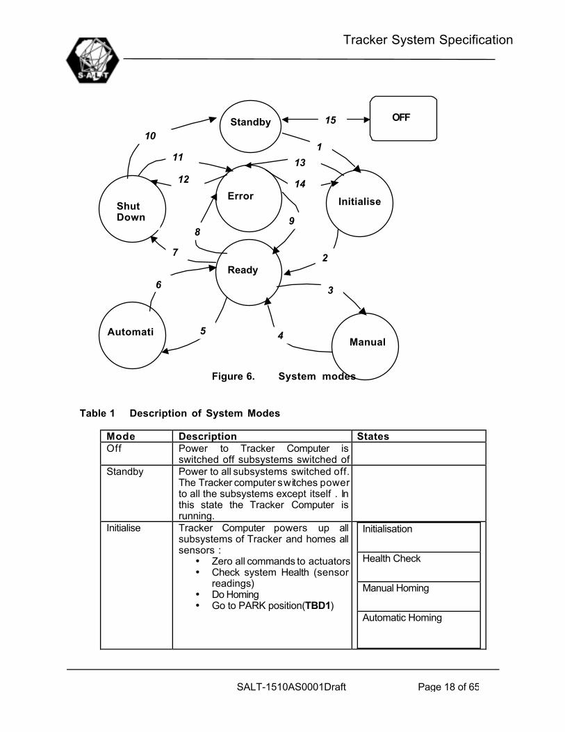
Figure 6. System modes
Table 1 Description of System Modes
Mode Description StatesOff Power to Tracker Computer is
switched off subsystems switched ofStandby Power to all subsystems switched off.
The Tracker computer switches powerto all the subsystems except itself . Inthis state the Tracker Computer isrunning.
Initialise Tracker Computer powers up allsubsystems of Tracker and homes allsensors :
• Zero all commands to actuators• Check system Health (sensor
readings)• Do Homing• Go to PARK position(TBD1)
Initialisation
Health Check
Manual Homing
Automatic Homing
1
2
3
5
6
4
7
89
10Standby
InitialiseShutDown
Error
Ready
ManualAutomatic
11
12
13
14
OFF15
Tracker System Specification
SALT-1510AS0001Draft Page 19 of 65
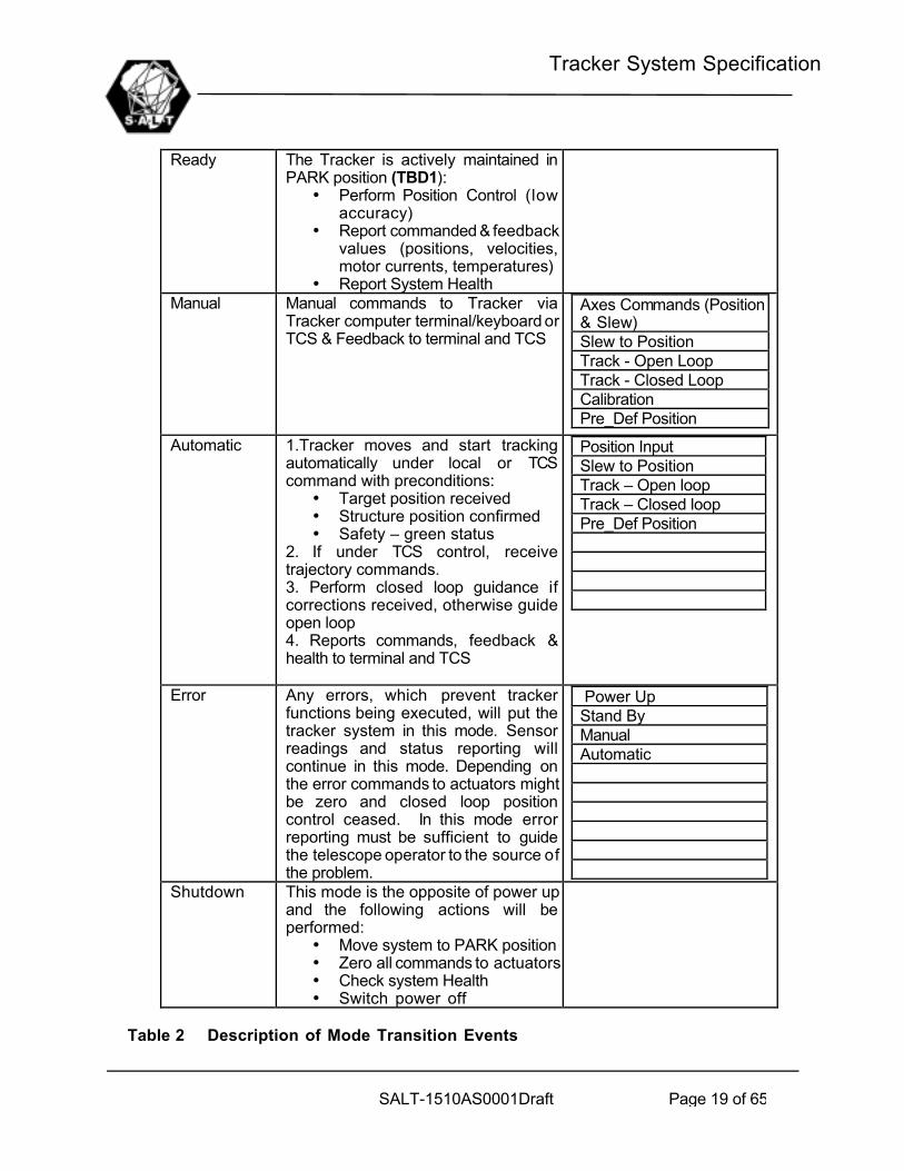
Ready The Tracker is actively maintained inPARK position (TBD1):
• Perform Position Control (lowaccuracy)
• Report commanded & feedbackvalues (positions, velocities,motor currents, temperatures)
• Report System HealthManual Manual commands to Tracker via
Tracker computer terminal/keyboard orTCS & Feedback to terminal and TCS
Axes Commands (Position& Slew)Slew to PositionTrack - Open LoopTrack - Closed LoopCalibrationPre_Def Position
Automatic 1.Tracker moves and start trackingautomatically under local or TCScommand with preconditions:
• Target position received• Structure position confirmed• Safety – green status
2. If under TCS control, receivetrajectory commands.3. Perform closed loop guidance ifcorrections received, otherwise guideopen loop4. Reports commands, feedback &health to terminal and TCS
Position InputSlew to PositionTrack – Open loopTrack – Closed loopPre_Def Position
Error Any errors, which prevent trackerfunctions being executed, will put thetracker system in this mode. Sensorreadings and status reporting willcontinue in this mode. Depending onthe error commands to actuators mightbe zero and closed loop positioncontrol ceased. In this mode errorreporting must be sufficient to guidethe telescope operator to the source ofthe problem.
Power UpStand ByManualAutomatic
Shutdown This mode is the opposite of power upand the following actions will beperformed:
• Move system to PARK position• Zero all commands to actuators• Check system Health• Switch power off
Table 2 Description of Mode Transition Events

Tracker System Specification
SALT-1510AS0001Draft Page 20 of 65
EVENT From Mode To Mode SENSOR/INPUT1 OFF INITIALISE Button – Tracker Computer2 INITIALISE READY Software Switch – On
successful power up3 READY MANUAL Button – Tracker Computer4 MANUAL READY Button – Tracker Computer
OrError Condition
5 READY AUTOMATIC Button – Tracker Computer6 AUTOMATIC READY Button – Tracker Computer
OrError Condition
7 READY SHUTDOWN Button – Tracker Computer8 READY ERROR Error Conditions9 ERROR READY Errors Cleared and if state was
entered from STANDBY10 SHUTDOWN OFF Button – Tracker Computer11 SHUTDOWN ERROR Error Conditions12 ERROR SHUTDOWN Errors Cleared and if state was
entered from SHUTDOWN orPOWER UP
13 INITIALISE ERROR Error Conditions14 ERROR INITIALISE Errors Cleared and if state was
entered from POWER UP15 OFF/STANDBY STANDBY/OFF Power Switch
4.3.2 Functional Flow Diagram
TCS
4. AXES CONTROL1.1.1.1.1.1.1 TRACKERCOMPUTE
R1. COMMS
1.1 Ethernet
1.1.1 TCS Comms
1.1.2 Payload Computer Comms
Time Sync Input
1.3 Other
1.2.1Payload AlignmentComms
1.2 RS485
1.2.2Thermal Control Comms
4.1 Axes Controllers 4.3 Sensors
4.2 Servo Amps 4.4 Motors Load
Trajectory Command GeneratorPrecision Time Sync
Tracker Temp SetpointDetermination
Tracker Computer Comms
PAYLOAD COMPUTER
Tracker Computer Comms
4.5 Brakes
TRACKER

Tracker System Specification
SALT-1510AS0001Draft Page 21 of 65
Figure 7. Tracker Functional Flow Diagram
4.3.3 Function descriptions
All the functions identified in Figure 7 are discussed below. The relationship between thedependent and independent degrees of freedom (D.O.F.) are as follows:
Table 3 Degrees of freedomINDEPENDENT D.O.F. DEPENDENT D.O.F.X XL, XU (upper and lower x) –drivesY Y – driveZ H1 to H6 (hexapod legs),q H1 to H6 (hexapod legs)f H1 to H6 (hexapod legs)r Rho stage
4.3.3.1 TCS COMMUNICATION
The TCS shall send the following commands to the tracker computer:• Request Tracker Computer MMI and Data (full control at TCS level – Operating
System Function)• Mode & State Commands
6. THERMAL CONTROL
5. Payload ALIGNMENTSENSORS
1.1.3 Axes Controllers Comms 1.2.3Power Switches Comms
6.1Analog Output
6.2 Analog Input
6.4 Valves
6.3 Temp Sensors
7. POWER SWITCHES
7.1 Digital Output 7.2 Relays
2.TRACKER ALGORITHMS
3. TRACKER MMI
2.1Power Up
2.2Shutdown
2.3Time Synchronization
2.4Tracker Mount Model
2.5Guidance Corrections
2.7Orthogonality Corrections
2.6Axes Command Generator
2.8Thermal Loop
2.9Mode & State Control
2.10Diagnostics & Safety
2.11Software Setup & maint
8. GRAVITY COMPENSATION
8.1 Analog Output
8.2 Analog Input 8.3 Pressure Sensors
8.4 Valves
1.2.4Gravity Comp Comms
9. Structural Support

Tracker System Specification
SALT-1510AS0001Draft Page 22 of 65
• Trajectory Commands (t,x,y,z,q,f,r) every 30 seconds with 100ms time-steps(TBC2). These commands are in the IDEAL TRACKER FRAME(ITF)
• Acquisition Offset Command (t,dx,dy) at 10Hz• Thermal Control Set points at 0.01Hz• Safety Commands (Emergency Stop etc) at 10 Hz (TBC3)
The Tracker Computer shall send the following information back to TCS:• MMI Screens (TCS will have access to Tracker computer MMI with full
functionality of MMI – Operating System Function)• Current Mode & State at 10Hz• Calculated Trajectory position (t,x,y,z,q,f,r) in ITF at 10Hz• Temperature measurements for set points at 1Hz• Payload Alignment Sensor Measurements (t, q,f,range) in ITF at 10Hz• Diagnostics and Safety Status (TBD3)• Individual Actuator positions, time stamped (x10)
4.3.3.2 PAYLOAD COMPUTER COMMUNICATION
The Tracker Computer/TCS (TBD4) shall send the following commands to the payloadcomputer:_ Moving Baffle position commands_ Guidance probe position commands_ ADC rotation command
The Payload Computer shall send the following information to the Tracker Computer:• Guidance Errors (t,dx,dy) in ITF at a frequency of 1Hz (TBC4) .
4.3.3.3 AXES CONTROLLERS COMMUNICATION
The Tracker Computer shall send the following information to the Axes Controllers:• Axes Commands(t,XL,XU,Y,h1,h2,h3,h4,h5,h6, r) at frequency of 10Hz
TBC5 .
• Mode Commands (Slew / track /emergency stop) at 10 Hz• Predefined Positions and Commands whenever required
The Axes Controllers shall send the following information to the Tracker Computer:• Sensor Measurements (t,XL,XU,Y,h1,h2,h3,h4,h5,h6, r,skewing) at 10Hz• Current Modes at 10Hz• Calculated Position Errors(t,XL,XU,Y,h1,h2,h3,h4,h5,h6, r,skewing) at 10Hz• Measured Motor Currents at 10Hz
4.3.3.4 PAYLOAD ALIGNMENT COMMUNICATION
The Tracker Computer shall send the following information to the Payload AlignmentSensors

Tracker System Specification
SALT-1510AS0001Draft Page 23 of 65
_ Commands for set up / calibration (Fixed set of commands asavailable)
The Payload Alignment Sensors shall send the following information to the TrackerComputer:
_ Sensor Measurements (t, q,f,range) (TBC6) at 10Hz
4.3.3.5 THERMAL CONTROL COMMUNICATION
The Tracker Computer shall send the following information to the Thermal Control AnalogueOutput
• Commands for Valves (xn) at 0.01Hz (TBD2)
The Thermal Control Analogue Output shall send the following information to the TrackerComputer:
• Temperature Measurements (xm) at 0.1Hz (TBD2)
4.3.3.6 POWER SWITCHES COMMUNICATION
The Tracker Computer shall send the following information to the Power Switches DigitalOutput
_ On/Off Commands for Switches [Axes Controller(x10),PayloadAlignment Sensors(x1),Thermal Control(x1), GravityCompensation(x1)] (TBC7)
4.3.3.7 TIME SYNCHRONIZATION INPUT
The TCS and Tracker Computer shall be time synchronized to an accuracy of 10ms (TBC8)
4.3.3.8 TRACKER ALGORITHMS
The execution of all Tracker Computer functions should be sufficiently fast as to ensure acycle time of 100ms or less.
4.3.3.8.1 Power Up
The Tracker System shall be powered up and sensors homed in a controlled fashion
4.3.3.8.2 Shut Down
The Tracker System shall be parked and shut down in a controlled fashion
4.3.3.8.3 Time Synchronization
The Tracker Computer local time shall be synchronised with the TCS computer as specifiedin 3.1.2.7.

Tracker System Specification
SALT-1510AS0001Draft Page 24 of 65
4.3.3.8.4 Tracker Mount Model
This model defines :• a conversion to convert from the TCS commands (t,x,y,z,q,f,r) to a
Tracker equivalent set (t,xe,ye,ze,q e,fe,re), both in ITF.• A conversion to convert to Hexapod Frame(HPF)• Defines calibration factors and coefficients• Rotation point of Payload• Correction table for decenters,tip & tilt mounting of payload as a function
of rho
These conversion takes into account the orthogonality of the various trackeraxes, structural deflections and sensor mounting errors
4.3.3.8.5 Guidance Corrections
A set of guidance errors (t,xguid,yguid,zguid,q guid,fguid,rguid), in ITF, is calculated from theguidance input (t,dx,dy).
4.3.3.8.6 Orthogonality Corrections
A set of of Payload position errors(t,xguid,yguid,zguid,q guid,fguid,rguid), in ITF, is calculated fromthe input(t, ,q ,f,range).
4.3.3.8.7 Axes Command Generator
Using the results from above the commands to XL, XU, Y, H1, H2, H3, H4, H5, H6, r arecalculated. The feedback from the axes controllers is used to calculate the measuredposition in ITF(t,xm,ym,ze,q m,fm,rm) .
4.3.3.8.8 Thermal loop
Close the thermal control loops to ensure temperature errors of less than 1 degreeC.(TBD2)
4.3.3.8.9 Mode and State Control
Control the modes and states of the Tracker sub system.
4.3.3.8.10 Diagnostics & Safety
Performs all diagnostics and safety functions. (TBD3)
4.3.3.8.11 Software Set up & Maintenance
Performs all set up and maintenance functions:• Log real time data to disk for analysis• Save/retrieve Calibration Data• Save/retrieve software set up

Tracker System Specification
SALT-1510AS0001Draft Page 25 of 65
4.3.3.9 TRACKER MAN-MACHINE-INTERFACE (MMI)
Implements the MMI (TBD5).
4.3.3.10 AXES CONTROL
Implements the mode commands and track the position commands. The X and Y Drivesshall be dual drives, one for slewing and one for tracking. Skewing of the X-Drives shall becontrolled actively. Axes control shall satisfy the requirements in paragraph 5.3.1.
4.3.3.11 PAYLOAD ALIGNMENT SENSORS
The attitude and position of the payload relative to the primary mirror shall be measured inreal time to satisfy the requirements in paragraph 5.3.1.
4.3.3.12 THERMAL CONTROL
This function implements the valve commands from the Tracker computer and reads thetemperature sensors. The combined thermal control and thermal loop functions shall satisfythe performance requirements in paragraph 5.3.1.
4.3.3.13 POWER SWITCHES
This function implements the relay commands from the Tracker computer. This functionshall satisfy the performance requirement in paragraph 5.3.1.
4.3.3.14 GRAVITY COMPENSATION
This function implements the relay commands from the Tracker computer. This functionshall satisfy the performance requirement in paragraph 5.3.1.
4.3.3.15 STRUCTURAL SUPPORT
The tracker subsystem shall provide sufficient structural support to carry all the relevanttracker components and Optical Payload at the primary mirror focal surface. This structurewill be supported by the top hex of the telescope structure. This support shall satisfy theperformance requirements in paragraph 5.3.1.
4.3.4 Operational Concept
Closed and open loop tracking, and pointing, will be executed as follows:
Table 4 Closed loop trackingNo Action Start Time Frequency Remarks1. Star position input by SA, SO
single position or scheduledpositions – on TCS terminal
Acquisition time– 3 minutesminimum
Once per target Star position:RA,DEC,EpochTime

Tracker System Specification
SALT-1510AS0001Draft Page 26 of 65
2. Acquisition and Tracking starttimes and ObservationDuration for each target –input by SA on TCS terminal
Acquisition time– 3 minutesminimum
Once per target Time availablebetweenAcquisition andTrack must bevariable by RA
3. TCS send Acquisition andtracking start times andposition to Tracker computer
Acquisition time– 2.5 minutesminimum
Once per target
4. Tracker and Payload slewedto position in 3
Immediately after3.
5. Tracker computer reports toTCS when in position
Acquisition Time– 30 seconds
Once per target
6. TCS send trajectorycommands(x,y,z,q,f,r) toTracker Computer
Immediately after5.
Once every 30sec
Open loopcommands
7. Tracker executes commandsin 6.
According totime stamp ofcommands
Continuously (atsamplingfrequency of axes controllers)
Controllersshouldinterpolatecommandsbetweentrajectory points
8. Target and Guid Starsselected by SA – on TCSterminal
Any timebetweenAcquisition andtrack start time
Once per target
9 Payload Computer sendscorrection signals to Trackercomputer (x,y corrections)
When locked onguid star/s
1Hz
10. Beyond track start time –closed loop tracking, if nocorrection signals frompayload – open loop tracking
Start of Track Continuously (atsamplingfrequency of axes controllers)
Controllersshouldinterpolatecommands
Table 5 Open Loop Tracking.
No Action Start Time Frequency Remarks1. Star position input by SA,SO
single position or scheduledpositions – on TCS terminal
Acquisition time– 3 minutesminimum
Once per target Star position:RA,DEC,EpochTime
2. Sidereal Rate selected bySA,SO
Acquisition time– 3 minutesminimum
Any time RA can adjustsidereal rate
3. Acquisition and Tracking starttimes and ObservationDuration for each target –input by SA on TCS terminal
Acquisition time– 3 minutesminimum
Once per target Time availablebetweenAcquisition andTrack must bevariable by RA
4. TCS send Acquisition andtracking start times andposition to Tracker computer
Acquisition time– 2.5 minutesminimum
Once per target

Tracker System Specification
SALT-1510AS0001Draft Page 27 of 65
position to Tracker computer minimum5. Tracker and Payload slewed
to position in 3Immediately after3.
6. Tracker computer reports toTCS when in position
Acquisition Time– 30 seconds
Once per target
7. TCS send trajectorycommands(x,y,z,q,f,r) toTracker Computer
Immediately after5.
Once every 30sec
Open loopcommands
8. Tracker executes commandsin 6.
According totime stamp ofcommands
Continuously (atsamplingfrequency of axes controllers)
Controllersshouldinterpolatecommandsbetweentrajectory points
Table 6 Positioning.
No Action Start Time Frequency Remarks1. Star position or Tracker
Position input by SA,SO – onTCS or Tracker Computerterminal
Any time Continuously Position in ITF
2. Tracker and Payload slewedto position in 3
Immediately after1.
6. Tracker computer reports toTCS when in position
When positionreached
Once per target
Tracker System Specification
SALT-1510AS0001Draft Page 28 of 65
5 Tracker Technical Requirements
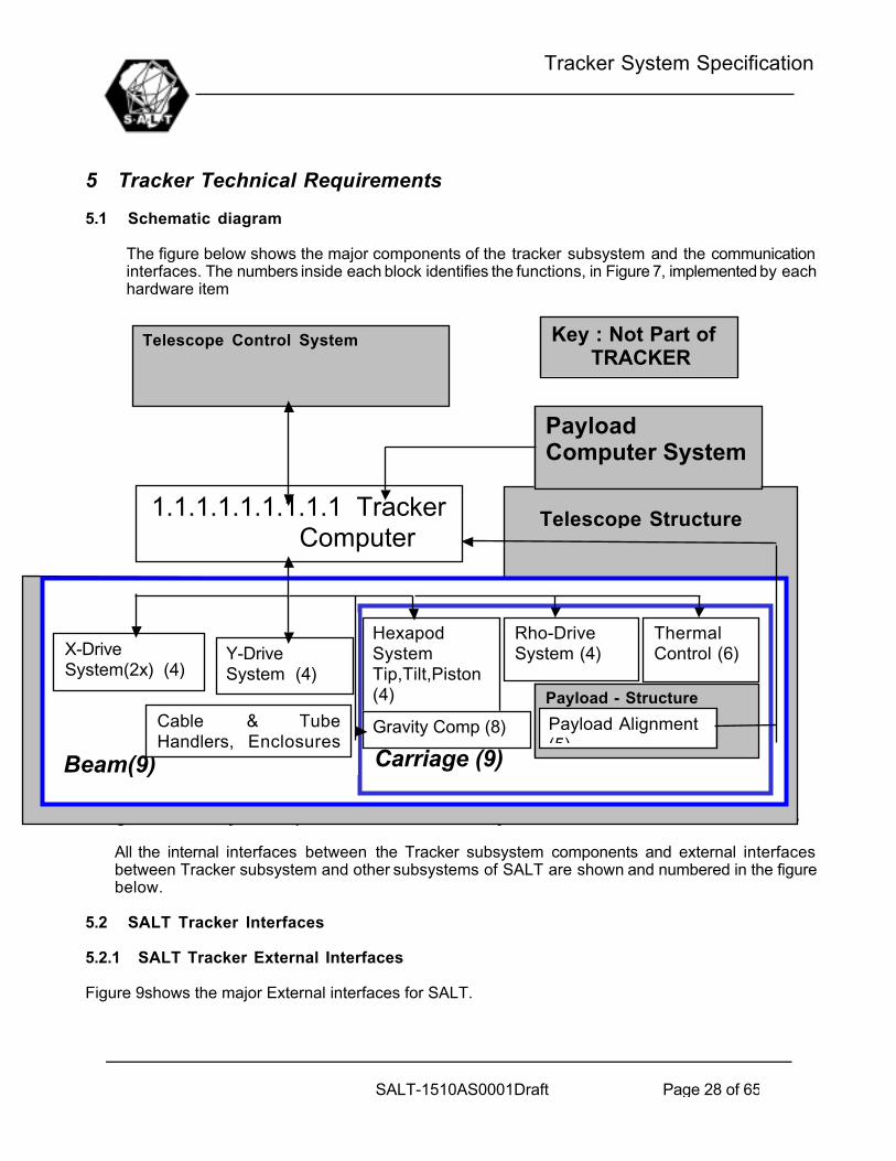
5.1 Schematic diagram
The figure below shows the major components of the tracker subsystem and the communicationinterfaces. The numbers inside each block identifies the functions, in Figure 7, implemented by eachhardware item
Figure 8. Major Components of Tracker Subsystem and Communication interfaces
All the internal interfaces between the Tracker subsystem components and external interfacesbetween Tracker subsystem and other subsystems of SALT are shown and numbered in the figurebelow.
5.2 SALT Tracker Interfaces
5.2.1 SALT Tracker External Interfaces
Figure 9shows the major External interfaces for SALT.
Telescope Control System
1.1.1.1.1.1.1.1.1 TrackerComputerSystem(1,2,3,7)
HexapodSystemTip,Tilt,Piston(4)
X-Drive System(2x) (4)
Y-DriveSystem (4)
Rho-DriveSystem (4)
Key : Not Part ofTRACKER
ThermalControl (6)
Beam(9) Carriage (9)
PayloadComputer System
Payload - Structure
Payload Alignment(5)
Cable & TubeHandlers, Enclosures(9)
Telescope Structure
Gravity Comp (8)

Tracker System Specification
SALT-1510AS0001Draft Page 29 of 65
Facility
Structure
Tracker & Payload
CommissioningInstrument
ScienceInstruments
TCS
Primary Mirror
Dome
Cooling (C)Physical (P)Data (D)Optical (O)Air (A)Electrical (E)Ventilation (V)
Key to interfaces:
1 2
10
9
4
5
7
6
8
3
11
14
12
13
15
16
17
18
External Services
19
Figure 9. Schematic showing SALT Tracker External Interfaces
The system interfaces shall comply with the Physical, Electrical and External Interface ControlDossiers referred to in Section 2
Table 7 Tracker external interfaces
No. Subsystem1
Subsystem 2 Type Direction Interface Description
8 TCS Tracker r D Both Communication cables, TrajectoryCommands, Mode Commands,Measurement Feedback,Diagnostics and Safety Feedback,Tracker MMI
2 Structure Tracker P Upper and Lower X-Drive physicalattachment at top hex ;Attachment of all cables, coolinglines, fibre optic cables runningbetween Tracker & Payload andother sub systems

Tracker System Specification
SALT-1510AS0001Draft Page 30 of 65
other sub systemsP ->
TrackerProvide Access to Tracker
E Electrical power to various partsof tracker, as per Power Budget.Both 220V and 110V AC
A Dry Air to Linear Bearings andRoller Screws
3 Facility Tracker
C Liquid cooling capacity : (TBD6)4 Tracker Primary Mirror O Optical alignment signal
Table 8 Tracker to Optical Payload interfaces (refer Figure 10)D ->
TrackerNetwork cableGuidance CorrectionsMoving Baffle Position CommandGuidance Probe CommandADC rotation Command
E Electrical power to various partsof tracker, as per Power Budget.Both 220V and 110V AC
A Dry Air to Linear Bearings andRoller Screws
e4 PayloadComputer
Tracker Computer
C Liquid cooling capacity : (TBD6)P Both Mounting on rotation stage – boltedE Electrical Connections for Data,
Power, Video CablesA ConnectionsO Connections
e5 PayloadStructure
Rho Drive
C ConnectionsP Both Mounting of sensors - Boltede6 Payload
StructurePayloadAlignment E Electrical Connections for Data,
PowerP Both Mounting of Rotation handler -
BoltedE Electrical Connections for Data,
Power, Video CablesA ConnectionsO Connections
e7 PayloadStructure
Tube & CableHandler
C ConnectionsP Both Mounting of Rotation handler -
Boltede7 Payload
StructureTube & CableHandler
E Electrical Connections for Data,Power

Tracker System Specification
SALT-1510AS0001Draft Page 31 of 65
5.2.2 SALT Tracker Internal Interfaces
Telescope ControlSystem (TCS)
T
rack
er C
om
pu
ter
Not Part of TRACKER
Hexapod System(Tip,Tilt,Piston)
XU -Drive System
Y-Drive System
Rho-Drive System
PayloadAlignment
Tra
ck
er
Be
am
Car
riag
e
T
ub
e &
Cab
le H
and
lers
& E
ncl
osu
res
Pay
load
ST
RU
CT
UR
E
INTERFACES e** : external ** : internal
10
Thermal Control1
XL -Drive System
2
3
4
5
6
7
8
All trackersubsystems9
11
12
13
14
e5
e6
15
16
17
e1
e3
e4
e7
e2
Tracker System Specification
SALT-1510AS0001Draft Page 32 of 65
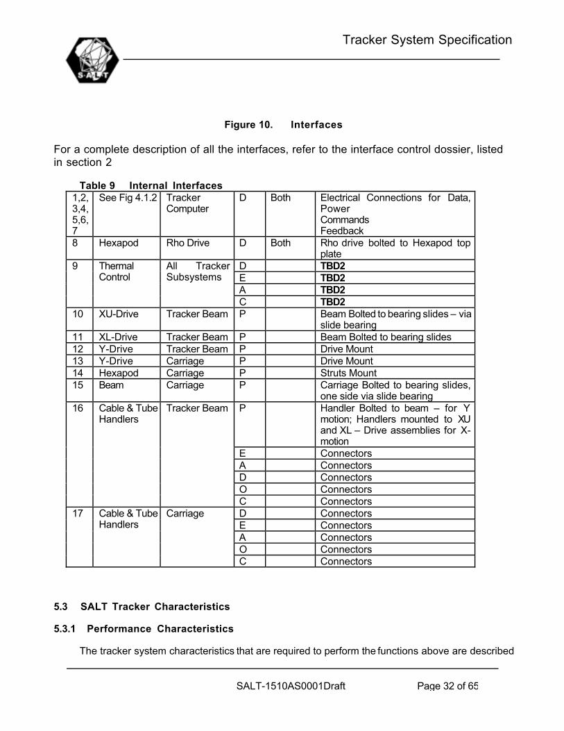
Figure 10. Interfaces
For a complete description of all the interfaces, refer to the interface control dossier, listedin section 2
Table 9 Internal Interfaces1,2,3,4,5,6,7
See Fig 4.1.2 TrackerComputer
D Both Electrical Connections for Data,PowerCommandsFeedback
8 Hexapod Rho Drive D Both Rho drive bolted to Hexapod topplate
D TBD2E TBD2A TBD2
9 ThermalControl
All TrackerSubsystems
C TBD210 XU-Drive Tracker Beam P Beam Bolted to bearing slides – via
slide bearing11 XL-Drive Tracker Beam P Beam Bolted to bearing slides12 Y-Drive Tracker Beam P Drive Mount13 Y-Drive Carriage P Drive Mount14 Hexapod Carriage P Struts Mount15 Beam Carriage P Carriage Bolted to bearing slides,
one side via slide bearingP Handler Bolted to beam – for Y
motion; Handlers mounted to XUand XL – Drive assemblies for X-motion
E ConnectorsA ConnectorsD ConnectorsO Connectors
16 Cable & TubeHandlers
Tracker Beam
C ConnectorsD ConnectorsE ConnectorsA ConnectorsO Connectors
17 Cable & TubeHandlers
Carriage
C Connectors
5.3 SALT Tracker Characteristics
5.3.1 Performance Characteristics
The tracker system characteristics that are required to perform the functions above are described

Tracker System Specification
SALT-1510AS0001Draft Page 33 of 65
below:
5.3.1.1 MOTION RANGES
The coordinate system used below is the Ideal Tracker Frame(ITF).
Table 10 Coordinate systemNo Axis(ITF) Units Range + Tolerance - Tolerancea X mm 3000 100 0b Y mm 3000 100 0c Z mm 180 20 0d q, about Y deg 12 2 0e f, about X deg 12 2 0f r, about Z deg 230 5 0
Any combination of these motions must be achievable.
Figure 11. View of tracker on upper hex
5.3.1.2 MOTION SYMMETRY
The Ranges in 4.3.1.1 are symmetrically spaced about the ITF Origin with the followingmaximum errors:
Table 11 Maximum errorsNo Axis(ITF) Units + Tolerance - Tolerancea X mm 10 -10

Tracker System Specification
SALT-1510AS0001Draft Page 34 of 65
b Y mm 10 -10c Z mm 2 -2d q, about Y deg 0.1 -0.1e f, about X deg 0.1 -0.1f r, about Z deg 1 -1
5.3.1.3 SPEED
The coordinate system used below is the Ideal Tracker Frame(ITF).
Table 12 Tracker speedNo Axis(ITF) Units Min
SpeedMaxSpeed(+ or -)
+Tolerance
-Tolerance
i SLEWINGa X mm/s 0 70 10 0b Y mm/s 0 70 10 0c Z mm/s 0 3 0.5 0d q, about Y deg/s 0 0.3 0.1 0e f, about X deg/s 0 0.3 0.1 0f r, about Z deg/s 0 5 1 0ii TRACKINGa X mm/s 0 2 0.5 0b Y mm/s 0 2 0.5 0c Z mm/s 0 1.3 0.5 0d q, about Y asec/
s0 30 5 0
e f, about X asec/s
0 30 5 0
f r, about Z deg/s 0 1 0.5 0
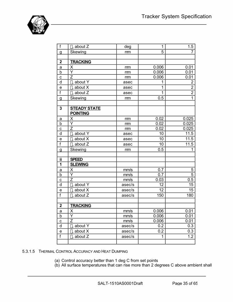
5.3.1.4 ACCURACY (TBC9)
Table 13 Tracker accuracyNo Axis(ITF) Units RMS Error Max Errori POSITION1 SLEWINGa X mm 1 1.5b Y mm 1 1.5c Z mm 1 1.5d q, about Y deg 1 1.5e f, about X deg 1 1.5
Tracker System Specification
SALT-1510AS0001Draft Page 35 of 65
f r, about Z deg 1 1.5g Skewing mm 5 7
2 TRACKINGa X mm 0.006 0.01b Y mm 0.006 0.01c Z mm 0.006 0.01d q, about Y asec 1 2e f, about X asec 1 2f r, about Z asec 1 2g Skewing mm 0.5 1
3 STEADY STATEPOINTING
a X mm 0.02 0.025b Y mm 0.02 0.025c Z mm 0.02 0.025d q, about Y asec 10 11.5e f, about X asec 10 11.5f r, about Z asec 10 11.5g Skewing mm 0.5 1
ii SPEED1 SLEWINGa X mm/s 0.7 5b Y mm/s 0.7 5c Z mm/s 0.03 0.5d q, about Y asec/s 12 15e f, about X asec/s 12 15f r, about Z asec/s 150 180
2 TRACKINGa X mm/s 0.006 0.01b Y mm/s 0.006 0.01c Z mm/s 0.006 0.01d q, about Y asec/s 0.2 0.3e f, about X asec/s 0.2 0.3f r, about Z asec/s 1 1.2
5.3.1.5 THERMAL CONTROL ACCURACY AND HEAT DUMPING
(a) Control accuracy better than 1 deg C from set points(b) All surface temperatures that can rise more than 2 degrees C above ambient shall
Tracker System Specification
SALT-1510AS0001Draft Page 36 of 65
be actively controlled.
5.3.1.6 CONTROL LOOP REQUIREMENTS
All Control loops shall satisfy the following stability requirements under all loading conditions:• Phase margin: > 50 degrees• Gain Margin: > 8dB• Maximum Overshoot : < 2%• Maximum Bandwidth x- Axis < 1Hz• Maximum Bandwidth y- Axis < 2Hz• Maximum Bandwidth z- Axis < 2Hz• Maximum Bandwidth q - Axis < 2Hz• Maximum Bandwidth f - Axis < 2Hz• Maximum Bandwidth r - Axis < 2Hz• Settling time (TBD7)
5.3.1.7 SAFETY
The following should be read in conjunction with the SALT Safety Analysis, SALT-1000AA0030, listed in section 2All single point failures that can lead to loss of life, serious injury to personnel or damage toequipment shall be identified and the design modified to prevent such failures.In no case shall it be possible for a component or control system failure to cause thetracker beam to disengage the X ways or for any other component or piece to detach anddrop from the Tracker Assembly.Motor overload protection, fusing and sensing shall be implemented and monitored by thecontrol system to ensure that failure mode criteria are met.Beam skew protection shall be independent of encoder measurements which shall initiatesystem breaking and shutdown for skew in excess of 0.75mm from nominal.Beam skew protection shutdown shall stop both ends of Tracker Beam within a maximumtravel of 50mm from full slew speed,not increasing skewing by more than 20mm and within5mm from maximum tracking speed,not increasing skewing by more than 3mm.Where tools must be used on-telescope for servicing and maintenance, they shall besecured by lanyards to the servicer’s tool belt or manlift.All fasteners, cover panels and other components which can be accessed while thetracker is on telescope shall be captivated by the use of _ turn captured fasteners, wireloop, bails, threads or some other like means to prevent accidental injury to personnelbelow as well as damage to primary mirror.No lock washers shall be used for on-telescope accessible fasteners, chemical lockingcompounds or aircraft-type locking nuts shall be used instead.A safety analysis and design shall be presented and implemented to satisfy all safetyrequirements.
5.3.1.8 STRUCTURAL FREQUENCIES (TBC10)
The following frequencies apply to the tracker beam with payload integrated and positionedat the centre of the beam.
Table 14 Structural dynamics

Tracker System Specification
SALT-1510AS0001Draft Page 37 of 65
Degree of Freedom(ITF)
Mode Minimum Frequency[Hz]
X 1 10Y 1 10Z 1 10Rotation about X 1 10Rotation about Y 1 7Rotation about Z 1 7
5.3.1.9 STATIC STRUCTURAL DEFLECTIONS (TBC11)
The following maximum deflections of the Tracker beam under its own weight and a steadystate wind force of 50kg, with the payload installed, shall be allowed. The payload positionshall be at the centre of the beam and the orientation of the payload can be anywherewithin the operational envelope. The action point of the wind force is maximally 500mm(TBC12) above the Tracker Beam(ie Z=-500mm in ITF) and can be directed along X and Z.
Table 15 Structural deflections: staticDegree of Freedom(ITF)
Units MaximumDisplacement
X um 100Y um 100Z um 5000Rotation about X arcsec 10Rotation about Y arcsec 10Rotation about Z arcsec 10
5.3.1.10 DYNAMIC STRUCTURAL DEFLECTIONS
The following maximum deflections of the Tracker beam under dynamic forces such as windand control system induced, shall be allowed. The payload position shall be at the centre ofthe beam and the orientation of the payload can be anywhere within the operational envelope.The varying component of the wind shall be less than 20kg, at the same action point as in4.3.1.10. The frequency of the wind force is less than 1 Hz.
Table 16 Structural deflections: dynamicDegree of Freedom(ITF)
Units MaximumDisplacement
X um 10Y um 10Z um 10Rotation about X arcsec 1Rotation about Y arcsec 1Rotation about Z arcsec 3
5.3.1.11 ORTHOGONALITY OF AXES : (TBC13)

Tracker System Specification
SALT-1510AS0001Draft Page 38 of 65
Table 17 Orthogonality of Axes : After correction by mount modelAxes (ITF) Units ValueXY arcsec 1XY Plane and Z axis arcsec 1Rotation about Y, non parallelismof rotation axis and Y-Axis
arcsec 1
Rotation about X, non parallelismof rotation axis and X-Axis
arcsec 1
Rho rotation, non parallelism to ZAxis
arcsec 1
Rho Rotation Axis offset from ZAxis
um 2
Table 18 Orthogonality of Axes : ManufacturingAxes (ITF) Units ValueXY arcsec 200XY Plane and Z axis arcsec 200Rotation about Y, non parallelismof rotation axis and Y-Axis
arcsec 200
Rotation about X, non parallelismof rotation axis and X-Axis
arcsec 200
Rho rotation, non parallelism to ZAxis
arcsec 200
Rho Rotation Axis offset from ZAxis
um 20
The purpose of this specification is to ensure that the operating envelope of tracker is notskewed unlimited
5.3.1.12 ROTATION POSITION OF PAYLOAD (TBC14)
(a) The Payload shall be rotated (q,f) nominally about the paraxial focus of theprimary mirror. This translates to a rotation point in ITF of X=0,Y=0,Z=800mm
(b) The rotation point should be variable with +- 200mm about the nominal position
5.3.1.13 MAXIMUM ACCELERATION AND JERK
(TBD8)
5.3.1.14 ADDITIONAL SEARCH SPEEDS
(TBD9)
5.3.1.15 FORCES IN HEXAPOD STRUTS
The struts shall be designed, positioned and actuated such that the force in any strut neverchanges direction.

Tracker System Specification
SALT-1510AS0001Draft Page 39 of 65
5.3.1.16 TRAVEL LIMITS
(TBD10)
5.3.1.17 PAYLOAD ALIGNMENT
(TBD11)
5.3.1.18 TRACKER MMI
(TBD5)
5.3.2 Physical Characteristics
5.3.2.1 OBSCURATION
Tracker Shadow on Primary mirror :• On - Axis < 3m2
• 8.5 deg Off - Axis < 5m2
5.3.2.2 MASS
The total tracker mass shall be less than 3750kg (TBC15)The payload mass shall be less than 750kg (TBC16)
5.3.2.3 MAXIMUM SURFACE TEMPERATURES
Any gradient in the air temperature within the optical path will have a negative influence onthe image quality produced by SALT. In order to minimise this effect, the followingconstraints are imposed. Relaxation of these constraints may be allowed on a case-by-case basis, subject to meeting the overall seeing objectives. {These values are all(TBC20)}
Section 5.5 provides further guidance in this regard.
5.3.2.3.1 Objects in the optical path
All items of equipment that are within 1m of the telescope optical path or within a verticalcylinder defined as a vertical extension of the pier to the highest point of the top hex,shall comply with the following:
a. No item exposed to the ambient air, regardless of its size, shall have a surfacetemperature of more than 8ºC above ambient.
b. No item having forced-air cooling shall blow the exhausted air into the ambient air.c. Items with a surface temperature of more than 2ºC above ambient shall have a
Thermal Factor (TF) of less than 0.6 m2C, where TF is defined as follows:
TF = A__T

Tracker System Specification
SALT-1510AS0001Draft Page 40 of 65
Where A = Exposed surface area of the item in m2
_T = Temperature difference between the items exposed surface and the ambient airtemperature in ºC
NOTE: In practice, these constraints mean that many items may require cooling jacketsor cooled enclosures. As an example, an item measuring 0.4x0.4x0.4m emitting morethan about 4W of heat continuously, will need to be insulated and cooled otherwise itssurface temperature will go above the allowed limit.
5.3.2.3.2 Objects outside the optical path
All items of equipment that are within the telescope “chamber” but not included in5.3.2.3.1 shall comply with the following:
a. No item exposed to the ambient air, regardless of its size, shall have a surfacetemperature of more than 8ºC above ambient.
b. No item having forced-air cooling shall blow the exhausted air into the ambient air.c. Items with a surface temperature of more than 3ºC above ambient shall have a
Thermal Factor (TF) of less than 2 m2C (with TF defined in 5.3.2.3.1).d. Large areas such and the floor and azimuth pier must not have a heat transfer
coefficient of more than 3W/m2K.
NOTE: In practice, these constraints mean that many items may require cooling jacketsor cooled enclosures. As an example, an item measuring 0.4x0.4x0.4m emitting morethan about 6.5W of heat continuously, will need to be insulated and cooled otherwise it’ssurface temperature will go above the allowed limit.
5.3.2.4 MINIMUM SURFACE TEMPERATURES
Any gradient in the air temperature within the optical path will have a negative influence onthe image quality produced by SALT. In order to minimise this effect, the followingconstraints are imposed. Relaxation of these constraints may be allowed on a case-by-case basis, subject to meeting the overall seeing objectives. These constraints shall be metfor the 98th percentile of operation ambient conditions {these values are all (TBC20)}
Section 5.5 provides further guidance in this regard.
5.3.2.4.1 Objects in the optical path
All items of equipment that are within 1 meter of the telescope optical path or directlyabove the primary mirror, shall comply with the following:
a. No item exposed to the ambient air, regardless of its size, shall have a surfacetemperature cooler than 2ºC below ambient to prevent condensation on surfaces.
b. No item shall blow exhausted cool air into the ambient air.
5.3.2.4.2 Objects outside the optical path

Tracker System Specification
SALT-1510AS0001Draft Page 41 of 65
All items of equipment that are within the telescope “chamber” but not included in5.3.2.4.1 shall comply with the following:
a. No item exposed to the ambient air, regardless of its size, shall have a surfacetemperature cooler than 3ºC below ambient.
b. No item shall blow exhausted cool air into the ambient air
5.3.2.5 COMPONENT/MODULE REPLACEMENT
All major components that might need removal, must provide for interfaces suitable forusing the dome crane as lifting device.Any special lifting or handling fixtures for modules by their nature or orientation requiresuch fixtures for safe lifting and positioning.
5.3.2.6 PAYLOAD CLEARANCE AND ENVELOPE
(TBD12)
5.3.3 Environmental Requirements
5.3.3.1 NORMAL OPERATIONAL ENVIRONMENT
SALT shall meet all the requirements specified in this document when operated in the night-time outside ambient condition defined in Table 19 below:
Table 19 Normal Operational EnvironmentParameter Value NotesMinimum Temperature -5ºCMaximum Temperature 20ºCMaximum nightly temperature range 8ºC TBC21Maximum rate environment cooling -1.5ºC/hMaximum rate of environment warming +0.5ºC/h Estimated valueMinimum Humidity 5%Maximum Humidity 97% Non-condensingMaximum wind velocity 16.8 m/s Gusts up to 22 m/s TBC17Site altitude 1798mSolar radiation 0 W/m2 Twilight to dawn
5.3.3.2 MARGINAL OPERATIONAL ENVIRONMENT
The degradation of system performance as a result of the ambient environment specified inTable 20 below, shall not exceed 10% (TBC18) of the nominal values in paragraph 5.3.1
Table 20 Marginal Operational EnvironmentParameter Value NotesMinimum Temperature -10ºCMaximum Temperature 25ºC

Tracker System Specification
SALT-1510AS0001Draft Page 42 of 65
Maximum rate environment cooling -2.0ºC/hMaximum rate of environment warming +1ºC/h Estimated valueMinimum Humidity 5%Maximum Humidity 97% Non-condensingMaximum wind velocity 21 m/s Gusts up to 25 m/s (TBC17)Solar radiation 0 W/m2 Twilight to dawn
5.3.3.3 SURVIVAL ENVIRONMENT
SALT shall survive when exposed to the day or night ambient environment specified inTable 21 below. Note that the dome and louvers will be closed under these conditions.
Table 21 SALT Survival Operating EnvironmentParameter Value NotesMinimum Temperature -20ºC**Maximum Temperature 45ºC**Maximum Humidity 100% Occasional exposure to condensing
conditionsMaximum wind velocity 61 m/s**Rain Note 1Snow Note 1Hail Note 1Icing Present Low temperatures after
condensation or rain are common.Solar Radiation Note 1Other Note 1NOTES:
1. Environmental conditions not specified shall be obtained from the appropriatebuilding/civil standards suitable for Sutherland.
2. **: Use the worst case of these figures and those specified in the appropriatebuilding/civil standards.
5.4 Operation and Maintenance Requirements
5.4.1 Packaging, handling, storage
Packaging, handling and storage requirements will be determined for each individual type ofcomponent, taking into account the specific requirements of the component, the method ofshipping and interim storage locations. Storage at SALT will be in the SALT Store Room, indry, air-conditioned conditions. Containers shall be sufficient for one return shipping only,unless otherwise specified.
5.4.2 Product Documentation
The SALT System shall include a set of SALT specific operating instructions, training manuals,maintenance manuals and calibration procedures at system and subsystem level. Componentlevel documentation will be specified on individual basis, within the following guideline: ForCOTS equipment, the standard manufacturers documentation will be supplied, and no special

Tracker System Specification
SALT-1510AS0001Draft Page 43 of 65
documentation will be developed. For custom made equipment, a set of documentation will bespecified and will form part of the deliverable. All documentation shall be in English.
5.4.3 Personnel and Training
5.4.3.1 OPERATION
SALT will be operated from the control room at the telescope. A SALT operator (SO) and aSALT Astronomer (SA) will be on duty during the whole night, for every operational night. Any ad hoc repair work will be performed by the SAAO standby maintenance staff, to becalled by the SO when required. The SO will have a National Diploma (N6/S3) or equivalentqualification in electronic or mechanical engineering or have adequate experience. The SAwill be a PhD astronomer.
5.4.3.2 MAINTENANCE
SALT will be maintained by the SAAO staff at Sutherland and Cape Town. Personnel willbe trained in the maintenance of SALT, and be granted a “SALT – license” upon completionof training. All maintenance work carried out on SALT will be supervised/signed off by aSALT licensed person. It is anticipated that the following people will be required to maintainSALT:
At Sutherland:Mechanical Technician: 2Electronic Technician: 1Electrical Technician: 1In Cape Town:Mechanical Engineer: 1Electronic Engineer: 1Software Engineer: 1
These positions should not be SALT only, i.e. these personnel must be part of the SAAOtechnical staff, who will also work on the other SAAO telescopes. Thus, two Electronictechnicians, each working 50% on SALT, can constitute the one full time ElectronicTechnician listed above.
One mechanical and one of the electrical/electronic technician will also required to be onstandby during every night of operations. These standby personnel will form part of thenormal SAAO standby team.
In the above requirements, “Technicians” require a N6, T3 or equivalent qualification, and“Engineer” means an S6 or Bachelors degree in Engineering and/or Computer Science.
5.4.4 Availability
5.4.4.1 SCIENCE EFFICIENCY
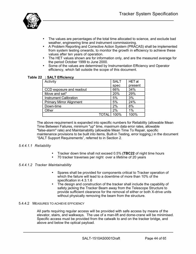
Table 22 below specifies the required SALT efficiency for various operational aspects.
Tracker System Specification
SALT-1510AS0001Draft Page 44 of 65
• The values are percentages of the total time allocated to science, and exclude badweather, engineering time and instrument commissioning.
• A Problem Reporting and Corrective Action System (PRACAS) shall be implementedfrom system testing onwards, to monitor the growth in efficiency to achieve thesevalues after ten years of operation.
• The HET values shown are for information only, and are the measured average forthe period October 1999 to June 2000.
• Some of the values are determined by Instrumentation Efficiency and Operatorefficiency, which fall outside the scope of this document.
Table 22 : SALT EfficiencyActivity SALT
specHET atpresent
CCD exposure and readout 66% 34%Move and set* 20% 29%Instrument Calibration 5% 3%Primary Mirror Alignment 5% 24%Down-time 2% 8%Other 2% 1%
TOTAL 100% 100%
The above requirement is expanded into specific numbers for Reliability (allowable MeanTime Between Failures, minimum "up" time, maximum data error rates, allowable"false-alarm" rate) and Maintainability (allowable Mean Time To Repair, specificmaintenance provisions to be built into items, Built-in Testing, error logging,) in the document“SALT Support Requirements”, referred to in Section 2.
5.4.4.1.1 Reliability
• Tracker down time shall not exceed 0.5% (TBC22 of night time hours• 70 tracker traverses per night over a lifetime of 20 years
5.4.4.1.2 Tracker Maintainability
• Spares shall be provided for components critical to Tracker operation ofwhich the failure will lead to a downtime of more than 10% of thespecification in 4.3.1.6
• The design and construction of the tracker shall include the capability ofsafety jacking the Tracker Beam away from the Telescope Structure toprovide sufficient clearance for the removal of either or both X-drive unitswithout physically removing the beam from the structure.
5.4.4.2 MEASURES TO ACHIEVE EFFICIENCY
All parts requiring regular access will be provided with safe access by means of theelevator, stairs, and walkways. The use of a man-lift and dome-crane will be minimised. Specific access must be provided from the catwalk to and on the tracker bridge, andabove and below the optical payload.

Tracker System Specification
SALT-1510AS0001Draft Page 45 of 65
Subsystems shall be organized into modules for ease of mounting/dismounting andservicing.
COTS equipment will be used as far as possible to reduce spares holding requirements. Afloat level of standard spares (bolts, nuts, wires, oils, grease) will be kept in the SALTStore.
As far as possible local support for all subsystems/components is required
Special tools and equipment required for system operation and maintenance shall be kept toa minimum, and will be provided with each subsystem.
All normal maintenance actions will be able to be completed within one working day, unlessotherwise specified. Where maintenance actions take more than a day and happenregularly (e.g. primary mirror coating), enough spares will be held to ensure that theoperation of the telescope system is not affected.
Two (TBC23) standard (metric) tool sets will be available, one in the SALT workshop andone in the telescope chamber. Special tools will be kept to a minimum, and be limited tomirror handling and coating.
5.5 Design and Construction constraints
5.5.1 General design guidelines and constraints
The following guidelines and constraints apply to SALT (where these general guidelinescontradict specific requirements in other parts of this document, the other requirements shallhave precedence):
a. Every part of SALT that is exposed to direct sunlight will be shielded, have a double wall,and/or be made from a material which has a low thermal inertia.
b. The area around the circular telescope building will be disturbed as little as possible (e.g.minimum buildings, paving, levelling), and the natural vegetation will be preserved.
c. Preference will be given to material with low thermal inertia and open section (e.g. I-beamrather than tube) for anything above the telescope chamber floor.
d. The telescope chamber shall not be heated by adjacent rooms, i.e. any rooms underneathor next door which are heated, shall be thermally isolated from the telescope chamber.
e. The telescope chamber shall have the same temperature as the ambient air during observing,i.e. it shall be cooled during the day, to match ambient temperature at the start of observing
f. No warm air will be exhausted directly from the building.g. Commercial, off the shelf (COTS) equipment will be used unless specifically stated
otherwise.h. All computer hardware will be COTS equipment, using “mainstream” equipment and vendors.i. Computer operating system and application software will be COTS, using “mainstream”
packages and vendorsj. Optical fibres will be used for any digital communications travelling more than 30mk. No artificial light will intrude into the telescope chamber, or outside the building during
observation.
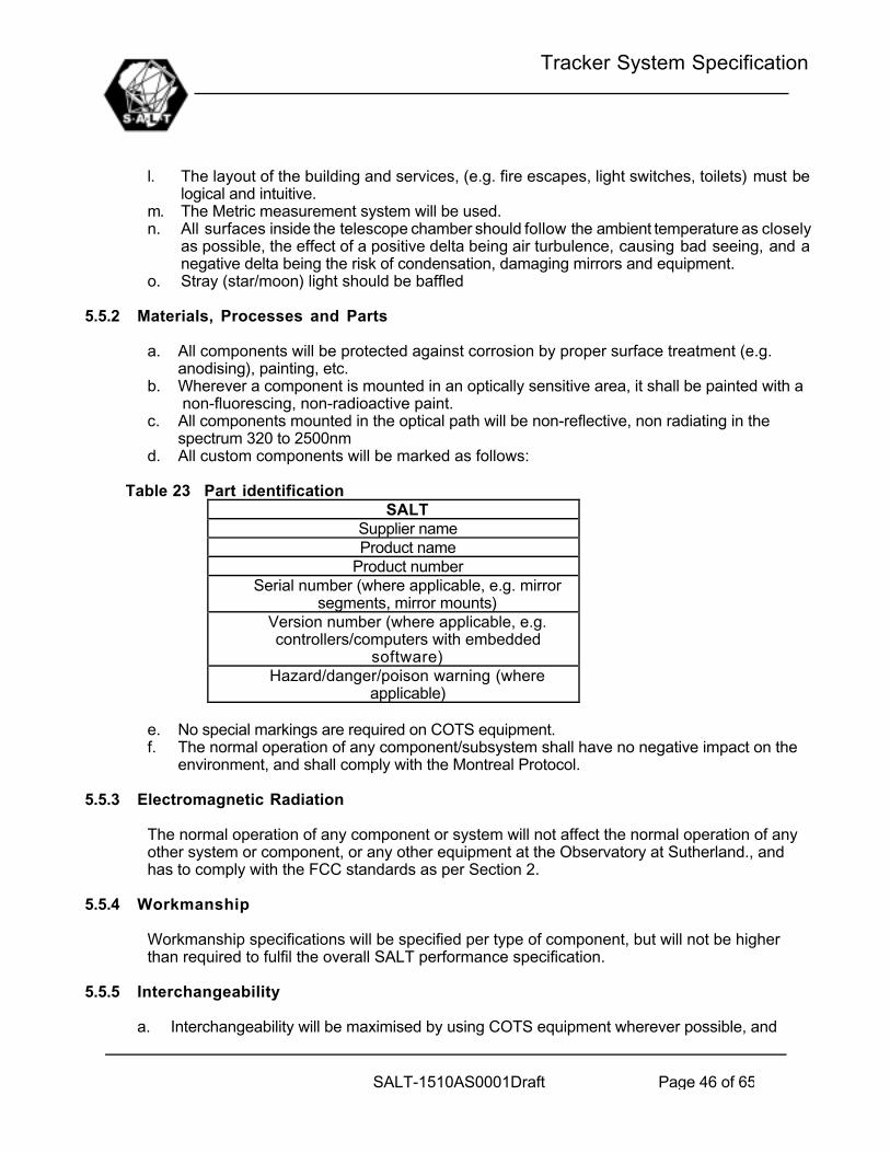
Tracker System Specification
SALT-1510AS0001Draft Page 46 of 65
l. The layout of the building and services, (e.g. fire escapes, light switches, toilets) must belogical and intuitive.
m. The Metric measurement system will be used.n. All surfaces inside the telescope chamber should follow the ambient temperature as closely
as possible, the effect of a positive delta being air turbulence, causing bad seeing, and anegative delta being the risk of condensation, damaging mirrors and equipment.
o. Stray (star/moon) light should be baffled
5.5.2 Materials, Processes and Parts
a. All components will be protected against corrosion by proper surface treatment (e.g.anodising), painting, etc.
b. Wherever a component is mounted in an optically sensitive area, it shall be painted with a non-fluorescing, non-radioactive paint.
c. All components mounted in the optical path will be non-reflective, non radiating in thespectrum 320 to 2500nm
d. All custom components will be marked as follows:
Table 23 Part identificationSALT
Supplier nameProduct name
Product numberSerial number (where applicable, e.g. mirror
segments, mirror mounts)Version number (where applicable, e.g.controllers/computers with embedded
software)Hazard/danger/poison warning (where
applicable)
e. No special markings are required on COTS equipment.f. The normal operation of any component/subsystem shall have no negative impact on the
environment, and shall comply with the Montreal Protocol.
5.5.3 Electromagnetic Radiation
The normal operation of any component or system will not affect the normal operation of anyother system or component, or any other equipment at the Observatory at Sutherland., andhas to comply with the FCC standards as per Section 2.
5.5.4 Workmanship
Workmanship specifications will be specified per type of component, but will not be higherthan required to fulfil the overall SALT performance specification.
5.5.5 Interchangeability
a. Interchangeability will be maximised by using COTS equipment wherever possible, and

Tracker System Specification
SALT-1510AS0001Draft Page 47 of 65
exceptions will be specified.b. All primary mirror segments and supports will be interchangeable i.t.o. position on the
mirror truss, but mirrors and mirror mounts will be matched.
5.5.6 Safety
5.5.6.1 SAFETY-CRITICAL FAILURES
All single-point failures that can lead to loss of life, serious injury to personnel or damage toequipment shall be identified and the design modified to prevent such failures.
A preliminary safety analysis to identify such potential failures is contained in the SALTSafety Analysis referred to in section 2.
5.5.6.2 SOFTWARE SAFETY
Where the malfunction of software alone could cause a safety-critical failure, alternatemeans shall be provided to prevent the occurrence of such a failure. This would typicallytake the form of electrical interlocks designed in a fail-safe manner.
5.5.6.3 SAFE INITIALISATION
All systems, when initialising from power-up or when reset, shall be in a safe, non-activestate (e.g. equipment stationary, drives off). It shall take a specific command from the TCS(by exception) or the operator via the TCS, to proceed with potentially unsafe actions(such as rotating the structure or dome, moving the tracker or opening/closing the shutter).
5.5.6.4 LOCAL ELECTRIC OPERATION
A means shall be provided at the relevant electrical panel, to control critical equipment manually,even in the event of a Controller failure. A selection switch on the panel shall select either“Automatic” or “Manual” control. The status of this switch shall enable/disable the manual controlfunctions on the panel and shall be reported to the TCS.
“Critical Equipment” is equipment identified in the Safety Analysis document as requiring thisfunction to achieve safe operation (e.g. dome shutter).
5.5.7 Ergonomics
Comfortable working positions and conditions will be provided at all stations where operatorswill spend long times regularly during normal operation.
5.5.8 Special commissioning requirements
5.5.8.1 SUBSYSTEM MMI’S
There shall be monitors/keyboards plus good human interface SW at the subsystemcomputers, for use during system commissioning. These controls must include facilities foroverriding automatic functions and monitoring of information communicated to/from the TCS.

Tracker System Specification
SALT-1510AS0001Draft Page 48 of 65
5.5.8.2 TEST POINTS
Means shall be provided to measure electrical signals and interpret data transferredbetween subsystems and major electronic items within each subsystem.
5.5.8.3 TEST DATA
Each subsystem shall send to the TCS the values of all internal variables that may need tobe interrogated during commissioning and testing, but would not normally be needed fortelescope control by the TCS. A list of typical variables required is provided below, butdetails will be provided in the SALT Electrical Interface Control Dossier:
5.5.8.4 SPOTTER TELESCOPE
A small telescope pointing at the sky and aligned parallel to the SAC axis, shall bepermanently mounted on the tracker. It shall be fitted with a removable video camera at theeyepiece linked to a monitor in the Control Room. The FOV of this telescope shall bedetermined prior to commissioning, once its role has been fully defined.
5.5.9 Software
Each subsystem shall comply to the requirements defined in SALT Computer SoftwareStandard referred to in Section 2.
This document addresses the following:• Software must separate H/W interfaces with functional software, so that I/O devices can be
replaced later without having to modify all the software• The acceptable languages and operating systems will be specified per computer plus general
interfacing requirements• Specific practices and documentation/design requirements for the software will be defined• Protocols for interfacing between computers will be defined (detail will be in ICD)• Format for PLC software• Each computer shall report the health status of itself and all it’s input/output devices to a
higher level computer, such that the TCS will be notified all major failures.• TCS shall monitor communication health to all systems (ping test?)
5.5.10 Computer Hardware
Each subsystem shall comply to the requirements defined in SALT Computer HardwareStandard referred to in Section 2.
This document addresses the following:• Hardware must be selected such that it is possible to upgrade the PC’s at a later stage• Acceptable types of PLC’s servo drives, axis controllers and amplifiers will also be specified
5.5.11 Electrical Design
5.5.11.1 UPS
Tracker System Specification
SALT-1510AS0001Draft Page 49 of 65
5.5.11.1.1 Installed Capacity
The total installed UPS capacity shall be at least the value indicated in the Power Budget(Appendix C) plus 20%.
5.5.11.1.2 Use of UPS power
The following items will be placed on UPS power:• All computer systems and PLC’s• Safety monitoring equipment (e.g. dome open-close indication)• Sensitive instrumentation
5.5.11.1.3 General UPS Requirements
The UPS shall have the following features:• It’s battery charge level and overall health shall be monitored by the TCS, with
operator warnings as appropriate.• A “power-fail” signal shall be passed to the TCS from the UPS to indicate the loss of
normal power so that contingency software can be activated• The UPS shall not increase electrical noise on the normal power line but rather
provide a filter to protect its load from the Sutherland electrical supplycharacteristics.
5.5.11.2 STANDBY POWER GENERATORS
5.5.11.2.1 Use of Emergency Power
All essential power uses shall be provided with Emergency Power during a normalpower failure. The definition of “essential” is (TBD20), but may mean excluding highpower users such as air-conditioning.
5.5.11.2.2 General Emergency Power Requirements
The emergency power source shall have the following features:• It shall become active within 30s of a general power failure and will remain on until
manually turned off• The quality of power (voltage, frequency drift, harmonics) shall be no worse than
the normal electrical supply• A signal from the emergency generator to the TCS shall indicate when normal power
has failed.• At least the following error conditions shall also be reported to the UPS: low fuel,
low oil pressure, generator fault, low voltage, over-current, system overheating• The system shall have interlocks to prevent damage from the above faults• The fuel capacity shall be sufficient to provide at least 15h of continuous operation.
5.5.11.3 CABLE SIZING
All electrical power cables shall be sized such that their outside surface temperature does
Tracker System Specification
SALT-1510AS0001Draft Page 50 of 65
not rise above ambient by more than 0.5ºC under worst-case operating loads.
5.5.11.4 GENERAL ELECTRICAL REQUIREMENTS
All subsystems shall comply with the SALT Electrical Requirements. This document willaddress the following:• Earthing and bonding of electrical equipment• Measures to minimise electrical interference• General principle to follow for electrical parts of each subsystem
5.5.12 Future growth
The following potential growth areas shall be borne in mind during the design process andaccommodated where this does not have an impact on the achievement of the immediateperformance, schedule and cost requirements.
5.5.12.1 REMOTE OBSERVING
The control room of SALT may be required to be duplicated at the SAAO in Cape Town, toallow remote operating of SALT.
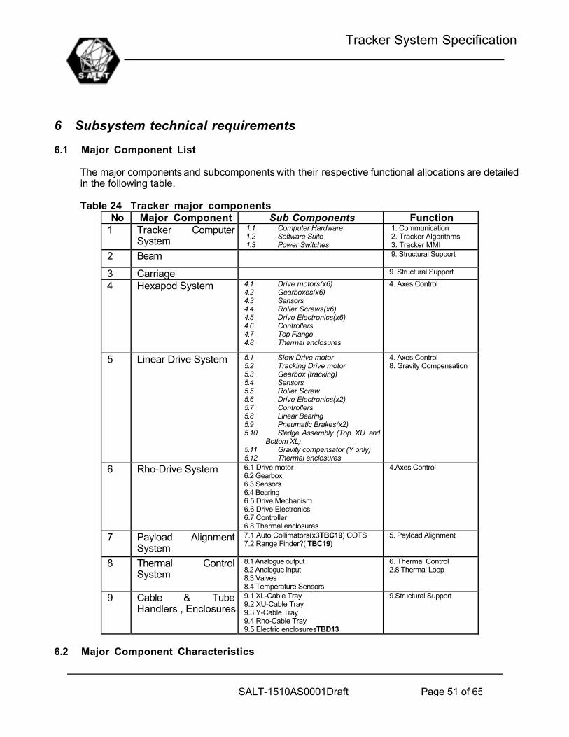
Tracker System Specification
SALT-1510AS0001Draft Page 51 of 65
6 Subsystem technical requirements
6.1 Major Component List
The major components and subcomponents with their respective functional allocations are detailedin the following table.
Table 24 Tracker major componentsNo Major Component Sub Components Function
1 Tracker ComputerSystem
1.1 Computer Hardware1.2 Software Suite1.3 Power Switches
1. Communication2. Tracker Algorithms3. Tracker MMI
2 Beam 9. Structural Support
3 Carriage 9. Structural Support
4 Hexapod System 4.1 Drive motors(x6)4.2 Gearboxes(x6)4.3 Sensors4.4 Roller Screws(x6)4.5 Drive Electronics(x6)4.6 Controllers4.7 Top Flange4.8 Thermal enclosures
4. Axes Control
5 Linear Drive System 5.1 Slew Drive motor5.2 Tracking Drive motor5.3 Gearbox (tracking)5.4 Sensors5.5 Roller Screw5.6 Drive Electronics(x2)5.7 Controllers5.8 Linear Bearing5.9 Pneumatic Brakes(x2)5.10 Sledge Assembly (Top XU and
Bottom XL)5.11 Gravity compensator (Y only)5.12 Thermal enclosures
4. Axes Control8. Gravity Compensation
6 Rho-Drive System 6.1 Drive motor6.2 Gearbox6.3 Sensors6.4 Bearing6.5 Drive Mechanism6.6 Drive Electronics6.7 Controller6.8 Thermal enclosures
4.Axes Control
7 Payload AlignmentSystem
7.1 Auto Collimators(x3TBC19) COTS7.2 Range Finder?( TBC19)
5. Payload Alignment
8 Thermal ControlSystem
8.1 Analogue output8.2 Analogue Input8.3 Valves8.4 Temperature Sensors
6. Thermal Control2.8 Thermal Loop
9 Cable & TubeHandlers , Enclosures
9.1 XL-Cable Tray9.2 XU-Cable Tray9.3 Y-Cable Tray9.4 Rho-Cable Tray9.5 Electric enclosuresTBD13
9.Structural Support
6.2 Major Component Characteristics

Tracker System Specification
SALT-1510AS0001Draft Page 52 of 65
6.2.1 Tracker Computer System
The computer system shall be located in the computer room in the Facility. The maximum wirelength between the Computer Room and the top of the Telescope Structure will be less than80m.This room will be maintained at temperatures between 5 to 25 degrees C and relative humidity5% to 95%.
The Tracker Computer System shall perform all functions reliably in this environment.
6.2.1.1 COMPUTER HARDWARE:
Rack mounted(19”) industrial type PC. At least a Pentium III class machine running at 450 MHzor higher, with at least 32MB RAM and a 6.2GB Hard Drive, 40x CD Drive and 1.44MB StiffyDrive , Super VGA Card, KeyboardEthernet Communications Card, TBASE100RS485 Communication Ports (x2)RS232 Communication Ports (x2)Time Synchronisation Card (TBD14)4 Empty Slots shall remain
6.2.1.2 SOFTWARE SUITE
Operating system : Real Time Linux (TBD14)Communication Software shall include TCP/IP ProtocolTracker software development environment : (TBD14)Tracker Software : Specified in Reference ----------Tracker should be fully commanded from either the TCS or Tracker Computer with the TrackerMMI fully available at TCS level
6.2.1.3 POWER SWITCHES
Motor & Drive Electronic Relays :Hexapod System:X-Drives :Y-Drives :Rho Drive:
Axes Controllers & Sensors RelaysHexapod System:X-Drives :Y-Drives :Rho Drive:
Payload Alignment Sensors RelayThermal Control Relay:Gravity Compensation RelayRS485 Digital Output Unit to command relays

Tracker System Specification
SALT-1510AS0001Draft Page 53 of 65
6.2.2 Beam
(a) The Beam shall consist of a tubular structural framework . A conceptual illustration of theoverall beam dimensions and concept is given below:
Figure 12. Detail of beam
(b) The Beam shall be designed to comply with all the performance requirements in 5.3.1.(c)The Beam Shall be supported at either end by the X-drive assemblies.(d) The Beam shall be carried by two zero play non circulating crossed roller linear bearingsrunning in the Y direction at the upper (XU) Drive Assembly support points. This feature shalldecouple the Beam from any Y direction forces that would otherwise be generated bymisalignment of the XL and XU bearing ways.(e) All Y direction force due to self weight of the Beam and wind loads shall be reacted bythe lower X Drive Assembly.
6.2.3 Carriage(a) The Carriage shall consist of a structural steel framework. A conceptual
illustration of the overall Carriage dimensions and concept is given below:

Tracker System Specification
SALT-1510AS0001Draft Page 54 of 65
Figure 13. Conceptual illustration of the overall Carriage(b) The Carriage shall be supported on the beam semi-kinematically by three bearing
units, two on the drive side of the Beam at either end of the Carriage supportframe and one on the narrow side in the middle of the Carriage support frame.
(c) The Carriage shall be driven on the wide Beam side by a powered roller nut andscrew as detailed in the Y-Drive Assembly.
(d) The Carriage shall be designed to comply with all the performance requirementsin paragraph 5.3.1.
6.2.4 Hexapod System
(a) The Hexapod System shall be configured as shown in the figure below.
(TBD15)
(b) The hexapod system shall basically consist of the Components as listed insection 6.1, but not limited thereto.
(c) The hexapod system shall fulfil all the applicable requirements in paragraph 5.3.1.(d) The hexapod system shall implement the q,f and Z motions and accommodate r
adjustments of +-5 degrees (TBD16)(e) Duty Cycle of Motors (TBD17)(f) Pressurised dust cover bellows to be supplied on all bearing ways and Roller
screws
6.2.5 Linear Drive Systems
All the linear drive systems, i.e. the upper and lower X drives (XU and XL) and the Y-drive willbe as follows:
(a) The Sledge Assembly shall mount as a unit on the top Hex as per Interfacedossier referred to in section 2.
(b) The linear Drive systems shall consist of the Components as listed in paragraph

Tracker System Specification
SALT-1510AS0001Draft Page 55 of 65
6.1, but not limited thereto.(c) The-Drive system shall fulfil all the applicable requirements in section 5.3.1.(d) The Drive system shall implement the Y motion and the X motion subject to
skewing requirements(e) All Y direction force due to self weight of the Beam and wind loads shall be
reacted by this Drive Assembly.(f) Any joints in bearing or roller screw sections shall be matched to such an extend
that satisfies all performance requirements.(g) The linear Drives shall consist of a dual drive arrangement unless a single drive
can be found which will meet all performance requirements. The drive assemblyis driven in slew by the powered roller screw nut unit(Roller screw locked) andby a harmonic drive rotating the roller screw (nut locked) during tracking.
(h) Brakes shall be used on all drives to provide a fail safe stopping mode and as amechanism to switch between Tracking and Slewing.
(i) Duty Cycle of Motors (TBD17)(j) Pressurised dust cover bellows to be supplied on all bearing ways and Roller
screws
Figure 14. Linear Dual Drive system
6.2.6 Rho-Drive System
(a) The Rho Drive System shall be configured as shown in the figure below.
(TBD19)
(b) The Rho Drive system shall consist of the Components as listed in section 6.1, butnot limited thereto.
(c) The Rho Drive system shall fulfil all the applicable requirements in section 5.3.1.(d) The Rho Drive system shall implement the r motion(e) Duty Cycle of Motor (TBD)
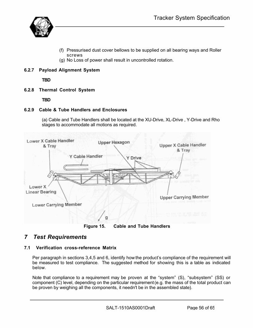
Tracker System Specification
SALT-1510AS0001Draft Page 56 of 65
(f) Pressurised dust cover bellows to be supplied on all bearing ways and Rollerscrews
(g) No Loss of power shall result in uncontrolled rotation.
6.2.7 Payload Alignment System
TBD
6.2.8 Thermal Control System
TBD
6.2.9 Cable & Tube Handlers and Enclosures
(a) Cable and Tube Handlers shall be located at the XU-Drive, XL-Drive , Y-Drive and Rhostages to accommodate all motions as required.
Figure 15. Cable and Tube Handlers
7 Test Requirements
7.1 Verification cross-reference Matrix
Per paragraph in sections 3,4,5 and 6, identify how the product’s compliance of the requirement willbe measured to test compliance. The suggested method for showing this is a table as indicatedbelow.
Note that compliance to a requirement may be proven at the “system” (S), “subsystem” (SS) orcomponent (C) level, depending on the particular requirement (e.g. the mass of the total product canbe proven by weighing all the components, it needn't be in the assembled state).

Tracker System Specification
SALT-1510AS0001Draft Page 57 of 65
The "Test Method" may be any one of the following:_ Review (R) - the design is reviewed and it is obvious to all whether or not the item complies
(e.g. whether or not the system has a particular mode)._ Inspection (I) - the completed item is inspected and compliance can be easily observed. This
is normally used for physical characteristics such as colour, dimensions and mass._ Testing (T) - this entails a technical effort whereby the system is stimulated in a certain
fashion and its response compared to the required response._ Analysis (A) – compliance of the design to the requirement is proved by mathematical
analysis.Where it is considered important, reference to the detail of the test method should be provided in the"Details" column of the table.
Table 25 Verification cross-reference Matrix (TBD21)Para. Requirement Test
MethodTestLevel
Test DetailRef.
e.g.4.14.24.3.1.14.3.1.2
Product Schematic DiagramProductPositioning accuracyNatural frequency
II & TTA
SSSSSS & SS
5.2.1
7.2 Detailed Test Methods
(TBD22)
8 Notes
NA

Tracker System Specification
SALT-1510AS0001Draft Page 58 of 65
APPENDIX A: FUNCTIONAL DEFINITION TABLES
Timeline Diagrams
This table illustrates Closed Loop Guidance.
No Action Start Time Frequency Remarks1. Star position input by RA,
single position or scheduledpositions – on TCS terminal
Acquisition time– 3 minutesminimum
Once per target Star position:RA,DEC,EpochTime
2. Acquisition and Tracking starttimes and ObservationDuration for each target –input by RA on TCS terminal
Acquisition time– 3 minutesminimum
Once per target Time availablebetweenAcquisition andTrack must bevariable by RA
3. TCS send Acquisition andtracking start times andposition to Tracker computer
Acquisition time– 2.5 minutesminimum
Once per target
4. Tracker and Payload slewedto position in 3
Immediately after3.
5. Tracker computer reports toTCS when in position
Acquisition Time– 30 seconds
Once per target
6. TCS send trajectorycommands(x,y,z,q,f,r) toTracker Computer
Immediately after5.
Once every 30sec
Open loopcommands
7. Tracker executes commandsin 6.
According totime stamp ofcommands
Continuously (atsamplingfrequency of axes controllers)
Controllersshouldinterpolatecommandsbetweentrajectory points
8. Target and Guid Starsselected by RA – on TCSterminal
Any timebetweenAcquisition andtrack start time
Once per target
9 Payload Computer sendscorrection signals to Trackercomputer (x,y corrections)
When locked onguid star/s
1Hz
10. Beyond track start time –closed loop tracking, if nocorrection signals frompayload – open loop tracking
Start of Track Continuously (atsamplingfrequency of axes controllers)
Controllersshouldinterpolatecommands
Tabel 3.1.1.1a : Tracker & Payload Timeline for Closed Loop Guidance
This table illustrates Open Loop Guidance.
No Action Start Time Frequency Remarks

Tracker System Specification
SALT-1510AS0001Draft Page 59 of 65
1. Star position input by RA,single position or scheduledpositions – on TCS terminal
Acquisition time– 3 minutesminimum
Once per target Star position:RA,DEC,EpochTime
2. Sidereal Rate selected by RA Acquisition time– 3 minutesminimum
Any time RA can adjustsidereal rate
3. Acquisition and Tracking starttimes and ObservationDuration for each target –input by RA on TCS terminal
Acquisition time– 3 minutesminimum
Once per target Time availablebetweenAcquisition andTrack must bevariable by RA
4. TCS send Acquisition andtracking start times andposition to Tracker computer
Acquisition time– 2.5 minutesminimum
Once per target
5. Tracker and Payload slewedto position in 3
Immediately after3.
6. Tracker computer reports toTCS when in position
Acquisition Time– 30 seconds
Once per target
7. TCS send trajectorycommands(x,y,z,q,f,r) toTracker Computer
Immediately after5.
Once every 30sec
Open loopcommands
8. Tracker executes commandsin 6.
According totime stamp ofcommands
Continuously (atsamplingfrequency of axes controllers)
Controllersshouldinterpolatecommandsbetweentrajectory points
Tabel 3.1.1.1b : Tracker & Payload Timeline for Open Loop Guidance
The next table illustrates Positioning.
No Action Start Time Frequency Remarks1. Star position or Tracker
Position input by RA – onTCS or Tracker Computerterminal
Any time Continuously
2. Tracker and Payload slewedto position in 3
Immediately after1.
6. Tracker computer reports toTCS when in position
When positionreached
Once per target
Tabel 3.1.1.1c : Tracker & Payload Timeline for Positioning
The following timeline tables are for the detailed functions in Figure 7 the first of which is the TrackerComputer functions.
No Action Start Time Frequency
Remarks
1 COMMUNICATION

Tracker System Specification
SALT-1510AS0001Draft Page 60 of 65
1.1 ETHERNET1.1.1 TCS Comms1.1.1.1 TCS -> Tracker Computer :
Command message to Tracker ,thermal control set points,Acquisition offset
When switched on 10Hz The userinterface onTrackercomputer andTCS identical
1.1.1.2 Tracker Computer -> TCS :Reporting Tracker Modes, States,Health status of subsystems,Safety
When switched on 10Hz Status Message
1.1.1.3 Tracker Computer -> TCS :Reporting tracker position, errors,(x,y,z,q,f,r), hexapod positions,collimator errors and thermalcontrol variables
When switched on 10Hz Data Message
1.1.2 Payload Computer Comms1.1.2.1 Payload Computer -> Tracker
ComputerWhen switched on 1Hz Guidance Errors
1.1.3 Axes Controllers Comms1.1.3.1 Axes Control -> Tracker Computer When switched on 10Hz All sensor
readings1.1.3.2 Tracker Computer -> Axes
Controllers : Control loop and modecommands
From when PowerUp Mode entered
1 to10Hz
Variable(toadjust ifaccuracyrequires)
1.2 RS4851.2.1 Payload Alignment Comms1.2.1.1 Payload Alignment Sensors ->
Tracker ComputerWhen switched on 10Hz
1.2.1.2 Tracker Computer -> PayloadAlignment Sensors
When switched on Asrequired
For Setup,calibration
1.2.2 Thermal Control Comms1.2.2.1 Thermal Control -> Tracker
Computer CommsWhen switched on 1Hz Read
Temperaturesensors & ValvePosition
1.2.2.2 Tracker Computer -> ThermalControl Comms
When switched on 1Hz Valve Commands
1.2.3 Power Switches Comms1.2.3.1 Tracker Computer ->Power
Switches CommsDuring Powerup/Shut Down
1.2.4 Gravity Compensation Comms1.2.4.1 Gravity Compensation -> Tracker
Computer Comms : Valve Position &Pressure
When switched on 1Hz ReadTemperaturesensors & ValvePosition

Tracker System Specification
SALT-1510AS0001Draft Page 61 of 65
Position1.2.4.2 Tracker Computer -> Gravity
Compensation: Valve CommandWhen switched on 1Hz Valve Commands
1.3 OTHER1.3.1 Time Sync Input1.3.1.1 Time sync -> Tracker Computer When switched on 1Hz Time sync is part
of TCS
2 TRACKER ALGORITHMS2.1 Power Up MMI Activated NA2.2 Shutdown MMI Activated NA2.3 Time Synchronisation When switched on 1Hz2.4 Tracker Mount Model Entering Power UP
Mode10Hz
2.5 Guidance Corrections MMI Enabled 1Hz Part of Softwareset up
2.6 Axes Command Generator Entering Power UPMode
10Hz
2.7 Orthogonality Corrections Entering StandbyMode
10Hz
2.8 Thermal loop MMI Activated 1Hz2.9 Mode & State Control Switched on 10Hz2.10 Diagnostics & Safety Switched on 10Hz2.11 Software Setup & Maintenance MMI Activated (In
Power up/Shutdown)
NA Save andretrieveconfigurationsetup & data
3 TRACKER MMI3.1 Update MMI When switched on 10Hz
Tabel 3.1.1.1d : Timeline for functions in Tracker Computer
The next table illustrates Axes Control.
No Action Start Time Frequency
Remarks
4 AXES CONTROL4.1 Axes Controllers4.1.1 Receive commands from Tracker
ComputerFrom when PowerUp Mode entered
1to10Hz
Variable – toadjust if required
4.1.2 Read sensor inputs When switched on 100Hz4.1.3 Calculate and Output Servo Amp
CommandsFrom when PowerUp Mode entered
100Hz
4.1.4 Send time stamped sensorreadings to Tracker computer
When switched on 10Hz
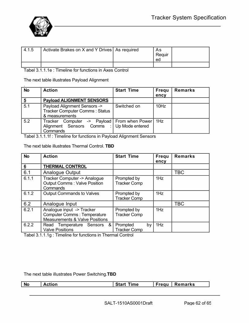
Tracker System Specification
SALT-1510AS0001Draft Page 62 of 65
4.1.5 Activate Brakes on X and Y Drives As required AsRequired
Tabel 3.1.1.1e : Timeline for functions in Axes Control
The next table illustrates Payload Alignment.No Action Start Time Frequ
encyRemarks
5 Payload ALIGNMENT SENSORS5.1 Payload Alignment Sensors ->
Tracker Computer Comms : Status& measurements
Switched on 10Hz
5.2 Tracker Computer -> PayloadAlignment Sensors Comms :Commands
From when PowerUp Mode entered
1Hz
Tabel 3.1.1.1f : Timeline for functions in Payload Alignment Sensors
The next table illustrates Thermal Control. TBD
No Action Start Time Frequency
Remarks
6 THERMAL CONTROL6.1 Analogue Output TBC6.1.1 Tracker Computer -> Analogue
Output Comms : Valve PositionCommands
Prompted byTracker Comp
1Hz
6.1.2 Output Commands to Valves Prompted byTracker Comp
1Hz
6.2 Analogue Input TBC6.2.1 Analogue input -> Tracker
Computer Comms : TemperatureMeasurements & Valve Positions
Prompted byTracker Comp
1Hz
6.2.2 Read Temperature Sensors &Valve Positions
Prompted byTracker Comp
1Hz
Tabel 3.1.1.1g : Timeline for functions in Thermal Control
The next table illustrates Power Switching.TBD
No Action Start Time Frequency
Remarks
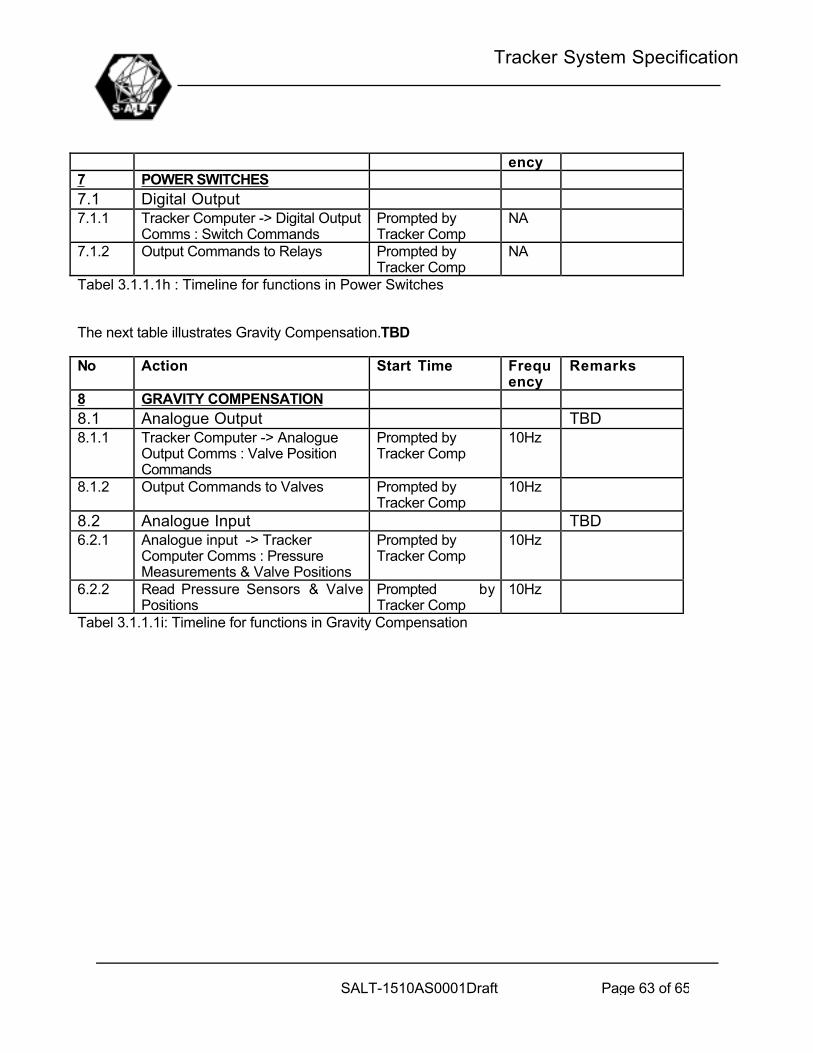
Tracker System Specification
SALT-1510AS0001Draft Page 63 of 65
ency7 POWER SWITCHES7.1 Digital Output7.1.1 Tracker Computer -> Digital Output
Comms : Switch CommandsPrompted byTracker Comp
NA
7.1.2 Output Commands to Relays Prompted byTracker Comp
NA
Tabel 3.1.1.1h : Timeline for functions in Power Switches
The next table illustrates Gravity Compensation.TBD
No Action Start Time Frequency
Remarks
8 GRAVITY COMPENSATION8.1 Analogue Output TBD8.1.1 Tracker Computer -> Analogue
Output Comms : Valve PositionCommands
Prompted byTracker Comp
10Hz
8.1.2 Output Commands to Valves Prompted byTracker Comp
10Hz
8.2 Analogue Input TBD6.2.1 Analogue input -> Tracker
Computer Comms : PressureMeasurements & Valve Positions
Prompted byTracker Comp
10Hz
6.2.2 Read Pressure Sensors & ValvePositions
Prompted byTracker Comp
10Hz
Tabel 3.1.1.1i: Timeline for functions in Gravity Compensation

Tracker System Specification
SALT-1510AS0001Draft Page 64 of 65
APPENDIX D: LIST OF TBD’S AND TBC’S
TBC PARA DESCRIPTION/DATETBC1 2 All reference documents to be finalised by Dec 2001TBC2 4.3.3.1 Trajectory command time steps are to be determined by October 2000TBC3 4.3.3.1 Safety Commands - details by January 2001TBC4 4.3.3.2 Guidance Update rate selected by October 2000TBC5 4.3.3.3 Axes command time steps are to be determined by October 2000TBC6 4.3.3.4 Payload Alignment update Rate is to be determined by October 2000TBC7 4.3.3.6 Power Switch Allocation - October 2000TBC8 4.3.3.7 Time Synch Accuracy: Tracker Computer and TCS - October 2000TBC9 5.3.1.4 Accuracy requirements - October 2000TBC10 5.3.1.8 Tracker Structural Frequencies - November 2000TBC11 5.3.1.9 Max Structural Deflections - November 2000TBC12 5.3.1.9 Action Point of Wind forces - November 2000TBC13 5.3.1.11 Orthogonality requirements - October 2000TBC14 5.3.1.12 Definition of rotation point of Payload - September 2000TBC15 5.3.2.2 Total Tracker Mass - September 2000TBC16 5.3.2.2 Total Payload Mass - September 2000TBC17 5.3.3.1 Max and Min Wind velocities affecting Tracker - October 2000TBC18 5.3.3.2 % Degradation in Marginal Environment - October 2000TBC19 6.1 Payload Alignment Sensor Details - November 2000TBC20 5.3.2.4 Maximum and Minimum Surface Temperatures - November 2000TBC21 5.3.3.1 Maximum nightly temperature range - November 2000TBC22 5.4.4.1.1 Tracker Reliability (% Downtime) - October 2000TBC23 5.4.4.2 No of Toolsets required for maintenance - October 2000TBC24 4.3.3.6 Gravity Compensation is to be determined by October 2000
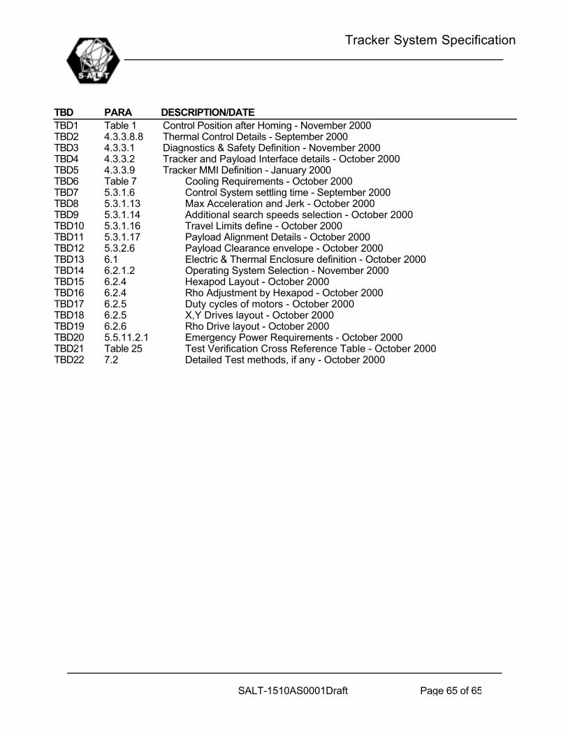
Tracker System Specification
SALT-1510AS0001Draft Page 65 of 65
TBD PARA DESCRIPTION/DATETBD1 Table 1 Control Position after Homing - November 2000TBD2 4.3.3.8.8 Thermal Control Details - September 2000TBD3 4.3.3.1 Diagnostics & Safety Definition - November 2000TBD4 4.3.3.2 Tracker and Payload Interface details - October 2000TBD5 4.3.3.9 Tracker MMI Definition - January 2000TBD6 Table 7 Cooling Requirements - October 2000TBD7 5.3.1.6 Control System settling time - September 2000TBD8 5.3.1.13 Max Acceleration and Jerk - October 2000TBD9 5.3.1.14 Additional search speeds selection - October 2000TBD10 5.3.1.16 Travel Limits define - October 2000TBD11 5.3.1.17 Payload Alignment Details - October 2000TBD12 5.3.2.6 Payload Clearance envelope - October 2000TBD13 6.1 Electric & Thermal Enclosure definition - October 2000TBD14 6.2.1.2 Operating System Selection - November 2000TBD15 6.2.4 Hexapod Layout - October 2000TBD16 6.2.4 Rho Adjustment by Hexapod - October 2000TBD17 6.2.5 Duty cycles of motors - October 2000TBD18 6.2.5 X,Y Drives layout - October 2000TBD19 6.2.6 Rho Drive layout - October 2000TBD20 5.5.11.2.1 Emergency Power Requirements - October 2000TBD21 Table 25 Test Verification Cross Reference Table - October 2000TBD22 7.2 Detailed Test methods, if any - October 2000