tpm - servotechnica.ru · the tpm/tpma can be mounted from either the front or the rear of the...
TRANSCRIPT

TPMServo actuators - Setting newstandards in dynamics, precisionand compactness
New
3-Stage High Torque model TPMA 025-110

6
10

Inde
xOverview WITTENSTEIN group 4 - 5
TPM product features, applications 6 - 9
Design properties & features
TPM series 004 - 110 10 - 29
Technical data, characteristic curves and drawings
TPMA series 025 - 110 30 - 41
Technical data, characteristic curves and drawings
Options and accessories 42 - 44
Brake, temperature sensors, feedback systems, cables
Servo controllers, plug connections 45 - 46
Ordering codes 47

Page
4
Overview - WITTENSTEIN group
Ove
rvie
w
WITTENSTEINcyber motor GmbH
Development and distribution ofmini AC servomotors for industrialapplications.Characteristics: Highest powerdensity and reliability.
WITTENSTEIN AGThe WITTENSTEIN AG , with its 750 employees worldwide, develops, produces and distributeshigh-precision planetary gears, entire electro-mechanical drive systems, as well as AC servo systemsand motors, amongst other products. Areas of application include industrial robots, machine toolsand packaging machines, paper and printing machines, elevators, the Formula 1, as well as the aero-space industry.Technological competence and ongoing innovation ensure the success of the WITTENSTEINAG . Creative and motivated employees are the basis of the company's acclaim. In the past two fis-cal years, more than 200 new employees have joined the company. The turnover yielded by prod-ucts that are less than 5 years old amounts to approx. 85 percent. Every tenth Euro is invested inresearch and development, more than 12 percent of the employees work in these fields.
WITTENSTEINmotion control GmbH
Integrated electro-mechanical,rotative and linear servo systems.Intelligent units with the highestprecision and dynamics.
alpha getr iebebau GmbH
Low-backlash servo gears, plane-tary windlasses with integratedservo drives, as well as the servodesign software cymex®.
Technical solutions: Customer benefit in the foreground

Ove
rvie
w
WITTENSTEINaerospace & simulation GmbH
Development, manufacture, salesand distribution of electro-mechanical control systems, activecontrol units for aeronautical appli-cations and haptic systems withforce feedback for simulators.
Page
5
WITTENSTEINbastian GmbH
Development, manufacture, salesand distribution of innovative geartechnology.Implemented in, for example, theFormula 1 and the aerospaceindustry.
WITTENSTEINintens GmbH
Development, manufacture, saleand distribution of intelligent,innovative implants for orthopedicand accident surgery.
Company premises in Igersheim/Harthausen: Inspiration for innovation 750 motivated employees: Enthusiasm and emotion

Product features
Page
6Pr
oduc
t fe
atur
es
With the TPM and TPMA AC servo actuators, the WITTENSTEIN motion control GmbH is providing the drivetechnology market with products that set new standards in precision, dynamics, power density and compactness.
Rotatable connectors
Brushless AC servo motor
Low-backlash precision planetarygearhead
Optional permanentmagnet holding brake
Resolver feedback is standard. Optional single- or multi-turn absolute feedbacks with EnDat® (Heidenhain) orHiperface® (Stegmann) interfaces available.
TPM 004
TPM 010
up to 40 Nm
up to 100 Nm
TPM 025 up to 300 Nm
TPMA 025 up to 480 Nm
TPM 050 up to 650 Nm
TPMA 050 up to 950 Nm
TPM 110 up to 1600 Nm
TPMA 110 up to 2600 Nm
High Torque
High Torque
High Torque
Torque
overview

Prod
uct
feat
ures
Page
7
Product features
High dynamic performanceAn integral brushless AC servomotor was designed to work with the alpha planetary gearheads to provide a hightorque-to-inertia ratio, optimized for high dynamic performance. Connecting the motor to the gearhead without acoupling improves the stiffness of the unit while reducing the moment of inertia by approximately 40% comparedto customary motor/gearhead units.
High power densityA high pole count motor optimizes use of the magnetic material and yields the most power in the smallest package.In the new 3-stage TPMA version, the torque range has been considerably extended while maintaining the samecompact design.
Compact design/reduced weightIntegrating the servomotor and gearhead into one package sets new standards for reduced size and weight. It isapproximately 62% shorter and weights much less than a traditional motor/gearhead combination of comparablepower. This is especially important for applications where mounting space is limited or where the motor itself is partof the moving load, e.g. robotics and gantries.
High positioning accuracy/efficiencyDirectly mounting the drive elements to the output flange reduces overall size and provides high torsional rigidityand short settling times. The pinion is integrated directly into the motor shaft, resulting in a much shorter motor-to-pinion distance. This design results in much higher positioning accuracy - <1 arc minute of backlash - and higherdynamics, for shorter cycle times and reduced production costs for the customer application. In addition, theTPM/TPMA feature overall efficiency >85%.
Direct mount/reduced componentsThe TPM/TPMA can be mounted from either the front or the rear of the mounting flange. The application loadmounts direcly to the driving flange, eliminating the need for a coupling. Dual tapered roller bearings in the outputstage (from size 050) eliminate the need for additional support bearings in the customer application. In addition, twoswiveling connectors allow for easy cable routing.
Maintenance freeHigh quality synthetic lubricants provide lubrication for the service life of the product.
Smooth motion and quiet operationThe TPMs are characterized by low torque ripple for extremely smooth operation. They feature low noise levels ofless then 65 dB(A).
Simple integrationThe TPM can be operated with most of the brushless servo controllers on the market. Preassembled cables and con-troller-specific start-up instructions simplify installation and start-up.
Optional absolute feedbackAn optional single- or multi-turn absolute encoder eliminates the necessity for homing on start-up.

Page
8
Appl icat ions
App
licat
ions
Six TPM drives on two swivel axes and one rotating axis control an X-ray testing system for cast parts. A move toa new position and an X-ray inspection occur within one second, repeating up to 300 times per part. The rapid posi-tioning and testing procedure requires short settling times, which are achieved because of the low weight, high tor-sional rigidity and low inertia of the TPM drives.
A winding unit without dancer roll forms the terminating unit of an extrusion machine for 2-5 mm wide plastic strips. Constant tension is required for smooth winding of the stripes. The high torsional rigidityand excellent dynamics of the TPM drive enables rapid torque regulation, within an torque-adjustment rangeof 1:40.
Unicor
Yxlon

Page
9
Appl icat ions
App
licat
ions
Three TPM drives control the movement of the three axes of this fastpick and place robot, with up to 120 pick and place cycles per minute.The TPM was chosen for this application because of its high dynamicperformance, low weight, small overall length and high reliability.
Installed in a plant for dosing liquid products, three TPMdrives control the piston dosing pump, a rotary valve andthe container-lifting device. Because of its compact design,three TPM drives are incorporated into a 50 cm x 50 cm x75 cm space.
SIG Robotics
Gasti

Page
10
TPM 004 - Technical data, character ist ic curves and drawings
TPM
004
- T
echn
ical
dat
a
Gearhead data
T2B
T2Not
T2N
n1Max
n1N
jt
Ct21
F2AMax
M2TiltMax
C2K
T012
JGear
Nm
Nm
Nm
min-1
min-1
arcmin
Nm/arcmin
N
Nm
Nm/arcmin
Nm
kgcm2
i = 31
i = 21, 61, 91
i = 31
i = 21, 61, 91
Standard
Reduced
i = 31
i = 91
i = 21
i = 31
i = 61
i = 91
40
32
100
25
15
7,000
6,000
≤ 5
≤ 3
6.8
1,630
91
85
0.15
0.08
0.01
0.01
0.001
0.001
21, 31, 61, 91
Motor data
DC bus voltage
Peak torque 6)
Continuous stall torque
Nominal torque
Peak current 6)
Nominal current
No-load speed 6)
Nominal speed 6)
Max. power
Moment of inertia with resolver
UD
MMax
M0
MN
IMax
INn0
nN
PMax
JMot.
VDC
Nm
Nm
Nm
A
A
min-1
min-1
kW
kgcm2
320
1.70
0.58
0.48
4.20
1.30
9,100
7,625
0.92
0.16
320
0.79
0.31
0.25
2.90
1.00
13,500
11,100
0.58
0.09
i = 21, 31 i = 61, 91
Max. acceleration torque 1)
Emergency Stop torque 2)
Nominal output torque
Max. input speed
Nominal input speed 3)
Torsional backlash
Torsional rigidity
Max. axial force 4)
Max. tilting torque
Tilting rigidity
No-load running torque (n1 = 3000 min-1) 5)
Moment of inertia reflected to the input
General data
Protection class
Permissible transmission temperature
Mounting position
Lubrication
Paint
Noise level (n1 = 3000 min-1)
Weight without/with brake
Direction of rotation
Insulation class
°C
dB(A)
kg
IP64
-10 to +90
Any
Synthetic oil, ISO VG 220
RAL 5002 (Blue)
≤ 65
2.6/3.0 at i = 21/31 2.4/2.7 at i = 61/91
motor and gearhead in same direction
F
1) 1000 cycles per hour2) Permissible 1000 times during the life span of the gearhead
3) At 20°C ambient temperature4) Based on the flange center
5) At 20°C gearhead temperature6) Limit motor values to maximum values of the gearhead
Ratio i

Page
11
TMP
004
- C
hara
cter
isti
c cu
rves
i = 21
i = 31
i = 61
i = 91
The maximum and nominal values of the gearhead can limit the output values in some circumstances.To
rque
T2
[Nm
]
Speed n2 [1/min]
Torq
ue T
2[N
m]
Speed n2 [1/min]
Torq
ue T
2[N
m]
Speed n2 [1/min]
Torq
ue T
2[N
m]
Speed n2 [1/min]
Max. output torque 320V DC
Max. output torque 600V DC
Nominal torque 320V DC
Nominal torque 600V DC
Holding torque: brake
Nominal point 320V DC
Page
12
TPM
004
- D
raw
ings
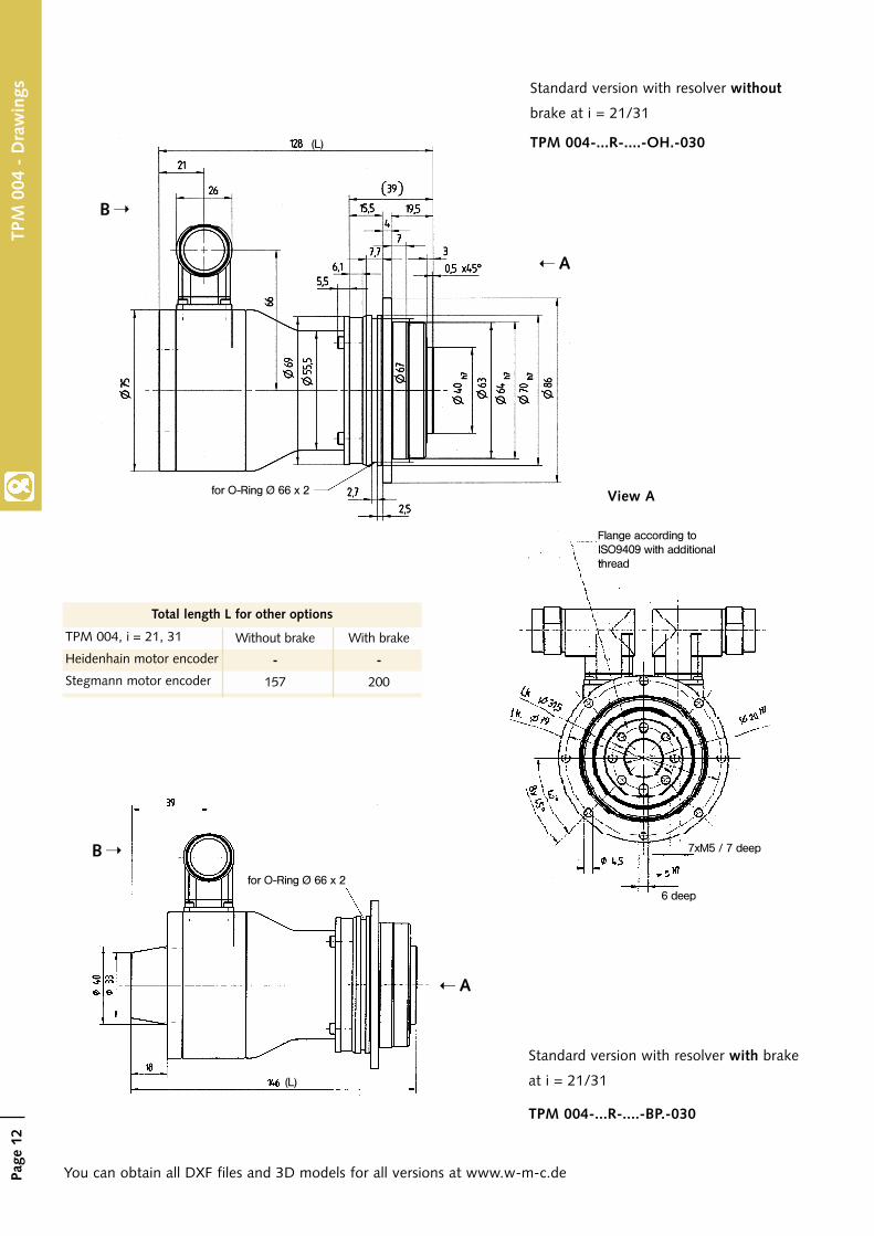
TPM 004-...R-....-OH.-030
View Afor O-Ring Ø 66 x 2
Flange according toISO9409 with additionalthread
7xM5 / 7 deep
6 deep
Standard version with resolver without
brake at i = 21/31
You can obtain all DXF files and 3D models for all versions at www.w-m-c.de
Without brake
-
157
With brake
-
200
TPM 004, i = 21, 31
Heidenhain motor encoder
Stegmann motor encoder
Total length L for other options
A
B
A
B
(L)
TPM 004-...R-....-BP.-030
Standard version with resolver with brake
at i = 21/31(L)
for O-Ring Ø 66 x 2

Page
13
TPM
004
- D
raw
ings
View BFlange according toISO9409 with additionalthread
for O-Ring Ø 66 x 2
Power connector (rotatable)
Signal connector(rotatable)
for O-Ring Ø 66 x 2
Standard version with resolver without
brake at i = 61/91
Without brake
-
142
With brake
-
185
TPM 004, i = 61, 91
Heidenhain motor encoder
Stegmann motor encoder
A
B
A
B
Flange according toISO9409 with additionalthread
(L)
(L)
TPM 004-...R-....-OH.-015
Standard version with resolver with
brake at i = 61/91
TPM 004-...R-....-BP.-015
Total length L for other options

Page
14
TPM 010 - Technical data, character ist ic curves and drawings
TPM
010
- T
echn
ical
dat
a
Gearhead data
T2B
T2Not
T2N
n1Max
n1N
jt
Ct21
F2AMax
M2TiltMax
C2K
T012
JGear
Nm
Nm
Nm
min-1
min-1
arcmin
Nm/arcmin
N
Nm
Nm/arcmin
Nm
kgcm2
i = 31
i = 21, 61, 91
i = 31
i = 21, 61, 91
Standard
Reduced
i = 31
i = 91
i = 21
i = 31
i = 61
i = 91
100
80
250
50
35
7,000
6,450
≤ 3
≤ 1
21
2,150
235
225
0.3
0.2
0.04
0.03
0.01
0.01
Max. acceleration torque 1)
Emergency Stop torque 2)
Nominal output torque
Max. input speed
Nominal input speed 3)
Torsional backlash
Torsional rigidity
Max. axial force 4)
Max. tilting torque
Tilting rigidity
No-load running torque (n1 = 3000 min-1) 5)
Moment of inertia reflected to the input
Motor data
General dataProtection class
Permissible transmission temperature
Mounting position
Lubrication
Paint
Noise level (n1 = 3000 min-1)
Weight without/with brake
Direction of rotation
Insulation class
°C
dB(A)
kg
IP64
-10 to +90
Any
Synthetic oil, ISO VG 220
RAL 5002 (Blue)
≤ 65
4.9/5.3 at i = 21/31 4.4/4.9 at i = 61/91
motor and gearhead in same direction
F
i = 21, 31 i = 61, 91
DC bus voltage
Peak torque 6)
Continuous stall torque
Nominal torque
Peak current 6)
Nominal current
No-load speed 6)
Nominal speed 6)
Max. power
Moment of inertia with resolver
UD
Mmax
M0
MN
IMax
INn0
nN
PMax
JMot.
VDC
Nm
Nm
Nm
A
A
min-1
min-1
kW
kgcm2
320
3.60
1.10
0.94
7.30
1.50
5,800
4,875
1.22
320
1.70
0.60
0.52
4.50
1.10
7,000
5,900
0.75
600
3.30
1.10
0.84
5.00
1.10
7,800
6,775
1.66
600
1.70
0.60
0.51
3.00
0.70
7,700
6,550
0.85
0.210.37
1) 1000 cycles per hour2) Permissible 1000 times during the life span of the gearhead
3) At 20°C ambient temperature4) Based on the flange center
5) At 20°C gearhead temperature6) Limit motor values to maximum values of the gearhead
21, 31, 61, 91Ratio i

Page
16
TPM
010
- D
raw
ings
View A
for O-Ring Ø 90 x 3
7 deep
6 deep
7xM6 / 10 deepFlange accor-ding to ISO9409with additionalthread
Standard version with resolver without
brake at i = 21/31
You can obtain all DXF files and 3D models for all versions at www.w-m-c.de
A
B
Without brake
206.4
184
With brake
242.4
219.5
TPM 010, i = 21, 31
Heidenhain motor encoder
Stegmann motor encoder
for O-Ring Ø 90 x 3
A
B
Total length L for other options
(L)
TPM010-...R-....-OH.-030
(L)
Standard version with resolver with
brake at i = 21/31
TPM 010-...R-....-BP.-030

Page
17
TPM
010
- D
raw
ings
View B
Signal connector(rotatable)
Power connector(rotatable)
for O-Ring Ø 90 x 3
Standard version with resolver without
brake at i=61/91
Without brake
191
170
With brake
229
204.9
TPM 010, i = 61, 91
Heidenhain motor encoder
Stegmann motor encoder
A
B
A
B
(L)
(L)
TPM010-...R-....-OH.-015
Standard version with resolver with
brake at i=61/91
TPM 010-...R-....-BP.-015
Total length L for other options
for O-Ring Ø 90 x 3

Page
18
TPM
025
- T
echn
ical
Dat
a TPM 025 - Technical data, character ist ic curves and drawings
Gearhead data
T2B
T2Not
T2N
n1Max
n1N
jt
Ct21
F2AMax
M2TiltMax
C2K
T012
JGear
Nm
Nm
Nm
min-1
min-1
arcmin
Nm/arcmin
N
Nm
Nm/arcmin
Nm
kgcm2
i = 31
i = 21, 61, 91
i = 31
i = 21, 61, 91
Standard
reduziert
i = 31
i = 91
i = 21
i = 31
i = 61
i = 91
300
250
625
170
100
6,000
5,900
≤ 3
≤ 1
56
4,150
413
550
0.6
0.3
0.10
0.06
0.01
0.01
Max. acceleration torque 1)
Emergency Stop torque 2)
Nominal output torque
Max. input speed
Nominal input speed 3)
Torsional backlash
Torsional rigidity
Max. axial force 4)
Max. tilting torque
Tilting rigidity
No-load running torque (n1 = 3000 min-1)
Moment of inertia reflected to the input
Motor data
General data
Protection class
Permissible transmission temperature
Mounting position
Lubrication
Paint
Noise level (n1 = 3000 min-1)
Weight without/with brake
Direction of rotation
Insulation class
°C
dB(A)
kg
IP64
-10 to +90
Any
Synthetic oil, ISO VG 220
RAL 5002 (Blue)
≤ 65
9.0/9.8 at i = 21/31 7.6/8.4 at i = 61/91
motor and gearhead in same direction
F
i = 21, 31 i = 61, 91
UD
Mmax
M0
MN
IMax
INn0
nN
PMax
JMot.
VDC
Nm
Nm
Nm
A
A
min-1
min-1
kW
kgcm2
320
11.70
5.00
3.30
25.00
6.00
6,380
5,200
4.04
320
4.20
1.70
1.40
10.80
3.10
7.300
5,625
1.72
600
12.40
5.00
3.40
10.60
3.40
6,000
4,838
4.22
600
4.20
1.70
1.30
7.00
1.80
7,800
6,200
1.85
2.39 0.86
DC bus voltage
Peak torque 6)
Continuous stall torque
Nominal torque
Peak current 6)
Nominal current
No-load speed 6)
Nominal speed 6)
Max. power
Moment of inertia with resolver
1) 1000 cycles per hour2) Permissible 1000 times during the life span of the gearhead
3) At 20°C ambient temperature4) Based on the flange center
5) At 20°C gearhead temperature6) Limit motor values to maximum values of the gearhead
21, 31, 61, 91Ratio i

Page
19
TPM
025
- C
hara
cter
isti
c cu
rves
i = 21
i = 31
i = 61
i = 91
The maximum and nominal values of the gearhead can limit the output values in some circumstances.To
rque
T2
[Nm
]
Speed n2 [1/min]
Torq
ue T
2[N
m]
Speed n2 [1/min]
Torq
ue T
2[N
m]
Speed n2 [1/min]
Torq
ue T
2[N
m]
Speed n2 [1/min]
Max. output torque 320V DC
Max. output torque 600V DC
Nominal torque 320V DC
Nominal torque 600V DC
Holding torque: brake
Nominal point 320V DC
Nominal point 600V DC

Page
20
TPM
025
- D
raw
ings
View A
for O-Ring Ø 114 x 3
12 deep
6 deep
Flange according to ISO9409 withadditional thread
for O-Ring Ø 114 x 3
Standard version with resolver without
brake at i = 21/31
You can obtain all DXF files and 3D models for all versions at www.w-m-c.de
Without brake
227
222.5
With brake
268
251
TPM 025, i = 21, 31
Heidenhain motor encoder
Stegmann motor encoder
A
B
A
B
TPM 025-...R-....-OH.-045
Total length L for other options
(L)
(L)
Standard version with resolver with
brake at i = 21/31
TPM 025-...R-....-BP.-045
Page
21
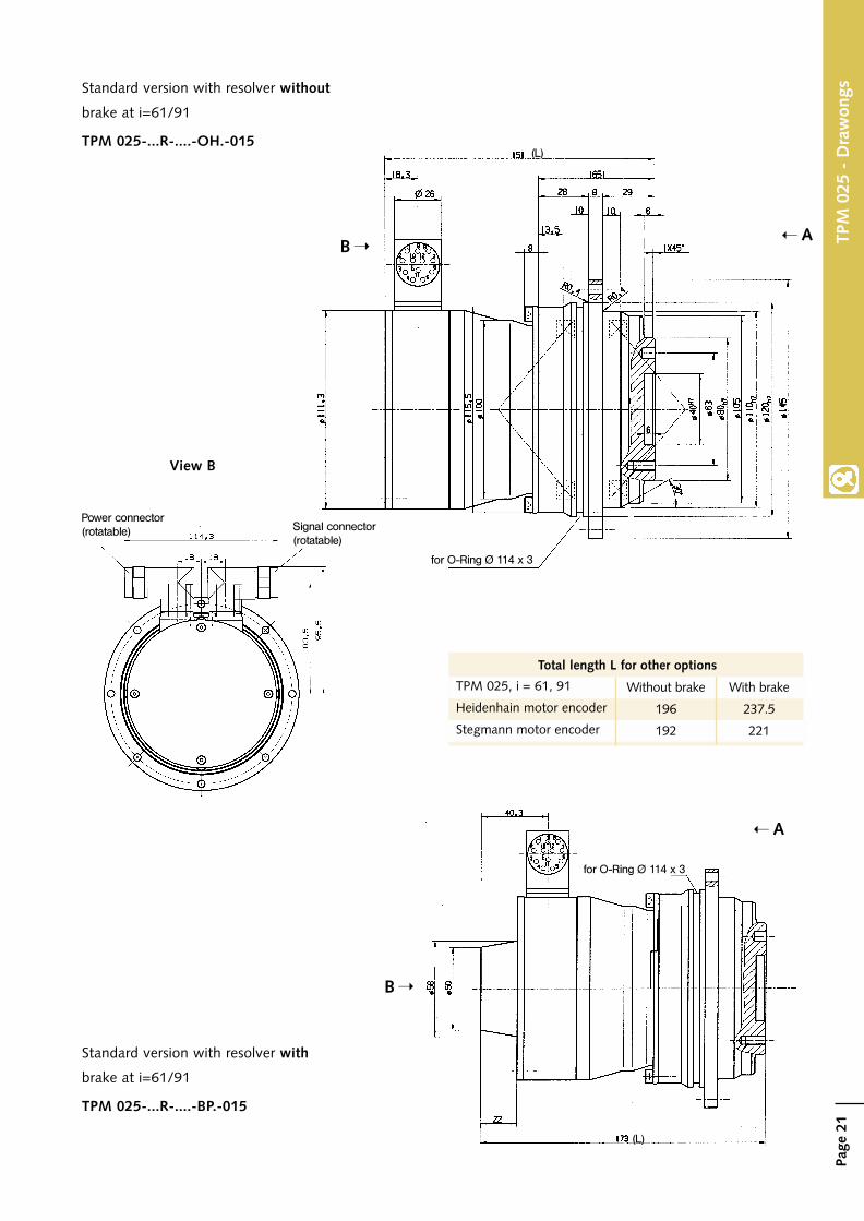
View B
for O-Ring Ø 114 x 3
Standard version with resolver without
brake at i=61/91
Without brake
196
192
With brake
237.5
221
TPM 025, i = 61, 91
Heidenhain motor encoder
Stegmann motor encoder
A
B
AB
Power connector(rotatable) Signal connector
(rotatable)
(L)
(L)
Total length L for other options
TPM 025-...R-....-OH.-015
Standard version with resolver with
brake at i=61/91
TPM 025-...R-....-BP.-015
TPM
025
- D
raw
ongs
for O-Ring Ø 114 x 3
Page
22
TPM
050
- T
echn
ical
Dat
a
TPM 050 - Technical data, character ist ic curves and drawings
Gearhead data
T2B
T2Not
T2N
n1Max
n1N
jt
Ct21
F2AMax
M2TiltMax
C2K
T012
JGear
Nm
Nm
Nm
min-1
min-1
arcmin
Nm/arcmin
N
Nm
Nm/arcmin
Nm
kgcm2
i = 31
i = 21, 61, 91
i = 31
i = 21, 61, 91
Standard
Reduced
i = 31
i = 91
i = 21
i = 31
i = 61
i = 91
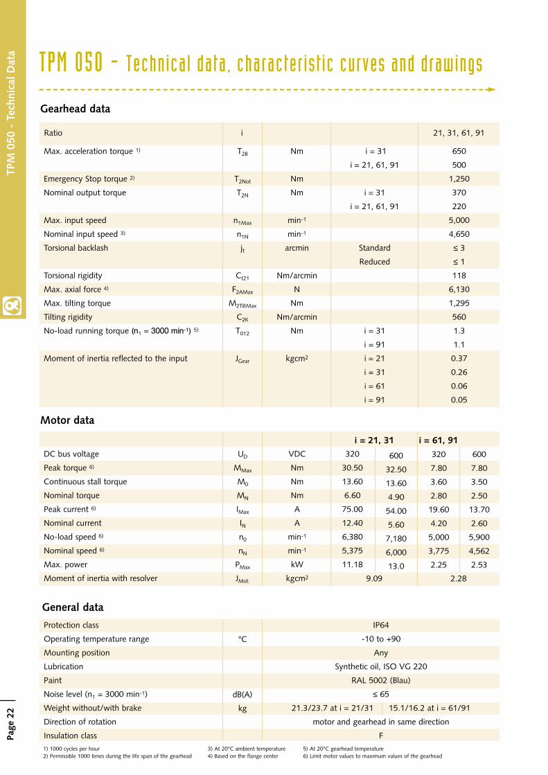
650
500
1,250
370
220
5,000
4,650
≤ 3
≤ 1
118
6,130
1,295
560
1.3
1.1
0.37
0.26
0.06
0.05
Max. acceleration torque 1)
Emergency Stop torque 2)
Nominal output torque
Max. input speed
Nominal input speed 3)
Torsional backlash
Torsional rigidity
Max. axial force 4)
Max. tilting torque
Tilting rigidity
No-load running torque (n1 = 3000 min-1) 5)
Moment of inertia reflected to the input
Motor data
General data
Protection class
Operating temperature range
Mounting position
Lubrication
Paint
Noise level (n1 = 3000 min-1)
Weight without/with brake
Direction of rotation
Insulation class
°C
dB(A)
kg
IP64
-10 to +90
Any
Synthetic oil, ISO VG 220
RAL 5002 (Blau)
≤ 65
21.3/23.7 at i = 21/31 15.1/16.2 at i = 61/91
motor and gearhead in same direction
F
9.09 2.28
i = 21, 31 i = 61, 91
DC bus voltage
Peak torque 6)
Continuous stall torque
Nominal torque
Peak current 6)
Nominal current
No-load speed 6)
Nominal speed 6)
Max. power
Moment of inertia with resolver
UD
MMax
M0
MN
IMax
INn0
nN
PMax
JMot.
VDC
Nm
Nm
Nm
A
A
min-1
min-1
kW
kgcm2
320
30.50
13.60
6.60
75.00
12.40
6,380
5,375
11.18
320
7.80
3.60
2.80
19.60
4.20
5,000
3,775
2.25
600
32.50
13.60
4.90
54.00
5.60
7,180
6,000
13.0
600
7.80
3.50
2.50
13.70
2.60
5,900
4,562
2.53
21, 31, 61, 91Ratio i
1) 1000 cycles per hour2) Permissible 1000 times during the life span of the gearhead
3) At 20°C ambient temperature4) Based on the flange center
5) At 20°C gearhead temperature6) Limit motor values to maximum values of the gearhead

Page
23
TPM
050
- C
hara
cter
isti
c cu
rves
i = 21
i = 31
i = 61
i = 91
The maximum and nominal values of the gearhead can limit the output values in some circumstances.To
rque
T2
[Nm
]
Speed n2 [1/min]
Torq
ue T
2[N
m]
Speed n2 [1/min]
Torq
ue T
2[N
m]
Speed n2 [1/min]
Torq
ue T
2[N
m]
Speed n2 [1/min]
Max. output torque 320V DC
Max. output torque 600V DC
Nominal torque 320V DC
Nominal torque 600V DC
Holding torque: brake
Nominal point 320V DC
Nominal point 600V DC

Page
24
TPM
050
- D
raw
ings
View Afor O-Ring Ø 145 x 3
Flange according to ISO9409with additional thread
7 deep
15 deep
6 deep
for O-Ring Ø 145 x 3
Standard version with resolver without
brake at i = 21/31
You can obtain all DXF files and 3D models for all versions at www.w-m-c.de
Without brake
300
274
With brake
364
346
TPM 050, i = 21, 31
Heidenhain motor encoder
Stegmann motor encoder
AB
A
B
Total length L for other options
TPM 050-...R-....-OH.-060
(L)
(L)
Standard version with resolver with
brake at i = 21/31
TPM 050-...R-...-BP.-060

Page
25
TPM
050
- D
raw
ings
View B
Signal connector(rotatable)
Power connector(rotatable)
for O-Ring Ø 145 x 3
Standard version with resolver without
brake at i=61/91
Without brake
226.5
226.6
With brake
273.5
256.5
TPM 050, i = 61, 91
Heidenhain motor encoder
Stegmann motor encoder
AB
AB
(L)
(L)
Total length L for other options
TPM 050-...R-....-OH.-015
Standard version with resolver with
brake at i=61/91
TPM 050-...R-....-BP.-015
115
114
for O-Ring Ø 145 x 3

Page
26
TPM 110 - Technical data, character ist ic curves and drawings
TPM
110
- T
echn
ical
Dat
a
Gearhead data
T2B
T2Not
T2N
n1Max
n1N
jt
Ct21
F2AMax
M2TiltMax
C2K
T012
JGear
Nm
Nm
Nm
min-1
min-1
arcmin
Nm/arcmin
N
Nm
Nm/arcmin
Nm
kgcm2
i = 31
i = 21 / i = 61, 91
i = 31
i = 61, 91
i = 21
Standard
Reduced
i = 31
i = 91
i = 21
i = 31
i = 61
i = 91
1,600
1,100 / 1,300
2,750
1,230
700
640
4,500
3,500
≤ 3
≤ 1
300
10,050
3,064
1,452
2.8
2.0
1.72
1.16
0.27
0.20
Max. acceleration torque 1)
Emergency Stop torque 2)
Nominal output torque
Max. input speed
Nominal input speed 3)
Torsional backlash
Torsional rigidity
Max. axial force 4)
Max. tilting torque
Tilting rigidity
No-load running torque (n1 = 3000 min-1) 5)
Moment of inertia reflected to the input
Motor data
General dataProtection class
Operating temperature range
Mounting position
Lubrication
Paint
Noise level (n1 = 3000 min-1)
Weight without/with brake
Direction of rotation
Insulation class
°C
dB(A)
kg
IP64
-10 to +90
Any
Synthetic oil, ISO VG 220
RAL 5002 (Blue)
≤ 65
37.1/39.6 at i = 21/31 35.9/38.3 at i = 61/91
motor and gearhead in same direction
F
11.95 9.68
i = 21, 31 i = 61, 91
DC bus voltage
Peak torque 6)
Continuous stall torque
Nominal torque
Peak current 6)
Nominal current
No-load speed 6)
Nominal speed 6)
Max. power
Moment of inertia with resolver
UD
MMax
M0
MN
IMax
INn0
nN
PMax
JMot.
VDC
Nm
Nm
Nm
A
A
min-1
min-1
kW
kgcm2
320
39.60
17.70
12.80
58.00
13.50
3,700
2,875
8.30
320
30.50
13.60
6.60
75.00
12.40
6,380
5,375
11.18
600
39.70
17.80
13.80
26.20
9.70
4,326
3,300
11.30
600
32.60
13.60
4.90
54.00
5.60
7,180
6,000
13.00
21, 31, 61, 91Ratio i
1) 1000 cycles per hour2) Permissible 1000 times during the life span of the gearhead
3) At 20°C ambient temperature4) Based on the flange center
5) At 20°C gearhead temperature6) Limit motor values to maximum values of the gearhead

Page
27
TPM
110
- C
hara
cter
isti
c cu
rves
i = 21
i = 31
i = 61
i = 91
The maximum and nominal values of the gearhead can limit the output values in some circumstances.To
rque
T2
[Nm
]
Speed n2 [1/min]
Torq
ue T
2[N
m]
Speed n2 [1/min]
Torq
ue T
2[N
m]
Speed n2 [1/min]
Torq
ue T
2[N
m]
Speed n2 [1/min]
Max. output torque 320V DC
Max. output torque 600V DC
Nominal torque 320V DC
Nominal torque 600V DC
Holding torque: brake
Nominal point 320V DC
Nominal point 600V DC

Page
28
TPM
110
- D
raw
ings
View Afor O-Ring Ø 200 x 5
Flange according to ISO9409 withadditional thread
20 deep
8 deep
10 d
eep
Standard version with resolver without
brake at i = 21/31
You can obtain all DXF files and 3D models for all versions at www.w-m-c.de
Without brake
326
300
With brake
390
372
TPM 110, i = 21, 31
Heidenhain motor encoder
Stegmann motor encoder
A
B
(L)
Total length L for other options
TPM 110-...R-....-OH.-075
A
B
Standard version with resolver with
brake at i = 21/31
TPM 110-...R-....-BP.-075
for O-Ring Ø 200 x 5
(L)

Page
29
TPM
110
- D
raw
ings
View Bfor O-Ring Ø 200 x 5
Standard version with resolver without
brake at i=61/91
Power connector(rotatable)
Signal connector(rotatable)
Without brake
311
285
With brake
375
357
TPM 110, i = 61, 91
Heidenhain motor encoder
Stegmann motor encoder
A
B
AB
TPM 110-...R-....-OH.-060(L)
(L)
Total length L for other options
Standard version with resolver with
brake at i=61/91
TPM 110-...R-....-BP.-060
for O-Ring Ø 200 x 5

Page
30
TPM
A 0
25 -
Tec
hnic
al d
ata TPMA 025 - Technical data, character ist ic curves and drawings
Gearhead data
T2B
T2Not
T2N
n1Max
n1N
jtCt21
F2AMax
M2TiltMax
C2K
T012
JGear
Nm
Nm
Nm
min-1
min-1
arcmin
Nm/arcmin
N
Nm
Nm/arcmin
Nm
kgcm2 i = 110
i = 220
480
1,200
260
6,000
3,200
≤ 1
97
4,150
413
550
0.4
0.036
0.009
Max. acceleration torque 1)
Emergency Stop torque 2)
Nominal output torque
Max. input speed
Nominal input speed 3)
Torsional backlash
Torsional rigidity
Max. axial force 4)
Max. tilting torque
Tilting rigidity
No-load running torque (n1 = 3000 min-1) 5)
Moment of inertia reflected to the input
Motor data
General data
Protection class
Operating temperature range
Mounting position
Lubrication
Paint
Noise level (n1 = 3000 min-1)
Weight without/with brake
Direction of rotation
Insulation class
°C
dB(A)
kg
IP64
-10 to +90
Any
Synthetic oil, ISO VG 220
RAL 5002 (Blue)
≤ 65
8.4/9.3
motor and gearhead in same direction
F
i = 110, 220
DC bus voltage
Peak torque 6)
Continuous stall torque
Nominal torque
Peak current 6)
Nominal current
No-load speed 6)
Nominal speed 6)
Max. power
Moment of inertia with resolver
UD
MMax
M0
MN
IMax
INn0
nN
PMax
JMot.
VDC
Nm
Nm
Nm
A
A
min-1
min-1
kW
kgcm2
320
4.20
1.70
1.40
10.80
3.10
7,300
5,625
1.72
600
4.20
1.70
1.30
7.00
1.80
7,800
6,200
1.85
0.86
Hig
h To
rque
110, 220Ratio i
1) 1000 cycles per hour2) Permissible 1000 times during the life span of the gearhead
3) At 20°C ambient temperature4) Based on the flange center
5) At 20°C gearhead temperature6) Limit motor values to maximum values of the gearhead

Page
31
TPM
A 0
25 -
Cha
ract
eris
tic
curv
es
i = 110
i = 220
The maximum and nominal values of the gearhead can limit the output values in some circumstances.
Hig
h To
rque
Torq
ue T
2[N
m]
Speed n2 [1/min]
Torq
ue T
2[N
m]
Speed n2 [1/min]
Max. output torque 320V DC
Max. output torque 600V DC
Nominal torque 320V DC
Nominal torque 600V DC
Holding torque: brake
Nominal point 320V DC
Nominal point 600V DC
Page
32
TPM
A 0
25 -
Dra
win
gs
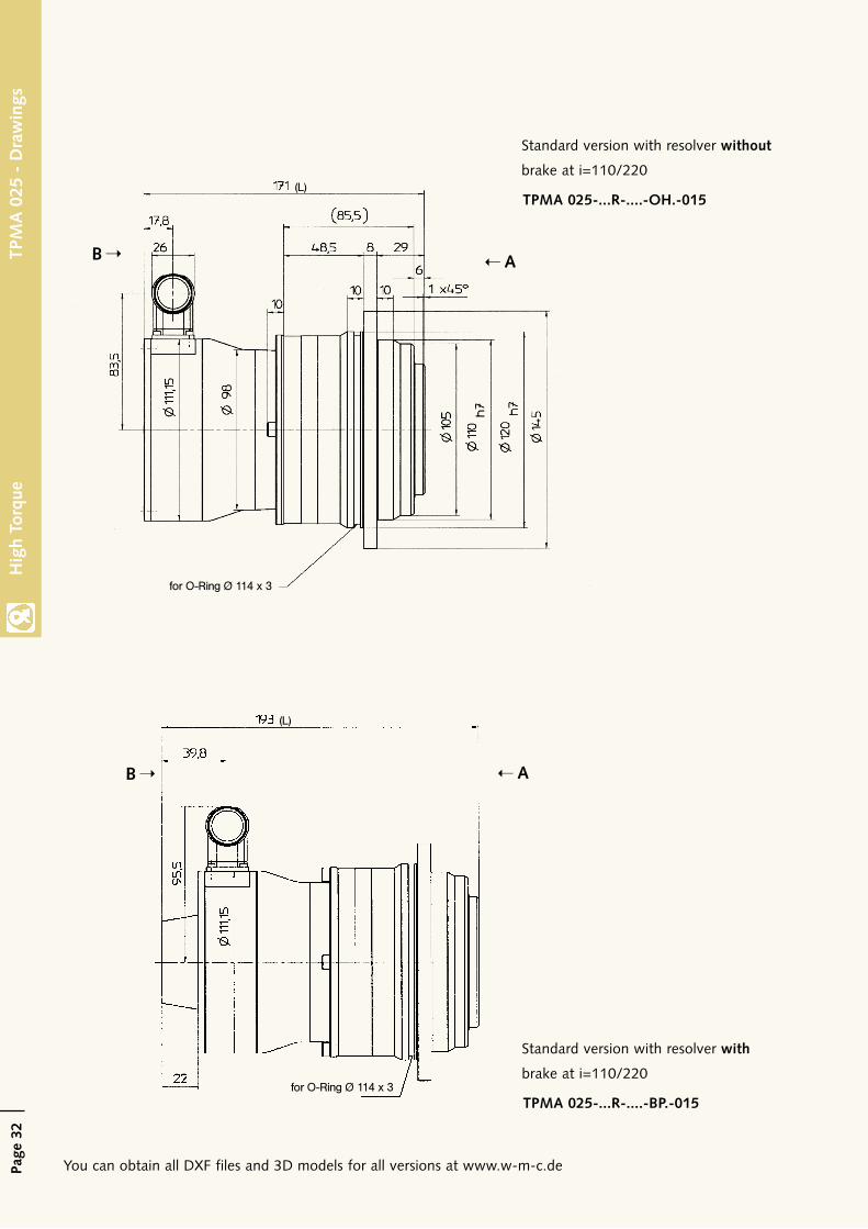
Standard version with resolver without
brake at i=110/220
You can obtain all DXF files and 3D models for all versions at www.w-m-c.de
for O-Ring Ø 114 x 3
AB
AB
TPMA 025-...R-....-OH.-015(L)
(L)
Standard version with resolver with
brake at i=110/220
TPMA 025-...R-....-BP.-015
Hig
h To
rque
for O-Ring Ø 114 x 3

Page
33
TPM
A 0
25 -
Dra
win
gs
6 deep
View A
12 deep
Power connector(rotatable)
Signal connector(rotatable)
View B
Without brake
217
213
With brake
258.6
241.6
TPMA 025, i = 110, 220
Heidenhain motor encoder
Stegmann motor encoder
Total length L for other options
Hig
h To
rque

Page
34
TPMA 050 - Technical data, character ist ic curves and drawings
Gearhead data
T2B
T2Not
T2N
n1Max
n1N
jtCt21
F2AMax
M2TiltMax
C2K
T012
JGear
Nm
Nm
Nm
min-1
min-1
arcmin
Nm/arcmin
N
Nm
Nm/arcmin
Nm
kgcm2 i = 110
i = 220
950
2,375
675
5,000
2,600
≤ 1
186
6,130
1,295
560
0.8
2.43
2.31
Max. acceleration torque 1)
Emergency Stop torque 2)
Nominal output torque
Max. input speed
Nominal input speed 3)
Torsional backlash
Torsional rigidity
Max. axial force 4)
Max. tilting torque
Tilting rigidity
No-load running torque (n1 = 3000 min-1) 5)
Moment of inertia reflected to the input
Motor data
General data
Protection class
Operating temperature range
Mounting position
Lubrication
Paint
Noise level (n1 = 3000 min-1)
Weight without/with brake
Direction of rotation
Insulation class
°C
dB(A)
kg
IP64
-10 to +90
Any
Synthetic oil, ISO VG 220
RAL 5002 (Blue)
≤ 70
17.6/18.8
motor and gearhead in same direction
F
TPM
A 0
50 -
Tec
hnic
al d
ata
i = 110, 220
DC bus voltage
Peak torque 6)
Continuous stall torque
Nominal torque
Peak current 6)
Nominal current
No-load speed 6)
Nominal speed 6)
Max. power
Moment of inertia with resolver
UD
MMax
M0
MN
IMax
INn0
nN
PMax
JMot.
VDC
Nm
Nm
Nm
A
A
min-1
min-1
kW
kgcm2
320
7.80
3.60
2.80
19.60
4.20
5,000
3,775
2.25
600
7.80
3.50
2.50
13.70
2.60
5,900
4,562
2.53
2.28
Hig
h To
rque
110, 220Ratio i
1) 1000 cycles per hour2) Permissible 1000 times during the life span of the gearhead
3) At 20°C ambient temperature4) Based on the flange center
5) At 20°C gearhead temperature6) Limit motor values to maximum values of the gearhead

Page
35
TPM
A 0
50 -
Cha
ract
eris
tic
curv
es
i = 110
i = 220
The maximum and nominal values of the gearhead can limit the output values in some circumstances.
Hig
h To
rque
Torq
ue T
2[N
m]
Speed n2 [1/min]
Torq
ue T
2[N
m]
Speed n2 [1/min]
Max. output torque 320V DC
Max. output torque 600V DC
Nominal torque 320V DC
Nominal torque 600V DC
Holding torque: brake
Nominal point 320V DC
Nominal point 600V DC

Page
36
TPM
A 0
50 -
Dra
win
gs
Standard version with resolver without
brake at i=110/220
You can obtain all DXF files and 3D models for all versions at www.w-m-c.de
for O-Ring Ø 145 x 3
for O-Ring Ø 145 x 3
A
B
AB
TPMA 050-...R-....-OH.-015
(L)
(L)
Standard version with resolver with
brake at i=110/220
TPMA 050-...R-....-OH.-015
Hig
h To
rque

Page
37
TPM
A 0
50 -
Dra
win
gs
View B
View A
Signal connector(rotatable)Power connector
(rotatable)
15 deep
6 deep
Without brake
263
263
With brake
310
292
TPMA 050, i = 110, 220
Heidenhain motor encoder
Stegmann motor encoder
Total length L for other options
Hig
h To
rque

Page
38
TPMA 110 - Technical data, character ist ic curves and drawings
Gearhead data
T2B
T2Not
T2N
n1Max
n1N
jtCt21
F2AMax
M2TiltMax
C2K
T012
JGear
Nm
Nm
Nm
min-1
min-1
arcmin
Nm/arcmin
N
Nm
Nm/arcmin
Nm
kgcm2 i = 110
i = 220
2,600
6,500
1,570
4,500
2,100
≤ 1
550
10,050
3,064
1,452
1.70
0.646
0.159
Max. acceleration torque 1)
Emergency Stop torque 2)
Nominal output torque
Max. input speed
Nominal input speed 3)
Torsional backlash
Torsional rigidity
Max. axial force 4)
Max. tilting torque
Tilting rigidity
No-load running torque (n1 = 3000 min-1) 5)
Moment of inertia reflected to the input
Motor data
General data
Protection class
Operating temperature range
Mounting position
Lubrication
Paint
Noise level (n1 = 3000 min-1)
Weight without/with brake
Direction of rotation
Insulation class
°C
dB(A)
kg
IP64
-10 to +90
Any
Synthetic oil, ISO VG 220
RAL 5002 (Blue)
≤ 70
43.6/46.0
motor and gearhead in same direction
F
TPM
A 1
10 -
Tec
hnic
al d
ata
i = 110, 220
DC bus voltage
Peak torque 6)
Continuous stall torque
Nominal torque
Peak current 6)
Nominal current
No-load speed 6)
Nominal speed 6)
Max. power
Moment of inertia with resolver
UD
MMax
M0
MN
IMax
INn0
nN
PMax
JMot.
VDC
Nm
Nm
Nm
A
A
min-1
min-1
kW
kgcm2
320
30.50
13.60
6.60
75.00
12.40
6,380
5,375
11.18
600
32.60
13.60
4.90
54.00
5.60
7,180
6,000
13.00
9.68
Hig
h To
rque
110, 220Ratio i
1) 1000 cycles per hour2) Permissible 1000 times during the life span of the gearhead
3) At 20°C ambient temperature4) Based on the flange center
5) At 20°C gearhead temperature6) Limit motor values to maximum values of the gearhead

Page
39
TPM
A 1
10 -
Cha
ract
eris
tic
curv
es
i = 110
i = 220
The maximum and nominal values of the gearhead can limit the output values in some circumstances.
Hig
h To
rque
Torq
ue T
2[N
m]
Speed n2 [1/min]
Torq
ue T
2[N
m]
Speed n2 [1/min]
Max. output torque 320V DC
Max. output torque 600V DC
Nominal torque 320V DC
Nominal torque 600V DC
Holding torque: brake
Nominal point 320V DC
Nominal point 600V DC

Page
40
TPM
A 1
10 -
Dra
win
gs
Standard version with resolver without
brake at i=110/220
You can obtain all DXF files and 3D models for all versions at www.w-m-c.de
for O-Ring Ø 200 x 5
for O-Ring Ø 200 x 5
A
B
A
B
TPMA 110-...R-....-OH.-060(L)
(L)Standard version with resolver with
brake at i=110/220
TPMA 110-...R-....-BP.-060
Hig
h To
rque

Page
41
TPM
A 1
10 -
Dra
win
gs
8 deep
19 deep
Power connector(rotatable)
Signal connector(rotatable)
View B
View A
Without brake
356.5
330.5
With brake
420.5
402.5
TPMA 110, i = 110, 220
Heidenhain motor encoder
Stegmann motor encoder
Total length L for other options
Hig
h To
rque

Page
42
Opt ions
Electrically-released holding brakeA compact permanent-magnet brake is available for holding the rotor when the power is off. It is characterized bybacklash-free operation, drag-free when disengaged, unlimited ON time and constant torque at high operating tem-peratures.
Temperature sensorsThe following temperature sensors are available with various servo controllers. They measure temperature directlyat the motor coil.
• PTC - Positive temperature coefficient thermistor• KTY - Linear temperature coefficient thermistor• NTC - Negative temperature coefficient thermistor
Feedback systemsVarious feedback systems are available for position encoding.
A single turn brushless resolver feedback is standard for TPM. This robust feedback device is suitable for many appli-cations with normal demands for smooth running and precision.
For higher technical demands, optical encoders are available from Heidenhain and Stegmann. Using the EnDat® andHiperface® interfaces, position values as well as information regarding startup and drive data can be stored to andretrieved from the TPM.
See page 46 for the respective pin assignments.
Opt
ions
Data
Holding torque at 20°C
Holding torque at 100°C
Dynamic torque
Moment of inertia
Weight
Release/set time
Coil resistance at 20°C
Supply voltage
Current
Nm
Nm
Nm
kgcm2
kg
ms
Ω
V DC
A
TPM 004
1
0.8
0.8
0.021
0.11
12/8
53-62
0.45
TPM 010,TPM(A) 025
2
1.8
1.7
0.068
0.15
25/6
48-56
0.55
TPM(A) 110,TPM 050(i=21/31)
18
15
15
1.66
0.9
50/10
22-26
1.1
24 +6% -10%
TPM 004
only with
resolver
0.4
-
-
0.01
0.05
27/13
96
0.25
TPM(A) 050(i=61/91/110/220)
4.5
4.0
3.8
0.18
0.30
35/7
45-51
0.54

Page
43
Comparison of TPM feedback devices
Com
pari
son
of T
PM f
eedb
ack
devi
ces
HEI
DEN
HA
INST
EGM
AN
N
Para
met
er
Enco
der
type
Ope
ratin
g vo
ltage
Dat
a in
terf
ace
Elec
tron
ic t
ype
plat
e
Form
of
the
incr
emen
tal s
igna
ls
Num
ber
of s
in/c
os p
erio
ds p
er r
evol
utio
n
Ref
eren
ce t
rack
ava
ilabl
e
Abs
olut
e po
sitio
n w
hen
mai
n po
wer
is o
n
Abs
olut
e re
solu
tion
Mul
titur
n fu
nctio
n
Mul
titur
n m
easu
ring
rang
e
Max
. ope
ratin
g te
mpe
ratu
re
Min
. ope
ratin
g te
mpe
ratu
re
Mom
ent
of in
ertia
Uni
t
V
Pos.
/rev
Rev
.
°C °C
10-2kg
cm2
ERN
1387
Incr
emen
tal
5 - - 1 V
ss
2048
(w
ithin
1 r
evol
utio
n)
1 Si
n/C
os p
erio
d
- -
120
-30
2,6
ECN
1313
Abs
. Sin
glet
urn
5
EnD
at
1 V
ss
2048 -
( w
ithin
1 r
evol
utio
n)
8192 - -
115
-30
2,6
EQN
1325
Abs
. Mul
titur
n
5
EnD
at
1 V
ss
2048 -
8192
4096
115
-30
2,6
SRS5
0/66
K
Abs
. Sin
glet
urn
7 ...
12
Hip
erfa
ce
1 V
ss
1024 -
(w
ithin
1 r
evol
utio
n)
3276
8
- -
115
-20 1
Abs
. Sin
glet
urn
7 (1
0 K
Hz)
- - - 1 -
( w
ithin
1 r
evol
utio
n)
1 Si
n/C
os p
erio
d
- -
150
-55
Res
olve
r
TPM
004
0,2
TPM
(A)0
10-0
503
TPM
110
23,4
SRM
50/6
6K
Abs
. Mul
titur
n
7 ...
12
Hip
erfa
ce
1 V
ss
1024 -
3276
8
4096
115
-20 1

Page
44
Accessories
Acc
esso
ries
CablesMatching signal and power cables for the tested servo controllers listed on page 45 are available.
Please supply the following data when you order:
• Complete TPM description• Desired length of cable, in 5 meter increments.• Exact type description of servo controller to be used
The cables have excellent quality:
• Suitable for cable tracks, because highly flexible wires in accordance with DIN VDE 0295, class 6• Oil and fire proof• Free of halogen, silicon and CFC
Mechanical characteristics:
Static 50 N/mm2 conductor diameter
Dynamic 20 N/mm2 conductor diameter
± 30°/m
Static: -50°C to +80°C
Flexed: -20°C to +70°C
10 x D (outer diameter of cable)
)
5 million (at bending radius 10 x D)
5 m/sec2
180 m/min
Max. tensile strength
Max. permissible torsion
Permissible operating temperature
Min. permissible bending radius
Number of bending cycles
Max. permissible acceleration
Max. permissible speed
TPM 004 - TPM(A) 050 (i=61, 91, 110, 220)
TPM 050 (i=21, 31), TPM(A) 110
)
Power cable
Signal cable
D
12,2 mm
15,1 mm
10 mm
conductor diameter
4 x 1,5 mm2 + 2 x 0,75 mm2
4 x 2,5 mm2 + 2 x 1 mm2

Page
45
Servo control ler
Serv
o co
ntro
ller
The TPM/TPMA AC servo actuators can be operated with a wide variety of servo controllers. The subsequent tablelisted all tested controllers with information on the correct option choices, feedbacks, temperature sensor and DCbus voltage.
For a number of these, a written startup manual is available. It contains all relevant parameter settings of the respec-tive manufacturer to ensure that the startup can be performed in the shortest possible time.
Series/typeManufacturer
feedback device Temperature sensor DC bus voltageR
esol
ver
Incr
emen
tal
EnD
atin
terf
ace
Hip
erfa
cein
terf
ace
PTC
NTC
KTY
84-
130
Can
not
beim
plem
ente
d w
ithTP
M ..
.
AMK 2)
Atlas Copco
Berger Lahr 2)
Bosch 2)
B & R 2)
CT 1)
ESR Pollmeier
Hauser Hannifin 2)
Bosch Rexroth
(Indramat) 1)
KEB 1)
Lenze 1)
Nord 2)
Danaher Motion 1)
(Seidel Kollmorgen)
Siemens 1)
S.B.C. 2)
AMKKASYN KU
DMC 2
Twin Line
Servo Dyn D
AcoPos
UniDrive
Trio-/Mididrive Digital
Compax
Ecodrive 03
Ecodrive 03, 16A
DIAX 04
Combivert S4
Global Drive 93xx
SK 1000 E
Servostar 600/400
SimoDrive 611U
SimoDrive 611D/840D
Master Drive MC
HPD
LVD
320V
DC
600V
DC
-
-
-
-
-
-
-
-
-
-
-
-
-
-
-
-
-
-
-
-
-
-
-
-
-
-
-
-
-
-
-
-
-
-
-
-
-
-
-
-
-
-
-
-
-
-
-
-
-
-
-
-
-
-
-
-
-
-
-
-
-
-
-
-
-
-
-
-
-
-
-
-
-
-
-
-
-
-
-
-
-
-
-
-
-
-
004
004
004
004, 010
004, 010
004
004
004
004
004
Information on additional controllers can be supplied on request.
= possible
- = not available
1) = Startup manual available
2) = Startup manual in preparation

Page
46
Plug connect ions
Plug
con
nect
ions
Electrically releasedbrake/optional
Servo motorground
Power connector
2
6
4
1 5
Temperature sensor
Signal connector
Temperature sensor
n.c.
REFCOS+48S
SINREFSIN
-48SCOSGnd
8VShield
Encoder:SRS 050/66KSRM 050/66K
12
3
4 56
78
910
11
12
Resolver
Temperature sensor
cos/S1
Temperature sensor
cos-low/S3sin/S2
sin-low/S4Ref/R1
Ref-low/R2Shield
Temperature sensor
Temperature sensor
Optional 2x NTC
Signal connector
1 92
12 7116
54
3
10 8
Electrically releasedbrake/optional
45
6
Power connector
Temperature sensorKTY84-130/PTCTemperature sensor
Ua1*Ua1
Ua2*Ua2
Data*Data
Cycle
*CycleM-EncoderOV-SenseP-Encoder5V Sense
n.c.n.c.n.c.
21
3
456
78
9
1011
1213
1415
1617
Resolver, Singleturn
Stegmann encoder, Single and MultiturnHiperface®
Heidenhain encoder, Single- and MultiturnEnDat®
12
Temperature sensorKTY84-130Temperature sensor
Ua1*Ua1
Ua2
*Ua2
Ua0*Ua0
Ua4
*Ua4M-Encoder
OV SenseP-Encoder5V Sense
Dig
ital s
ervo
fee
dbac
kE
RN
1387
Signal connector
21
3
4567
8910
1112
13
141516 17
Heidenhain encoder, incremental
Ua3
*Ua3
n.c.
Electrically releasedbrake/optional
45
6
Power connector
12
Electrically releasedbrake/optional
45
6
Power connector
12
Dig
ital s
ervo
fee
dbac
kE
CN
1313
/ E
CN
1325
Temperature sensorTemperature sensor
Optional 2x NTC
Signal connector

Page
47
Order ing codes
Ord
erin
g co
des
SizeTPM 004 / 010 / 025 / 050 / 110TPMA 025 / 050 / 110
Ratio21 / 31 / 61 / 91 (TPM)110 / 220 (TPMA)
Motor encoderR = ResolverS = Singleturn absolute encoder EnDat®
M = Multiturn absolute encoder EnDat®
N = Singleturn absolute encoder Hiperface®
K = Multiturn absolute encoder Hiperface®
I = Incremental encoder
TPM 025 - 021M - 600K - BP1
Backlash1 = Standard < 3 (5) arcmin0 = Reduced < 1 (3) arcmin
(values in brackets: TPM 004)
BrakesBP = Permanent magnet brakeOH = Without brake
Temperature sensorP = PTCN = NTCK = KTY 84-130
DC bus voltage320 = 320V DC at controller input
voltage 1x230V/3x230V AC600 = 600V DC at controller input
voltage 3x400V AC
Additional options without codes• Straight plug connections• Painted in RAL 9005 (black)• Synthetic oil, ISO PG68• UL approbation• Explosionproof model (on request)