towbar installation instructions towbar capacity
TRANSCRIPT

HAYMAN REESE PART No: 03267RW
MITSUBISHI TRITON MR MY19 CL4 UTE
INSTALLATION INSTRUCTIONS
PLEASE ENSURE THAT ALL INSTRUCTIONS ARE UNDERSTOOD PRIOR TO FITMENT PLACE THESE INSTRUCTIONS IN THE VEHICLE’S GLOVEBOX AFTER INSTALLATION IS COMPLETED
Towbar Installation Instructions Towbar capacity
MITSUBISHI TRITON MR MY19 CL4 UTE Part Number 03267RW Max Towing Braked 3100 kg Max Towing Unbraked 750 kg Max Static Ball Load 310 kg
Installation Time: Approx 30 Mins
Hayman Reese (Cequent) PO Box 4050, Dandenong South VIC 3164
Phone 1800 812 017 Email [email protected]

HAYMAN REESE PART No: 03267RW
MITSUBISHI TRITON MR MY19 UTE
INSTALLATION INSTRUCTIONS PLEASE ENSURE THAT ALL INSTRUCTIONS ARE UNDERSTOOD PRIOR TO FITMENT
PLACE THESE INSTRUCTIONS IN THE VEHICLES’S GLOVEBOX AFTER INSTALLATION IS COMPLETED
Rev: C Page 2 Issue Date: 10-10-2019
Warning: 1. Do not, drill, cut, weld or otherwise modify the towbar. 2. If you are using electric welding on a motor vehicle, always check that the vehicle is not equipped with electronic
engine or instrument management equipment. Failure to do so could destroy any onboard computers. If in
doubt, check with the vehicle's manufacturer. 3. If TBM is used in inverted position tow ball may make contact with rear tailgate when lowered, which could cause
damage.
General: 1. Ensure all hardware items have been included refer to assembly diagram. 2. It is recommended that the instructions are read through and completely understood before making any attempt
to fit this product. 3. Be wary of any changes to vehicle designs or other accessories that may conflict with the installation of this
product. 4. Before drilling ensure that the area is clear of fuel, electrical & other components. 5. All holes drilled into the body panels shall have all burrs & swarf removed then coated with a suitable rust
preventative paint. 6. The high tensile fasteners supplied with this product were used to achieve the specified rating. If replacement is
required ensure that fasteners of the same rating & quality are used. Contact an authorised Hayman Reese
dealer if further information is required. 7. Ensure that all hardware is fastened to torque list below check fasteners on regular basis. 8. Towbar load rating sticker provided with this product shall be conspicuously located on inside rear end of the
driver's door. (See diagram below).
9. Hayman Reese recommends that you check your tow ball to ensure that it complies with the Australian standards AS 4177.2.
10. PLEASE NOTE: It is advised to remove your LUG or TBM when not actually towing so as to produce a clear
view of the vehicles registration plate if obscured, and to also provide maximum available departure angle. 11. Pull Pin must be fit in down position.
Tow bar Maintenance and Care.
Hayman Reese recommends that bolt torque’s, as listed below, are routinely and regularly inspected and checked for correct tension. Replace any worn or defective parts. We recommended to remove Tow Ball Mounts (TBM’s, tongues or lugs) when not being used for any considerable length of time. So as to avoid injury, when not towing it is suggested that the tongue, Pull Pin and R-clip are removed then stored in a safe, clean and dry place, away from excessive moisture. Hitch Pull Pins and spring “R” clips are regularly checked for proper installation. Replace any worn or defective parts.
FOR TOWING PURPOSES ONLY For towing capacity details please refer to vehicle owner’s manual or to the manufacturer. Overloading can
void your warranties.
RECOMMENDED ASSEMBLY TORQUE LISTING
Diameter Grade 8.8 Bolt M6 9.5 Nm M8 21.7 Nm M10 43.4 Nm M12 77.3 Nm M14 146 Nm M16 189.8 Nm
Place load rating sticker
inside driver’s door here

HAYMAN REESE PART No: 03267RW
MITSUBISHI TRITON MR MY19 UTE
INSTALLATION INSTRUCTIONS PLEASE ENSURE THAT ALL INSTRUCTIONS ARE UNDERSTOOD PRIOR TO FITMENT
PLACE THESE INSTRUCTIONS IN THE VEHICLES’S GLOVEBOX AFTER INSTALLATION IS COMPLETED
Rev: C Page 3 Issue Date: 10-10-2019
ITEM DESCRIPTION QTY
1 TRITON WITH STEP WELDED ASSY 1
2 CLASS 4 TBM 1
3 WASHER PLAIN 1/2X1-1/8X16G 20
4 M12x1.75 HEX NUT PC8 10
5 SET SCREW M12-1.75x40 GR10.9 10
6 UNIVERSAL PLUG BRACKET KIT 1
7 TOWBALL 50MM FLAT CHROME 3500KG HR 1
8 "D" SHACKLE 10mm 2
9 SMART PIN ASSY CLASS 4 – GOLD 1
10 HAYMAN REESE LOGO STICKER 1
11 HITCH BOX COLLAR COVER 1
12 WIRING LOOM 1
13 ACRYLIC COMPLIANCE LABEL 1
14 M4 WASHER 2
15 SCREW PAN HD M4 X 16 X 0.7P G4.6 2
16 NUT NYLON LOCK HEX HD M4X0.7P G8 2

HAYMAN REESE PART No: 03267RW
MITSUBISHI TRITON MR MY19 UTE
INSTALLATION INSTRUCTIONS PLEASE ENSURE THAT ALL INSTRUCTIONS ARE UNDERSTOOD PRIOR TO FITMENT
PLACE THESE INSTRUCTIONS IN THE VEHICLES’S GLOVEBOX AFTER INSTALLATION IS COMPLETED
Rev: C Page 4 Issue Date: 10-10-2019
1. Remove step from vehicle secured with 2
bolts per side, making sure to disconnect reversing sensors if fitted.
2. Remove LH Step bracket from vehicle secured with 2 x bolts complete with 2 x washers and 1 x nut per bolt and discard. Repeat for other side.
3. Lift towbar to vehicle and secure with 5 x
Bolts complete with 2 x washers and 1 x nut per bolt on both the LH & RH side. Torque all fasteners to 109Nm.

HAYMAN REESE PART No: 03267RW
MITSUBISHI TRITON MR MY19 UTE
INSTALLATION INSTRUCTIONS PLEASE ENSURE THAT ALL INSTRUCTIONS ARE UNDERSTOOD PRIOR TO FITMENT
PLACE THESE INSTRUCTIONS IN THE VEHICLES’S GLOVEBOX AFTER INSTALLATION IS COMPLETED
Rev: C Page 5 Issue Date: 10-10-2019
4. Refit the step to vehicle, using the existing
fasteners, to the towbar sidearms. Torque the fasteners to 50Nm.

Page 1
Wiring Loom Installation Time: Approx. 15 minutes
INSTALLATION INSTRUCTIONS
Hayman Reese (Cequent)
PO Box 4050, Dandenong South VIC 3164
Phone 1800 812 017 Email [email protected]
www.haymanreese.com.au
Wiring Loom Installation Instructions
MITSUBISHI TRITON
Part No: 102148-WL
Tail Harness Length Required: 1200mmECU - N/A
RPA Disable - N/A Electric Brake Input Location: Blue Wire Near Connector
Breakout
HAYMAN REESEPART No: 102148-WLMITSUBISHI TRITON
PLEASE ENSURE THAT INSTRUCTIONS ARE UNDERSTOOD PRIOR TO FITMENT
Part No: 102148-WLIssue Date 01-02-19
1 1
1
1 1
1 1
1 1
Pointers
1
Page 2
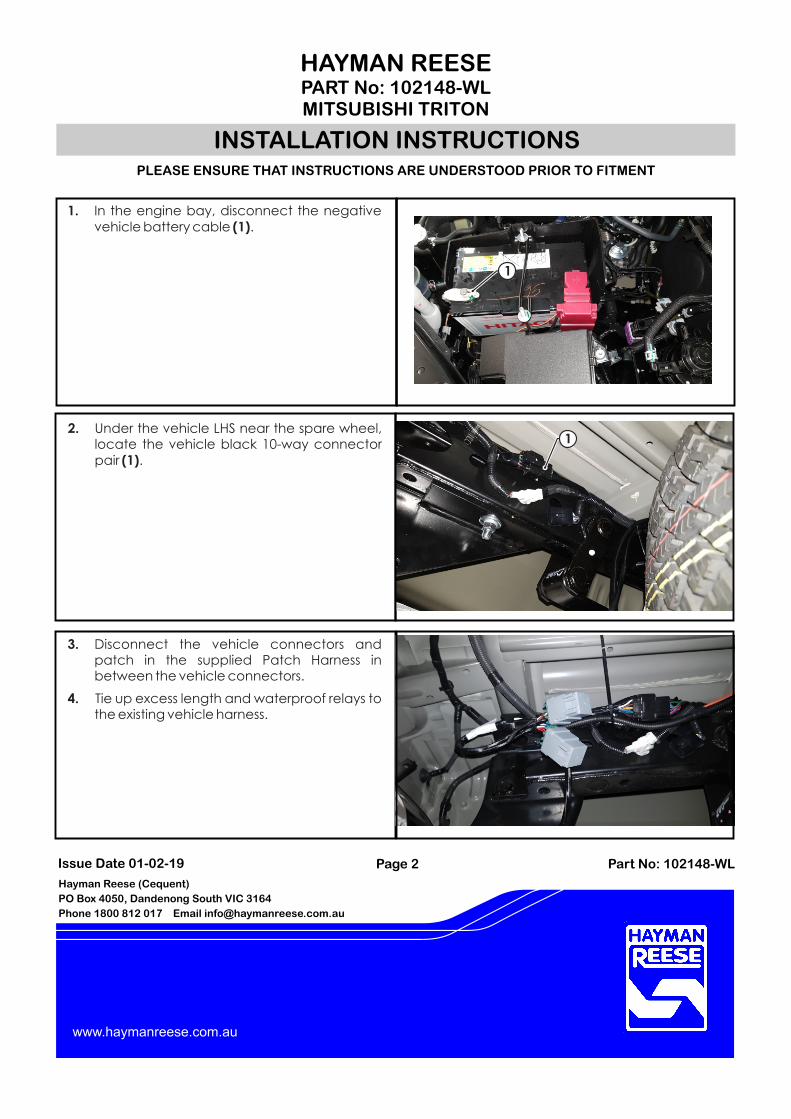
3. Disconnect the vehicle connectors and patch in the supplied Patch Harness in between the vehicle connectors.
4. Tie up excess length and waterproof relays to the existing vehicle harness.
1. In the engine bay, disconnect the negative vehicle battery cable (1).
INSTALLATION INSTRUCTIONS
Hayman Reese (Cequent)
PO Box 4050, Dandenong South VIC 3164
Phone 1800 812 017 Email [email protected]
www.haymanreese.com.au
2. Under the vehicle LHS near the spare wheel, locate the vehicle black 10-way connector pair (1).
1
1
HAYMAN REESEPART No: 102148-WLMITSUBISHI TRITON
PLEASE ENSURE THAT INSTRUCTIONS ARE UNDERSTOOD PRIOR TO FITMENT
Part No: 102148-WLIssue Date 01-02-19
1 1
1
1 1
1 1
1 1
Pointers
1

Page 3
INSTALLATION INSTRUCTIONS
Hayman Reese (Cequent)
PO Box 4050, Dandenong South VIC 3164
Phone 1800 812 017 Email [email protected]
www.haymanreese.com.au
5. Route the power and ground wire under the vehicle towards the front of the vehiclefollowing the left hand chassis rail.
6. Route the power and ground wire up in the engine bay, towards the vehicle battery (1).
Note: Keep harness routing clear of all sharp edges, moving parts and places of extreme heat.
7. Connect the orange power wire ring terminal to the battery (1).
8. Connect the white ground wire to the vehicle earthing point (2).
9. Secure tail harness to towbar
10. Connect the tail harness (tail length 1200mm) 8-way connector (1) to the trailer patch mating 8-way connector (2).
11. Apply silicone grease (3) (not supplied)to waterproof connector.
12. Secure all harnesses using supplied Cable Ties.
13. Test the trailer patch function using a light board or multi-meter.
15. Place the fitting instructions in the glove box after fitment.
1
2
1
1
2
3
HAYMAN REESEPART No: 102148-WLMITSUBISHI TRITON
PLEASE ENSURE THAT INSTRUCTIONS ARE UNDERSTOOD PRIOR TO FITMENT
Part No: 102148-WLIssue Date 01-02-19
1 1
1
1 1
1 1
1 1
Pointers
1

FITTING INSTRUCTIONSSmart Pin (55070BL)
HAYMAN REESEPO BOX 4050, Dandenong South, VIC [email protected] I 1800 812 017haymanreese.com.au
• These �tting instructions are supplied to ensureunderstanding of how the SMART PIN should be �tted andused correctly.
• Once installed, we recommend ALL instructions are kept and placed in the vehicle glove box.
NOTE: Routine maintenance and inspection of the towbar & SMART PIN is required. Regularly inspect for wear and check the tightness of the SMART PIN NUT. Follow instructions below to retighten the nut when necessary.
*Do not tow with your vehicle if the R CLIP or the SMART PINNUT is loose or missing. Replacement parts are available from your Hayman Reese Distributor.
Smart Pin Nut
R-Clip
Smart Pin
Fig 1. Smart Pin assembly
Fig 2. Installation of Trailer Ball Mount
Insert Trailer Ball Mount (TBM) into towbar HITCHBOX, aligning hole in TBM SHANK with hole in HITCHBOX (Fig. 2).
Insert SMART PIN through hole in HITCHBOX and hole in TBM SHANK; ensure the LOCATORS are inserted into the NOTCHES in the HITCHBOX (Fig. 3).
STEP 1
STEP 2
Screw SMART PIN NUT onto SMART PIN; tighten SMART PIN NUT until fingerSTEP 3 tight, ensuring TBM is restrained from movement.
Tighten SMART PIN NUT by turning nut a further 1/8th of a turn in the clockwise direction using a 24mm spanner (Fig 4).
STEP 4
Install SMART PIN R CLIP through the hole on the SMART PIN (Fig. 1). STEP 5
Step 4
Fig 4. Tightening of Smart Pin Nut
Locators
Notches
STEP 3
Fig 3. Smart Pin orientation